


DFEH7030D-100M=P3
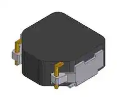
Power Inductor (SMD), AEC-Q200, 10 µH, 3.7 A, Shielded, 4.2 A, DFEH7030D Series
- Manufacturer: MURATA
- Product type: SMD Power Inductors
- SVHC: No SVHC (04-Feb-2026)
| Delivery and price | |
|---|---|
| Units per pack | 1000 |
| Price | 0.815 € |
| Current stock | 1000+ |
| Lead time | 30 days |
1/16

Spec No.J(E)TE243B-9113K-01

## Reference Only

## 参考図  Reference Specifications

## 型名 **Type**

## DFEH7030D

自動車用パワートレイン/セーフティ機器用チップコイル(チップインダクタ) CHIP COIL (CHIP INDUCTOR) for Automotive powertrain/safety equipment

## 外形寸法 **Physical Dimensions**

**==> picture [128 x 75] intentionally omitted <==**

**----- Start of picture text -----**<br>
Inductance code<br>インダクタンス表示<br>Lot No.<br>**----- End of picture text -----**<br>


## **AEC-Q200 Comp.**

**==> picture [289 x 175] intentionally omitted <==**

**----- Start of picture text -----**<br>
L W<br>T<br>E1<br>電極<br>E2 Electrode<br>**----- End of picture text -----**<br>


**==> picture [117 x 94] intentionally omitted <==**

**----- Start of picture text -----**<br>
単位(Unit):mm<br>L 7.0±0.3<br>W 6.6±0.3<br>T 3.0max.<br>E1 1.5±0.3<br>E2 3.2±0.3<br>**----- End of picture text -----**<br>


## インダクタンス表示 **Inductance ID**

- 公称インダクタンス値を 3 文字で表す。The nominal inductance value is identified by 3 digits. 1) 3 桁数字の場合、最初の 2 桁の数字は公称インダクタンス値の有効数 2 桁を表し、 3 桁目の数字は 単位を μH とした場合の 有効数 2 桁に続く 零 の数を表す。 3 digits ID,First 2 digits indicate the effective inductance value The last digit indicates the number of "0"following first 2 digits.The unit is μH.

   - 2) R と 2つの数字で表す場合、単位を μH とし公称インダクタンス値の 小数点の位置をRにて示し、2つの数字と組み合わせて表す。

      - 2 digits and letter "R" ID,The unit is μH. Letter "R"represent the decimal point.

## 優先言語 **Priority language**

優先言語は日本語とする。 Let a priority language be Japanese.

MURATA MFG.CO., LTD.

2/16

Spec No.J(E)TE243B-9113K-01

## Reference Only

## DFEH7030D Type 電気的個別性能 Electrical specifications

|部 品 番 号<br>Customer's Part No.|Part No.<br>品 番|インダクタンス<br>Inductance|インダクタンス<br>Inductance|直流抵抗<br>Resistance<br>DC|直流抵抗<br>Resistance<br>DC|定格電流<br>Rated Current<br>Based on<br>Inductance Change<br>(インダクタンス変化に<br>基づく場合)|定格電流<br>Rated Current<br>Based on<br>Inductance Change<br>(インダクタンス変化に<br>基づく場合)|定格電流<br>(温度上昇に基づく場<br>合)<br>Temperature rise<br>Based on<br>Rated Current|定格電流<br>(温度上昇に基づく場<br>合)<br>Temperature rise<br>Based on<br>Rated Current|
|---|---|---|---|---|---|---|---|---|---|
|||(μH)<br>Nominal<br>Value<br>公称値|(%)<br>許容差<br>Tolerance|||||||
|||||(mΩ) Max.|(mΩ) Typ.|(A)Max.|(A)Typ.|(A)Max.|(A)Typ.|
||DFEH7030D-1R0M=P3|1.0|±20|9.9|8.2|9.0|12.0|9.1|11.0|
||DFEH7030D-1R5M=P3|1.5|±20|15|12|7.3|9.7|7.6|9.5|
||DFEH7030D-2R2M=P3|2.2|±20|18|15|6.9|9.2|7.1|8.9|
||DFEH7030D-3R3M=P3|3.3|±20|29|24|5.3|7.1|5.4|6.7|
||DFEH7030D-4R7M=P3|4.7|±20|41|34|4.2|5.6|4.2|5.3|
||DFEH7030D-5R6M=P3|5.6|±20|54|45|4.1|5.4|3.8|4.7|
||DFEH7030D-6R8M=P3|6.8|±20|59|49|3.9|5.2|3.5|4.4|
||DFEH7030D-8R2M=P3|8.2|±20|78|65|3.2|4.2|3.1|3.9|
||DFEH7030D-100M=P3|10|±20|82|68|3.2|4.2|3.0|3.7|
||DFEH7030D-150M=P3|15|±20|147|122|2.4|3.2|2.2|2.7|
||DFEH7030D-220M=P3|22|±20|198|170|2.0|2.7|1.9|2.4|


*特に指定がない限り、測定は標準状態で行う。

Unless otherwise specified, measurements are the standard  atmospheric condition.

- (1)インダクタンス : LCRメータ 4284A(KEYSIGHT)または同等品により測定。(測定周波数 100kHz 、レベル 0.5V) Inductance : Measured with a LCR meter 4284A(KEYSIGHT) or equivalent.(Test Freq. 100kHz、Level 0.5V)

- (2)直流抵抗 : 抵抗計 3541(HIOKI)または同等品により測定。 DC Resistance 直流抵抗の測定箇所は側面です。

   - : Measured with a Resistance Hitester 3541(HIOKI) or equivalent. The measurement point of DCR is side of terminal.

- (3)定格電流 : 定格電流(インダクタンス変化に基づく場合)又は定格電流(温度上昇に基づく場合)の 何れか小さい方の直流電流値とします。

- Rated Current : Value defined when DC current flows and Rated Current (Based on Inductance change) or when DC current flows and Rated Current (Based on Temperature rise) whichever is smaller.

- ・定格電流 : 定格電流(インダクタンス変化に基づく場合)とはインダクタンスが初期値より20%低下した時の (インダクタンス変化に基づく場合) 電流値。 ・Rated Current : The saturation allowable DC current value is specified when the decrease of the (Based on Inductance change) initial Inductance value at 20%. ・定格電流 : 定格電流(温度上昇に基づく場合)とは、試験基板に実装したインダクタに直流を (温度上昇に基づく場合) 流した時の製品温度上昇が 40℃ に達する電流値。 ・Rated Current : Rated Current (Based on Temperature rise) is specified when temperature of the (Based on Temperature rise) inductor on our PCB for test purpose is raised 40℃ by DC current. (4)絶対最大電圧 : 絶対最大電圧は50V DC です。 Withstand voltage : Withstand voltage 50V DC.

MURATA MFG.CO., LTD.

3/16

Spec No.J(E)TE243B-9113K-01

## Reference Only

|Spec No.J(E)TE243B-9113K-01<br>3/16|Spec No.J(E)TE243B-9113K-01<br>3/16|Spec No.J(E)TE243B-9113K-01<br>3/16|Spec No.J(E)TE243B-9113K-01<br>3/16|
|---|---|---|---|
|DFEH7030D Type一般仕様General  Specifications    ( 1/2 )||||
||項 目Item|規 格Specification|条 件Condition|
|1|使用温度範囲|-40 ~ +155℃|自己温度上昇を含む。(⊿T=40℃ Max.)|
||Operating temperature||Including self temperature rise.(⊿T=40℃Max.)|
||range|||


MURATA MFG.CO., LTD.

4/16

Spec No.J(E)TE243B-9113K-01

## Reference Only

## DFEH7030D Type 一般仕様 General  Specifications    ( 2/2 )

## 標準状態 **Standard atmospheric conditions**

特に指定が無い限り、測定は常温(温度 15~35℃)、常湿(湿度25~85%)にて行う。 ただし、判定に疑義を生じた場合は温度20±2℃、湿度60~70%、気圧86~106kPaにて行う。

Unless otherwise specified, the standard range of atmospheric conditions in making measurements and test as follows; Ambient temperature  :  15℃ to 35℃ , Relative humidity  :  25% to 85% If more strict measurement is required, measurement shall be made within following limits; Ambient temperature  :  20±2℃ , Relative humidity  :  60% to 70% , Air pressure  :  86kPa to 106kPa リフローはんだ条件 **Reflow soldering condition** *リフロー回数 : 2回まで Reflow times : 2 times max *リフロー炉の熱源には、遠赤外線を推奨致します。 熱源としてハロゲンランプを使用されますと、輻射熱が 高く、耐熱範囲を超える場合があり推奨できません。 We recommend infrared ray as heat source of reflow bath.

## ゚ ー 推奨ハ タ ン図 **Recommended PCB pattern**

## ランド寸法設計 **Land pattern designing (Reflow Soldering)**

リフローはんだ付け時の標準ランド寸法を下記に示します。

標準ランド寸法は、電気特性、実装性を考慮して設計されています。この寸法以外で設計されますと、 これらの性能が十分発揮できないことがあります。場合によっては、位置ずれ等のはんだ付け不良と なることがありますので、貴社にてご確認の上ご使用ください。

Recommended land pattern for reflow soldering is as follows:

It has been designed for Electric characteristics and solderability. Please follow the recommended patterns. Otherwise, their performance which includes electrical performance or solderability may be affected, or result to "position shift" in soldering process.

**==> picture [143 x 123] intentionally omitted <==**

**==> picture [65 x 10] intentionally omitted <==**

**----- Start of picture text -----**<br>
単位  Unit  :  mm<br>**----- End of picture text -----**<br>


MURATA MFG.CO., LTD.

5/16

Spec No.J(E)TE243B-9113K-01

## Reference Only

|Spec No.J(E)TE243B-9113K-01<br>5/16|Spec No.J(E)TE243B-9113K-01<br>5/16|Spec No.J(E)TE243B-9113K-01<br>5/16|Spec No.J(E)TE243B-9113K-01<br>5/16|
|---|---|---|---|
|||||
|DFEH7030D Type信頼性試験項目一覧Reliability Test Item List [1/2]||||
||項 目Item|規 格Specification|条 件Condition|
|1|耐熱性<br>High Temperature Exposure <br>AEC-Q200 Test No.3|初期値に対する<br> Lの変化率  ± 10%以内<br>Change from an initial value<br>L<br>:<br>within ± 10%|温度+155℃中に 1000時間放置後、常温常湿中に<br>放置し、24±2時間以内に測定。<br>The specimen shall be stored at a temperature of +155℃<br>for 1000 h.  Then it shall be stabilized under standard<br>atmospheric conditions.<br>Measurement at 24±2 hours after test conclusion.|
|2|温度サイクル<br>Temperature Cycling<br>AEC-Q200 Test No.4|初期値に対する<br>Lの変化率  ± 10%以内<br>Change from an initial value<br>L<br>:<br>within ± 10%|-40℃(30分)→常温(2分以内)→+155℃(30分)→常温<br>(2分以内)を1サイクルとし、これを 1000サイクル行い、<br>常温常湿中に放置し、24±2時間以内に測定。<br>The specimen shall be subjected to 1000 continuous cycles<br>of temperature change of -40℃for 30 min and +155℃for<br>30 min with the transit period of 2min or less. Then it shall be<br>stabilized under standard atmospheric conditions.<br>Measurement at 24±2 hours after test conclusion.|
|3|耐湿性<br>Biased Humidity<br>AEC-Q200 Test No.7|初期値に対する<br>Lの変化率  ± 10%以内<br>Change from an initial value<br>L<br>:<br>within ± 10%|温度+85℃、湿度85%中に 1000時間放置後、<br>常温常湿中に放置し、24±2時間以内に測定。<br>The specimen shall be stored at a temperature of +85℃<br>with relative humidity of 85% for 1000 h.  Then it shall be<br>stabilized under standard atmospheric conditions.<br>Measurement at 24±2 hours after test conclusion.|
|4|高温負荷<br>Operational Life<br>AEC-Q200 Test No.8|初期値に対する<br>Lの変化率  ± 10%以内<br>Change from an initial value<br>L<br>:<br>within ± 10%|温度+115℃中に 1000時間定格電流印加後、<br>常温常湿中に放置し、24±2時間以内に測定。<br>The specimen shall be stored attime-rating current<br>in temperature +115℃after 1000 h. Then it shall be<br>stabilized under standard atmospheric conditions.<br>Measurement at 24±2 hours after test conclusion.|
|5|外形寸法<br>Physical Dimension<br>AEC-Q200 Test No.10|外形寸法仕様による<br> According to specification|デジタルノギスおよび光学顕微鏡を用いて測定<br>Measures using digital slide calipers and an optical microscope.|
|6|耐薬品性試験<br>Resistance to Solvent<br>AEC-Q200 Test No.12|初期値に対する<br>Lの変化率  ± 10%以内<br> Change from an initial value<br>L<br>:<br>within ±10%|イソプロピルアルコール(+25±5℃)中に5分間浸し<br>1時間放置後、測定。<br>Immerse in Isopropyl-Alcohol for 5 minutes at +25±5°C.<br>Measurement at 1 hour after test conclusion.|
|7|耐衝撃性<br>Mechanical shock<br>AEC-Q200 Test No.13|初期値に対する<br>Lの変化率  ± 10%以内<br> Change from an initial value<br>L<br>_:_<br>within ± 10%|加速度Peak acceleration<br>:981 m/s2(≒100G)<br>作用時間Duration of pulse<br>:6 ms<br>6方向に各 3回(計 18回)<br>:3 times in each of 6(±X, ±Y, ±Z) axes.<br>Three successive shock shall be applied in the perpendicular<br>direction of each surface of the specimen.|
|8|耐振性<br>Vibration<br>AEC-Q200 Test No.14|初期値に対する<br>Lの変化率  ± 10%以内<br> Change from an initial value<br>L<br>_:_<br>within ± 10%|掃引割合10~2000~10Hz、掃引時間20分、全振幅1.5mm、<br>5G  X・Y・Z 方向に各 4時間(計 12時間)加える。<br>The specimen shall be subjected to a vibration of 1.5mm<br>amplitude , sweep time 20min , 5G , sweep frequency 10~2000Hz<br>(10Hz to 2000Hz to 10Hz) for 4 h in each of 3(X, Y, Z) axes.|
|||||


MURATA MFG.CO., LTD.

6/16

Spec No.J(E)TE243B-9113K-01

## Reference Only

DFEH7030D Type 信頼性試験項目一覧     Reliability Test Item List [2/2]

**==> picture [509 x 726] intentionally omitted <==**

**----- Start of picture text -----**<br>
|||||||||
|---|---|---|---|---|---|---|---|
|項|目   Item|規|格   Specification|条|件   Condition|
|9|はんだ耐熱性|初期値に対する|試験方法  Test method|
|Resistance to|Lの変化率  ± 10%以内|MIL-STD-202G METHOD 210F Test condition Kに基づく。|
|solder heat|リフローはんだ  Reflow soldering method|
|温度条件|・+183℃以上 above +183℃ ,|90~120 s|
|Temperature condition|・+250±5℃  ,  30±5s|
|AEC-Q200 Test No.15|試料を板厚0.8mmガラスエポキシ基板に置き、上記|
|条件にてリフロー炉を3回通す。|
|Based on MIL-STD-202G METHOD 210F Test condition K.|
|Change from an initial value|The specimen shall be subjected to the reflow process|
|L|:|within ± 10%|under the above condition 3 times.|
|Test board shall be 0.8 mm thick.  Base material shall|
|be glass epoxy resin.|
|測定  Measurement|
|常温常湿中に1時間放置後測定。|
|The specimen shall be stored at standard atmospheric|
|conditions for 1 h in prior to the measurement.|
|10|ESD 試験|初期値に対する|両端子及び本体上部に各3回印加する。|
|ESD|Lの変化率  ± 10%以内|接触放電:1C (1000 V (DC) to < 2000 V (DC))|
|(AEC-Q200-002 Component Classification:1C)|
|AEC-Q200 Test No.17|Change from an initial value|Test conditions:|
|L|:|within ± 10%|3 times in each of terminals and top side of component.|
|Direct contact discharge:1C (1000 V (DC) to < 2000 V (DC))|
|11|はんだ付け性|浸漬した電極面の 90%|電極を常温にてフラックスを塗布し下記条件にて|
|Solderability|以上新しいはんだで覆わ|プリヒート後試料全体をはんだ槽に浸漬する。|
|れている事。|J-STD-002 Condition SMD)C Method D|
|AEC-Q200 Test No.18|New solder shall cover|Electrode shall be immersed in flux at room temperature|
|90% minimum of the surface|and then shall be immersed in solder bath after preheat.|
|immersed.|・はんだ付け Soldering|+245±5℃  ,  5s|
|12|電気的評価|温度-40~+155℃の間で測定。|
|Electrical Characterization|電気的個別性能による|パラメータ試験のロット、サンプル数要求、最大、最小、平均を確認。|
|試験環境温度の最大、最小で実施。|
|AEC-Q200 Test No.19|According to specification|To be measured in the range of -40℃ to +155℃.|
|Parametrically test per lot and sample size requirements,|
|summary to show Min, Max, Mean and Standard deviation|
|at roomas well as Min and Max operating temperatures.|
|13|たわみ強度|初期値に対する|矢印の方向に曲げ幅 2mmになるまで毎秒約 0.5mmの速さで|
|Board Flex|Lの変化率  ± 10%以内|加圧し 60秒間保持する。|
|AEC-Q200 Test No.21|Change from an initial value|Apply pressure gradually in the direction of the arrow at a rate of about|
|L|:|within ± 10%|0.5mm/s until bent depth reaches 2mm and hold for 60 s.|
|Press|i|ng|d|ev|ic|e|
|() U|mea|
|R340|
|基板  Board : 40 × 100mm|
|Si|
|iN|45|a2N|“SpecAi|sm|en /\|厚さ  Thickness  1.6mm|
|14|固着強度|初期値に対する|R0.5の押し治具を使用して、矢印の方向|radius|0,5|mm|
|Terminal Strength|Lの変化率  ± 10%以内|に静荷重を加え60秒間保持する。|DUT|\|
|測定は、荷重を取り去った後に行なう。|
|AEC-Q200 Test No.22|Change from an initial value|A static load using a R0.5 pressing tool shall|Swsubstrate:|a|—),|q1.|widethickness|
|L|:|within ± 10%|be applied to the body of the specimen in the|press tool|nNshear|force|
|direction of the arrow and  shall be hold for 60s.|
|Measure after removing pressure.|荷重 Pressure|18N|

**----- End of picture text -----**<br>


MURATA MFG.CO., LTD.

7/16

Spec No.J(E)TE243B-9113K-01

## Reference Only

## DFEH7030D Type 梱包仕様 Packing  Specifications

## 1. テープ寸法図 **Tape Dimensions**

引き出し方向 Unreeling direction

||||単位Unit  :  mm|
|---|---|---|---|
|A|7.1 ±0.1|P1|12.0 ±0.1|
|B|7.8 ±0.1<br>+0.1|P2|2.0 ±0.05|
|D0|φ1.5<br>- 0<br>+0.1|T1|0.4 ±0.05|
|E|1.75 ±0.1<br>±0.1|T2|3.3 ±0.1<br>±0.3|
|F|7.5 ±0.1|W|16.0 ±0.3<br>-~~0.1~~|
|P0|4.0 ±0.1||<br> ~~0.1~~|


・装着テープ材質   Carrier tape material 単位(Unit):mm ポリスチレン   Polystyrene

・シールテープ材質   Fixing seal tape mater ポリエチレン および ポリエチレンテレフタレート

Polethylene and Polethylene Terephthalate ・シールテープ剥離強度

The force to peel away the fixing seal tape 0.2~0.7N

## 2. テーピング方法 **Taping method**

( トップカバーテープ側からみる。 )

(The direction shall be seen from the top cover tape side. )

上面図(Top view) 引き出し方向

Unreeling direction

## 3. リール寸法図 **Reel dimensions**

||単位Unit  :  mm|
|---|---|
|A|±2<br>φ330|
|B|±0.5<br>17.5|
|C|±1<br>21.5|
|D|±1<br>φ80|
|E|±0.2<br>φ13|
|F<br>G|±0.8<br>±0.3<br>2<br>φ21|
|G|±0.3<br>2|


・リール材質   Reel material

ポリスチレン    Polystyrene

・表示   Marking

貴社部品番号,数量,RoHS comp. Customer's part number, Quantity, RoHS comp.

## 4. 数量 **Quantity**

個/リール 1,000 pieces/reel

## 5. 梱包箱 **Packing box**

・梱包箱材質   Packing box material 紙   Kraft paper

・収納数   Real quantity per packing box 1リール 1reel/1box

・表示   Marking

貴社部品番号,数量,RoHS comp. Customer's part number, Quantity, RoHS comp.

MURATA MFG.CO., LTD.

8/16

Spec No.J(E)TE243B-9113K-01

## Reference Only

## DFEH7030D Type 注意事項 Precautions

## 使用上の注意事項(安全対策) **Notice**

## 1,  樹脂コーティング Resin coating

製品を樹脂で外装される場合、樹脂のキュアストレスが強いとインダクタンスが変化したり製品の性能に 影響を及ぼすことがありますので、樹脂の選択には十分ご注意下さい。また、実装された状態での信頼性評 価を実施下さい。

The inductance value may change and/or it may affect on the product's performance due to high

cure-stress of resin to be used for coating / molding products. So please pay your careful attention whenyou select resin. In prior to use, please make the reliability evaluation with the product mounted in your application set.

- 2, この商品は、従来形のコイルに比べ、絶縁抵抗が低いため、ご使用にあたり注意が必要です。 This product employs a core with low insulation resistance, Pay strict attention when use it.

   - a) コイルの下には電極部を除きスルーホールやパターンの設置をお避け下さい。

   - a) Do not make any through holes and copper pattern under the coil. except a copper pattern to the electrode.

   - b) コイルに他の部品が触れない様にご設計をお願いします。

   - b) Design/mount any components not to contact this product.

## 3, フェールセーフ Fail-safe

- 当製品に万が一異常や不具合が生じた場合でも、二次災害防止のために完成品に適切な フェールセーフ機能を必ず付加して下さい。

Be sure to provide an appropriate fail-safe function on your product to prevent a second damage that may be caused by the abnormal function or the failure of our product.

## 4, 定格上の注意 Caution(Rating)

定格電流を超えてのご使用は避けてください。定格電流を超えて使用しますと、当製品は発熱し、 ワイヤー間のショート、断線あるいははんだが溶けて部品が脱落する恐れがあります。

Do not exceed maximum rated current of the product. Thermal stress may be transmitted to the product and short/open circuit of the product or falling off the product may be occurred.

- 5, 温度上昇 Temperature Rise

   - コイルの温度はご設計環境で大きく変わります。

   - 熱設計には充分ご注意をされ温度保証範囲でのご設計をお願いします。

Temperature rise of power choke coil depends on the installation condition in end products.

It shall be confirmed in the actual end product that temperature rise of power choke coil is in the limit specified temperature class.

## 6, 洗浄について Cleaning

洗浄する場合は支障がないことをご確認の上ご使用ください。

If a washing process is applied,please make sure there is no problem with operating.

- 7,  標準はんだ付け条件 Standard Soldering Conditions 半田方式 リフローでご使用ください。

Please use reflow be soldering method.

## 使用フラックス、はんだ Flux, Solder

## ・ロジン系フラックスをご使用下さい。

## ・Use rosin-based flux.

フラックス ・酸性の強いもの[ハロゲン化物含有量0.2(wt)%(塩素換算値)を超えるもの]は Flux 使用しないで下さい。 ・Don’t use highly acidic flux with halide content exceeding 0.2(wt)% (chlorine conversion value). ・水溶性フラックスは使用しないで下さい。 ・Don’t use water-soluble flux. はんだ ・Sn-3.0Ag-0.5Cu 組成の無鉛はんだをご使用下さい。 Solder ・Use Sn-3.0Ag-0.5Cu solder

MURATA MFG.CO., LTD.

9/16

Spec No.J(E)TE243B-9113K-01

## Reference Only

## DFEH7030D Type 注意事項 Precautions

## 使用上の注意事項(安全対策) **Notice**

## その他 **Other**

## `腐食性ガス` Corrosive gas

腐食性ガス(イオウ系ガス[硫化水素、二酸化イオウなど]、塩素、アンモニア、など)の環境にさらされる、 または前記腐食性ガス環境下にさらされたオイルなど(切削油、シリコーン油等)と接触した場合に、 製品電極の腐食などによって特性劣化または劣化からオープンに至る可能性がありますので、 ご使用はお避けください。なお、当環境下でのご使用について弊社は一切の責任を負いません。

Please refrain from use since contact with environments with corrosive gases

(sulfur gas [hydrogen sulfide, sulfur dioxide, etc.], chlorine, ammonia, etc.) or oils (cutting oil, silicone oil, etc.)

that have come into contact with the previously stated corrosive gas environment will result in deterioration of product quality or an open from deterioration due to corrosion of product electrode, etc.

We will not bear any responsibility for use under these environments.

MURATA MFG.CO., LTD.

10/16

Spec No.J(E)TE243B-9113K-01

## Reference Only

## DFEH7030D  Type 注意事項 Precautions

## 実装上の取り扱い注意 **Notice**

## 8,  使用上の注意 Notice

本製品は、はんだ付けにて接合されることを意図して設計しておりますので、導電接着剤での接合等の方法を使用 される場合は事前に弊社にご相談ください。

This product is designed for solder mounting.

Please consult us in advance for applying other mounting method such as conductive adhesive.

## 8-1,  部品配置 Product's location

## 基板設計時、部品配置について次の点にご配慮下さい。

   - ① 基板のそり・たわみに対して、ストレスが加わらないように部品を配置して下さい。

- The following shall be considered when designing and laying out P.C.B.’s.

① P.C.B. shall be designed so that products are not subject to the mechanical stress due to warping the board.

## [部品方向 Products direction]

**==> picture [172 x 59] intentionally omitted <==**

**----- Start of picture text -----**<br>
a<br>b<br>〈 Poor example 〉 〈 Good example 〉<br>**----- End of picture text -----**<br>


ストレスの作用する方向に対して、 横向き(長さ:a<b)に部品を配置して 下さい。

Products shall be located in the sideways direction to the mechanical stress.

MURATA MFG.CO., LTD.

11/16

Spec No.J(E)TE243B-9113K-01

## Reference Only

## DFEH7030D  Type 注意事項 Precautions

## 実装上の取り扱い注意 **Notice**

②基板ブレイク付近での部品配置  Components location on P.C.B. separation. 基板分割でのストレスを軽減するために下記に示す対応策を実施することが有効です。 下記に示す3つの対策をすべて実施することがベストですが、ストレスを軽減するために可能な限りの 対策を実施ください。

It is effective to implement the following measures, to reduce stress in separating the board.

It is best to implement all of the following three measures; however, implement as many measures as possible to reduce stress.

## 対策内容 Contents of Measures ストレスの大小 Stress Level A > D *1 ration surface.ation surface.tion surface.on surface.n surface.surface.rface.ace.. A > B

- `(1)基板分割面に対する部品の配置方向を平行方向とする。`

- Turn the mounting direction of the component parallel to A > D *1 the board separation surface.ation surface.tion surface.on surface.n surface.surface.rface.ace..

- (2)基板分割部にスリットを入れる。

- Add slits in the board separation part.

- (3)基板分割面から部品の実装位置を離す。

   - Keep the mounting position of the component away from A > C the board separation surface.

      - *1 上記の関係は、手割はカットラインに対して垂直に応力が

      - Perforation `C` かかることが前提です。 `B` ディスクカット機などの場合は、応力が斜めにかかり、 A > D の関係が成り立ちません。

      - `D` *1    A > D is valid when stress is added vertically to

      - `A` the perforation as with Hand Separation. Slit If a Cutting Disc is used, stress will be diagonal to the PCB, therefore A > D is invalid.

## ③ネジ穴近辺での部品配置

ネジ穴近辺に部品を配置すると、ネジ締め時に発生する 基板たわみの影響を受ける可能性があります。 ネジ穴から極力離れた位置に配置してください。

③ Mounting Components Near Screw Holes

Recommended When a component is mounted near a screw hole, Screw Hole it may be affected by the board deflection that occurs during the tightening of the screw. Mount the component in a position as far away from the screw holes as possible.

- 8-2,  基板、周辺部品の耐熱温度 Temperature rating of the circuit board and components located around 当製品に定格電流(温度上昇に基づく場合)を通電すると、製品温度が最大40℃上昇しますので、基板および周辺 `部品の耐熱温度にはご注意下さい。`

Temperature may rise up to max. 40 `℃` when applying the rated current to the Products.

Be careful of the temperature rating of the circuit board and components located around.

- 8-3,  製品の取り扱い Caution for use 磁気の影響でインダクタンスが変わる可能性があります。 取り扱いの際には、磁気を帯びたピンセットや磁石などは使用しないで下さい。 (樹脂や陶器で先端加工されたピンセットなどをご使用下さい。)

   - There is possibility that the inductance value change due to magnetism.

Don‘t use a magnet or a pair of tweezers with magnetism when chip coil are handled.

(The tip of the tweezers should be molded with resin or pottery.)

MURATA MFG.CO., LTD.

12/16

Spec No.J(E)TE243B-9113K-01

## Reference Only

## DFEH7030D  Type 注意事項 Precautions

## 実装上の取り扱い注意 **Notice**

## 8-4,  基板の取扱い   Handling of a substrate

部品を基板に実装した後は、基板ブレイクやコネクタの抜き差し、ネジの締め付け等の際、基板のたわみや ひねり等により、部品にストレスを与えないようにしてください。

- 過度な機械的ストレスにより部品にクラックが発生する場合があります。

After mounting products on a substrate, do not apply any stress to the product caused by bending or twisting to the substrate when cropping the substrate, inserting and removing a connector from the substrate or tightening screw to the substrate.

Excessive mechanical stress may cause cracking in the product.

## **Bending**

## **Twisting**

## その他 **Other**

## 磁気飽和  Magnetic Saturation

## 定格電流を超えた電流が流れた場合、磁気飽和によりインダクタンス値が低下します。

When the excessive current over rated current is applied, the inductance value may change due to magnetism.

MURATA MFG.CO., LTD.

13/16

Spec No.J(E)TE243B-9113K-01

## Reference Only

## DFEH7030D Type 注意事項 Precautions

## 使用上の注意事項(安全対策) **Notice**

## 9, 保管・運搬 Storage and Handling Requirements

- ① 保管期間

- 納入後、6ヶ月以内にご使用下さい。

- なお、6ヶ月を超える場合は、はんだ付け性をご確認の上ご使用ください。

- ② 保管方法

- ・当製品は、温度-10℃~+40℃、相対湿度15%~85%で、且つ、急激な温湿度の変化の ない室内で保管ください。

硫黄・塩素ガス・酸など腐食性ガス雰囲気中で保管されますと、電極が酸化し、はんだ付け性不良が 生じたり、製品の巻線部分が腐食する等の原因となります。

- ・バルクの状態での保管は避けてください。バルクでの保管は製品同士あるいは製品と他の部品が 衝突し、コアカケや断線を生じることがあります。

- ・湿気、塵などの影響を避けるため、床への直置は避けパレットなどの上に保管ください。

- ・直射日光、熱、振動などが加わる場所での保管は避けてください。

- ③ 運搬

過度の振動、衝撃は製品の信頼性を低下させる原因となりますので、取り扱いには充分注意をお願い します。

## (1) Storage period

Use the products within 6 months after delivered.

Solderability should be checked if this period is exceeded.

## (2) Storage conditions

- Products should be stored in the warehouse on the following conditions.

Temperature : -10 ~ 40°C

Humidity : 15 to 85% relative humidity No rapid change on temperature and humidity

Don't keep products in corrosive gases such as sulfur,

chlorine gas or acid, or it may cause oxidization of electrode, resulting in poor solderability.

- Products should not be stored on bulk packaging condition to prevent the chipping of the core and the breaking of winding wire caused by the collision between the products.

- Products should be stored on the palette for the prevention of the influence from humidity, dust and so on.

- Products should be stored in the warehouse without heat shock, vibration, direct sunlight and so on.

## (3) Handling Condition

Care should be taken when transporting or handling product to avoid excessive vibration or mechanical shock.

MURATA MFG.CO., LTD.

14/16

Spec No.J(E)TE243B-9113K-01

## Reference Only

## DFEH7030D Type 注意事項 Precautions

## 使用上の注意事項(安全対策) **Notice**

- 10, ディレーティング  Derating

   - 各周囲温度環境下においてはディレーティングカーブの負荷以下にて使用して下さい。

Max. current (DC, AC) as function of ambient temperature (derating curve)

- IOP :  Loaded Current

- IR :  Rated Current

**==> picture [435 x 269] intentionally omitted <==**

**----- Start of picture text -----**<br>
Current Derating Curve<br>1.2<br>1.0<br>0.8<br>0.6<br>0.4<br>0.2<br>0.0<br>-40 -20 0 20 40 60 80 100 120 140 160<br>Ambient Temperature [ ℃ ]<br>R<br>/I<br>IOP<br>**----- End of picture text -----**<br>


MURATA MFG.CO., LTD.

Spec No.J(E)TE243B-9113K-01

15/16

## Reference Only

## DFEH7030D Type お願い Note

## 適用範囲 **Scope**

当参考図は、DFEH7030Dシリーズに適用します。

This reference specification applies to DFEH7030D series.

## 適用用途 **Specific applications**

・自動車用パワートレイン/セーフティ機器:走る・曲がる・止まるという動作や安全装置等にかかわる自動車用機器、また は、その構造・装置・性能が安全確保もしくは環境保全上の技術基準を満たすよう法律上要求されている機器に使用でき る製品

・自動車用インフォテインメント/コンフォート機器:カーナビ・カーオーディオといった特に人命に直接的にかかわらない自動 車用機器で、かつ、その構造・装置・性能が安全確保もしくは環境保全上の技術基準を満たすよう特に法律上要求されて いない機器に使用できる製品

・医療機器(GHTF Class C)*インプラント、手術、自動投与用途を除く:国際分類クラスGHTF Class Cの医療機器で、かつ、 その不具合が人体へのリスクが比較的高いと考えられる機器に使用できる製品

・医療機器(GHTF Class A及びB) :国際分類クラスGHTFでClass A及びClass Bで規定される医療機器で、かつ、その機能 が人命及び財産の保護に直接的にかかわらない機器に使用できる製品

•Automotive powertrain/safety equipment: Products that can be used for automotive equipment related to running, turning, stopping, safety devices, etc., or equipment whose structure, equipment, and performance are legally required to meet technical standards for safety assurance or environmental protection.

•Automotive infotainment/comfort equipment: Products that can be used for automotive equipment such as car navigation systems and car audio systems that do not directly relate to human life and whose structure, equipment, and performance are not specifically required by law to meet technical standards for safety assurance or environmental protection.

•Medical equipment (GHTF Class C) *Except for Implant/surgery/auto injector: Products that can be used for medical equipment of Class C of the international classification class GHTF and whose malfunction is considered to pose a relatively high risk to the human body.

•Medical equipment (GHTF Class A and B): Products that can be used for medical equipment regulated by Class A and Class B of the international classification class GHTF and whose functions do not directly relate to the protection of human life and property.

## 適用外用途 **Unsuitable application**

## 当参考図の「用途の限定」に書かれている用途

Applications listed in “Limitation of applications” in this reference specification.

MURATA MFG.CO., LTD.

Spec No.J(E)TE243B-9113K-01

16/16

## Reference Only

DFEH7030D Type `お願い` Note ~~pe~~ A 注意 **Caution**

用途の限定 Limitation of Applications 当参考図に記載の製品は、当参考図内で個別に記載の適用用途向けに設計・製造されたものであり、 高度な性能・機能・品質・管理・安全性が要求される本注意書き末尾①から⑪までの用途への適合性・性能発揮・ 品質等を保証するものではありませんので、当参考図記載の適用用途に従ってご使用ください。 万が一、当参考図記載の適用用途以外の用途でご使用された場合、

又は以下の①から⑪までの用途でご使用された場合(別途当参考図内に用途記載があるものは除く*)には、 弊社は当該使用によって生じた不測の事故その他の損害に関する一切の責任を負いかねますのでご注意ください。 ①航空機器 ②宇宙機器 ③海底機器 ④発電所制御機器 ⑤医療機器 ⑥輸送機器 ⑦交通用信号機器 ⑧防災/防犯機器⑨産業用情報処理機器⑩燃焼/爆発制御機器⑪その他上記機器と同等の機器 当参考図に記載の適用用途以外の用途に対応した製品については、お客様とお取引のある弊社営業窓口・ 代理店・商社、またはお問い合わせフォーム(https://www.murata.com/contactform)までお問い合わせください。

*製品によっては、①から⑪までの用途向けに設計・製造される場合があり、それらは当参考図に個別で用途を記載してお ります。

The products listed in the reference specification (hereinafter the product(s) is called as the “Product(s)”) are designed and manufactured for applications specified in the reference specification (hereinafter called as the “Specific Application”). We shall not warrant anything in connection with the Products including fitness, performance, adequateness, safety, or quality, in the case of applications listed in from (1) to (11) written at the end of this precautions, which may generally require high performance, function, quality, management of production or safety. Therefore, the Product shall be applied in compliance with the specific application.

WE DISCLAIM ANY LOSS AND DAMAGES ARISING FROM OR IN CONNECTION WITH THE PRODUCTS INCLUDING BUT NOT LIMITED TO THE CASE SUCH LOSS AND DAMAGES CAUSED BY THE UNEXPECTED ACCIDENT, IN EVENT THAT (i) THE PRODUCT IS APPLIED FOR THE PURPOSE WHICH IS NOT SPECIFIED AS THE SPECIFIC APPLICATION FOR THE PRODUCT, AND/OR (ii) THE PRODUCT IS APPLIED FOR ANY FOLLOWING APPLICATION PURPOSES FROM (1) TO (11) (EXCEPT THAT SUCH APPLICATION PURPOSE IS UNAMBIGUOUSLY SPECIFIED AS SPECIFIC APPLICATION FOR THE PRODUCT IN OUR CATALOG SPECIFICATION FORMS, DATASHEETS, OR OTHER DOCUMENTS OFFICIALLY ISSUED BY US*).

(1) Aircraft equipment  (2) Aerospace equipment (3) Undersea equipment (4) Power plant control equipment

(5) Medical equipment (6) Transportation equipment (7) Traffic control equipment (8) Disaster prevention/security equipment

(9) Industrial data-processing equipment (10) Combustion/explosion control equipment

(11) Equipment with complexity and/or required reliability equivalent to the applications listed in the above.

For exploring information of the Products which will be compatible with the particular purpose other than those specified in the reference specification, please contact our sales offices, distribution agents, or trading companies with which you make a deal, or via our web contact form.

Contact form: https://www.murata.com/contactform

* We may design and manufacture particular Products for applications listed in (1) to (11). Provided that, in such case we shall unambiguously specify such Specific Application in the reference specification without any exception. Therefore, any other documents and/or performances, whether exist or non-exist, shall not be deemed as the evidence to imply that we accept the applications listed in (1) to (11).

## お願い Note

- 1, ご使用に際しては、貴社製品に実装された状態で必ず評価して下さい。

- Please make sure that your product has been evaluated in view of your specifications with our product being mounted to your product.

- 2, 当製品を当参考図の記載内容を逸脱して使用しないで下さい。

You are requested not to use our product deviating from the reference specifications.

- 3, 当参考図の内容は予告なく変更することがございます。ご注文の前に、納入仕様書の内容をご確認いただくか 承認図の取り交わしをお願いします。

- The contents of this reference specification are subject  to change without advance notice.

   - Please approve our product specifications or transact the approval sheet for product specifications before ordering.

MURATA MFG.CO., LTD.
Updated at April 25, 2026
Established in Kyoto in 1944, Murata has grown into a global leader in the design and manufacture of advanced electronic components, specializing in ceramic passive components, wireless connectivity modules, and power conversion technologies. Renowned for its foundational work in materials science and process innovation, Murata delivers solutions that drive the evolution of modern electronics across telecommunications, mobility, industrial, and healthcare applications. This extensive portfolio is anchored by a broad selection of high-performance passive components, heavily focused on inductive solutions. Engineers can choose from hundreds of specialized RF inductors and power inductors engineered for exceptional reliability, efficiency, and miniaturization. The range also features robust EMC and RFI suppression solutions, highlighted by industry-leading common mode chokes and power line filters designed to ensure signal integrity and strict regulatory compliance in demanding circuit environments. Beyond inductive and filtering components, the offering encompasses a comprehensive array of critical circuit protection, timing, and power devices. Murata's precision NTC and PTC thermistors provide essential temperature sensing and thermal management, while its robust lineup of ceramic resonators and quartz crystals ensures highly accurate frequency control. Supported by premium non-rechargeable batteries, polymer capacitors, and advanced sensing transducers, Murata equips designers with the versatile building blocks required for next-generation technological development.
About Novapart
Novapart is a B2B electronic component broker specialising in stock shortages and cost reduction. We source hard-to-find parts and identify compliant alternatives across a catalogue of 410,000+ components from 500+ manufacturers.
Learn more →Stock Shortage Specialist
When a component is unavailable, discontinued or has an unacceptable lead time, we tap into our network of vetted European and Asian distributors to source what you need — without compromising on quality or traceability.
Request a quote →Compliant Alternatives
We identify pin-to-pin, electrically equivalent substitutes that meet the same certifications (RoHS, AEC-Q100, REACH) as your original specification — validated against datasheets, not just part numbers. Often at a lower cost.
BOM Analysis service →