
Image not available
Illustrative purposes only

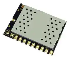
DELTA-TRX8C1
Alarm Systems Module, FM, 500Kbps, 868MHz, -121dBm, 1.8V to 3.6V Supply, SPI, UART
⚠️ Reference pricing provided. In case of supply shortages, we will connect you with our trusted procurement partners to ensure your project's continuity.
- Manufacturer: RF SOLUTIONS
- Product type: RF Transceivers - Sub 2.4GHz ISM Band
- Data Rate Max: 500Kbps
- Frequency Max: 868MHz
- RF Modulation: FM
- Transmit Power: 20dBm
- Sensitivity dBm: -121dBm
- Module Interface: SPI, UART
- Supply Voltage Max: 3.6V
- Supply Voltage Min: 1.8V
- RF Transceiver Applications: Alarm Systems, Fire and Security, Home Automation, Sensors and Networks, Telemetry
| Delivery and price | |
|---|---|
| Units per pack | 100 |
| Price | 16.68 € |
| Current stock | 10+ |
| Lead time | 30 days |
Datasheet

-

-

-

-

-

-

-

-

-

-

-

-

-

-

-

   -

   -

   -

   -

-

-

Note: The two programming pins “JP1” and ANT GND are not shown in diagram as these 12 are not required 5 or 11 GND GND 1 )O Vcc 2 SPIO MOSI 3 k ~~O~~ egq SPIO MISO 4 ~~TO~~ SPIO SCLK 5 im ~~——~~ im SPI NSS 6 **J** QL>O} 4. oOU [] U f : b ~~—~~ Oo NIRQ / UART TX 7 g ~~an~~ = Oo SPIO ENABLE/ 8 UART RX Md J ~~o~~ GND 9 10 GND

**==> picture [467 x 106] intentionally omitted <==**

**----- Start of picture text -----**<br>
Vcc<br>SAW  Band  LNA FIFO<br>Filter pass<br>GND<br>Band  filter<br>pass filter<br>RX<br>ANT Band  PA nSEL<br>CONTROL IC |<br>RF  pass  || SDI<br>TX switch filter |_| SDO<br>Band  SCLK<br>pass filter XTAL | nIRQ<br>**----- End of picture text -----**<br>


? ® y x oS Oo‘autmS

DELTA Class1 Capable RF Transceiver.

## Generic Application Schematic —using UART to a PIC16F886

**==> picture [507 x 580] intentionally omitted <==**

**----- Start of picture text -----**<br>
43.3V -<br>=<br>+3,3¥ =<br>ty<br>: VWPP/REZ16F886-SOIC28RB7/PRGDAT = ()<br>5 RAG RBS!PRGCLE 36<br>44 RALa2 RBSres} 352 || ,-———_}#* |<br>z | RAS RBS 35 =: GND GND Ce<br>7 RAA RB2 a =o ine =<br>a RAS RB1 oT C2 eo SPIO_MOSI <<br>5 | VSS REO SPIO MISO<br>in RAY VDO is AI SPIO_ SCLE<br>li RAG WSs rw SPIO NSS<br>RCO PUCT/ RX Pe) UART_TxX<br>= Roi RC6/Txees EExzee — =2 UART_RX-<br>ia Ros RCS is SND Mi Uo<br>DELTA_RFOOTPRINT_TH<br>Ici<br> Application Schematic — — using SPI to a PIC16F886<br>+3.3V<br>L<br>+3,.3V 5<br>w<br>3] VPP/RES16F836-SOIC28 RB7/PRGDAT [$s (]<br>5 Rad RBG) PRIGICLK e .<br>4 RAL RES 35 C1<br>5 RAZ Re4 7a<br>eae rot | o—<———_- —... |<br>7 RA4 RBZ a GND - GND G4<br>= RAS RBI 22 Dee wee =<br>3 VSS Re0 += —— /—4ps?10_most =<br>40 ag wop 22 cD BIO MISO EDISPIO_MISOtb<br>il | pag wss 2 i [Ser spi0_scik<br>22 Roo ROCF s/RK 18 =~ SPIO_NSS<br>Jaca receTx LAE FGI UART_TX /'SPIO_NIRQ<br>RCZ rces/spo -1® a: UART_RX /SPIO_ENABLE ho<br>RC3/SCK  RC4/SDI FOGND iy =<br>ST<br>= Note pin 8 on M1 goes to GND to enable SPI mode<br>**----- End of picture text -----**<br>


## Generic Application Schematic — — using SPI to a PIC16F886

www.rfsolutions.co.uk

## DELTA Class 1 Capable RF Transceiver

**==> picture [52 x 51] intentionally omitted <==**

**----- Start of picture text -----**<br>
axe®<br>N<br>**----- End of picture text -----**<br>


## SPI Command Set and Interface

## Mode Select

|Command for ATM Mode|Command for ATM Mode|Command for ATM Mode|
|---|---|---|
||||
|1|RX|When RXmode selected will default to last setting set usingATR<br>command or if not set.|
|3|Ready|Ready is a low powerwake state which can be used for fast entry<br>to RX or switching between TXand RX. Time to RX orTX from<br>READY <1ms|
|||Low power sleep mode with register retention.|


Example: Put the module into receiver mode

|Command|A|T|M|1|
|---|---|---|---|---|
|Decimalbytevalue|65|84|77|1|


## Receiver Mode

|Command for Receiver Mode: ATR CHANNEL, PACKET LENGTH|Command for Receiver Mode: ATR CHANNEL, PACKET LENGTH|Command for Receiver Mode: ATR CHANNEL, PACKET LENGTH|
|---|---|---|
||||
||Packet length|The length of the data packet to follow|


Example: Enter RECEIVE mode and wait for a 10 byte packet

Command A T R 10 Decimal byte value 65 84 82 10

## Transmit Mode

|Command for Transmit Mode: ATS CHANNEL, PACKET LENGTH, DATA|Command for Transmit Mode: ATS CHANNEL, PACKET LENGTH, DATA|Command for Transmit Mode: ATS CHANNEL, PACKET LENGTH, DATA|
|---|---|---|
||||
|~~Fata~~|Packet length<br>~~Fata~~|The length of the data packet to follow. In 8 bit bytes.<br>~~Yourdatatobetransmitted.(Data=DataPacket*PacketLength)~~|
|~~Fata~~|~~Fata~~|~~Yourdatatobetransmitted.(Data=DataPacket*PacketLength)~~|


Example: Send a 10 byte data packet

Command A T S 10 DATA PACKET 0-255 Decimal byte value 65 84 83 10 0-255

www.rfsolutions.co.uk

**==> picture [543 x 52] intentionally omitted <==**

**----- Start of picture text -----**<br>
DELTA Class . eo<br>aS1 Capable RF Transceiver  eo)axeSSN<br>**----- End of picture text -----**<br>


## SPI Command Set and Interface continued

## Module RF Sync Bytes:

**==> picture [358 x 56] intentionally omitted <==**

**----- Start of picture text -----**<br>
Command for Sync Byte: ATA SYNC1, SYNC2, SYNC3, SYNC4<br>SYNCK Po Reverse Order Bits I.e. 2D = B4 and D4 = 2B<br>**----- End of picture text -----**<br>


Example: send SYNC BYTES to 12, 34, 56, 78 Command A T A 12 34 56 78 Decimal byte value 65 84 65 12 34 56 78

## Set RF TX Power

Command for ATP TX POWER TX PWR 0-127 in 0.25db steps, where +20dbm is 127

Example: Sets the RF TX power to 19

Command A T P 19 Decimal byte value 65 84 80 19

## DATA Packet Received

IRQ GOES LOW

READ FIRST TWO BYTES FROM MODULE SHOULD BE #R

FOLLOWED BY THE PACKET LENGTH, RSS! VALUE AND DATA PACKET

NOTE: In order to be suitable for Class certification the DELTA modules Baud rates are fixed to the following values:

RF Baud Rate : 9600bps (GFSK)

Host Baud Rate: 19,200bps

www.rfsolutions.co.uk

DELTA a Class 1 Capable RF Transceiver

eo SN 0‘auta,

x

## Ping-Pong (Walk test)

The DELTA has a built in walk test mode that allows users to performance test via simple commands. By setting both transmitter and receiver into this mode, the transmitter will broadcast a packet to the receiver (ping) and the receiver will output #RZYXWVUTSRO (this is simply #R and then 10 letters of the alphabet in reverse) to show that the ping command has been received. The receiver will then send a packet back to the transmitter (pong). The transmitter will output #T followed by the RSSI value (Received Signal Strength Indication). If no reply packet is received back from the receiver with 200ms the RSSI value will be O.

The below command will place DELTA into ping-pong mode as a transmitter. The transmitter will output every 200ms the RSSI value of a valid packet through its UART RX pin.

## AI T#000

## Channel number (byte value)

The screen shot below shows a terminal window and the received data on the RX pin. The image shows the data packet that is output when a successful ping-pong takes place on the transmitter.

|& Terminalv1.9b - 201112308 - byBr@y++<br>Disconnect| { COM Patt<br>Baudrate<br>—<br>-<br>Data bits) Patty —)<br>ea<br>**|** [oeI Coo © samc tis200|/ 2 |cam <br>bow.|__coMs| vera eadseh v7<br>San <br>Quit<br>© 9600<br>56000 © custom ||© 8<br>© space|& Terminalv1.9b - 201112308 - byBr@y++<br>Disconnect| { COM Patt<br>Baudrate<br>—<br>-<br>Data bits) Patty —)<br>ea<br>**|** [oeI Coo © samc tis200|/ 2 |cam <br>bow.|__coMs| vera eadseh v7<br>San <br>Quit<br>© 9600<br>56000 © custom ||© 8<br>© space|-<br>Stop bits) -Handshaking<br> |S<br>||eaters<br> a<br>Perearcemnenre<br>|© 2<br>©RTS<br>onTx [7 invert|-<br>Stop bits) -Handshaking<br> |S<br>||eaters<br> a<br>Perearcemnenre<br>|© 2<br>©RTS<br>onTx [7 invert|a|x|
|---|---|---|---|---|---|
|=<br>ResetCounter| [OS] Counter= 171<br>HEN FF Dee TF Bin|Staittog||Request/Response|||
|ao<br>Send File fj IT CR=CR+LF<br>BREAK,||||Gor=|=|
|ee|<br>|<br>|<br>|<br>|<br>|<br>||||||<br>|<br>||||
||||||||
|Zonnected<br>Rx 987<br>Tx 4<br>RxOK||||||
|The screen shot below shows the values output by the transmitter during the walk testwhen no packet is received||||||
|back from the receiver.||||||
|About. |)_COMs||! ~ agog 3e400 ¢ 256000|| 7 |]@ mark<br>‘Quit<br>© 9600<br>© 56000<br>© custom || © 8<br>© space||||© 2|**©** **RTS**/CTS+XON/XOFF<br>onTX [<br>invert|||
|Receive||||||
|CLEAR| ResetCounter| [0 3] Counter= 2<br>Ces fe hee | Ot|Stathog||Request/Response|||
|a<br>SendFile<br>fo 3] > CR=CR+LF<br>BREAK||||Gore|Gyars|
|S| S| S| S|S| | SS)|| SS)||SS) SS) S||||
|fn|||||Ren|
|ee||||||
|Connected<br>Ax. 188<br>Tx 4<br>Rx OK||||||
||||wvww.rfsolutions.co.uk|||


DELTA a Class 1 Capable RF Transceiver

**==> picture [94 x 50] intentionally omitted <==**

**----- Start of picture text -----**<br>
e<br>X oS<br>0‘auta,<br>**----- End of picture text -----**<br>


To configure the DELTA into receiver mode for the ping-pong walk test, the following string needs to be sent to the TX pin.

**==> picture [95 x 12] intentionally omitted <==**

**----- Start of picture text -----**<br>
ATR#000#010<br>**----- End of picture text -----**<br>


Channel number (byte value) 10 byte payload (this is the only byte value that will enter the device into ping -pong)

**==> picture [536 x 333] intentionally omitted <==**

**----- Start of picture text -----**<br>
The screen shot below shows a terminal window with a successful packet received, here you can see the HEX val-<br>ues for #RZYXWVUTSRQ (This being the TEN BYTES and the #R showing receiver).<br>About COMs Clason Flssa0 escnon 90 wae ae CIRTSCTSRON OFF<br>Quit © 9600 ¢ 56000 © custom || © 8 © space) © 2 © RTS on TX [~ invert<br>_ ResetCounter| OS] Couner= 16 |HEX, Bee F 8m statog Request/Response<br>P|<br>et Send File Pp a  CR=CR+LF BREAK Corre Garr<br>= ee ee ee | ee | | |<br>F a rr woootO1O R Send<br>**----- End of picture text -----**<br>


www.rfsolutions.co.uk

## DELTA Cl Class Capabl ‘4 aS1 Capable RF Transceiver eo)aXN

## Electrical Parameters

## Absolute Maximums

## Recommended Operating Conditions

|~~fanbetenpeswre ~~|~~of ~~|~~of ~~|~~of ~~|~~of ~~||~~|~~|~~|~~|~~|~~|||~~ts | ~~|~~ts | ~~|~~ts | ~~|~~ts | ~~|~~|~~|~~|~~|||
|---|---|---|---|---|---|---|---|---|---|---|---|---|---|---|---|---|---|---|
||||||||||||||||||||
|DC Characteristics|||||||||||||||||||
||||||||||||||||||||
|Current|||||||||||||||||||
|Ready|||||||||||||||||||
|Sleep<br>~~fRemodecuret~~<br>~~|~~<br>~~|~~<br>~~[xmedecurens~~<br>~~|~~<br>SynthesizerAC Electrical Characteristics||||||||~~Cd~~|||||~~|~~||||||
||||||||||||||||||||
|Range|||||||||||||||||||
|Synthesizer frequency|||||F pes-s68|||850-870|||||14.4|||||Hz|
|Resolution|||||||||||||||||||


## Auxiliary Block Specifications

|ter<br>~~seemed~~|||||||
|---|---|---|---|---|---|---|
||||||||
||~~seemed~~|~~seemed~~|~~seemed~~|~~seemed~~|~~seemed~~|~~seemed~~|


www.rfsolutions.co.uk

axe® NY

## DELTA Class 1 Capable RF Transceiver

## Receiver AC electrical characteristics

|~~RXfrequencyrange~~<br>~~|~~|~~|Fn~~|~~P85~~|~~P85~~|~~P85~~<br>~~870~~|~~P85~~<br>~~870|~~|~~P85~~<br>~~|MHZ|~~|
|---|---|---|---|---|---|---|
|~~RXfrequencyrange~~<br>~~|~~|~~|Fn~~|~~P85~~|~~P85~~|~~P85~~<br>~~870~~|~~P85~~<br>~~870|~~|~~P85~~<br>~~|MHZ|~~|
|~~RXfrequencyrange~~<br>~~|~~|~~| Fn ~~|~~P85~~<br>(2.4 kbps, GFSK, BT = 0.5,<br>DF = +30 kHz, 114 KHz Rx BW)|~~P85~~|~~P85~~<br>~~870~~|~~P85~~<br>~~870 |~~|~~P85~~<br>~~| MHZ |~~|
||Pro|(BER < 0.1%)<br>(40 kbps, GFSK, BT = 0.5,<br>DF = #25 kHz, 114 kHz Rx BW)||-108||dBm|
|||(128 kbps, GFSK, BT = 0.5,<br>DF = 70 kHz, 305 kHz Rx BW)|||||
||Pax. oox|(BER < 0.1%,1 Kbps, 185 kHz Rx BW, OOK,<br>PN15 data)||-113||dBm|
|||(BER< 0.1%,40 kbps,185 kHz RxBW, OOK,<br>PN15 data)||-102||dBm|
||||||||
|BERvariation vs power<br>Level2<br>~~RSSIresolution~~<br>~~PRES~~<br>~~+1-Ch~~|Prax res<br>~~PRES PO~~|Up to +5 dBm Input Level<br>~~PO~~|~~PO~~<br>~~05~~|~~PO~~<br>~~05~~|0.1<br>~~PO~~|ppm<br>~~PO~~|
|~~RSSIresolution~~<br>~~PRES~~<br>~~+1-Choffsetselectivity~~|~~PRES PO~~|~~PO~~<br>DesiredRefSignal3dBabovesensitivity,~~|~~|~~PO~~<br>~~05~~<br>~~|—|~~|~~PO~~<br>~~05~~<br>~~|-se|~~|~~PO~~<br>~~|—|~~|~~PO~~<br>~~|dB|~~|
|~~RSSI resolution~~<br>~~PRES~~<br>~~+1-Ch~~ ~~offsetselectivity~~|~~PRES PO~~|~~PO~~<br>Desired Ref Signal 3 dB above sensitivity, ~~|~~<br>BER < 0.1%. Interferer is CWand desired<br>modulated with 1.2 Kbps,<br>DF = 5.2 kHz, GFSK with BT= 0.5,<br>RX BW=58 kHz channel spac-<br>ing = 100 kHz<br>Desiredrefsignal3dBabovesensitiv-ity,~~|~~|~~PO~~<br>~~05~~<br>~~|—|~~|~~PO~~<br>~~05~~<br>~~|-se|~~|~~PO~~<br>~~|—|~~|~~PO~~<br>~~|dB|~~|
|~~offset selectivity~~<br>+2-Ch offset selectivity<br>~~Blocking200kHz-1MHz~~|C/locx||~~| — |~~<br>~~|—|~~|~~| -se |~~<br>_59<br>~~|8[|~~|~~| — |~~<br>~~[|—|~~|~~| dB |~~<br>~~|ab|~~|
|~~Blocking200kHz-1MHz~~<br>Blocking~~1Mizoffset~~|7M|Desired ref signal 3 dB above sensitiv- ity, ~~|~~<br>BER < 0.1%. Interferer isCWand desired<br>modviatedwith12kbos<br>DF = 5.2 KHz GFSK with BT = 0.5,<br>motes|~~|—|~~<br>~~|__~~|~~|8[|~~<br>61<br>~~|__~~<br>~~“et~~|~~[|—|~~<br>~~|__~~~~**|**~~<br>~~=~~|~~|ab|~~<br>~~**|**~~<br>~~8~~|
|~~Blocking 200 kHz-1 MHz~~<br>Blocking~~1Mizoffset~~|7M||~~| — |~~<br>~~|__~~|~~| 8 [|~~<br>61<br>~~|__~~<br>~~“et~~|~~[| — |~~<br>~~|__~~~~**|**~~<br>~~=~~|~~| ab |~~<br>~~**|**~~<br>~~8~~|
|~~1Miz offset~~<br>;<br>~~nga~~|8M||~~|__~~<br>~~Te~~|~~|__~~<br>~~“et ~~<br>-79<br>~~Te~~|~~|__~~~~**|**~~<br> ~~=~~<br>~~Te~~|~~**|**~~<br>~~8~~<br>~~Te~~|
||<br>‘ect<br>mage rejection|Mees|Rejection atthe imagefrequency<br>IF = 468 kHz||-35|||
|Spurious emissions|Pos-rxi|Measured at RX pins||-54||dBm|


www.rfsolutions.co.uk

axe® NY

## DELTA Class 1 Capable RF Transceiver

## Transmitter AC electrical characteristics

||Symbol||||||
|---|---|---|---|---|---|---|
|~~a~~|~~a~~||||||
|~~DOKdalerats~~|~~a~~|~~ee~~|~~eee~~|~~eee~~|||
|~~DOKdalerats~~|~~a~~|~~ee~~|~~eee~~|~~eee~~|||
|~~DOK dale rats~~|~~a~~|~~ee ~~|~~eee~~|~~eee~~|||
|resolution|||||||
||1X||||||
|TXRFoutputsteps||Usingswitchedcurrentmatch within<br>6 dB ofmax power||01|||
|TX RF output level||5|||||
|TXRFoutput level<br>Variationvs. frequency|pp<br>RF_FREQ|Measured across850-870MHz||0.5|||
|Transmit modulation<br>filtering|BT|Gaussian filteringbandwidth time<br>product||0s|||
|Spurious emissions|Posi|Pour = +13 dBm,<br>Frequencies<1 GHz<br>~~1-12.75GHz,excludingharmonics~~<br>~~|~~|~~|—|~~|o4<br>~~|-42|~~|~~|—|~~|dBm<br>~~|dBm|~~|
|||~~1-12.75GHz,excludingharmonics~~<br>~~|~~|~~|—|~~|~~|-42|~~|~~|—|~~|~~|dBm|~~|
|Harmonics|P2urem|~~1-12.75 GHz, excluding harmonics~~<br>~~|~~<br>Using reference designTX matching<br>network and filter with max output<br>power. Harmonics reduce linearlywith<br>output power.|~~| — |~~|~~| -42 |~~<br>-42|~~| — |~~|~~| dBm |~~<br>dBm|
||P3yisen|||-42||dBm|


www.rfsolutions.co.uk

**==> picture [155 x 118] intentionally omitted <==**

**----- Start of picture text -----**<br>
22.0<br>2.63<br>pre)<br>Ke)<br>Ke) 2.97<br>)O| 0.84<br>1.77<br>2.54<br>28.9<br>**----- End of picture text -----**<br>


**==> picture [115 x 90] intentionally omitted <==**

**----- Start of picture text -----**<br>
2.45 9.96 18.37<br>LJ<br>PCB pad Layout<br>1.77<br>2.54<br>**----- End of picture text -----**<br>


®

DELTA Class1 Capable RF Transceiver.

**==> picture [95 x 49] intentionally omitted <==**

**----- Start of picture text -----**<br>
sd<br>XS on<br>0‘auta,<br>**----- End of picture text -----**<br>


## Range Test1 In a Built up area within buildings—2KM

The range test was carried out in HOVE, East Sussex in clear atmospheric conditions.

The DELTA modules were mounted on Small prototyping boards with a simple piece of wire as antenna (not ideall)

One DELTA module was placed on the roof of a vehicle and connected to a laptop (via LVTTL RS232) and a packet was sent every 0.5 seconds via a terminal program. The second DELTA module was connected to a laptop anda terminal window was used to view the packet (ASCII characters)

**==> picture [513 x 361] intentionally omitted <==**

**----- Start of picture text -----**<br>
J<br>aa f . a Mee et<br>< Mano t 4 - Portslade ==<br>Southwick g g T Hall Rd Shelldale Rd . ] Portland re<br>5 s Southwick % Portslade Cemetery ‘A Vale Rd 8 J<br>Albert S S Recreation Yay Fiehereqatese nerd vale R & 3 2<br> p 2 4 Ground cardner Rd cladsto® é g 2 g 2 §<br>Croft AV FISHERSGATE) = Sg 2 2 8<br>N & n g 82066 a & =<br>& Southwicki2= The Gardens "3 [epee 3 = StAng, ia<br>Butts Rd<br>a ii habe! Ra = q 5 ons 2 New ch<br>st & Wemoto Albion st A259 A259 2 2 Be es g<br>®iver Adur A259 2 : 3 > 2 < = @ od<br>Basin RdS C2 GS & é = & 5<br>" its Cafe Bar Kingsway © @&<br>Basin Rds ay<br>2km Basin rgg —Sn has ModelHoveYacht LagoonClub ~a g,<br>**----- End of picture text -----**<br>


www.rfsolutions.co.uk

**9km**
Updated at February 9, 2023
About Novapart
Novapart is a B2B electronic component broker specialising in stock shortages and cost reduction. We source hard-to-find parts and identify compliant alternatives across a catalogue of 420,000+ components from 500+ manufacturers.
Learn more →Stock Shortage Specialist
When a component is unavailable, discontinued or has an unacceptable lead time, we tap into our network of vetted European and Asian distributors to source what you need — without compromising on quality or traceability.
Request a quote →Compliant Alternatives
We identify pin-to-pin, electrically equivalent substitutes that meet the same certifications (RoHS, AEC-Q100, REACH) as your original specification — validated against datasheets, not just part numbers. Often at a lower cost.
BOM Analysis service →