
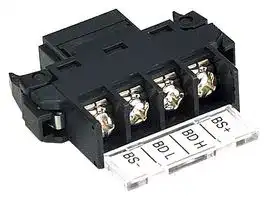


DCN4-TB4.
TERMINAL BLOCK, ADAPTER, SCREW CONNECT
- Manufacturer: OMRON INDUSTRIAL AUTOMATION
- Product type: Controller Accessories
- Current Rating:-; Product Range:- 40M8881
- Product Range: -
- Current Rating: -
| Delivery and price | |
|---|---|
| Units per pack | 1 |
| Price | 30.26 € |
| Current stock | 10+ |
| Lead time | 30 days |
# **M u l t i - v e n d o r  N e t w o r k**

## ~~**Support for Machine Automation Controller NJ-Series!**~~

## ~~**Support for open network**~~

~~**The MX2 series/ MX2 series V1 type/ RX series V1 type* can be connected to DeviceNet by mounting the Communications Unit.**~~

- Supported for the MX2 series Ver.1.1 or higher. ~~Not Supported for the RX series without V1 type.~~

## ~~**8 types of remote I/O higher functions**~~

~~**8 types of remote I/O functions that exchange I/O data automatically without program are provided.**~~

~~**All of the following functions of the inverter can also be used.**~~

- ~~Simple positioning control~~

- Torque control

- ~~Setting of acceleration/deceleration time etc.~~

## ~~**Parameter Edit via DeviceNet**~~

~~**Parameters of the inverter can be edited via DeviceNet communication**~~ ***** ~~**by using CX-Drive , support tool of inverter/servo drive. No tool switching required.**~~

- ~~Supported for CX-Drive Ver.2.6 or higher.~~

**==> picture [241 x 72] intentionally omitted <==**

**----- Start of picture text -----**<br>
MX2 series V1 type  RX series V1 type<br>DeviceNet  DeviceNet<br>Communication Unit Communication Unit<br>3G3AX-MX2-DRT-E 3G3AX-RX-DRT-E<br>P. 109 P. 110<br>**----- End of picture text -----**<br>


**F-2**

i

## **Selecting a Network Is a Strategic Decision. to Evolve.**

## **Intelligent Slaves (PLC Units)**

|INDEX|INDEX|**Intelligent Slaves (PLC Units)**<br>,|
|---|---|---|
|**Overview**<br>**Introducing DeviceNet Products**<br>**Network Specifications**<br>**Master Units**<br>**CJ-series DeviceNet Unit (CJ1W-DRM21)**<br>**CS-series DeviceNet Unit (CS1W-DRM21-V1)**<br>**F-4**<br>**F-12**<br>**F-19**<br>**1**<br>**2**<br>**3**<br>~~me~~||**Programmable Slaves (CPM2C-S1**@**OC-DRT)**<br>**Intelligent Slaves**<br>**Digital Sensor Communications Unit**<br>**(E3X-DRT21-S VER.3 )**<br>**DeviceNet ID Slave (V600-HAM42-DRT)**<br>**DeviceNet ID Slave (V680-HAM42-DRT)**<br>**1**<br>**88**<br>**92**<br>**94**<br>**95**<br>~~—_~~<br>°<br>~~OO~~|
|**Programmable Controller NSJ Series**<br>**(NSJ**@**-**T@@1**(B)-G5D)**<br>**DeviceNet Board (PCI Board) (3G8F7-DRM21)**<br>**Smart Slaves DRT2 Series**<br>**DRT2-series Smart Slaves**<br>**4**<br>**7**<br>**9**<br>~~me~~||**DeviceNet-compliant Digital Indicator (K3HB-**@**-DRT)**<br>**DeviceNet -compliant Digital Controllers (E5AR-DRT/E5ER-DRT)**<br>**DeviceNet Communications Unit for Modular Temperature Controllers (EJ1-DRT)**<br>**Multi-function Compact Inverter MX2-Series V1 type DeviceNet Communication Unit**<br>**3G3AX-MX2-DRT-E**<br>**High-function General-purpose Inverter RX-Series V1 type DeviceNet Communication Unit**<br>**9**<br>**96**<br>**100**<br>**104**<br>**107**<br>~~-~~|
|7|**Smart Slaves DRT2 Series**<br>**Transistor Remote I/O Terminals**<br>**(DRT2-**@**D08(-1)/**@**D16(-1))**<br>**Expansion Units**<br> **(XWT-ID08(-1)/OD08(-1)/ID16(-1)/OD16(-1))**<br>**Remote I/O Terminal with Relay Outputs (DRT2-ROS16)**<br>**Transistor Remote I/O Terminals with 3-tier**<br>**Terminal Blocks (DRT2-**@**D16TA(-1))**<br>**e-CON Connector Terminals (DRT2-**@**D16S(-1))**<br>**MIL Connector Terminals (with Transistor)**<br>**(DRT2-**@**D32ML(-1)/**@**D16ML(-1))**<br>**Board Terminals with MIL Connector**<br>**(DRT2-**@**D32B(-1)/**@**D32BV(-1))**<br>**Screw-less Clamp Terminals with Transistors**<br>**(DRT2-**@**D16SL(H)(-1)/**@**D32SLH(H)(-1))**<br>**Environment-resistive Terminals with Transistors (High-function Type)**<br>**(DRT2-**@**D08C(-1)/**@**D16C(-1))**<br>**Environment-resistive Terminals with Transistors (Standard type)**<br>**(DRT2-**@**D04CL(-1)/**@**D08CL(-1)/**@**D16CL(-1))**<br>**Analog I/O Terminals (DRT2-AD04(H)/DA02)**<br>**Temperature Input Terminals (DRT2-TS04**@**)**<br>**SmartSlice GRT1 Series**<br>**SmartSlice GRT1 Series**<br>**DeviceNet Communications Unit (GRT1-DRT)**<br>**3G3AX-RX-DRT-E**<br>**CIP Safety on DeviceNet System**<br>**Safety Network Controller NE0A-SCPU01**<br>**Safety Network Controller NE1A-SCPU Series**<br>**Safety I/O Terminal DST1 Series**<br>**Network Configurator WS02-CFSC1-E**<br>**Configurator and Software**<br>**DeviceNet Configurator Ver.2.**@**WS02-CFDC1-E**<br>**DeviceNet Configurator PC Card (Software Included)**<br>**3G8E2-DRM21-V1**<br>**DeviceNet Analyzer WS02-ALDC1**<br>**NX-Server WS02-NX**@**C1**<br>**Device Inspector WS02-DIPC1**<br>**Peripheral Devices**<br>**General-purpose Peripheral Devices**<br>**Peripheral Devices for Environment-resistive Slaves**<br>**Ordering Information**<br>**Ordering Information**<br>**Information**<br>**Related Manuals**<br>**Introduction of the Switch Mode Power Supply**<br>**10**<br>**18**<br>**22**<br>**26**<br>**28**<br>**31**<br>**34**<br>**39**<br>**43**<br>**48**<br>**51**<br>**57**<br>**60**<br>**64**<br>**68**<br>**108**<br>**111**<br>**112**<br>**117**<br>**122**<br>**125**<br>**127**<br>**128**<br>**128**<br>**130**<br>**131**<br>**132**<br>**133**<br>**134**<br>**144**<br>**159**<br>**160**<br>**175**<br>**176**<br>**177**<br>~~eseee~~<br>~~Ba ee~~<br>~~me~~<br>~~ON~~||
||**SmartSlice I/O Units**<br>**70**||
||**MULTIPLE I/O TERMINAL Series**<br>**MULTIPLE I/O TERMINAL Series**<br>**Communications Unit (DRT1-COM)**<br>**72**<br>**73**||
||**Digital I/O Units**||
||**(GT1-**@**D16(-1)/**@**D16MX(-1)/**@**D16ML(-1)/**<br>@**D32ML(-1)/**@**D16DS(-1))**<br>**Relay Output Units (GT1-ROS16/ROP08/FOP08)**<br>**Analog I/O Units (GT1-AD/DA)**<br>**74**<br>**81**<br>**83**||
||**Temperature Input Unit (GT1-TS04**@**)**<br>**85**||


Windows is registered trademarks of Microsoft Corporation in the USA and other countries. DeviceNet[TM] , EtherNet/IP[TM] , CompoNet[TM] and CIP Safety[TM] are the trademarks of ODVA. Other company names and product names in this document are the trademarks or registered trademarks of their respective companies.

**F-3**

**on a Global Scale. What Is DeviceNet? DeviceNet is a field network that easily performs mutual connections between control devices, such as PLCs, computers, and sensors, as well as data devices, such as barcode readers and RFID Systems. DeviceNet is a standardized network that enables intelligent control of field devices and improves system productivity.** Information level Controller level **Ethernet/IP** Device level **DeviceNet** Sensor & Actuator level **CompoNet Easy and flexible wiring and layout High-speed Noise response resistance** . > 3e ane **DeviceNet Features Global Standardization standard Enhanced Simple safety maintenance** Sp- **F-4**

## **Used Worldwide. and IT Technology at Manufacturing Sites**

DeviceNet covers a wide array of FA applications, ranging from the sensor or device level to the controller level. With its superior installation performance, DeviceNet easily achieves mutual connections between sensors and other control devices in one network as well as reducing costs and shortening lead time in many aspects of manufacturing, ranging from design and manufacture of equipment and lines to installation, operation, and maintenance.

**==> picture [349 x 136] intentionally omitted <==**

**----- Start of picture text -----**<br>
24-VDC power supply for network<br>Terminating Multidrop = Terminating<br>resistance Tap Tap Tap resistance<br>Device Tap<br>=<br>Tap Tap<br>Device<br>» Device<br>Device Device Device<br>T-branch<br>Device<br>a , Device Device ae = Device Device<br>Device<br>Branching to<br>Star connections<br>branch lines<br>(Branch line length: 6 m max.)<br>**----- End of picture text -----**<br>


DeviceNet has been the leader in standardization required for this age of borderless manufacturing as a standard for a variety of countries and industrial organizations, such as with standard sensor bus certification by the SEMI industrial association and compliance with IEC, an international global standard. Equipment and lines at manufacturing sites overseas can be constructed and operated in the same way as at sites in Japan without the need for training on wiring rules or detailed explanations.

**IEC SEMI** E54.4-0997 62026-3 **CENELEC** EN50325-2 **ISO** 11898 GB T18858.2-2002

Support is provided for creating maintenance systems that provide failure prediction as preventive maintenance to reduce equipment downtime, which is a constant issue at manufacturing sites. => **Page F-6** Using DeviceNet lets you create safety control networks and program logic. Monitoring with safety controls makes maintenance easier. **Page F-8** =>

**F-5**

## regicont >

**DRT2-series Smart Slaves are Intelligent                 Slaves with Powerful Support for Your Networks from Installation                          to Maintenance**

**OMRON DRT2-series Smart Slaves decrease total costs and reduce work when used in a variety of manufacturing site applications, such as maintenance and quality control. The Slave Units monitor the network's power supply voltage and communications errors, which can be easily read using Support Software. In addition, the number of ON/OFF operations and total operating time of the devices wired to the slave are counted at the slave, which enables providing notification when maintenance is required.**

**==> picture [535 x 130] intentionally omitted <==**

**----- Start of picture text -----**<br>
Control System Maintenance System<br>DeviceNet<br>Configurator<br>Operation time monitor<br>Preventive maintenance  Contact operation counter<br>of equipment<br>Unit ON time monitor<br>Slave and connected component comments<br>Ethernet Reduced startup time I/O power status monitor<br>Reliable equipment  Network power voltage<br>startup monitor<br>PLC ai Reduced downtime Communications error history<br>Introducing<br>DeviceNet Products<br>Network<br>Specifications<br>**----- End of picture text -----**<br>


**Machine Operation Monitored by Slaves Easy-to-view Display**

## **Slaves with Powerful Support to Maintenance**

## Device Net -

**==> picture [504 x 340] intentionally omitted <==**

**----- Start of picture text -----**<br>
Control System  Maintenance System<br>I DeviceNet<br>II Configurator  Operation time monitor<br>I<br>I Preventive maintenance   Contact operation counter<br>I of equipment<br>3 Unit ON time monitor<br>Zi Slave and connected component comments<br>Ethernet  I Reduced startup time  I/O power status monitor<br>Reliable equipment   Network power voltage<br>startup  monitor<br>PLC  Reduced downtime  Communications error history<br>J L_jj||]|] | | Maintenance information  monitor<br>LeBEBlin gg :| Unit ON time   It's time for   What is the<br>monitor   motor   Network power present<br>Control   (See note.)  maintenance!  voltage monitor  communications<br>information  voltage?<br>Ci = = = DeviceNet 2. P 1<br>|<br>DRT2-series<br>Smart Slave<br>The wiring to the  The cylinder's   It might be time   Is the I/O   What was the<br>I/O device is<br>speed is   for a switch   power supply   cause<br>short-circuited<br>incorrect!  inspection!  turned ON?  of the error?<br>or broken!<br>External load   Operation time   Contact operation   I/O power status   Communications error<br>short-circuit detection  monitor  counter (See note.)  monitor  history monitor<br>Note:  The contact operation counter function and the unit ON time monitor function cannot be used simultaneously.<br>**----- End of picture text -----**<br>


## **Using OMRON Temperature Input Terminals for Maintenance**

**==> picture [513 x 288] intentionally omitted <==**

**----- Start of picture text -----**<br>
The operating time of a preset temperature range is counted in 1-s units.<br>and Maintenance<br>I Slaves can notify the  | eho J) l<br>Master when a setting is<br>If prolonging the  exceeded.  Indicator service<br>time it takes to  life control<br>reach a certain<br>Operating time<br>temperature may<br>degrade  ] Gacoossoax Ce i _ |<br>equipment:<br>Input<br>Semiconductor<br>Time<br>manufacturing equipment  I<br>I The peaks or valleys of temperature inputs that change in a regular pattern<br>are counted to predict when devices operating with severe temperature  l<br>I<br>swings are due for maintenance.<br>Short Startup<br>Slaves internally convert  Scaling points for 0% and 100% are set from the  l<br>a display values to  tt Configurator  3<br>temperature input<br>If it takes too long to<br>values so the Controller<br>modify the ladder<br>program on the  program no longer has  Scaling performed   <= 1<br>Master when a  to be modified to  inside the Slave  Sensor replaced by one<br>Temperature Sensor  perform this task.  with a different input range<br>is replaced:<br>Mn _- —_—_ !<br>Temperature<br>**----- End of picture text -----**<br>


**F-7**

## **Complies with the Highest Safety Standards in the World**

**The CIP Safety on DeviceNet System conforms to IEC 61508 SIL3 for functional safety, and EN 954-1 Safety Category 4 for machine safety, complying with the world's highest level of safety standards.**

IEC 61508 SIL 3

EN 954-1 Safety Category 4

Safety circuits must be able to function EN standards evaluate the level of machine risk and require the to provide safety at anytime. Conversely, incorporation of risk minimization measures. In EN 954-1, five safety the degree of lack of safety is used as categories have been established, with Safety Category 4 indicating the indicator. In IEC 61508, safety is designs that require the highest safety design level. This category is

**==> picture [213 x 180] intentionally omitted <==**

**----- Start of picture text -----**<br>
eviceNet &<br>Overview<br>Introducing<br>DeviceNet Products<br>Network<br>Specifications<br>**----- End of picture text -----**<br>


## **Selection for Your Worksite.**

**DeviceNet is a global open multi-vendor network that is spreading worldwide. A wide variety of DeviceNet devices are provided by many vendors. Having recognized the superior flexibility of DeviceNet for FA and its role as a global standard, OMRON provides a broad lineup of compatible devices.**

**In the future, OMRON will continue to enhance solutions using DeviceNet while further developing information technology and open networks.**

**==> picture [105 x 25] intentionally omitted <==**

**----- Start of picture text -----**<br>
CX-Integrator<br>●  Setting and Monitoring at Startup<br>●  Setting in Monitoring at Maintenance<br>**----- End of picture text -----**<br>


**==> picture [213 x 144] intentionally omitted <==**

**----- Start of picture text -----**<br>
Device Inspector<br>WS02-DIPC1 *1<br>NX-Server<br>DeviceNet WS02-NX @ C1 *1<br>Analyzer<br>WS02-ALDC1 *1<br>VME Master Board      Programmable Controllers<br>NSJ Series<br>**----- End of picture text -----**<br>


~~**Programmable Controllers**~~ **CS/CJ Series DeviceNet Unit** ~~CS1W-DRM21-V1~~ CJ1W-DRM21

## ~~**DeviceNet**~~

**Transistor Remote I/O Terminals MIL Connector Terminals Environment-resistive Terminals with Transistor with Transistors** ~~**(High-function Type)**~~

**==> picture [75 x 104] intentionally omitted <==**

**----- Start of picture text -----**<br>
Remote I/O Terminals<br>with 3-tier Terminal<br>Blocks<br>IN<br>Remote I/O Terminals<br>with Relay Outputs<br>**----- End of picture text -----**<br>


**Environment-resistive Terminals with Transistors** ~~**(Standard Type)**~~

**e-CON Connector Terminals** ~~**(Standard Type)** otets eo Wns _ A~~ **Screw-less Clamp** ~~**Terminals**~~ **Analog I/O Terminals** . 4 **Board Terminals** ~~**with MIL connectors Temperature Input Terminals**~~

*1. Final order entry date: The end of March, 2020

**F-10**

## **Know-how Refined at FA Sites, Devices to Enable the Ideal**

## Device| Net T™ i

**==> picture [488 x 216] intentionally omitted <==**

**----- Start of picture text -----**<br>
Multi-function Compact Inverter<br>MX2-Series V1 type<br>DeviceNet Communication Unit<br>3G3AX-MX2-DRT-E<br>Multiple I/O Terminal DeviceNet ID Slaves<br>V680-HAM42-DRT<br>Sa Ss - Safety Network  a<br>Controllers<br>High-function<br>General-purpose Inverter  NE0A-SCPU @ DeviceNet ID Slaves<br>SmartSlice RX-Series V1 type  V600-HAM42-DRT<br>GRT1 Series DeviceNet Communication Unit<br>3G3AX-RX-DRT-E<br>Safety Network<br>Controllers Digital Sensor<br>NE1A-SCPU @ Communications Unit<br>E3X-DRT21-S VER.3<br>**----- End of picture text -----**<br>


~~**DeviceNet**~~ **Communications Unit for Modular Temperature** ~~**Controllers**~~ EJ1-DRT **Digital Panel Meters** K3HB-DRT **Safety I/O Terminals** DST1 Series ~~**DeviceNet-compliant**~~ **Programmable Slaves Digital  Controllers** CPM2C-S100C-DRT E5AR-DRT ~~CPM2C-S110C-DRT E5ER-DRT~~ ~~**CompoBus/S**~~

**F-11**

## **Product Lineup**

## **Masters** ~~SSS~~

**==> picture [479 x 276] intentionally omitted <==**

**----- Start of picture text -----**<br>
■  DeviceNet Unit for  ■  DeviceNet Unit for  ■  Programmable Controllers<br>CJ Series CS Series NSJ Series<br>P. 2 P. 3 P. 4<br>ap ap ep<br>J 8 | | ~~<br>CJ1W-DRM21 CS1W-DRM21-V1 NSJ @ - T@@1 (B)-G5D<br>■  VME Master Board<br>ea» P. 7<br>3G8F7-DRM21<br>**----- End of picture text -----**<br>


**F-12**

## **Slaves**

**==> picture [471 x 645] intentionally omitted <==**

**----- Start of picture text -----**<br>
DRT2 Smart Slaves<br>■  Transistor Remote I/O Terminal   ■  Remote I/O Terminals with  ■  Remote I/O Terminals with<br>3-tier Terminal Blocks Relay Outputs<br>P. 18 P. 28 P. 26<br>tT) ep te )<br>- Ear Aa> - ~ :<br>DRT2-ID16/OD16(-1)  DRT2-ID16TA(-1)  DRT2-ROS16<br>DRT2-MD16(-1)  DRT2-OD16TA(-1)<br>DRT2-ID08/OD08(-1)  DRT2-MD16TA(-1)<br>I/O Expansion Unit<br>XWT-ID16/OD16(-1)<br>XWT-ID08/OD08(-1)<br>■  MIL Connector Terminals  ■  e-CON connector Terminals  ■  Screw-less Clamp Terminals<br>with Transistor  P. 31 with Transistor<br>ea» .<br>P. 34 P. 43<br>ae<br>a -<br>DRT2-ID16S(-1)<br>DRT2-ID32ML(-1)<br>DRT2-MD16S(-1)<br>DRT2-OD32ML(-1)<br>DRT2-MD32ML(-1)<br>DRT2-ID16ML(-1)<br>DRT2-ID16MLX(-1)<br>DRT2-OD16ML(-1)<br>DRT2-OD16MLX(-1)<br>DRT2-ID32SLH(-1)<br>■  Board Terminals with MIL  ■  Temperature Input Terminals  DRT2-OD32SLH(-1)<br>connectors  P. 60 DRT2-MD32SLH(-1)<br>ea» P. 39 DRT2-ID16SL(-1)<br>DRT2-ID16SLH(-1)<br>DRT2-OD16SL(-1)<br>DRT2-OD16SLH(-1)<br>DRT2-ID32B(-1)<br>DRT2-OD32B(-1)<br>DRT2-MD32B(-1)  DRT2-TS04T<br>ay DRT2-ID32BV(-1)  . “ DRT2-TS04P<br>DRT2-OD32BV(-1)<br>DRT2-MD32BV(-1)<br>■  Analog I/O Terminals  ■  Environment-resistive  ■  Environment-resistive Terminals<br>ea» P. 57 Terminals with Transistors  with Transistors (Standard Type)<br>(High-function Type)  ep P. 51<br>ep P. 48<br>a<br>r -<br>DRT2-AD04  ,<br>DRT2-ID04CL(-1)  DRT2-MD16CL(-1)<br>DRT2-AD04H  DRT2-ID08C(-1)<br>DRT2-DA02  DRT2-OD04CL(-1)  DRT2-HD16CL(-1)<br>DRT2-OD08C(-1)<br>DRT2-ID08CL(-1)  DRT2-WD16CL(-1)<br>DRT2-HD16C(-1)<br>DRT2-OD08CL(-1)<br>**----- End of picture text -----**<br>


**F-13**

## **Product Lineup**

## **Slaves**

**==> picture [492 x 519] intentionally omitted <==**

**----- Start of picture text -----**<br>
GRT1 Smart Slaves<br>Se<br>■  DeviceNet Communications Unit ■  SmartSlice I/O Units<br>GRT1-ID4(-1)<br>P. 68 P. 70<br>GRT1-OD4(-1)<br>GRT1-ID8(-1)<br>GRT1-OD8(-1)<br>GRT1-ROS2<br>ef ae BT f f i yl <= GRT1-AD2<br>GRT1-DA2C<br>GRT1-DA2V<br>GRT1-TS2P<br>GRT1-TS2PK<br>GRT1-DRT GRT1-CT1<br>MULTIPLE I/O TERMINAL Series<br>See<br>■  Communications Unit ■  Digital I/O Units ■  Relay Output Units<br>P. 73 P. 74 P. 81<br>ep ae 3 =»<br>GT1-ID32ML(-1)<br>GT1-OD32ML(-1)<br>GT1-ROP08<br>GT1-ID16(-1) GT1-FOP08<br>GT1-OD16(-1)<br>DRT1-COM<br>GT1-ID16ML(-1)<br>GT1-ID16DS(-1)<br>GT1-ID16MX(-1) GT1-OD16ML(-1)<br>GT1-ROS16<br>GT1-OD16MX(-1) GT1-OD16DS(-1)<br>■  Analog I/O Units ■  Temperature Input Units<br>a= P. 83 GT1-AD08MX ee P. 85<br>(connector) GT1-TS04T<br>GT1-DA04MX<br>(connector)<br>a GT1-AD04 aed GT1-DA04 y “4<br>(terminal  (terminal<br>block)  block)<br>GT1-TS04P<br>SD PLC Intelligent Slaves<br>■  Programmable Slaves<br>ae» P. 88<br>**----- End of picture text -----**<br>


**CPM2C-S100C-DRT CPM2C-S110C-DRT**

**F-14**

i

**==> picture [501 x 467] intentionally omitted <==**

**----- Start of picture text -----**<br>
Slaves<br>Intelligent Slaves<br>■ a>  Digital Sensor  ■  DeviceNet  ■  DeviceNet<br>Communications Unit ID Slave ID Slave<br>_ P. 92 = P. 94 ro) P. 95<br>2<br>E3X-DRT21-S VER.3 V600-HAM42-DRT V680-HAM42-DRT<br>■  DeviceNet-compliant  ■  DeviceNet Communications Unit for  ■  DeviceNet-compliant<br>Digital Indicator Modular Temperature Controllers  Digital Controllers<br>_ P. 96 _ P. 104 Tr) P. 100<br>K3HB- @ -DRT EJ1-DRT E5AR-DRT E5ER-DRT<br>■  Multi-function Compact Inverter  ■  High-function General-purpose<br>MX2-Series V1 type  Inverter RX-Series V1 type<br>DeviceNet Communication Unit DeviceNet Communication Unit<br>P. 107 P. 108<br>A<br>3G3AX-MX2-DRT-E 3G3AX-RX-DRT-E<br>**----- End of picture text -----**<br>


**F-15**

## **Product Lineup**

## **Configurators and Software**

## **Configurators**

**==> picture [492 x 305] intentionally omitted <==**

**----- Start of picture text -----**<br>
■  DeviceNet Configurator  Ver.2.@ ■  PC Card DeviceNet Configurator (with software)<br>P. 128<br>[OCR 28/24 we eS trex Mm Ko aa eeeee ar eH<br>P. 128<br>i" o#epb wD e&<br>onfigur:ia Renanae nen rons<br>@ og RoR @<br>vd aoMice) . sposoosBlock [1-[/0]  out [Reisy] =) Sc 3G8E2-DRM21-V1 *1 yj<br>SEO ©<br>WS02-CFDC1-E<br>Analysis Software Monitor Software Diagnostic Tools<br>■  DeviceNet Analyzer ■  NX-Server ■  Device Inspector<br>P. 130 P. 131 P. 132<br>SeZeknw 22122es ar iimwe GEStEEGufmenite cwttsose™4 |] ie2 ie Tposliees——aar wtees;  oreeana ayecafe fv Fe ew e e<br>EE xBeta= en lee peewee getnopeFE SSE i Tine Toe ORE TOR aie BAO Ow_TTT—|— wa<br>WS02-ALDC1 *1 WS02-NX @ C1 *1 WS02-DIPC1 *1<br>*1. Final order entry date:The end of March, 2020<br>**----- End of picture text -----**<br>


## **Safety**

**==> picture [257 x 114] intentionally omitted <==**

**----- Start of picture text -----**<br>
| Safety Network Controllers<br>P. 112 P. 117<br>wé —— oo:<br>B:s © “<br>NE1A-SCPU02<br>NE0A-SCPU01<br>**----- End of picture text -----**<br>


**==> picture [127 x 134] intentionally omitted <==**

**----- Start of picture text -----**<br>
■  Safety Network Configurator<br>P. 125<br>aan 4 S32? S$  - § ae<br>a | Be ie<br>=e WT T=]<br>2 2988 VOoM *|slannan[AT TTT| dione || a(F9BOBLROTONIOOHS<br>WS02-CFSC1-E<br>**----- End of picture text -----**<br>


**==> picture [115 x 136] intentionally omitted <==**

**----- Start of picture text -----**<br>
NE1A-SCPU01(-V1)<br>■  Safety I/O Terminals<br>P. 122<br>.<br>Sey BER (<br>"ate “— ,<br>DST1-ID12SL-1<br>DST1-MD16SL-1<br>DST1-XD0808SL-1<br>**----- End of picture text -----**<br>


**==> picture [54 x 6] intentionally omitted <==**

**----- Start of picture text -----**<br>
DST1-MRD08SL<br>**----- End of picture text -----**<br>


**F-16**

**==> picture [523 x 387] intentionally omitted <==**

**----- Start of picture text -----**<br>
Peripheral Devices<br>Standard Cables P. 134<br>■  T-branch Taps ■  Connectors<br>eee Eee<br>Parallel  Parallel  Orthogonal  Parallel Connector  Multi-branch Parallel<br>Connectors  Connectors  Connectors  with Screws  Connector with Screws<br>with Screws with Screws  with Screws  XW4B-05C1-H1-D XW4B-05C4-TF-D<br>DCN1-1C DCN1-2C DCN1-2R<br>Parallel  Parallel  Orthogonal<br>Connectors  Connectors  Connectors<br>Multi-branch Parallel  Orthogonal Connector<br>with Screws  with Screws  with Screws<br>Connector without Screws  with Screws<br>DCN1-3C DCN1-4C DCN1-4R<br>XW4B-05C4-T-D XW4B-05C1-V1R-D<br>Parallel  Parallel<br>Connectors  Connectors  e «<br>with Clamps  with Clamps<br>DCN1-1NC DCN1-3NC Parallel Connector with  Multi-branch Parallel<br>Screw-less Clamps  Connector with<br>XW4G-05C1-H1-D Screw-less Clamps<br>XW4G-05C4-TF-D<br>■  Power Supply Tap ■  Terminal-block Terminator ■  DeviceNet Standard Cables<br>DRS1-T Thin Cable Thick Cable<br>DCN1-1P DCA1-5C10(-B) DCA2-5C10(-B)<br>**----- End of picture text -----**<br>


**F-17**

**==> picture [525 x 714] intentionally omitted <==**

**----- Start of picture text -----**<br>
Product Lineup<br>Peripheral Devices<br>SEE eee<br>i Environment-resistive Peripheral Devices (M12 Thin Cable with Micro Connectors) P. 144<br>■  Shielded T-branch  ■  Shielded Connector Cables ■  Shielded Assembly Connectors<br>Tap Connector<br>DCA1-5CN @@ H1<br>XS2G-D5S7 XS2C-D5S7<br>DCA1-5CN @@ W1<br>20 7"<br>DCN2-1 ■  Shielded Terminating Resistor<br>DRS2-1<br>DCA1-5CN @@ F1<br>DRS2-2<br>■  Shielded Panel-mounting Connectors ~O SZ”<br>a &<br>XS2P-D522-2 XS2M-D524-4<br>Environment-resistive Peripheral Devices (Smartclick Thin Cable with Micro Connectors) P. 145<br>ema Brmarteclick<br>■  Shielded T-branch  ■  Shielded Connector Cables<br>Tap Connector<br>DCA1-5CS @@ W1 DCA1-5CS @@ H1 DCA1-5CS @@ F1<br>DCN2-1S<br>■  Shielded Branching Relay Box  ■  Shielded Terminating Resistor<br>2 -o 0<br>DCN2-S4C5H1 DCN2-S8C5H1<br>DRS2-1S<br>DRS2-2S<br>NB Environment-resistive Peripheral Devices (7/8-16 UN Thick Cable with Mini Connectors) P. 146<br>■  Shielded T-branch Tap Connector ■  Shielded Connector Cables<br>& % ~-O-O-O<br>DCN3-11 DCN3-12<br>DCA2-5CN @@ W1 DCA2-5CN @@ H1 DCA2-5CN @@ F1<br>■  Panel-mounting Connectors ■  Shielded Terminating Resistor<br>DRS3-1<br>DCA2-5CNC5P1 DCA2-5CNC5M1 XS4M-D521-1<br>**----- End of picture text -----**<br>


**F-18**

DeviceNet **Network Specifications DeviceNet Network Specifications Trunk line length (100 m: 500 kbps; 250 m: 250 kbps; or 500 m: 125 kbps)** ~~—~~ 24-VDC power supply for network ~~J~~ Terminating Multidrop Terminating resistance Tap Tap Tap resistance Tap Device Tap Tap Device Device Device Device Device T-branch Device Device Device Device Device Device ~~aes|: h~~ Branching to Star connections branch lines **Communications Specifications Item Specification Communication protocol** DeviceNet **Connection method (See note1.)** Multidrop and T-branch connections can be combined (for trunk lines and branch lines). **Baud rate** 125, 250, or 500 kbps Special cable: 5-conductor cable (2 signal lines, 2 power lines and 1 shield) **Communication media** Special Flat cable: 4-conductor cable (2 signal lines, 2 power lines) • Using a Special 5-wire Cable Baud rate Max. network length Branch line length Total branch line length 500 kbps 100 m max. 6 m max. 39 m max. 250 kbps 250 m max. (See note2.) 6 m max. 78 m max. 125 kbps 500m max. (See note2.) 6 m max. 156 m max. **Communication distance** • Using a Special 4-wire Cable Baud rate Max. network length Branch line length Total branch line length 500 kbps 75 m max. 6 m max. 35 m max. 250 kbps 150 m max. 6 m max. 48 m max. 125 kbps 265 m max. 6 m max. 135 m max. **Communications power supply** 24 VDC (external) ~~=—_—~~ **Max. number of connectable nodes** 64 Units (including Master Units, Slave Units and Configurator) Note 1: Terminating resistance required on both ends of the trunk line. 2: These values apply to using Thick Cable on the trunk line. If Thin Cable is used, the value will be 100 m max.

**F-19**

**==> picture [39 x 10] intentionally omitted <==**

**----- Start of picture text -----**<br>
MEMO<br>**----- End of picture text -----**<br>


## Master Unit

CJ-series DeviceNet Unit................................................................................... 2 CJ1W-DRM21 CS-series DeviceNet Unit.................................................................................. 3 CS1W-DRM21-V1 Programmable Controllers NSJ Series.............................................................. 4 NSJ @ -T @@ 1(B)-G5D DeviceNet Board (PCI Board)............................................................................ 7 3G8F7-DRM21-E

1

## **CJ-series DeviceNet Unit**

## **CJ1W-DRM21**

## **A DeviceNet Unit for the NJ/CJ Series**

- Allows control of up to 32,000 points (2,000 words) per master, and ensures a high degree of simultaneity between data.

- Can be used as both a master and a slave at the same time.

- Equipped with settings and monitor functions aimed at improving both design and startup efficiency. Achieve maximum performance by using in combination with a Configurator.

- Files of master and slave settings can be uploaded and downloaded using memory cards, allowing effective debugging and easier setup.

## **Ordering Information**

**==> picture [512 x 367] intentionally omitted <==**

**----- Start of picture text -----**<br>
Unit  No. of unit  Current consumption (A)<br>FD classification  Product name  Specifications Communications allocated numbers  5 V 24V Model<br>DeviceNet<br>Unit • Remote I/O Communications Master (fixed<br>CJ1 CPU Bus Unit  Equipped with Master and Slave functionality. Controls for  • Remote I/O Communications Slave (fixed allocations or user-set allocations)  1 0.29 - CJ1W-DRM21<br>up to 32,000 points per Master.  allocations or user-set allocations)<br>• Message communications<br>Master/Slave Specifications<br>pf Communications power supply voltage 11 to 25 VDC   * 1<br>Communications: 18 mA max.<br>Current consumption Internal circuit: 290 mA max.<br>ee<br>a Max. number of connectable slaves QO Remote I/O, explicit message service 63   * 2<br>When used as a master 2,048 points<br>Fixed allocations<br>When used as a slave 32 points<br>|] Using allocated  When used as a master 16,000 points __HYT_<br>Max. number of I/O points User-set  DM Area words When used as a slave 3,200 points<br>allocations Using  When used as a master 32,000 points<br>ee Configurator When used as a slave 4,800 points<br>eeee When used as a master 64 input and 64 output words<br>Fixed allocations Software switch/status area: 25 words<br>eg When used as a slave 1 input word, 1 output word   * 3<br>po<br>When used as a master 500 input and 500 output words<br>Using allocated  Software switch/status area: 25 words<br>Number of allocated words DM Area words When used as a slave 100 input and 100 output words   * 3<br>User-set  eers Software switch/status area: 25 words<br>allocations When used as a master 500 input words x 2 blocks, 500 output words x 2 blocks<br>Using  Software switch/Status area: 25 words<br>Configurator When used as a slave 100 input words x 1 blocks, 100 output words x 2 blocks   * 3<br>Software switch/Status area: 25 words<br>Message communications Max. message length 542 bytes   * 4<br>—— Max. number of Units mountable to  Fixed allocations aee 3 ee<br>re PLC User-set allocations 16<br>GO Weight 118 g eee<br>*1. Refer to the  DeviceNet Operation Manual  (W267) for the communications power supply specifications.<br>*2. The Device Unit uses a node, and so connection is possible to 63 slaves only.<br>**----- End of picture text -----**<br>


- *3. When the DeviceNet is used as a slave, “input” and “output” respectively refer to input from the slave to the master and output from the master to the slave.

- *4. The maximum message length includes the command code when using the CMND instruction. (SendCmd instruction with NJ-series controller)

- **Note:** When using with the Machine Automation Controller NJ Series, note the following points:

   - Simple backup function cannot be used.

   - DeviceNet configurator cannot be used. Use CX-Integrator.

## **General Specifications**

The specifications conform to the CJ Series. Refer to the _CJ Series Catalog_ (P052) for details on CJ-series specifications. _CJ2 Series Catalog_ (P059) for details on CJ2-series specifications.

## **Dimensions**

31 x 90 x 65 mm (W x H x D)

CJ-series DeviceNet Unit **CJ1W-DRM21**

2

## **CS-series DeviceNet Unit**

## **CS1W-DRM21-V1**

## **A DeviceNet Unit for the CS Series**

- Allows control of up to 32,000 points (2,000 words) per master, and ensures a high degree of simultaneity between data.

- Can be used as both a master and a slave at the same time.

- Equipped with settings and monitor functions aimed at improving both design and startup efficiency. Achieve maximum performance by using in combination with a Configurator.

- Files of master and slave settings can be uploaded and downloaded using memory cards, allowing effective debugging and easier setup.

## **Ordering Information**

**==> picture [501 x 109] intentionally omitted <==**

**----- Start of picture text -----**<br>
Current<br>Specifications consumption<br>No. of unit  (A)<br>Unit  Product<br>classification  name  Communications  Redundant  Max. No. of Units  allocated numbers  Model<br>Communications 5V 26V<br>Cable  communications mounted to 1<br>CPU Unit<br>DeviceNet  • Remote I/O Communications<br>Unit  Master (fixed allocations or<br>CS1 CPU Bus Unit  DeviceNet Cable  • Remote I/O Communications user-set allocation)  Not supported.  16 1 0.29 - CS1W-DRM21-V1<br>Slave (fixed allocation or user-<br>set allocation)<br>• Message communications<br>**----- End of picture text -----**<br>


## **Master/Slave Specifications**

~~Cf~~ **Communications power supply voltage** 11 to 25 VDC * 1 Communications: 30 mA max. **Current consumption** Internal circuit: 290 mA max. ~~IDf~~ **Max. number of connectable slaves Remote I/O, explicit message service** ~~(te~~ 63 * 2 **When used as a master** 2,048 points **Fixed allocations When used as a slave** ~~————e~~ 32 points **Using allocated** ~~a~~ **When used as a master** 16,000 points **Maximum I/O points User-set DM Area words When used as a slave** 3,200 points **allocations Using When used as a master** 32,000 points **Configurator When used as a slave** 4,800 points ~~WTO~~ **When used as a master** 64 input and 64 output words **Fixed allocations** Software switch/status area: 25 words ~~eees~~ **When used as a slave** input word, 1 output word * 3 **When used as a master** 500 input and 500 output words **Using allocated** Software switch/status area: 25 words **Number of allocated words DM Area words When used as a slave** 100 input and 100 output words * 3 **User-set** ~~——_———————~~ Software switch/status area: 25 words **allocations** ~~ee~~ **When used as a master** 500 input words x 2 blocks, 500 output words x 2 blocks ~~ee~~ **Using** Software switch/Status area: 25 words **Configurator When used as a slave** 100 input words x 1 blocks, 100 output words x 2 blocks Software switch/Status area: 25 words ~~—————————~~ **Max. message length** ~~es~~ 542 bytes * 4 ~~ee~~ **Max. number of Units mountable to Fixed allocations** 3 **PLC User-set allocations** 16 ~~PeCe~~ **Weight** ~~yTNNHN,~~ 169 g *1. Refer to the _DeviceNet Operation Manual_ (W267) for the communications power supply specifications. *2. The Device Unit uses a node, and so connection is possible to 63 slaves only.

- *3. When the DeviceNet is used as a slave, “input” and “output” respectively refer to input from the slave to the master and output from the master to the slave.

- *4. The maximum message length includes the command code when using the CMND instruction.

## **General Specifications**

The specifications conform to the CS Series. Refer to the _CS Series Catalog_ (P047) for details on CS-series specifications.

## **Dimensions**

34.5 X 130 X 111.2 mm (W X H X D)

CS-series DeviceNet Unit **CS1W-DRM21-V1**

3

## **Programmable Controllers NSJ Series**

## **NSJ** @ **-T** @@ **1(B)-G5D**

## **The NSJ-series Controller Completely Integrates a PT and Controller into One Package**

- A PT, Controller CPU Unit, and DeviceNet Master Unit are completely integrated.

- Super space-saving design.

- Easily transfer screens and ladder programming using a commercially available USB cable.

- No cable connections or complicated communications settings required. Start operation simply by turning ON the power supply.

- Equipped with troubleshooter for the Controller and DeviceNet Master as a standard feature.

## **Ordering Information**

## ■ **Controllers**

|**Name**|**Controller Section**|**Display Section**|**Display Section**|**Ethernet port**|**Model***|
|---|---|---|---|---|---|
|||**Display device**|**Resolution**|||
|NSJ Series|No. of I/O points: 1,280<br>Program capacity: 60K steps<br>Data memory capacity:<br>128K words (DM: 32K words,<br>EM: 32K words x 3 banks)|5.7-inch color High-luminance<br>TFT LCD|320 X 240 (QVGA)|10/100Base-T|**NSJ5-TQ11(B)-G5D**|
|||8.4-inch color TFT LCD|640 X 480 (VGA)||**NSJ8-TV01(B)-G5D**|
|||10.4-inch color TFT LCD|||**NSJ10-TV01(B)-G5D**|
|||12.1-inch color TFT LCD|800 X 600 (SVGA)||**NSJ12-TS01(B)-G5D**|


- (B) in the model number indicates that the color of the Controller frame is black.

## ■ **Accessories and Expansion Units**

|**Name**|**Name**|**Specifications**|**Model**|
|---|---|---|---|
|**Expansion**<br>**Units**|**NSJ Controller Link Unit**|For increasing the number of Controller Link ports<br>Same as the CJ1W-CLK21-V1 Controller Link Unit for the CJ Series.|**NSJW-CLK21-V1**|
||**NSJ Ethernet Unit**|For increasing the number of Ethernet ports<br>Same as the CJ1W-ETN21 Ethernet Unit for the CJ Series.|**NSJW-ETN21**|
||**NSJ I/O Control Unit**|For adding CJ-series Expansion Racks.<br>Same as the CJ1W-IC101 I/O Control Unit for the CJ Series.|**NSJW-IC101**|
|**Options**|**Memory Cards**<br>**(for both Controller Section**<br>**and Display Section)**|Flash memory: 128 MB|**HMC-EF183**|
|||Flash memory: 256 MB|**HMC-EF283**|
|||Flash memory: 512 MB|**HMC-EF583**|
|||Memory Card Adapter|**HMC-AP001**|


Programmable Controllers NSJ Series **NSJ** @-@@@@ **(B)-G5D/M3D**

4

## ■ **Support Software**

|**Product name**|**Specifications**|||**Model**|**Standards**|
|---|---|---|---|---|---|
|||**Number of**<br>**licenses**|**Media**|||
|**CX-One FA Integrated Tool**<br>**Package Ver. 4.**@|The CX-One is a package that integrates the Support Software for<br>OMRON PLCs and components. CX-One runs on the following OS.<br>Windows XP (Service Pack 3 or higher, 32-bit version) / Windows Vista<br>(32-bit/64-bit version) / Windows 7 (32-bit/64-bit version) /<br>Windows 8 (32-bit/64-bit version) / Windows 8.1 (32-bit/64-bit version) /<br>Windows 10 (32-bit/64-bit version)<br>**Note:**Except for Windows XP 64-bit version.<br>CX-One Ver.4.@includes CX-Designer Ver.3.@<br>For details, refer to the CX-One catalog (Cat. No. R134).|1 licence*|DVD|**CXONE-AL01D-V4**|---|


- Multi licenses are available for the CX-One (3, 10, 30, or 50 licenses).

## **Specifications**

|**Model**|**Built-in ports**|**Built-in ports**|**Built-in ports**|**Built-in ports**|||**Display Section**|**Display Section**|**Display Section**|
|---|---|---|---|---|---|---|---|---|---|
||**USB port**<br>**(Slave: For**<br>**Support**<br>**Software)**|**RS-232C port**|**DeviceNet**<br>**port**|**Ethernet port**|**USB port**<br>**(Host: For**<br>**printer)**|**Display color**|**Field of view**|**Language**|**Standard**<br>**screen data**<br>**capacity**|
|**NSJ5-TQ11-G5D**|1 port|3 ports<br>• Display Section:<br>Serial ports A, B<br>• Controller Section:<br>Serial port|1 port|10/100Base-T|None|256 colors<br>(BMP/JPEG,<br>32,768 colors<br>for images)|Right/left: ±70°,<br>Top: 70°,<br>Bottom: 50°|Eight<br>languages<br> *|60 MB|
|**NSJ5-TQ11B-G5D**||||||||||
|**NSJ8-TV01-G5D**|||||1 port||Right/left: ±65°,<br>Top: 50°,<br>Bottom: 60°|||
|**NSJ8-TV01B-G5D**||||||||||
|**NSJ10-TV01-G5D**|||||||Right/left: ±60°,<br>Top: 35°,<br>Bottom: 65°|||
|**NSJ10-TV01B-G5D**||||||||||
|**NSJ12-TS01-G5D**|||||||Right/left: ±60°,<br>Top: 45°,<br>Bottom: 75°|||
|**NSJ12-TS01B-G5D**||||||||||


- Japanese, English, Chinese (traditional and simplified), Spanish, Italian, German, and French.

Programmable Controllers NSJ Series **NSJ** @-@@@@ **(B)-G5D/M3D**

5

**Dimensions**

(Unit: mm)

## **NSJ12-TS01(B)-G5D NSJ10-TV01(B)-G5D**

**==> picture [511 x 196] intentionally omitted <==**

**----- Start of picture text -----**<br>
With NSJW-CLK21-V1 Mounted No Expansion Unit<br>32.2<br>140 241 227 249<br>69.1 78<br>15.5 39 (min.) 43.6<br>264 7.5 42 (max.)<br>73.3<br>315 (NSJ10, 12 max. dimension)<br>323 89.3<br>(With Expansion Unit mounted) 1.1<br>(90.4)<br>**----- End of picture text -----**<br>


## **NSJ8-TV01(B)-G5D**

**==> picture [513 x 352] intentionally omitted <==**

**----- Start of picture text -----**<br>
With NSJW-CLK21-V1 Mounted No Expansion Unit<br>8.4<br>45.7<br>177 165 188<br>55.6 64.5<br>15.5 39 (min.)<br>180 7.5 42 (max.)<br>73.3<br>232 (NSJ8 max. dimension)<br>89.3<br>(With Expansion Unit mounted)<br>1.1<br>(90.4)<br>NSJ5-TQ11(B)-G5D<br>With NSJW-CLK21-V1 Mounted No Expansion Unit<br>6.5<br>25<br>142 130.5 153.3<br>23.7 25.4<br>44.55<br>15.5 34 (min.) 81.5 77<br>145 5 38 (max.)<br>195 53.8<br>79<br>206.3 (NSJ5 max. dimension)<br>95<br>(With Expansion Unit mounted) 1.1<br>(96.1)<br>**----- End of picture text -----**<br>


Programmable Controllers NSJ Series **NSJ** @-@@@@ **(B)-G5D/M3D**

6

## **DeviceNet Board (PCI Board) 3G8F7-DRM21-E**

## **PCI Bus DeviceNet Board**

- Perform control using up to 25,200 bytes per master.

- Up to 400 bytes of I/O points per slave (Inputs: 200 bytes, Outputs: 200 bytes)

- Master and slave functions are included to enable simultaneous operation.

- DeviceNet Slave Data I/O

- I/O can be performed with slaves simply by reading from and writing to the corresponding memory for each slave.

- The Board can be operated in combination with DeviceNet Configurator software and NX-Server Analyzer software.

## **Ordering Information**

**==> picture [147 x 19] intentionally omitted <==**

**----- Start of picture text -----**<br>
|||
|---|---|
|Unit|I/O allocation|
|PCI Board|25,200 bytes|

**----- End of picture text -----**<br>


**Model** 3G8F7-DRM21-E

## **Master/Slave Specifications**

## **System Requirements**

**==> picture [226 x 149] intentionally omitted <==**

**----- Start of picture text -----**<br>
|||||
|---|---|---|---|
|Item|Product|
|IN :|12,600 bytes (100,800 points)|
|Max. I/O points|OUT :|12,600 bytes (100,800 points)|
|Max. I/O points|IN :|200 bytes (1,600 points)|
|per Slave|OUT :|200 bytes (1,600 points)|
|Master|I/O connections|Up to two Poll, Bitstrobe, or COS/Cyclic|
|connections can be used.|
|Specifications|
|Explicit|
|Up to 552 bytes|
|messages|
|Max. No. of|
|connected|63|
|slaves|
|IN :|200 bytes (1,600 points)|
|Slave|Max. I/O points|OUT :|200 bytes (1,600 points)|
|Specifications|I/O connections|Up to two Poll, Bitstrobe, or COS/Cyclic|
|connections can be used.|

**----- End of picture text -----**<br>


**==> picture [208 x 87] intentionally omitted <==**

**----- Start of picture text -----**<br>
|||
|---|---|
|Item|Specifications|
|Computer|IBM PC/AT or compatible with PCI bus|
|OS|Windows 95, 98, NT4.0, 2000, XP, and 7|
|Available hard disk space|5 MB min.|
|Memory|32 MB min.|
|MPU|Pentium 166-MHz processor or better|
|Microsoft Visual C++ Ver.6.0|
|Language|
|(Include Service Pack3)|

**----- End of picture text -----**<br>


**Note:** At least one CD-ROM drive is required to install the drivers and software.

DeviceNet Board (PCI Board) **3G8F7-DRM21-E**

7

## MEMO

8

## Smart Slaves DRT2 Series

Smart Slaves DRT2 Series.............................................................................. 10 ■ DRT2-series Smart Slave Features ■ Configurator (Ver. 2.20 or Later) Maintenance Window ■ Functions Supported by Smart Slaves ■ Smart Slave Functions Transistor Remote I/O Terminals..................................................................... 18 DRT2- @ D08(-1)/ @ D16(-1) Expansion Units............................................................................................... 22 XWT-ID08(-1)/OD08(-1)/ID16(-1)/OD16(-1) Remote I/O Terminal with Relay Outputs ........................................................ 26 DRT2-ROS16 Transistor Remote I/O Terminals with 3-tier Terminal Blocks ......................... 28 DRT2- @ D16TA(-1) e-CON Connector Terminals ........................................................................... 31 DRT2- @ D16S(-1) MIL Connector Terminals with Transistors ...................................................... 34 DRT2- @ D32ML(-1)/ @ D16ML(-1) Board Terminals with MIL Connector .............................................................. 39 DRT2- @ D32B(-1)/ @ D32BV(-1) Screw-less Clamp Terminals with Transistors................................................. 43 DRT2- @ D16SL(H)(-1)/ @ D32SLH(-1) Environment-resistive Terminals with Transistors (High-function Type).......... 48 DRT2- @ D08C(-1)/ @ D16C(-1) Environment-resistive Terminals with Transistors (Standard Type) ................ 51 DRT2- @ D04CL(-1)/ @ D08CL(-1)/ @ D16CL(-1) Analog I/O Terminals....................................................................................... 57 DRT2-AD04(H)/DA02 Temperature Input Terminals .......................................................................... 60 DRT2-TS04 @

9

## **Smart Slaves DRT2 Series**

**In addition to the standard control functions, the DRT2-series Smart Slaves can collect a wide variety of manufacturing plant information and serve as key components in maintenance and quality control systems. DRT2-series Smart Slave Features**

The DRT2-series Smart Slaves do not just handle the ON/OFF signals of I/O devices; they can accumulate a variety of information to improve the operating efficiency of the equipment. A maintenance system can be constructed that is separate from the control system. The side-by-side control system/maintenance system configuration allows the existing DeviceNet wiring to be used, reduces the customer’s equipment setup time, reduces the downtime in the event of a problem, and provides preventative maintenance capabilities.

**==> picture [28 x 11] intentionally omitted <==**

**----- Start of picture text -----**<br>
DeviceNet<br>Configurator<br>**----- End of picture text -----**<br>


**==> picture [206 x 7] intentionally omitted <==**

**----- Start of picture text -----**<br>
Control system Maintenance system<br>**----- End of picture text -----**<br>


**==> picture [21 x 4] intentionally omitted <==**

**----- Start of picture text -----**<br>
Ethernet<br>**----- End of picture text -----**<br>


Maintenance information ■ **Common Smart Slave Functions**

PLC ● Network power supply voltage monitor DRT2-series ● Unit/Connected device comments Smart Slave ● Unit power-ON time monitor DRT2-series MIL Connector Remote I/O Terminals "e||Nl ~~e~~ I ~~r~~ eal ' Terminals Relay Output Terminals (Transistor Model) DRT2-series Remote I/O Terminals Control Models with 3-tier information Terminal Blocks ; & es 7 oo : : 7 7 : iA ES Se ~~L~~ E SEC oe 1 NU DRT2-series DRT2-series DRT2-series Smart Slave Smart Slave Smart Slave Analog I/O Terminals Environment-resistive Terminals Remote I/O Terminals

DRT2-series DRT2-series DRT2-series Smart Slave: Smart Slave Smart Slave Screw-less Clamp Terminals DRT2-series Environment-resistive Terminals Sensor Terminals Board Terminals with MIL Connectors

## **Reduce Setup Time**

- Network power supply monitor function

- Input filter function

- Power-ON inrush current protection function

- Communications speed auto-detect function

- Scaling function

- User compensation function

- Cumulative counter

- Moving average processing function

- Number of A/D conversion points (conversion cycle) setting

- Peak/bottom hold function

- Top/valley hold function

- Percentage change calculation function

## **Reduce Downtime**

- Unit comments function

- Connected device comments function

- I/O power supply monitor function

- Sensor power supply short-circuit detection function

- External load short-circuit detection function

- Disconnected sensor detection function

## **Improve Maintenance**

- Operation time monitor function

- Contact operations counter  *

- Unit conduction time monitor function

- Total ON time monitor function  *

- Network power supply voltage monitor function

- Communications error log function

- Last maintenance date

- Comparator function

- Selectable output value after error

* The number of contact operations monitor function and the cumulative ON time monitor function cannot be used simultaneously for the same contact.

**Smart Slaves DRT2 Series**

10

## **Configurator (Ver. 2.20 or Later) Maintenance Window** ~~—_~~

Various equipment information can be monitored from the following Configurator window (Ver. 2.20 or later) through DRT2-series Smart Slaves.

## ● **Maintenance Mode Window**

**==> picture [139 x 35] intentionally omitted <==**

**----- Start of picture text -----**<br>
Maintenance information refresh icon<br>Reads the current maintenance information.<br>Alarm indicator icon<br>**----- End of picture text -----**<br>


**==> picture [104 x 6] intentionally omitted <==**

**----- Start of picture text -----**<br>
Maintenance information window<br>**----- End of picture text -----**<br>


## ● **Individual Slave’s Maintenance Information Window**

A DRT2-series Smart Slave’s maintenance information window can be displayed by double-clicking the Slave’s icon if an alarm indicator appears next to the Slave’s icon.

**==> picture [230 x 186] intentionally omitted <==**

**----- Start of picture text -----**<br>
Maintenance information<br>Displays current maintenance information.<br>Co|<br>Geet JouT 1 [meronTal tw rey]<br>ConnersLaat Marterarce Ove seine1972701701 TEST<br>Unt Conettion Tame Shave<br>Neneh Pome Votegs mov<br>Natok Pome Votage Pea! mov<br>Fr FF Ones Power Supply Bor<br>r<br>ISrreaCorrected Ccmporents oe Mertenace<br>_Se Menterence Cone<br>an—<br>A Smart Slave’s maintenance counters can be<br>Refreshes the current  stored in flash memory. The “number of contact<br>Slave’s maintenance  operations” count is normally stored every 6<br>information minutes, so up to 6 minutes of data may be lost<br>depending on when the power is turned OFF.<br>**----- End of picture text -----**<br>


Depending on the maintenance information that has been generated, more details can be viewed by clicking the **OUT** tab, **IN** tab, or **Operation Time** tab.

**==> picture [81 x 58] intentionally omitted <==**

**----- Start of picture text -----**<br>
Depending on the<br>maintenance information<br>that has been generated,<br>more details can be<br>viewed by clicking the<br>OUT tab, IN tab, or<br>Operation Time tab.<br>**----- End of picture text -----**<br>


**==> picture [73 x 58] intentionally omitted <==**

**----- Start of picture text -----**<br>
An alarm indicator will<br>appear wherever the<br>present value exceeds<br>the monitor value, so<br>locations requiring<br>maintenance can be<br>identified immediately.<br>**----- End of picture text -----**<br>


**Smart Slaves DRT2 Series**

11

## **Functions Supported by Smart Slaves**

OK: Function supported, ---: Function not supported.

|**Function**|**General Slaves**|**General Slaves**|**General Slaves**|**General Slaves**|**General Slaves**|**General Slaves**|**General Slaves**|
|---|---|---|---|---|---|---|---|
||**Remote I/O Terminals**|||||||
||**Transistors**|||**Relays**|**Transistors with 3-tier terminal block**|||
||**Input**|**Output**|**I/O**|**Output**|**Input**|**Output**|**I/O**|
|**Operation time monitor**|OK (Input+Output only) *1||||OK|||
|**Contact operation counter**|OK|||||||
|**Unit conduction time monitor**|OK|||||||
|**Total ON time monitor**|OK|||||||
|**Unit comments**|OK|||||||
|**Connected device comments**|OK|||||||
|**Network power supply voltage monitor**|OK|||||||
|**I/O power supply monitor**|OK|||---|OK|||
|**Communications error log monitor**|OK|||||||
|**Input filter**|OK|---|OK|---|OK|---|OK|
|**Power-ON inrush current protection**|OK|---|OK|---|OK|---|OK|
|**Sensor power supply short-circuit**<br>**detection**|---|||||||
|**Disconnected sensor detection**|---|||||||
|**External load short-circuit detection**|---|||||||
|**Disconnected sensor detection**|---|||||||
|**Removable terminal block**|OK|||||||
|**Communications speed auto-detect**|OK|||||||
|**No need to wire Unit power supply**|OK|||||||
|**No need to wire input device power**<br>**supply**|---|||||||
|**Expansion via Expansion I/O Units**|OK *2||||---|---|---|
|**Scaling**|---|||||||
|**User compensation**|---|||||||
|**Last maintenance date**|OK|||||||
|**Cumulative counter**|---|||||||
|**Moving average processing**|---|||||||
|**Number of A/D conversion points**<br>**(conversion cycle) setting**|---|||||||
|**Peak/bottom hold**|---|||||||
|**Top/valley hold**|---|||||||
|**Percentage change calculation**|---|||||||
|**Comparator**|---|||||||
|**Selectable output value after error**|---|||||||


*1. The operation time monitor cannot be used with the DRT2- @ D08(-1).

*2. Expansion Units cannot be added with the DRT2- @ D08(-1) or DRT2-MD16(-1).

**Notice:** The contact operation counter function and the total ON time monitor function cannot be used simultaneously for the same contact.

**Smart Slaves DRT2 Series**

12

OK: Function supported, ---: Function not supported.

|**Function**|**General Slaves**|**General Slaves**|**General Slaves**|**General Slaves**|**General Slaves**|
|---|---|---|---|---|---|
||**Connector Terminals**|||||
||**e-CON Connector**||**Board Terminals with MIL Connector**|||
||**Input**|**I/O**|**Input**|**Output**|**I/O**|
|**Operation time monitor**|---|OK|OK|||
|**Contact operation counter**|OK|||||
|**Unit conduction time monitor**|OK|||||
|**Total ON time monitor**|OK|||||
|**Unit comments**|OK|||||
|**Connected device comments**|OK|||||
|**Network power supply voltage monitor**|OK|||||
|**I/O power supply monitor**|---||OK|||
|**Communications error log monitor**|OK|||||
|**Input filter**|OK||OK|---|OK|
|**Power-ON inrush current protection**|OK||OK|---|OK|
|**Sensor power supply short-circuit**<br>**detection**|OK||---|||
|**External load disconnection detection**|---|||||
|**External load short-circuit detection**|---|OK|---|||
|**Disconnected sensor detection**|---|||||
|**Removable terminal block**|---|||||
|**Communications speed auto-detect**|OK|||||
|**No need to wire Unit power supply**|OK|||||
|**No need to wire input device power**<br>**supply**|OK||---|||
|**Expansion via Expansion I/O Units**|---|||||
|**Scaling**|---|||||
|**User compensation**|---|||||
|**Last maintenance date**|OK|||||
|**Cumulative counter**|---|||||
|**Moving average processing**|---|||||
|**Number of A/D conversion points**<br>**(conversion cycle) setting**|---|||||
|**Peak/bottom hold**|---|||||
|**Top/valley hold**|---|||||
|**Percentage change calculation**|---|||||
|**Comparator**|---|||||
|**Selectable output value after error**|---|||||


**Notice:** The contact operation counter function and the total ON time monitor function cannot be used simultaneously for the same contact.

**Smart Slaves DRT2 Series**

13

OK: Function supported, ---: Function not supported.

|**Function**|**General Slaves**|**General Slaves**|**General Slaves**|**General Slaves**|**General Slaves**|**General Slaves**|**General Slaves**|
|---|---|---|---|---|---|---|---|
||**Screw-less clamp terminals**|||||||
||**DRT2-**@**D16SLH**<br>**(Detection function)**||**DRT2-**@**D16SL**<br>**(No detection function)**||**DRT2-**@**D32SLH**<br>**(Detection function)**|||
||**Input**|**Output**|**Input**|**Output**|**Input**|**Output**|**I/O**|
|**Operation time monitor**|OK|||||||
|**Contact operation counter**|OK|||||||
|**Unit conduction time monitor**|OK|||||||
|**Total ON time monitor**|OK|||||||
|**Unit comments**|OK|||||||
|**Connected device comments**|OK|||||||
|**Network power supply voltage monitor**|OK|||||||
|**I/O power supply monitor**|OK|||||||
|**Communications error log**|OK|||||||
|**Input filter**|OK|---|OK|---|OK|---|OK|
|**Power-ON inrush current protection**|OK|---|OK|---|OK|---|OK|
|**Sensor power supply short-circuit**<br>**detection**|OK|---|---||OK|---|OK|
|**External load disconnection detection**|OK|---|---||OK|---|OK|
|**External load short-circuit detection**|---|OK|---||---|OK<br>(See Note.)|OK<br>(See Note.)|
|**Disconnected sensor detection**|---|OK|---||---|OK|OK|
|**Removable terminal block**|OK|||||||
|**Communications speed auto-detect**|OK|||||||
|**No need to wire Unit power supply**|OK|||||||
|**No need to wire input device power**<br>**supply**|---|||||||
|**Expansion via Expansion I/O Units**|---|||||||
|**Scaling**|---|||||||
|**User compensation**|---|||||||
|**Last maintenance date**|OK|||||||
|**Cumulative counter**|---|||||||
|**Moving average processing**|---|||||||
|**Number of A/D conversion points**<br>**(conversion cycle) setting**|---|||||||
|**Peak/bottom hold**|---|||||||
|**Top/valley hold**|---|||||||
|**Percentage change calculation**|---|||||||
|**Comparator**|---|||||||
|**Selectable output value after error**|---|||||||


**Notice:** The contact operation counter function and the total ON time monitor function cannot be used simultaneously for the same contact. **Note:** The DRT2-OD32SLH-1/MD32SLH-1 of unit version 2.0 or higher support External load short-circuit detection function.

**Smart Slaves DRT2 Series**

14

OK: Function supported, ---: Function not supported.

|**Function**|**Environment-resistive Slaves**|**Environment-resistive Slaves**|**Environment-resistive Slaves**|**Environment-resistive Slaves**|**Environment-resistive Slaves**|**Analog Slaves**|**Analog Slaves**|**Analog Slaves**|**Analog Slaves**|
|---|---|---|---|---|---|---|---|---|---|
|||||||**Analog I/O Terminals**|||**Temperature**<br>**Input Terminals**|
||**Advanced Model**||**Standard Model**|||**DRT2-AD04**|**DRT2-AD04H**|**DRT2-DA02**||
||**Input**|**Output**|**Input**|**Output**|**I/O**|**Input**||**Output**|**Input**|
|**Operation time monitor**|---||--- *||OK|---|||---|
|**Contact operation counter**|OK|||||---|||---|
|**Unit conduction time monitor**|OK|||||OK|||OK|
|**Total ON time monitor**|OK|||||---|||---|
|**Unit comments**|OK|||||OK|||OK|
|**Connected device comments**|OK|||||OK|||OK|
|**Network power supply voltage monitor**|OK|||||OK|||OK|
|**I/O power supply monitor**|---|OK|OK|||---|||---|
|**Communications error log**|---|OK|OK|||OK|||OK|
|**Input filter**|OK|---|OK|---|OK|---|||---|
|**Power-ON inrush current protection**|OK|---|OK|---|OK|---|||---|
|**Sensor power supply short-circuit**<br>**detection**|OK|---|---|||---|||---|
|**External load disconnection detection**|OK|---|---|||---|||---|
|**External load short-circuit detection**|---|OK|---|||---|||---|
|**Disconnected sensor detection**|---|||||---|||---|
|**Removable terminal block**|---|||||OK|||OK|
|**Communications speed auto-detect**|OK|||||OK|||OK|
|**No need to wire Unit power supply**|OK|||||OK|||OK|
|**No need to wire input device power**<br>**supply**|OK|---|---|||---|||---|
|**Expansion via Expansion I/O Units**|---|||||---|||---|
|**Scaling**|---|||||OK|||OK|
|**User compensation**|---|||||OK|||OK|
|**Last maintenance date**|OK|||||OK|||OK|
|**Cumulative counter**|---|||||OK|||OK|
|**Moving average processing**|---|||||OK|OK|---|OK|
|**Number of A/D conversion points**<br>**(conversion cycle) setting**|---|||||OK|---|---|---|
|**Peak/bottom hold**|---|||||OK|OK|---|OK|
|**Top/valley hold**|---|||||OK|OK|---|OK|
|**Percentage change calculation**|---|||||OK|OK|---|OK|
|**Comparator**|---|||||OK|OK|---|OK|
|**Selectable output value after error**|---|||||---|---|OK|---|
|**Top/valley count**|---|||||---|||OK|
|**Operating time in preset temperature**|---|||||---|||OK|
|**Temperature difference detection**<br>**between input channels**|---|||||---|||OK|


* The operation time monitor can be used with the DRT2- @ D04CL(-1).

**Notice:** The contact operation counter function and the total ON time monitor function cannot be used simultaneously for the same contact.

**Smart Slaves DRT2 Series**

15

## **Smart Slave Functions**

## ● **Network Power Voltage Monitor**

The present, bottom, and peak values of the Network power voltage can be recorded in the Slave. Also, the monitor voltage can be set using the CX-Integrator to maintain the monitor voltage in the slave (default setting: 14 V), and a Status Area in the Unit will turn ON if the voltage falls below the monitor voltage.

## ● **Unit Conduction Time Monitor**

The total ON time of the Slave's internal circuit power can be calculated and recorded. (The CX-Integrator or explicit messages can be used to read the information.)

Also, the monitor value can be maintained in the Slave, and a Status Area will turn ON in the Unit when the total time reaches the set value.

**==> picture [217 x 122] intentionally omitted <==**

**----- Start of picture text -----**<br>
Slave<br>Recorded in Slave<br>Total ON time<br>DeviceNet<br>Total ON time<br>ON<br>Internal circuit power<br>OFF<br>**----- End of picture text -----**<br>


## ● **Unit Comment Function**

The user can assign and record a name or comment for every Unit (up to 32 characters).

**==> picture [193 x 149] intentionally omitted <==**

**----- Start of picture text -----**<br>
CX-Integrator<br>Unit comment<br>DeviceNet<br>Slave<br>Recorded in Unit<br>Unit comment<br>**----- End of picture text -----**<br>


## ● **Connected Device Comment Function**

The user can assign a name for each of the Unit's I/O contacts (up to 32 characters) and record it in the Unit. The connected device can be checked for each I/O contact, allowing faulty devices to be identified during remote maintenance.

**==> picture [200 x 160] intentionally omitted <==**

**----- Start of picture text -----**<br>
CX-Integrator<br>Connected device<br>comment<br>DeviceNet<br>Slave<br>Connected device<br>comment<br>Recorded in Slave<br>Connected device<br>**----- End of picture text -----**<br>


## ● **Communication Error History Monitor**

The error status information (communications error code and communications power voltage when the error occurred) for the last four communications errors that occurred can be recorded in the Slave.

**==> picture [208 x 97] intentionally omitted <==**

**----- Start of picture text -----**<br>
DeviceNet<br>Status when<br>communications error<br>occurred<br>Slave<br>First error Recorded in Slave<br>Second error<br>Third error<br>Forth error<br>**----- End of picture text -----**<br>


## ● **Last Maintenance Date**

This function enables writing to the Unit the date on which maintenance was last performed. This means that the timing for future maintenance can be judged more easily.

## ● **Contact Operation Count Monitor Function**

The Contact Operation Counter is used to count the number of times each input or output contact changes from OFF to ON (maximum sampling cycle: 50 Hz) and record the total value calculated in the slave. (The CX-Integrator or explicit messages can be used to read the information.)

The monitor value can be set in the slave, and when the set number of operations is reached, a bit in the Status Area in the Unit will be turned ON. (The CX-Integrator or explicit messages can be used to read the details of the notification.)

- Counted operations: 0 to 4,294,967,295 operations

- (Stored data: 0000 0000 to FFFF FFFF hex)

- • Counting unit: One operation

- **Note 1:** The Contact Operation Counter and Total ON Time Monitor cannot be used at the same time for the same contact. Select the function to be used under the Detection Mode heading.

**Note 2:** The Contact Operation Counter will operate only when the I/O power is ON.

**==> picture [208 x 105] intentionally omitted <==**

**----- Start of picture text -----**<br>
Slave<br>Number of times  Recorded<br>output contact changes to ON.  in Slave Number of operations<br>ON<br>OFF 1 2 3 OFF → ON<br>I/O power<br>Output device<br>(relay, etc.)<br>**----- End of picture text -----**<br>


**Smart Slaves DRT2 Series**

16

## ● **Total ON Time Monitor Function**

The total ON time for each I/O contact can be calculated (unit: s) and recorded in the Slave. (The CX-Integrator or explicit messages can be used to read the information.)

The monitor value can be set in the Slave, and when the set total time is reached, a bit in the Status Area in the Unit will be turned ON. (The CX-Integrator or explicit messages can be used to read the details of the notification.)

- Counted time: 0 to 4,294,967,295 seconds

(stored data: 0000 0000 to FFFF FFFF hex)

- Counting unit: One second

- **Note 1:** The Contact Operation Counter and Total ON Time Monitor cannot be used at the same time for the same contact. Select the function to be used under the Detection Mode heading.

   - **2:** The Total ON Time Monitor operates only when the I/O power is ON.

   - **3:** The Total ON Time Monitor checks approximately every second whether the connected devices are ON.

   - If the total ON time is calculated for ON times of less than a second, the measurement may not be accurate.

**==> picture [242 x 99] intentionally omitted <==**

**----- Start of picture text -----**<br>
Slave<br>Stored in<br>Total Slave Total<br>ON time ON time<br>ON<br>Connected device I/O power supply<br>OFF<br>Sensor<br>**----- End of picture text -----**<br>


## ● **Input Filter Function**

This function can read the input value several times within a preset period and reduce the influence of incorrect signals due to switch chattering or data corrupted by noise. The input filter function can also be used for ON delay operation and OFF delay operation.

**==> picture [243 x 122] intentionally omitted <==**

**----- Start of picture text -----**<br>
1 2 3 4 1 2 3 4<br>ON ON<br>The signal is  The signal is<br>considered OFF  considered ON<br>OFF because all four  OFF because all<br>readings were  four readings<br>ON OFF OFF ON not ON. ON ON ON ON were ON.<br>Data input Data input<br>ON ON<br>OFF OFF<br>ON delay time<br>(Equal to the input filter time.)<br>**----- End of picture text -----**<br>


## ● **Function to Prevent Incorrect Inputs Caused by Inrush Current when Power Is Turned ON (input only)**

The I/O power supply can be monitored to stop any input when the I/O power is OFF and for 100 ms after it is turned ON. This function reduces incorrect inputs caused by inrush current for 100ms after the I/O power is turned ON.

## ● **I/O Power Status Monitor Function**

This function is used to detect whether the I/O power is ON. When the I/O power supply Slave is turned OFF, a bit in the Status Area in the Unit is I/O turned ON. (The power voltage CX-Integrator or explicit messages can be used to read the content of the I/O power Monitors whether notification.) I/O power is ON. **Note:** The value for detecting a low Sensor

**Note:** The value for detecting a low voltage for the I/O power cannot be set.

## ● **Sensor Power Short-circuit Detection Function (input only)**

The sensor power supply current can be monitored, and when the current reaches or exceeds 100 mA per input contact, a sensor power short-circuit is detected.

Check whether a sensor power short-circuit has been detected using the indicators on the slave. When a sensor power short-circuit is detected, a bit in the Status Area in the Unit will turn ON. (The CX-Integrator or explicit messages can be used to read the details of the notification.) The sensor will automatically recover when the cause of the short-circuit is removed, and the power output to the connector where the short-circuit was detected will turn ON.

**Note:** Use a Power Supply Unit with a rated power supply of 50 W or higher for the communications power supply. A short-circuit is detected when the Unit's sensor power output current reaches or exceeds 100 mA per input connector. When a short-circuit occurs, the communications power supply may be temporarily interrupted. After a short-circuit has been detected, the power will be automatically restored, but during the power interruption use an external circuit in the configuration to make sure the system is operating safely. Use the following equations to calculate the sensor's current consumption.

- Total network current = Total Unit current consumption + Total sensor current consumption

- Communications power supply capacity � (Total network current + Short-circuit detection current) x (=100 mA) x (DeviceNet network voltage)

**==> picture [104 x 98] intentionally omitted <==**

**----- Start of picture text -----**<br>
Slave<br>Short-circuit<br>Has the sensor<br>power shorted?<br>Sensor<br>**----- End of picture text -----**<br>


## ● **External Load Short-circuit Detection Function (output only)**

The load current of the Output Unit can be monitored, and an external load short-circuit can be detected when the current exceeds a set value per contact (or per common). When an external load short-circuit is detected, the output is turned OFF to prevent damage to the Unit's output circuit. The LED indicators on the Slave Unit can be used to check which contact has been detected as having an external load short-circuit. When an external load short-circuit is detected, a bit in the Status Area in the Unit will turn ON.  (The CX-Integrator or explicit messages can be used to read the details of the notification.)

Manual recovery is the only way to remove the cause of the short-circuit.

**Note:** The OMRON S8 @@ Power Supply Unit is recommended for the I/O power supply.

If a Power Supply Unit with a dropping overcurrent protection characteristic is used, the load short-circuit may not be detected. Always use a Power Supply Unit with a rating of 100 W or higher if it uses a dropping overcurrent protection characteristic.

**==> picture [132 x 98] intentionally omitted <==**

**----- Start of picture text -----**<br>
Slave<br>Short-circuit<br>Output forced OFF<br>Has the external<br>load shorted?<br>External load<br>**----- End of picture text -----**<br>


**Smart Slaves DRT2 Series**

17

## **Transistor Remote I/O Terminals**

## **DRT2-** @ **D08(-1)/** @ **D16(-1)**

## **Allows I/O Expansion with Transistor Terminals**

- Wide variety of data, such as maintenance system data, can be collected without affecting the productivity of the control system.

- Valuable information can be collected and managed through the network, including information on the communications power supply voltage levels, Unit wear and tear, and equipment operating information.

- Expansion via Expansion I/O Units

- With no communications baud rate settings required and detachable terminal blocks, maintenance is easier.

## **Smart Slave Functions**

~~ES~~ Operation time monitor (input and output only) * 1 Contact operation co ee? unter ~~Oe~~ Unit conduction time monitor ~~RS~~ Total ON time monitor Unit comments Connected device comments Network power supply voltage monitor I/O power supply monitor function Communications error log monitor Re **ee** ee Input filter (input or I/O only) Power-ON inrush current protection (input or I/O only) ee Removable terminal block Communications speed auto-detection No need to wire Unit power supply RS Expansion via Expansion I/O Units * 2 Last maintenance date

*1. The operation time monitor cannot be used with the DRT2- @ D08(-1). *2. Expansion Units cannot be added with the DRT2- @ D08(-1)or DRT2-MD16(-1).

## **Ordering Information**

|**Specifications**|**Specifications**|**Specifications**|**I/O connections**|**Rated internal circuit**<br>**power supply voltage**|**Rated I/O power**<br>**supply voltage**|**Model**|
|---|---|---|---|---|---|---|
|Inputs|NPN (+ common)|16 points|M3<br>Screw terminals|Supplied from the<br>communications<br>connector|24 VDC|**DRT2-ID16**|
||PNP (- common)|||||**DRT2-ID16-1**|
|Outputs|NPN (- common)|||||**DRT2-OD16**|
||PNP (+ common)|||||**DRT2-OD16-1**|
|I/O|NPN (input: + common, output: - common)|Input: 8 points/<br>Output: 8 points||||**DRT2-MD16**|
||PNP (input: - common, output: + common)|||||**DRT2-MD16-1**|
|Inputs|NPN (+ common)|8 points||||**DRT2-ID08**|
||PNP (- common)|||||**DRT2-ID08-1**|
|Outputs|NPN (- common)|8 points||||**DRT2-OD08**|
||PNP (+ common)|||||**DRT2-OD08-1**|


## **Expansion Units**

One Expansion Unit can be added to each DRT2-ID16(-1)/-OD16(-1) or DRT2-ROS16 I/O Slave.

The following Expansion Units are available to enable flexible expansion with combinations for the required number of points.

|**Model**|**Number of I/O points**|
|---|---|
|**XWT-ID08**|8-point inputs (NPN)|
|**XWT-ID08-1**|8-point inputs (PNP)|
|**XWT-OD08**|8-point outputs (NPN)|
|**XWT-OD08-1**|8-point outputs (PNP)|
|**XWT-ID16**|16-point inputs (NPN)|
|**XWT-ID16-1**|16-point inputs (PNP)|
|**XWT-OD16**|16-point outputs (NPN)|
|**XWT-OD16-1**|16-point outputs (PNP)|


Transistor Remote I/O Terminals **DRT2-** @ **D08(-1)/** @ **D16(-1)**

18

## **General Specifications**

|**General Specifications**||
|---|---|
|**Communications power supply voltage**|11 to 25 VDC|
|**Unit power supply voltage**|Not required (Supplied from the communications connector.)|
|**I/O power supply voltage**|20.4 to 26.4 VDC (24 VDC -15%/+10%)|
|**Communications power supply current**<br>**consumption**|DRT2-ID08(-1)<br>: 40 mA max. (24 VDC), 70 mA max. (11 VDC)<br>DRT2-OD08<br>: 40 mA max. (24 VDC), 60 mA max. (11 VDC)<br>DRT2-OD08-1<br>: 35 mA max. (24 VDC), 55 mA max. (11 VDC)<br>DRT2-ID16(-1)<br>: 40 mA max. (24 VDC), 65 mA max. (11 VDC)<br>DRT2-OD16(-1)<br>: 35 mA max. (24 VDC), 60 mA max. (11 VDC)<br>DRT2-MD16(-1)<br>: 40 mA max. (24 VDC), 65 mA max. (11 VDC)|
|**Dielectric strength**|500 VAC (between isolated circuits)|
|**Noise immunity**|Conforms to IEC61000-4-4, 2 kV (power line)|
|**Vibration resistance**|10 to 60 Hz, 0.7-mm double amplitude, 60 to 150 Hz, 50 m/s2for<br>80 min each in the X, Y, and Z directions|
|**Shock resistance**|150m/s2, 6 directions, 3 times each|
|**Mounting method**|DIN 35 mm-track mounting|
|**Screw tightening torque**|M3 (power, I/O terminal): 0.5 N~~·~~m|
|**Ambient operating temperature**|–10°C to 55°C|
|**Ambient operating humidity**|25 to 85% (with no condensation)|
|**Ambient storage temperature**|-25°C to 65°C|
|**Weight**|DRT2-ID08(-1)/OD08(-1)<br>: 135 g max.<br>DRT2-MD16(-1)<br>: 145 g max.<br>DRT2-ID16(-1)/OD16(-1)<br>: 140 g max.|


## **Input Specifications**

## ● **8-point Inputs Terminals with Transistors**

|**Item**<br>**Model**|**DRT2-ID08**|**DRT2-ID08-1**|
|---|---|---|
|**Internal I/O common**|NPN|PNP|
|**Number of I/O points**|8 inputs||
|**ON voltage**|15 VDC min.<br>(between each input<br>terminal and V)|15 VDC min.<br>(between each input<br>terminal and G)|
|**OFF voltage**|5 VDC max.<br>(between each input<br>terminal and V)|5 VDC min.<br>(between each input<br>terminal and G)|
|**OFF current**|1.0 mA max.||
|**Input current**|6.0 mA max. per point at 24 VDC<br>3.0 mA max. per point at 17 VDC||
|**ON delay time**|1.5 ms max.||
|**OFF delay time**|1.5 ms max.||
|**Number of points per common**|8 per common||


## ● **16-point Inputs Terminals with Transistors**

|**Item**<br>**Model**|**DRT2-ID16**|**DRT2-ID16-1**|
|---|---|---|
|**Internal I/O common**|NPN|PNP|
|**Number of I/O points**|16 inputs||
|**ON voltage**|15 VDC min.<br>(between each input<br>terminal and V)|15 VDC min.<br>(between each input<br>terminal and G)|
|**OFF voltage**|5 VDC max.<br>(between each input<br>terminal and V)|5 VDC min.<br>(between each input<br>terminal and G)|
|**OFF current**|1.0 mA max.||
|**Input current**|6.0 mA max. per point at 24 VDC<br>3.0 mA max. per point at 17 VDC||
|**ON delay time**|1.5 ms max.||
|**OFF delay time**|1.5 ms max.||
|**Number of points per common**|16 per common||


## ● **8-point Inputs/8-point Outputs Terminals with Transistors**

|**Item**<br>**Model**|**DRT2-MD16**|**DRT2-MD16-1**|
|---|---|---|
|**Internal I/O common**|NPN|PNP|
|**Number of I/O points**|8 inputs||
|**ON voltage**|15 VDC min.<br>(between each input<br>terminal and V)|15 VDC min.<br>(between each input<br>terminal and G)|
|**OFF voltage**|5 VDC max.<br>(between each input<br>terminal and V)|5 VDC min.<br>(between each input<br>terminal and G)|
|**OFF current**|1.0 mA max.||
|**Input current**|6.0 mA max. per point at 24 VDC<br>3.0 mA max. per point at 17 VDC||
|**ON delay time**|1.5 ms max.||
|**OFF delay time**|1.5 ms max.||
|**Number of points per common**|8 per common||


## **Output Specifications**

## ● **8-point Outputs Terminals with Transistors**

|**Item**<br>**Model**|**DRT2-OD08**|**DRT2-OD08-1**|
|---|---|---|
|**Internal I/O common**|NPN|PNP|
|**Number of I/O points**|8 outputs||
|**Rated output current**|0.5 A per point, 4 A per common||
|**Residual voltage**|1.2 V max.<br>(0.5 A DC between<br>each output terminal<br>and G)|1.2 V max.<br>(0.5 A DC between<br>each output terminal<br>and V)|
|**Leakage current**|0.1 ms max.||
|**ON delay time**|0.5 ms max.||
|**OFF delay time**|1.5 ms max.||
|**Number of points per common**|8 per common||


## ● **16-point Outputs Terminals with Transistors**

|**Item**<br>**Model**|**DRT2-OD16**|**DRT2-OD16-1**|
|---|---|---|
|**Internal I/O common**|NPN|PNP|
|**Number of I/O points**|16 outputs||
|**Rated output current**|0.5 A per point, 4 A per common||
|**Residual voltage**|1.2 V max.<br>(0.5 A DC between<br>each output terminal<br>and G)|1.2 V max.<br>(0.5 A DC between<br>each output terminal<br>and V)|
|**Leakage current**|0.1 ms max.||
|**ON delay time**|0.5 ms max.||
|**OFF delay time**|1.5 ms max.||
|**Number of points per common**|16 per common||


## ● **8-point Inputs/8-point Outputs Terminals with Transistors**

|**Item**<br>**Model**|**DRT2-MD16**|**DRT2-MD16-1**|
|---|---|---|
|**Internal I/O common**|NPN|PNP|
|**Number of I/O points**|8 outputs||
|**Rated output current**|0.5 A per point, 4 A per common||
|**Residual voltage**|1.2 V max.<br>(0.5 A DC between<br>each output terminal<br>and G)|1.2 V max.<br>(0.5 A DC between<br>each output terminal<br>and V)|
|**Leakage current**|0.1 ms max.||
|**ON delay time**|0.5 ms max.||
|**OFF delay time**|1.5 ms max.||
|**Number of points per common**|8 per common||


Transistor Remote I/O Terminals **DRT2-** @ **D08(-1)/** @ **D16(-1)**

19

**Dimensions**

(Unit: mm)

**DRT2-ID16(-1) DRT2-OD16(-1) DRT2-ID08(-1) DRT2-OD08(-1) DRT2-MD16(-1)**

**==> picture [304 x 115] intentionally omitted <==**

**----- Start of picture text -----**<br>
43.8<br>50<br>29.8<br>115<br>3.1 49.6<br>**----- End of picture text -----**<br>


## **Wiring Diagrams**

## **DRT2-ID08 (NPN)**

## **DRT2-ID08-1 (PNP)**

**==> picture [513 x 294] intentionally omitted <==**

**----- Start of picture text -----**<br>
24 VDC 24 VDC<br>10 11 12 13 14 15 16 17 18 10 11 12 13 14 15 16 17 18<br>V 1 3 5 7 NC NC NC NC V 1 3 5 7 NC NC NC NC<br>1 2 3 4 5 6 7 8 9 1 2 3 4 5 6 7 8 9<br>G 0 2 4 6 NC NC NC NC G 0 2 4 6 NC NC NC NC<br>I/O power  I/O power<br>supply supply<br>Three-wire sensor  Two-wire sensor Three-wire sensor  Two-wire sensor<br>with NPN output  (Limit switch, etc.) with PNP output (Limit switch, etc.)<br>(e.g., photoelectric  (e.g., photoelectric<br>sensor or proximity sensor) sensor or proximity sensor)<br>DRT2-OD08 (NPN) DRT2-OD08-1 (PNP)<br>24 VDC 24 VDC<br>10 11 12 13 14 15 16 17 18 10 11 12 13 14 15 16 17 18<br>V 1 3 5 7 NC NC NC NC V 1 3 5 7 NC NC NC NC<br>1 2 3 4 5 6 7 8 9 1 2 3 4 5 6 7 8 9<br>G 0 2 4 6 NC NC NC NC G 0 2 4 6 NC NC NC NC<br>I/O power  I/O power<br>supply supply<br>Solenoid  Solenoid  Solenoid  Solenoid<br>valve, etc. valve, etc. valve, etc. valve, etc.<br>Brown (red) Black (white) Blue (black) Brown (white) Blue (black) Blue (black) Black (white) Brown (red) Blue (black) Brown (white)<br>**----- End of picture text -----**<br>


Transistor Remote I/O Terminals **DRT2-** @ **D08(-1)/** @ **D16(-1)**

20

## **DRT2-ID16 (NPN)**

## **DRT2-ID16-1 (PNP)**

**==> picture [512 x 294] intentionally omitted <==**

**----- Start of picture text -----**<br>
24 VDC 24 VDC<br>10 11 12 13 14 15 16 17 18 10 11 12 13 14 15 16 17 18<br>V 1 3 5 7 9 11 13 15 V 1 3 5 7 9 11 13 15<br>1 2 3 4 5 6 7 8 9 1 2 3 4 5 6 7 8 9<br>G 0 2 4 6 8 10 12 14 G 0 2 4 6 8 10 12 14<br>I/O power  I/O power<br>supply supply<br>Three-wire sensor  Two-wire sensor Three-wire sensor  Two-wire sensor<br>with NPN output (Limit switch, etc.) with PNP output (Limit switch, etc.)<br>(e.g., photoelectric  (e.g., photoelectric<br>sensor or proximity sensor) sensor or proximity sensor)<br>DRT2-OD16 (NPN) DRT2-OD16-1 (PNP)<br>24 VDC 24 VDC<br>10 11 12 13 14 15 16 17 18 10 11 12 13 14 15 16 17 18<br>V 1 3 5 7 9 11 13 15 V 1 3 5 7 9 11 13 15<br>1 2 3 4 5 6 7 8 9 1 2 3 4 5 6 7 8 9<br>G 0 2 4 6 8 10 12 14 G 0 2 4 6 8 10 12 14<br>I/O power  I/O power<br>supply supply<br>Solenoid  Solenoid  Solenoid  Solenoid<br>valve, etc. valve, etc. valve, etc. valve, etc.<br>Brown (red) Black (white) Blue (black) Brown (white) Blue (black) Blue (black) Black (white) Brown (red) Blue (black) Brown (white)<br>**----- End of picture text -----**<br>


## **DRT2-MD16 (NPN)**

**==> picture [300 x 311] intentionally omitted <==**

**----- Start of picture text -----**<br>
24 VDC<br>V1 1 3 5 7 V2 1 3 5 7 NC<br>G1 0 2 4 6 G2 0 2 4 6 NC<br>I/O power  I/O power<br>supply supply<br>Three-wire sensor  Two-wire sensor Solenoid  Solenoid<br>with NPN output (Limit switch, etc.) valve, etc. valve, etc.<br>(e.g., photoelectric<br>sensor or proximity sensor)<br>DRT2-MD16-1 (PNP)<br>24 VDC<br>V1 1 3 5 7 V2 1 3 5 7 NC<br>G1 0 2 4 6 G2 0 2 4 6 NC<br>I/O power  I/O power<br>supply supply<br>Three-wire sensor  Two-wire sensor Solenoid  Solenoid<br>with NPN output (Limit switch, etc.) valve, etc. valve, etc.<br>(e.g., photoelectric<br>sensor or proximity sensor)<br>Brown (red) Black (white) Blue (black) Brown (white) Blue (black)<br>Blue (black) Black (white) Brown (red) Blue (black) Brown (white)<br>**----- End of picture text -----**<br>


Transistor Remote I/O Terminals **DRT2-** @ **D08(-1)/** @ **D16(-1)**

21

## **Expansion Units**

## **XWT-ID08(-1)/OD08(-1)/ID16(-1)/OD16(-1)**

## **Expansion I/O Units make expansion easy!**

One Expansion Unit can be added to each Digital I/O Slave Unit. This makes a variety of I/O combinations possible, such as 16 inputs + 8 outputs, extending the range of possible system configurations.

- Flexible expansion with many different combinations.

- Detachable I/O terminal block enables faster startup time and improved maintainability.

- Collect various preventive maintenance data required to improve productivity, as

- information on equipment deterioration due to aging and equipment operating time data.

## **Ordering Information**

|**Name**|**Specifications**|**Specifications**|**Specifications**|**Specifications**|**Model**|
|---|---|---|---|---|---|
|Expansion Units|Inputs|8 points|NPN|One Expansion Unit can be mounted per<br>DRT2-ID16(-1)/-OD16(-1) or DRT2-ROS16<br>Remote I/O Terminal.|**XWT-ID08**|
||||PNP||**XWT-ID08-1**|
||Outputs||NPN||**XWT-OD08**|
||||PNP||**XWT-OD08-1**|
||Inputs|16 points|NPN||**XWT-ID16**|
||||PNP||**XWT-ID16-1**|
||Outputs||NPN||**XWT-OD16**|
||||PNP||**XWT-OD16-1**|


## **General Specifications**

|**I/O power supply**<br>**voltage**<br>~~ee~~|20.4 to 26.4 VDC (24 VDC -15%/+10%)|
|---|---|
|**Noise immunity**<br>~~ee~~<br>~~es~~|Conforms to IEC 61000-4-4 2 kV (power line).|
|**Vibration resistance**<br>~~ee~~<br>~~es~~<br>~~es~~|10 to 60 Hz with double-amplitude of 0.7 mm, 60 to 150 Hz and 50 m/s2in X, Y, and Z<br>directions for 80 min each|
|**Shock resistance**<br>~~es~~<br>~~es~~<br>~~es~~|150 m/s2(3 times each in 6 directions on 3 axes)|
|**Dielectric strength**<br>~~es~~<br>~~es~~<br>~~es~~|500 VAC (between isolated circuits)|
|**Insulation resistance**<br>~~es~~<br>~~es~~<br>~~ee~~|20 M min. (between isolated circuits)|
|**Ambient operating**<br>**temperature**<br>~~es~~<br>~~ee~~<br>~~ee~~|-10°C to 55°C|
|**Ambient operating**<br>**humidity**<br>~~ee~~<br>~~ee~~<br>~~es~~|25% to 85% (with no condensation)|
|**Ambient operating**<br>**atmosphere**<br>~~ee~~<br>~~es~~<br>~~ee~~|No corrosive gases|
|**Storage temperature**<br>~~es~~<br>~~ee~~|-25°C to 65°C|
|**Storage humidity**<br>~~ee~~<br>~~ee~~|25% to 85% (with no condensation)<br>~~ee~~|
|**Tightening torque for**<br>**the terminal block**<br>**screws**<br>~~ee~~<br>~~es~~|M3 terminal screws: 0.5 N·m<br>M3 mounting screws: 0.5 N·m<br>~~ee~~|
|**Mounting method**<br>~~ee~~<br>~~es~~|Mounted on 35-mm DIN Track<br>~~ee~~|


Expansion Units **XWT-ID08(-1)/OD08(-1)/ID16(-1)/OD16(-1)**

22

## **Input Specifications**

|**Item**<br>**Model**|**XWT-ID08**|**XWT-ID08-1**|**XWT-ID16**|**XWT-ID16-1**|
|---|---|---|---|---|
|**Internal I/O common**|NPN|PNP|NPN|PNP|
|**I/O points**|8 inputs||16 inputs||
|**ON voltage**|15 VDC min.<br>(between each input terminal<br>and the V terminal)|15 VDC min.<br>(between each input terminal<br>and the G terminal)|15 VDC min.<br>(between each input terminal<br>and the V terminal)|15 VDC min.<br>(between each input terminal<br>and the G terminal)|
|**OFF voltage**|5 VDC max.<br>(between each input terminal<br>and the V terminal)|5 VDC max.<br>(between each input terminal<br>and the G terminal)|5 VDC max.<br>(between each input terminal<br>and the V terminal)|5 VDC max.<br>(between each input terminal<br>and the G terminal)|
|**OFF current**|1.0 mA max.||||
|**Input current**|At 24 VDC: 6.0 mA max./input<br>At 17 VDC: 3.0 mA max./input||||
|**ON delay time**|1.5 ms max.||||
|**OFF delay time**|1.5 ms max.||||
|**Number of circuits per common**|8 per common||16 per common||
|**Communications power supply**<br>**current consumption**|5 mA max. (24 VDC), 5 mA max. (11 VDC)||10 mA max. (24 VDC), 15 mA max. (11 VDC)||
|**Weight**|80 g max.||120 g max.||


## **Output Specifications**

|**Item**<br>**Model**|**XWT-OD08**|**XWT-OD08-1**|**XWT-OD16**|**XWT-OD16-1**|
|---|---|---|---|---|
|**Internal I/O common**|NPN|PNP|NPN|PNP|
|**I/O points**|8 outputs||16 outputs||
|**Rated output current**|0.5 A/output, 2.0 A/common||0.5 A/output, 4.0 A/common||
|**Residual voltage**|1.2 V max.<br>(0.5 A DC, between each output<br>terminal and the G terminal)|1.2 V max.<br>(0.5 A DC, between each output<br>terminal and the V terminal)|1.2 V max.<br>(0.5 A DC, between each outp<br>terminal and the G terminal)|ut<br>1.2 V max.<br>(0.5 A DC, between each output<br>terminal and the V terminal)|
|**Leakage current**|0.1 mA max.||||
|**ON delay time**|0.5 ms max.||||
|**OFF delay time**|1.5 ms max.||||
|**Number of circuits per common**|8 per common||16 per common||
|**Communications power supply**<br>**current consumption**|5 mA max. (24 VDC), 5 mA max. (11 VDC)||10 mA max. (24 VDC), 15 mA max. (11 VDC)||
|**Weight**|80 g max.||120 g max.||


## **Nomenclature and Functions**

## **XWT-ID08/XWT-ID08-1**

Operation indicators Indicates input status of each terminal.

**==> picture [99 x 112] intentionally omitted <==**

**----- Start of picture text -----**<br>
0 1 2 3 4 5 6 7<br>IN<br>XWT-ID08<br>REMOTE TERMINAL<br>Removable terminal block<br>**----- End of picture text -----**<br>


## **XWT-ID16/XWT-ID16-1**

Operation indicators Indicates input status of each terminal.

**==> picture [138 x 111] intentionally omitted <==**

**----- Start of picture text -----**<br>
0 1 2 3 4 5 6 7 8 9 10 11 12 13 14 15<br>IN<br>XWT-ID16<br>REMOTE TERMINAL<br>Removable terminal block<br>**----- End of picture text -----**<br>


## **XWT-OD08/XWT-OD08-1**

Operation indicators Indicates output status of each terminal.

**==> picture [99 x 112] intentionally omitted <==**

**----- Start of picture text -----**<br>
0 1 2 3 4 5 6 7<br>OUT<br>XWT-OD08<br>REMOTE TERMINAL<br>Removable terminal block<br>**----- End of picture text -----**<br>


## **XWT-OD16/XWT-OD16-1**

Operation indicators Indicates output status of each terminal.

**==> picture [138 x 111] intentionally omitted <==**

**----- Start of picture text -----**<br>
0 1 2 3 4 5 6 7 8 9 10 11 12 13 14 15<br>OUT<br>XWT-OD16<br>REMOTE TERMINAL<br>Removable terminal block<br>**----- End of picture text -----**<br>


Expansion Units **XWT-ID08(-1)/OD08(-1)/ID16(-1)/OD16(-1)**

23

## **Wiring Diagrams**

## **XWT-ID08 (NPN)**

## **XWT-ID08-1 (PNP)**

**==> picture [298 x 704] intentionally omitted <==**

**----- Start of picture text -----**<br>
24 VDC 24 VDC<br>6 7 8 9 10 6<br>V 1 3 5 7<br>1 2 3 4 5 1<br>G 0 2 4 6 G<br>I/O  I/O<br>power supply power supply<br>Three-wire sensor with Two-wire sensor<br>NPN output (Limit switch, etc.)<br>(e.g., photoelectric sensor<br>or proximity sensor)<br>24 VDC 24 VDC<br>6 7 8 9 10 6<br>V 1 3 5 7<br>1 2 3 4 5 1<br>G 0 2 4 6 G<br>I/O  I/O<br>power supply power supply<br>Solenoid valve etc. Solenoid valve etc.<br>24 VDC<br>10 11 12 13 14 15 16 17 18<br>V 1 3 5 7 9 11 13 15<br>1 2 3 4 5 6 7 8 9<br>G 0 2 4 6 8 10 12 14<br>I/O power<br>supply<br>Three-wire sensor with Two-wire sensor<br>NPN output (Limit switch, etc.)<br>(e.g., photoelectric sensor<br>or proximity sensor)<br>24 VDC<br>10 11 12 13 14 15 16 17 18<br>V 1 3 5 7 9 11 13 15<br>1 2 3 4 5 6 7 8 9<br>G 0 2 4 6 8 10 12 14<br>I/O power<br>supply<br>Three-wire sensor  Two-wire sensor<br>with PNP output (Limit switch, etc.)<br>(e.g., photoelectric sensor<br>or proximity sensor)<br>Brown (red) Black (white) Blue (black) Brown (white) Blue (black)<br>Brown (red) Black (white) Blue (black) Brown (white) Blue (black)<br>Blue (black) Black (white) Brown (red) Blue (black) Brown (white)<br>**----- End of picture text -----**<br>


**==> picture [169 x 331] intentionally omitted <==**

**----- Start of picture text -----**<br>
24 VDC<br>6 7 8 9 10<br>V 1 3 5 7<br>1 2 3 4 5<br>G 0 2 4 6<br>I/O<br>power supply<br>Three-wire sensor with Two-wire sensor<br>PNP output (Limit switch, etc.)<br>(e.g., photoelectric sensor<br>or proximity sensor)<br>24 VDC<br>6 7 8 9 10<br>V 1 3 5 7<br>1 2 3 4 5<br>G 0 2 4 6<br>I/O<br>power supply<br>Solenoid valve etc. Solenoid valve etc.<br>Blue (black) Black (white) Brown (red) Blue (black) Brown (white)<br>**----- End of picture text -----**<br>


## **XWT-OD08 (NPN)**

## **XWT-OD08-1 (PNP)**

## **XWT-ID16 (NPN)**

## **XWT-ID16-1 (PNP)**

Expansion Units **XWT-ID08(-1)/OD08(-1)/ID16(-1)/OD16(-1)**

24

## **XWT-OD16 (NPN)**

**==> picture [298 x 146] intentionally omitted <==**

**----- Start of picture text -----**<br>
24 VDC<br>10 11 12 13 14 15 16 17 18<br>V 1 3 5 7 9 11 13 15<br>1 2 3 4 5 6 7 8 9<br>G 0 2 4 6 8 10 12 14<br>I/O power<br>supply<br>Solenoid valve etc. Solenoid valve etc.<br>**----- End of picture text -----**<br>


## **XWT-OD16-1 (PNP)**

**==> picture [306 x 146] intentionally omitted <==**

**----- Start of picture text -----**<br>
24 V DC<br>10 11 12 13 14 15 16 17 18<br>V 1 3 5 7 9 11 13 15<br>1 2 3 4 5 6 7 8 9<br>G 0 2 4 6 8 10 12 14<br>I/O power<br>supply<br>Solenoid valve etc. Solenoid valve etc.<br>**----- End of picture text -----**<br>


## **Dimensions**

(Unit: mm)

**==> picture [433 x 139] intentionally omitted <==**

**----- Start of picture text -----**<br>
● 8-point Model<br>XWT-ID08 43.8<br>XWT-ID08-1<br>XWT-OD08 0 1 2 3 4 5 6 7<br>XWT-OD08-1<br>50<br>13 66 3.1 29.8<br>16.8 49.6<br>**----- End of picture text -----**<br>


**==> picture [479 x 145] intentionally omitted <==**

**----- Start of picture text -----**<br>
● 16-point Model<br>XWT-ID16<br>XWT-ID16-1 43.8<br>XWT-OD16 0 1 2 3 4 5 6 7 8 9 10 11 12 13 14 15<br>XWT-OD16-1<br>50<br>13 94 3.1 29.8<br>16.8 49.6<br>**----- End of picture text -----**<br>


Expansion Units **XWT-ID08(-1)/OD08(-1)/ID16(-1)/OD16(-1)**

25

## **Remote I/O Terminal with Relay Outputs DRT2-ROS16**

## **A Smart Slave with Relay Outputs and One-step Relay Replacement for Remote Maintenance.**

- Capable of handling large-capacity output devices (3 A max.)

- Easy relay replacement.

- I/O expansion possible to transistor I/O devices with terminal blocks (XWT Series).

## **Smart Slave Functions**

Operation time monitor * Contact operation counter Unit conduction time monitor ~~SS~~ Total ON time monitor ~~SS~~ eee Unit comments eee Connected device comments Network power supply voltage monitor Communications error log function Removable terminal block Se «=e «=eee Communications speed auto-detection No need to wire Unit power supply Last maintenance date Se «=e «=ee

* Applicable only when an Expansion Unit (XWT Series) is used.

**Ordering Information Specifications I/O connections Rated internal circuit power supply voltage I/O power supply voltage Model** Relay output 16 points M3 terminal block Supplied from the communications connector communications connectorSupplied from **DRT2-ROS16** ~~a~~ **General Specifications Output Specifications per Relay Communications power** 11 to 25 VDC (Supplied from communications **Mounted relays** DRTA-NY5W-K * 1 **supply voltage** connector) Resistive load: **Communications power Rated load** 2 A at 250 VAC, 8 A per common **supply current** 215 mA max. (24 VDC), 395 mA max. (11 VDC) 2 A at 30 VDC, 8 A per common **consumption Rated current** 3A * 2 **Noise immunity** Conforms to IEC61000-4-4, 2 kV (power line) **Max. contact voltage** 250 VAC, 125 VDC **Vibration resistance** 10 to 55 Hz, 0.7-mm double amplitude, 80 min each in the X, Y, and Z directions **Max. contact current** 3A **Shock resistance** 100 m/s[2] **Max. switching capacity** 750 VA AC, 90 VDC **Dielectric strength** 500 VAC (between isolated circuits) **Min. applicable load** 1 mA at 5 VDC **Insulation resistance** 20 M Ω min. **(reference value)** *1. Order replacement relays using the following model number. **Ambient operating** -10°C to 55°C **temperature Model Ambient operating DRTA-NY5W-K** 25% to 85% (with no condensation) **humidity** The maximum number of ON contacts per common is four, and 3 A (10 A per **Ambient atmosphere** No corrosive gases common) will flow at an ambient temperature of 45°C max. **Ambient storage** -25°C to 65°C **temperature Mounting method** 35-mm DIN rail mounting M2 (communications connector screws): 0.2 to 0.3 N·m **Screw tightening torque** M3 (mounting screws): 0.5 NM3 (screw terminals): 0.5 N·m·m **Weight** 260 g max. ~~_—~~ 26 Remote I/O Terminal with Relay Outputs **DRT2-ROS16**

## **Expansion Units**

One Expansion Unit can be added to each DRT2-ID16(-1)/-OD16(-1) or DRT2-ROS16 I/O Slave.

The following Expansion Units are available to enable flexible expansion with combinations for the required number of points.

|**Model**|**Number of I/O points**|
|---|---|
|**XWT-ID08**|8-point inputs (NPN)|
|**XWT-ID08-1**|8-point inputs (PNP)|
|**XWT-OD08**|8-point outputs (NPN)|
|**XWT-OD08-1**|8-point outputs (PNP)|
|**XWT-ID16**|16-point inputs (NPN)|
|**XWT-ID16-1**|16-point inputs (PNP)|
|**XWT-OD16**|16-point outputs (NPN)|
|**XWT-OD16-1**|16-point outputs (PNP)|


## **Dimensions**

(Unit: mm)

## **DRT2-ROS16**

**==> picture [245 x 152] intentionally omitted <==**

**----- Start of picture text -----**<br>
125<br>50<br>3.1<br>51.8 884.<br>**----- End of picture text -----**<br>


## **Wiring Diagrams**

**==> picture [243 x 105] intentionally omitted <==**

**----- Start of picture text -----**<br>
OUT OUT OUT OUT OUT OUT OUT OUT COM1<br>1 3 5 7 8 10 12 14<br>OUT OUT OUT OUT COM0 OUT OUT OUT OUT<br>0 2 4 6 9 11 13 15<br>load load load load AC   load load load load AC<br>(or DC)  (or DC)<br>power  power<br>supply supply<br>load load load load load load load load<br>**----- End of picture text -----**<br>


Remote I/O Terminal with Relay Outputs **DRT2-ROS16**

27

## **Transistor Remote I/O Terminals with 3-tier Terminal Blocks DRT2-** @ **D16TA(-1)**

**A Smart Slave with a 3-tier Terminal Block That Means Wiring Locations Are Easy to Understand with No Sharing of Terminals.**

- Easy wiring with no sharing of terminals. Easy-to-understand wiring locations.

- No relay terminal block terminals required.

- Detachable cassette-type circuit sections.

## **Smart Slave Functions**

**==> picture [511 x 89] intentionally omitted <==**

**----- Start of picture text -----**<br>
ee? Operation time monitor eee? Contact operation counter OO Unit conduction time monitor<br>ee? Total ON time monitor Oe? Unit comments OO Connected device comments<br>ee? Network power supply voltage monitor eee? I/O power supply monitor function Communications error log function<br>ee Input filter (input or I/O only)  O—Eeee Power-ON inrush current protection (input or I/O only)<br>ee Removable terminal block eee? Communications speed auto-detection No need to wire Unit power supply<br>Ce) Last maintenance date<br>**----- End of picture text -----**<br>


## **Ordering Information**

|**Specifications**|**Specifications**|**Specifications**|**I/O connections**|**Rated internal**<br>**circuit power**<br>**supply voltage**|**I/O power supply**<br>**voltage**|**Model**|
|---|---|---|---|---|---|---|
|Inputs|NPN (+ common)|16 points|M3<br>screw terminals|Supplied from<br>Basic Unit.|24 VDC|**DRT2-ID16TA**|
||PNP (- common)|||||**DRT2-ID16TA-1**|
|Outputs|NPN (- common)|||||**DRT2-OD16TA**|
||PNP (+ common)|||||**DRT2-OD16TA-1**|
|I/O|NPN (input: + common, output: - common)|Input: 8 points/<br>Output: 8 points||||**DRT2-MD16TA**|
||PNP (input: - common, output: + common)|||||**DRT2-MD16TA-1**|


## **General Specifications**

|**General Specificationspecificationsecifications**||
|---|---|
|**Communications power supply voltage**|11 to 25 VDC (Supplied from communications connector)|
|**Communications power supply current**<br>**consumption**|45 mA max. (24 VDC), 80 mA max. (11 VDC)|
|**Noise immunity**|Conforms to IEC61000-4-4, 2 kV (power line)|
|**Vibration resistance**|10 to 60 Hz, 0.7-mm double amplitude, 60 to 150 Hz, 50 m/s2for<br>80 min each in the X, Y, and Z directions|
|**Shock resistance**|150 m/s2(3 times each in 6 directions on 3 axes)|
|**Dielectric strength**|500 VAC (between isolated circuits)|
|**Insulation resistance**|20 MΩmin. (between isolated circuits)|
|**Ambient operating temperature**|-10°C to 55°C|
|**Ambient operating humidity**|25% to 85% (with no condensation)|
|**Ambient atmosphere**|No corrosive gases|
|**Ambient storage temperature**|-25°C to 65°C|
|**Mounting method**|DIN 35 mm-track mounting, M4 screw mounting|
|**Screw tightening torque**|M2 (communications connector screws): 0.26 to 0.3 N~~·~~m<br>M3 (screw terminals): 0.5 N·m<br>M3 (screw terminals): 0.5 N·m<br>M4 (unit mounting): 0.6 to 0.98 N·m|
|**Weight**|300 g max.|


Transistor Remote I/O Terminals with 3-tier Terminal Blocks **DRT2-** @ **D16TA(-1)**

28

## **Input Specifications**

## ● **16-point Inputs Terminals with Transistors**

|**Item**<br>**Model**|**DRT2-ID16TA**|**DRT2-ID16TA-1**|
|---|---|---|
|**Internal I/O common**|NPN|PNP|
|**I/O points**|16 inputs||
|**ON voltage**|15 VDC min. (between<br>input and V terminal)|15 VDC min. (between<br>input and G terminal)|
|**OFF voltage**|5 VDC max. (between<br>input and V terminal)|5 VDC max. (between<br>input and G terminal)|
|**OFF current**|1.0 mA max.||
|**Input current**|24 VDC: 6.0 mA max./point<br>17 VDC: 3.0 mA max./point||
|**ON delay time**|1.5 ms max.||
|**OFF delay time**|1.5 ms max.||
|**Number of circuits per**<br>**common**|8 per common||


## ● **8-point Inputs/8-point Outputs Terminals with Transistors**

|**Item**<br>**Model**|**DRT2-MD16TA**|**DRT2-MD16TA-1**|
|---|---|---|
|**Internal I/O common**<br>N|PN|PNP|
|**I/O points**<br>8|inputs||
|**ON voltage**<br>1<br>in|5 VDC min. (between<br>put and V terminal)|15 VDC min. (between<br>input and G terminal)|
|**OFF voltage**<br>5<br>in|VDC max. (between<br>put and V terminal)|5 VDC max. (between<br>input and G terminal)|
|**OFF current**<br>1|.0 mA max.||
|**Input current**<br>2<br>1|4 VDC: 6.0 mA max./point<br>7 VDC: 3.0 mA max./point||
|**ON delay time**<br>1|.5 ms max.||
|**OFF delay time**<br>1|.5 ms max.||
|**Number of circuits per**<br>**common**<br>8|per common||


## **Output Specifications**

## ● **16-point Outputs Terminals with Transistors**

|**Item**<br>**Model**|**DRT2-OD16TA**|**DRT2-OD16TA-1**|
|---|---|---|
|**Internal I/O common**|NPN|PNP|
|**I/O points**|16 outputs||
|**Rated output current**|0.5 A/point||
|**Residual voltage**|1.2 VDC max.<br>(0.5 A DC between output<br>and G terminal)|1.2 VDC max.<br>(0.5 A DC between output<br>and V terminal)|
|**Leakage current**|0.1 mA max.||
|**ON delay time**|0.5 ms max.||
|**OFF delay time**|1.5 ms max.||
|**Number of circuits per**<br>**common**|8 per common||


## ● **8-point Inputs/8-point Outputs Terminals with Transistors**

|**Item**<br>**Model**|**DRT2-MD16TA**|**DRT2-MD16TA-1**|
|---|---|---|
|**Internal I/O common**<br>N|PN|PNP|
|**I/O points**<br>8|outputs||
|**Rated output current**<br>0|.5 A/point||
|**Residual voltage**<br>1<br>(<br>a|.2 VDC max.<br>0.5 A DC between output<br>nd G terminal)|1.2 VDC max.<br>(0.5 A DC between output<br>and V terminal)|
|**Leakage current**<br>0|.1 mA max.||
|**ON delay time**<br>0|.5 ms max.||
|**OFF delay time**<br>1|.5 ms max.||
|**Number of circuits per**<br>**common**<br>8|per common||


## **Dimensions**

**==> picture [33 x 7] intentionally omitted <==**

**----- Start of picture text -----**<br>
(Unit: mm)<br>**----- End of picture text -----**<br>


**==> picture [502 x 188] intentionally omitted <==**

**----- Start of picture text -----**<br>
DRT2-ID16TA(-1)<br>DRT2-OD16TA(-1) 180<br>DRT2-MD16TA(-1) REMOTE TERMINAL DC24VDRT2-ID16TA 0 1 2 3 4 5 6 7 8 9 10 11 12 13 14 15<br>MS NS IN<br>(54) 50 0 1 2 3 4 5 6 7 8 9 10 11 12 13 14 15<br>58<br>Mounting Hole Dimension (83)<br>(  ) Dimensions in parentheses<br>40 [±0.2] are reference values.<br>Two, 4.2-dia. or M4<br>170 [±0.2]<br>**----- End of picture text -----**<br>


Transistor Remote I/O Terminals with 3-tier Terminal Blocks **DRT2-** @ **D16TA(-1)**

29

## **Wiring Diagrams**

**DRT2-ID16TA (NPN)**

**==> picture [244 x 130] intentionally omitted <==**

**----- Start of picture text -----**<br>
0 1 7 8 9 15<br>V1 V1 V1 V1 V2 V2 V2 V2<br>G1 G1 G1 G1 G2 G2 G2 G2<br>Two-wire sensor Sensor with  Two-wire sensor Sensor with<br>(Limit switch, etc.) NPN output  (Limit switch, etc.) NPN output<br>(e.g., photoelectric  (e.g., photoelectric<br>sensor or proximity sensor) sensor or proximity sensor)<br>Brown  (White) Blue (black) Blue  (Black) Brown  (Red) Black  (White) Brown  (White) Blue (black) Blue  (Black) Brown  (Red) Black  (White)<br>**----- End of picture text -----**<br>


## **DRT2-OD16TA (NPN)**

**==> picture [240 x 124] intentionally omitted <==**

**----- Start of picture text -----**<br>
0 1 7 8 9 15<br>V1 V1 V1 V1 V2 V2 V2 V2<br>G1 G1 G1 G1 G2 G2 G2 G2<br>Solenoid  Solenoid  Solenoid  Solenoid<br>valve, etc. valve, etc. valve, etc. valve, etc.<br>**----- End of picture text -----**<br>


## **DRT2-MD16TA (NPN)**

**==> picture [240 x 132] intentionally omitted <==**

**----- Start of picture text -----**<br>
0 1 7 0 1 7<br>V1 V1 V1 V1 V2 V2 V2 V2<br>G1 G1 G1 G1 G2 G2 G2 G2<br>Two-wire sensor Sensor with  Solenoid  Solenoid<br>(Limit switch, etc.) NPN output  valve, etc. valve, etc.<br>(e.g., photoelectric<br>sensor or proximity sensor)<br>Brown  (White) Blue (black) Blue  (Black) Brown  (Red) Black  (White)<br>**----- End of picture text -----**<br>


## **DRT2-ID16TA-1 (PNP)**

**==> picture [242 x 437] intentionally omitted <==**

**----- Start of picture text -----**<br>
0 1 7 8 9 15<br>V1 V1 V1 V1 V2 V2 V2 V2<br>G1 G1 G1 G1 G2 G2 G2 G2<br>Two-wire sensor Sensor with  Two-wire sensor Sensor with<br>(Limit switch, etc.) PNP output  (Limit switch, etc.) PNP output<br>(e.g., photoelectric  (e.g., photoelectric<br>sensor or proximity sensor) sensor or proximity sensor)<br>DRT2-OD16TA-1 (PNP)<br>0 1 7 8 9 15<br>V1 V1 V1 V1 V2 V2 V2 V2<br>G1 G1 G1 G1 G2 G2 G2 G2<br>Solenoid  Solenoid  Solenoid  Solenoid<br>valve, etc. valve, etc. valve, etc. valve, etc.<br>DRT2-MD16TA-1 (PNP)<br>0 1 7 0 1 7<br>V1 V1 V1 V1 V2 V2 V2 V2<br>G1 G1 G1 G1 G2 G2 G2 G2<br>Two-wire sensor Sensor with  Solenoid  Solenoid<br>(Limit switch, etc.) PNP output  valve, etc. valve, etc.<br>(e.g., photoelectric<br>sensor or proximity sensor)<br>Brown  (White) Blue (black) Blue  (Black) Brown  (Red) Black  (White) Brown  (White) Blue (black) Blue  (Black) Brown  (Red) Black  (White)<br>Brown  (White) Blue (black) Blue  (Black) Brown  (Red) Black  (White)<br>**----- End of picture text -----**<br>


## **DRT2-OD16TA-1 (PNP)**

## **DRT2-MD16TA-1 (PNP)**

Transistor Remote I/O Terminals with 3-tier Terminal Blocks **DRT2-** @ **D16TA(-1)**

30

## **e-CON Connector Terminals**

## **DRT2-** @ **D16S(-1)**

**Includes Sensor Connector That Conforms to Industry Standards And Can Be Used to Connect Sensors with Pre-wired Cables without Using Special Tools.**

- Equipped with the standard Smart Slave functions that provide powerful preventative maintenance and troubleshooting capabilities.

- Digital I/O Terminal compatible with industry-standard sensor connectors

- Connect sensors easily without special tools. Reduce time required for wiring.

- Load short-circuit detection.

## **Smart Slave Functions**

**==> picture [511 x 91] intentionally omitted <==**

**----- Start of picture text -----**<br>
Operation time monitor (I/O only) Contact operation counter Unit conduction time monitor<br>Se «= «= ee<br>Total ON time monitor Unit comments Connected device comments<br>Se «= «=ee<br>Network power supply voltage monitor Communications error log function Input filter<br>Se «= «=ee<br>eee? Power-ON inrush current protection ee Sensor power supply short-circuit detection External load short-circuit detection function<br>ee? Communications speed auto-detection eee, No need to wire Unit power supply No need to wire input device power supply<br>—_—_—_—_—_—_—_—_—_—_—_—_—_—_— Last maintenance date<br>**----- End of picture text -----**<br>


## **Ordering Information**

|**Specifications**|**Specifications**|**Specifications**|**I/O**<br>**connections**|**Rated internal**<br>**circuit power**<br>**supply voltage**|**Rated I/O power supply**<br>**voltage**|**Model**|
|---|---|---|---|---|---|---|
|Inputs|NPN (+ common)|16 inputs|Sensor<br>connector|Supplied from the<br>communications<br>connector|Supplied from the<br>communications connector|**DRT2-ID16S**|
||PNP (- common)|||||**DRT2-ID16S-1**|
|I/O|NPN (input: + common, output: - common)|8 inputs/<br>8 outputs|||Supplied from external<br>source for outputs|**DRT2-MD16S**|
||PNP (input: - common, output: + common)|||||**DRT2-MD16S-1**|


## **General Specifications**

|**Item**<br>**Model**|**DRT2-ID16S(-1)**|**DRT2-MD16S(-1)**|
|---|---|---|
|**Communications power supply**<br>**voltage**|11 to 25 VDC||
|**Communications power supply**<br>**current consumption**|45 mA max. (24 VDC), 80 mA max. (11 VDC)||
|**Unit power supply voltage**|Not required (Supplied from the<br>communications connector.)||
|**I/O power supply voltage**|20.4 to 26.4 VDC (24 VDC -15%/+10%)||
|**Current consumption**|Communications<br>power supply:<br>230 mA max.|Communications<br>power supply:<br>135 mA max.|
|**Dielectric strength**|500 VAC between isolated circuits||
|**Noise immunity**|Conforms to IEC61000-4-4, 2 kV (power line)||
|**Vibration resistance**|10 to 60 Hz, 0.7-mm double amplitude, 60 to<br>150 Hz, 50 m/s2for 80 min each in the X, Y,<br>and Z directions||
|**Shock resistance**|150m/s2, 6 directions, 3 times each||
|**Mounting method**|DIN 35 mm-track mounting or M4 screw<br>mounting||
|**Screw tightening torque**|M2 (communications connector screws):<br>0.26 to 0.3 N·m<br>M4 (unit mounting):0.6 to 0.98 N·m||
|**Ambient operating temperature**|-10°C to 55°C||


|**Item**<br>**Model**|**DRT2-ID16S(-1)**|**DRT2-MD16S(-1)**|
|---|---|---|
|**Ambient operating humidity**|25 to 85% (with no condensation)||
|**Ambient storage temperature**|-25°C to 65°C||
|**Weight**|90 g max.|95 g max.|


## **Output Specifications**

- **Terminals with 8 Inputs and 8 Outputs**

|**Item**<br>**Model**|**DRT2-MD16S**|**DRT2-MD16S-1**|
|---|---|---|
|**Internal I/O common**|NPN|PNP|
|**I/O points**|8 outputs||
|**Rated output current**|0.3 A/point, 2.4 A/common|0.3 A/point, 1.6 A/common|
|**Residual voltage**|1.2 VDC max.<br>(0.3 A DC between output<br>and G terminal)|1.2 VDC max.<br>(0.3 A DC between output<br>and V terminal)|
|**Leakage current**|0.1 mA max.||
|**ON delay time**|1.5 ms max.||
|**OFF delay time**|1.5 ms max.||
|**Number of circuits per**<br>**common**|8 per common||
|**Load short-circuit**<br>**detection current**|2.4 A min./common|1.6 A min./common|


e-CON Connector Terminals **DRT2-** @ **D16S(-1)**

31

## **Input Specifications**

## ● **Terminals with 16 Inputs**

|**Item**<br>**Model**|**DRT2-ID16S**|**DRT2-ID16S-1**|
|---|---|---|
|**Internal I/O common**|NPN|PNP|
|**I/O points**|16 inputs||
|**ON voltage**|9 VDC min. (between each<br>input terminal and V)|9 VDC min. (between each<br>input terminal and G)|
|**OFF voltage**|5 VDC max. (between each<br>input terminal and V)|5 VDC max. (between each<br>input terminal and G)|
|**OFF current**|1 mA max.||
|**Input current**|11 mA max./point (at 24 VDC)<br>3.0 mA min./point (at 11 VDC)||
|**ON delay time**|1.5 ms max.||
|**OFF delay time**|1.5 ms max.||
|**Number of circuits**<br>**per common**|16 per common||
|**Sensor short-circuit**<br>**detection current**|The total current for all of the following input points is<br>monitored to detect sensor short-circuits.<br>IN0/IN1, IN2/IN3, IN4/IN5, IN6/IN7, IN8/IN9, IN10/IN11,<br>IN12/IN13, IN14/IN15||


## ● **Terminal with 8 Inputs/8 Outputs**

|**Item**<br>**Model**<br>|**DRT2-MD16S**|**DRT2-MD16S-1**|
|---|---|---|
|**Internal I/O common**<br>NPN||PNP|
|**I/O points**<br>8 input|s||
|**ON voltage**<br>9 VDC<br>input te|min. (between each<br>rminal and V)|9 VDC min. (between each<br>input terminal and G)|
|**OFF voltage**<br>5 VDC<br>input te|max. (between each<br>rminal and V)|5 VDC max. (between each<br>input terminal and G)|
|**OFF current**<br>1 mA m|ax.||
|**Input current**<br>11 mA<br>3.0 mA|max./point (at 24 VDC)<br>min./point (at 11 VDC)||
|**ON delay time**<br>1.5 ms|max.||
|**OFF delay time**<br>1.5 ms|max.||
|**Number of circuits**<br>**per common**<br>8 per c|ommon||
|**Sensor short-circuit**<br>**detection current**<br>The tot<br>monitor<br>IN0/IN1|al current for all of the following input points is<br>ed to detect sensor short-circuits.<br>, IN2/IN3, IN4/IN5, IN6/IN7||


## **Applicable Connectors (sold separately)**

## ● **OMRON Connectors**

|**Model**|**Specifications**|**Compatible wire size**|**Compatible wire size**|
|---|---|---|---|
|XN2A-1470|Spring-clamp style|Stranded wire 28 to 20 AWG (0.08 to 0.5 mm2) wire, 1.5 mm max. outer diameter including insulation||
|●**Tyco Electronics Connectors**||||
|**Model**|**Color of housing**|**Compatible wire size**||
|3-1473562-4|Orange|0.6 to 0.9 mm max. outer diameter including insu|lation<br>Wire size: 0.08 to 0.5 mm2<br>lation<br>lation<br>ulation<br>ulation|
|1-1473562-4|Red|0.9 to 1.0 mm max. outer diameter including insu||
|1473562-4|Yellow|1.0 to 1.15 mm max. outer diameter including insu||
|2-1473562-4|Blue|1.15 to 1.35 mm max. outer diameter including ins||
|4-1473562-4|Green|1.35 to 1.60 mm max. outer diameter including ins||


## ● **Sumitomo 3M Connectors**

|**Model**<br>**Spe**|**cifications/color of housing**|**Compatible wire size**|
|---|---|---|
|37104-3101-000FL|Red|26 to 24 AWG (0.14 to 0.2 mm2) wire, 0.8 to 1.0 mm max. outer diameter including insulation|
|37104-3122-000FL|Yellow|26 to 24 AWG (0.14 to 0.2 mm2) wire, 1.0 to 1.2 mm max. outer diameter including insulation|
|37104-3163-000FL|Orange|26 to 24 AWG (0.14 to 0.2 mm2) wire, 1.2 to 1.6 mm max. outer diameter including insulation|
|37104-2124-000FL|Green|22 to 20 AWG (0.3 to 0.5 mm2) wire, 1.0 to 1.2 mm max. outer diameter including insulation|
|37104-2165-000FL|Blue|22 to 20 AWG (0.3 to 0.5 mm2) wire, 1.2 to 1.6 mm max. outer diameter including insulation|
|37104-2206-000FL|Gray|22 to 20 AWG (0.3 to 0.5 mm2) wire, 1.6 to 2.0 mm max. outer diameter including insulation|


## **Dimensions**

(Unit: mm)

**==> picture [333 x 10] intentionally omitted <==**

**----- Start of picture text -----**<br>
DRT2-ID16S(-1) DRT2-MD16S(-1)<br>**----- End of picture text -----**<br>


**==> picture [491 x 143] intentionally omitted <==**

**----- Start of picture text -----**<br>
95 33.3 95 33.3<br>U,ERR1 0 1 2 3 4 5 6 7 IN SHT 0 0 1 2 3 4 5 6 7 IN<br>MS NS U,ERR2 8 9 10 11 12 13 14 15 IN MS NS SHT 1 0 1 2 3 4 5 6 7 OUT<br>MODE ADDRESS<br>×10 ×1<br>NODE ADDRESS<br>50 INPUTINPUT8TO150TO 7 50 INOUT 0-70-7<br>3<br>Mounting Hole Dimension Mounting Hole Dimension<br>36.8<br>Two, 4.2 dia. or M4 Two, 4.2 dia. or M4<br>88±0.2 88±0.2<br>**----- End of picture text -----**<br>


e-CON Connector Terminals **DRT2-** @ **D16S(-1)**

32

## **Wiring Diagrams**

**DRT2-ID16S (NPN)**

**==> picture [206 x 124] intentionally omitted <==**

**----- Start of picture text -----**<br>
1 V V V V V V V V<br>0000000<br>2 NC NC NC NC NC NC NC NC<br>AOOSBOOO<br>3<br>G1 G1 G2 G2 G3 G3 G4 G4<br>OOSBSBO00<br>4 IN IN IN IN IN IN IN IN<br>0 AOBBHOO 1 2 3 4 5 6 7<br>1 V V V V V V V V<br>OOOOO00O0<br>2-wire sensor 2 NC NC NC NC NC NC NC NC 3-wire sensor with<br>(e.g., limit  OOOSBOO0O NPN output<br>switch) 3 G5 G5 G6 G6 G7 G7 G8 G8 (Photoelectric or<br>AQOSBOOO proximity sensor)<br>4 AOOSBOOO IN8 IN9 10IN 11IN 12IN 13IN 14IN 15IN<br>Brown  (white) Blue  (black) Brown (red) Black (white) Blue  (black)<br>**----- End of picture text -----**<br>


## **DRT2-ID16S-1 (PNP)**

**==> picture [206 x 124] intentionally omitted <==**

**----- Start of picture text -----**<br>
V1 V1 V2 V2 V3 V3 V4 V4<br>1 O00000<br>2 NC NC NC NC NC NC NC NC<br>AQOSOOOO<br>G G G G G G G G<br>3<br>OOOSOO00<br>IN IN IN IN IN IN IN IN<br>4 0 AOOSSO 1 2 3 4 5 6 7<br>1 V5 V5 V6 V6 V7 V7 V8 V8<br>OOOOO00O0<br>2-wire sensor 2 NC NC NC NC NC NC NC NC 3-wire sensor with<br>(e.g., limit  OOOSOO00 PNP output<br>switch) 3 G G G G G G G G (Photoelectric or<br>AOOSOOOO proximity sensor)<br>4 QOOSOHOO IN8 IN9 10IN 11IN 12IN 13IN 14IN 15IN<br>Brown  (white) Blue  (black) Brown (red) Black (white) Blue  (black)<br>**----- End of picture text -----**<br>


## **DRT2-MD16S (NPN)**

**==> picture [303 x 422] intentionally omitted <==**

**----- Start of picture text -----**<br>
1 V1 V1 V1 V1 V1 V1 V1 V1<br>QOO0000<br>2 NC NC NC NC NC NC NC NC<br>OOOSBOOO<br>3<br>G1 G1 G2 G2 G3 G3 G4 G4<br>OOOSBO<br>4 IN IN IN IN IN IN IN IN<br>0 1 2 3 4 5 6 7<br>-2oCC000<br>2-wire sensor 3-wire sensor with NPN output<br>(e.g., limit switch) (Photoelectric or proximity sensor)<br>Connection can be  V0 1 V2 V2 V2 V2 V2 V2 V2 V2<br>made to either V0<br>terminal. V0 2 NC NC NC NC NC NC NC NC<br>(2 OOO00O0<br>3 NC NC NC NC NC NC NC NC<br>Connection can be  G0<br>made to either G0  OS 4 OOBSB000 OUT OUT OUT OUT OUT OUT OUT OUT<br>terminal. G0 0 OOBHAG 1 2 3 4 5 6 7<br>is OOBSOOOO<br>Solenoid valve, etc. Solenoid valve, etc.<br>1 V1 O00000 V1 V2 V2 V3 V3 V4 V4<br>2 NC NC NC NC NC NC NC NC<br>OOESBOO00<br>3<br>G1 G1 G1 G1 G1 G1 G1 G1<br>OOBOOOO<br>4 IN IN IN IN IN IN IN IN<br>0 OOOO 1 2 3 4 5 6 7<br>2-wire sensor 3-wire sensor with PNP output<br>(e.g., limit switch) (Photoelectric or proximity sensor)<br>Connection can be  V0 1 NC NC NC NC NC NC NC NC<br>made to either V0<br>terminal. V0 2 NC NC NC NC NC NC NC NC<br>(2 OQOOOO00O0<br>Connection can be  G0 3 G2 G2 G2 G2 G2 G2 G2 G2<br>made to either G0  CS 4 OOBSOO0O OUT OUT OUT OUT OUT OUT OUT OUT<br>terminal. G0 0 OOOO 1 2 3 4 5 6 7<br>is SOSCCS<br>Solenoid valve, etc. Solenoid valve, etc.<br>Brown  (white) Blue  (black) Brown (red) Black (white) Blue  (black)<br>Brown  (white) Blue  (black) Brown (red) Black (white) Blue  (black)<br>**----- End of picture text -----**<br>


## **DRT2-MD16S-1 (PNP)**

e-CON Connector Terminals **DRT2-** @ **D16S(-1)**

33

## **MIL Connector Terminals with Transistors**

## **DRT2-** @ **D32ML(-1)/** @ **D16ML(-1)**

## **Very Compact 16-/32-point Remote Terminals**

- Used in combination with Interface Conversion Boards (e.g., D-Sub) to connect to a wide range of interfaces.

- 35 x 60 x 80 mm (W x D x H)

## **Smart Slave Functions**

**==> picture [471 x 71] intentionally omitted <==**

**----- Start of picture text -----**<br>
Operation time monitor Contact operation counter Unit conduction time monitor<br>Total ON time monitor Unit comments Connected device comments<br>Network power supply voltage monitor I/O power supply monitor function Communications error log function<br>Input filter (input or I/O only) Power-ON inrush current protection (input or I/O only)<br>Communications speed auto-detection No need to wire Unit power supply Last maintenance date<br>**----- End of picture text -----**<br>


## **Ordering Information**

|**Specifications**|**Specifications**|**Specifications**|**I/O connections**|**Rated internal circuit**<br>**power supply voltage**|**Rated I/O power**<br>**supply voltage**|**Model**|
|---|---|---|---|---|---|---|
|Inputs|NPN (+ common)|32 points|MIL connector|Supplied from the<br>communications<br>connector|24 VDC|**DRT2-ID32ML**|
||PNP (- common)|||||**DRT2-ID32ML-1**|
|Outputs|NPN (- common)|||||**DRT2-OD32ML**|
||PNP (+ common)|||||**DRT2-OD32ML-1**|
|I/O|NPN (input: + common, output: - common)|16 inputs/<br>16 outputs||||**DRT2-MD32ML**|
||PNP (input: - common, output: + common)|||||**DRT2-MD32ML-1**|
|Inputs|NPN (+ common)|16 points|MIL connector|||**DRT2-ID16ML**|
||PNP (- common)|||||**DRT2-ID16ML-1**|
|Outputs|NPN (- common)|||||**DRT2-OD16ML**|
||PNP (+ common)|||||**DRT2-OD16ML-1**|
|Inputs|NPN (+ common)||MIL connector<br>(Connector with<br>10-cm cable)|||**DRT2-ID16MLX**|
||PNP (- common)|||||**DRT2-ID16MLX-1**|
|Outputs|NPN (- common)|||||**DRT2-OD16MLX**|
||PNP (+ common)|||||**DRT2-OD16MLX-1**|
|Mounting Bracket||||||**SRT2-ATT02**|


MIL Connector Terminals with Transistors **DRT2-** @ **D32ML(-1)/** @ **D16ML(-1)**

34

## **General Specifications**

|**General Specifications**||
|---|---|
|**Communications power supply voltage**|11 to 25 VDC (Supplied from the communications connector.)|
|**Communications power supply current**<br>**consumption**|DRT2-ID16ML(-1)<br>: 40 mA max. (24 VDC), 60 mA max. (11 VDC)<br>DRT2-ID16MLX(-1)<br>: 40 mA max. (24 VDC), 60 mA max. (11 VDC)<br>DRT2-OD16ML(-1)<br>: 45 mA max. (24 VDC), 75 mA max. (11 VDC)<br>DRT2-OD16MLX(-1)<br>: 45 mA max. (24 VDC), 75 mA max. (11 VDC)<br>DRT2-ID32ML(-1)<br>: 55 mA max. (24 VDC), 100 mA max. (11 VDC)<br>DRT2-OD32ML(-1)<br>: 70 mA max. (24 VDC), 120 mA max. (11 VDC)<br>DRT2-MD32ML(-1)<br>: 60 mA max. (24 VDC), 110 mA max. (11 VDC)|
|**Noise immunity**|Conforms to IEC61000-4-4, 2 kV (power line)|
|**Vibration resistance**|10 to 60 Hz, 0.7-mm double amplitude, 60 to 150 Hz, 50 m/s2|
|**Shock resistance**|150m/s2|
|**Dielectric strength**|500 VAC (between isolated circuits)|
|**Insulation resistance**|20 MΩmin.|
|**Ambient operating temperature**|-10°C to 55°C|
|**Ambient operating humidity**|25% to 85% (with no condensation)|
|**Ambient operating atmosphere**|No corrosive gases|
|**Ambient storage temperature**|-25°C to 65°C|
|**Mounting method**|DIN 35 mm-track mounting|
|**Weight**|120 g max.*|


* The Connector Cable provided with the DRT2-ID16MLX(-1) and DRT2-OD16MLX(-1) is 10 g max.

## **Input Specifications**

## ● **32-point Inputs Terminals with Connectors**

|**Item**<br>**Model**|**DRT2-ID32ML**|**DRT2-ID32ML-1**|
|---|---|---|
|**Internal I/O common**|NPN|PNP|
|**I/O points**|32 inputs||
|**ON voltage**|17 VDC min. (between<br>each input terminal and V)|17 VDC min. (between<br>each input terminal and G)|
|**OFF voltage**|5 VDC max. (between<br>each input terminal and V)|5 VDC max. (between<br>each input terminal and G)|
|**OFF current**|1.0 mA max.||
|**Input current**|24 VDC: 6.0 mA max./point<br>17 VDC: 3.0 mA max./point||
|**ON delay time**|1.5 ms max.||
|**OFF delay time**|1.5 ms max.||
|**Number of circuits per**<br>**common**|32 per common||


## ● **16-point Inputs/16-point Outputs Terminals with Connectors**

## ● **16-point Inputs Terminals with Connectors**

|**Item**<br>**Model**|**DRT2-MD32ML**<br>**DRT2-ID16ML**<br>**DRT2-ID16MLX**|**DRT2-MD32ML-1**<br>**DRT2-ID16ML-1**<br>**DRT2-ID16MLX-1**|
|---|---|---|
|**Internal I/O common**|NPN|PNP|
|**I/O points**|16 inputs||
|**ON voltage**|17 VDC min. (between<br>each input terminal and V)|17 VDC min. (between<br>each input terminal and G)|
|**OFF voltage**|5 VDC max. (between<br>each input terminal and V)|5 VDC max. (between<br>each input terminal and G)|
|**OFF current**|1.0 mA max.||
|**Input current**|24 VDC: 6.0 mA max./point<br>17 VDC: 3.0 mA max./point||
|**ON delay time**|1.5 ms max.||
|**OFF delay time**|1.5 ms max.||
|**Number of**<br>**simultaneously inputs**|16||
|**Number of circuits per**<br>**common**|16 per common||


## **Output Specifications**

## ● **32-point Outputs Terminals with Connectors**

|**Item**<br>**Model**|**DRT2-OD32ML**|**DRT2-OD32ML-1**|
|---|---|---|
|**Internal I/O common**|NPN|PNP|
|**I/O points**|32 outputs||
|**Rated output current**|0.3 A/point, 4 A/common*||
|**Residual voltage**|1.2 VDC max.<br>(0.3 A DC between output<br>and G terminal)|1.2 VDC max.<br>(0.3 A DC between output<br>and V terminal)|
|**Leakage current**|0.1 mA max.||
|**ON delay time**|0.5 ms max.||
|**OFF delay time**|1.5 ms max.||
|**Number of circuits per**<br>**common**|32 per common||


* The maximum total load current is 4 A. The maximum current for the V and G terminals is 1 A per terminal.

## ● **16-point Inputs/16-point Outputs Terminals with Connectors**

## ● **16-point Outputs Terminals with Connectors**

|**Item**<br>**Model**|**DRT2-MD32ML**<br>**DRT2-OD16ML**<br>**DRT2-OD16MLX**|**DRT2-MD32ML-1**<br>**DRT2-OD16ML-1**<br>**DRT2-OD16MLX-1**|
|---|---|---|
|**Internal I/O common**|NPN|PNP|
|**I/O points**|16 outputs||
|**Rated output current**|0.3 A/point, 4 A/common*||
|**Residual voltage**|1.2 VDC max.<br>(0.3 A DC between output<br>and G terminal)|1.2 VDC max.<br>(0.3 A DC between output<br>and V terminal)|
|**Leakage current**|0.1 mA max.||
|**ON delay time**|0.5 ms max.||
|**OFF delay time**|1.5 ms max.||
|**Number of circuits per**<br>**common**|16 per common||


- The maximum total load current is 2 A. The maximum current for the V and G terminals is 1 A per terminal.

MIL Connector Terminals with Transistors **DRT2-** @ **D32ML(-1)/** @ **D16ML(-1)**

35

## **Applicable Connectors**

## ● **32-point Models**

|**Product**|**Product**|**Model**|**Remarks**|
|---|---|---|---|
|Flat Cable, crimp terminals||XG4M-4030-T||
|Stranded-wire<br>cable, crimp<br>terminals|Socket|XG5M-4032-N|For AWG24 wire|
|||XG5M-4035-N|For AWG26 to<br>AWG28 wire|
||Partial Cover|XG5S-2001||
||Hood Cover*|XG5S-4022||


## ● **16-point Models**

|**Product**|**Product**|**Model**|**Remarks**|
|---|---|---|---|
|Flat Cable, crimp terminals||XG4M-2030-T||
|Stranded-wire<br>cable, crimp<br>terminals|Socket|XG5M-2032-N|For AWG24 wire|
|||XG5M-2035-N|For AWG26 to<br>AWG28 wire|
||Partial Cover|XG5S-1001||
||Hood Cover*|XG5S-2012||


- DeviceNet connectors for multi-drop wiring cannot be used with the Hood Cover.

## **Applicable Cables**

## ● **Cables for Connector Terminal Conversion Units (16 Points) Cables with Connectors (1-to-1 Connection)**

|**Model**|**Applicable**<br>**cable**|**Connectable model**|**Remarks**|
|---|---|---|---|
|DRT2-ID16ML<br>DRT2-ID16ML-1<br>DRT2-OD16ML<br>DRT2-OD16ML-1|XW2Z-RO@C|XW2R-J20G-T<br>XW2R-E20G-T<br>XW2R-P20G-T<br>XW2C-20G6-IO16|Connector<br>Terminal<br>Conversion<br>Unit|


## ● **Cables for I/O Relay Terminals (16 Points) Cables with Connectors (1-to-1 Connection)**

|**Model**|**Applicable**<br>**cable**|**Connectable model**|**Remarks**|
|---|---|---|---|
|DRT2-ID16ML|XW2Z-RI@C|G7TC-ID16<br>G7TC-IA16|For I/O Relay<br>Terminal inputs|
|DRT2-ID16ML-1|--|--|(No applicable<br>model)|
|DRT2-OD16ML|XW2Z-RO@C|G7TC-OC16/OC08<br>G70D-SOC16/VSOC16<br>G70D-FOM16/VFOM16<br>G70A-ZOC16-3<br>G70D-SOC08<br>G70R-SOC08*|For I/O Relay<br>Terminal<br>outputs|
|DRT2-OD16ML-1|XW2Z-RI@C|G7TC-OC16-1|For I/O Relay<br>Terminal<br>outputs|
||XW2Z-RO@C|G70D-SOC16-1<br>G70D-FOM16-1<br>G70A-Z0C16-4|For I/O Relay<br>Terminal<br>outputs|


- Product no longer available to order.

## ● **Cables for Connector Terminal Conversion Units (32 Points) Cables with Connectors (1-to-2 Connection)**

|**Model**|**Applicable**<br>**cable**|**Connectable model**|**Remarks**|
|---|---|---|---|
|DRT2-ID32ML<br>DRT2-ID32ML-1<br>DRT2-OD32ML<br>DRT2-OD32ML-1<br>DRT2-MD32ML<br>DRT2-MD32ML-1|XW2Z-@@@N|XW2R-J20G-T (two units)<br>XW2R-E20G-T (two units)<br>XW2R-P20G-T (two units)<br>XW2C-20G6-IO16<br>(two units)|Connector<br>Terminal<br>Conversion<br>Unit (20 pins)|


## **Cables with Connectors (1-to-1 Connection)**

|**Model**|**Applicable**<br>**cable**|**Connectable model**|**Remarks**|
|---|---|---|---|
|DRT2-ID32ML<br>DRT2-ID32ML-1<br>DRT2-OD32ML<br>DRT2-OD32ML-1<br>DRT2-MD32ML<br>DRT2-MD32ML-1|XW2Z-@@@K|XW2R-J40G-T<br>XW2R-E40G-T<br>XW2R-P40G-T|Connector<br>Terminal<br>Conversion<br>Unit (40 pins)|


## ● **Cables for I/O Relay Terminals (32 Points) Cables with Connectors (1-to-2 Connection)**

|**Model**|**Applicable**<br>**cable**|**Connectable model**|**Remarks**|
|---|---|---|---|
|DRT2-ID32ML|XW2Z-RI@-@-D1|G7TC-ID16<br>G7TC-IA16|For I/O Relay<br>Terminal inputs|
|DRT2-ID32ML-1|--|--|(No applicable<br>model)|
|DRT2-OD32ML|XW2Z-RO@-@-D1|G7TC-OC16/OC08<br>G70D-SOC16/VSOC16<br>G70D-FOM16/VFOM16<br>G70A-ZOC16-3<br>G70D-SOC08<br>G70R-SOC08*|For I/O Relay<br>Terminal outputs|
|DRT2-OD32ML-1|XW2Z-RI@-@-D1|G7TC-OC16-1|For I/O Relay<br>Terminal outputs|
||XW2Z-RO@-@-D1|G70D-SOC16-1<br>G70D-FOM16-1<br>G70A-ZOC16-4||
|DRT2-MD32ML|XW2Z-RM@-@-D1|[For input]<br>G7TC-ID16<br>G7TC-IA16<br>[For output]<br>G7TC-OC16/OC08<br>G70D-SOC16/VSOC16<br>G70D-FOM16/VFOM16<br>G70A-ZOC16-3<br>G70D-SOC08<br>G70R-SOC08*|For I/O Relay<br>Terminal inputs<br>For I/O Relay<br>Terminal outputs|
|DRT2-MD32ML-1|XW2Z-RM@-@-D1|[For input]<br>--<br>[For output]<br>G70D-SOC16-1<br>G70D-FOM16-1<br>G70A-ZOC16-4|For I/O Relay<br>Terminal inputs<br>For I/O Relay<br>Terminal outputs|


- Product no longer available to order.

## ● **Stranded-wire Cables with Crimp Terminals**

|**Model**|**Applicable cable**|**Remarks**|
|---|---|---|
|DRT2-ID16ML (-1)<br>DRT2-OD16ML (-1)|XW2Z-RY@C|20-pin connector|
|DRT2-ID16ML (-1)<br>DRT2-OD16ML (-1)<br>DRT2-MD16ML (-1)|XW2Z-RY@C-D1|40-pin connector|


## ● **Stranded-wire Cables**

|**Model**|**Applicable cable**|**Remarks**|
|---|---|---|
|DRT2-ID16ML (-1)<br>DRT2-OD16ML (-1)|XW2Z-RA@C|20-pin connector|
|DRT2-ID16ML (-1)<br>DRT2-OD16ML (-1)<br>DRT2-MD16ML (-1)|XW2Z-RA@C-D1|40-pin connector|


MIL Connector Terminals with Transistors **DRT2-** @ **D32ML(-1)/** @ **D16ML(-1)**

36

(Unit: mm)

## **Dimensions**

**DRT2-ID32ML(-1) DRT2-OD32ML(-1) DRT2-MD32ML(-1)**

**==> picture [291 x 251] intentionally omitted <==**

**----- Start of picture text -----**<br>
(120)<br>(83)<br>60<br>27.8<br>80<br>5<br>35 (  ) Dimensions in parentheses are reference values.<br>**----- End of picture text -----**<br>


**==> picture [448 x 255] intentionally omitted <==**

**----- Start of picture text -----**<br>
DRT2-ID16ML(-1) (120)<br>DRT2-OD16ML(-1) (83)<br>DRT2-ID16MLX(-1)<br>DRT2-OD16MLX(-1)<br>63<br>60<br>80<br>52.7<br>5<br>35 (  ) Dimensions in parentheses are reference values.<br>**----- End of picture text -----**<br>


## ● **Mounting Bracket B (Accessory) SRT2-ATT02**

**==> picture [480 x 139] intentionally omitted <==**

**----- Start of picture text -----**<br>
7.3 32.5 (DIN Track mounting) (Vertical mounting on wall) (Horizontal mounting on wall)<br>35<br>35 35 35<br>Mounting Hole Dimension 45 DIN Track 45 45<br>Two, 3.2 dia. or M3 Mounting  Mounting<br>Bracket B Bracket B<br>4<br>16 [±0.2]<br>3.3 0.1<br>**----- End of picture text -----**<br>


MIL Connector Terminals with Transistors **DRT2-** @ **D32ML(-1)/** @ **D16ML(-1)**

37

## **Wiring Diagrams**

## **DRT2-ID32ML**

## **DRT2-ID32ML-1**

## **DRT2-OD32ML**

## **DRT2-OD32ML-1**

||||24 VDC|24 VDC|24 VDC|24 VDC||||||24 VDC|24 VDC|24 VDC|24 VDC|24 VDC||||||24 VDC|24 VDC|24 VDC|24 VDC|24 VDC|24 VDC|||||24 VDC|24 VDC|24 VDC|24 VDC|||
|---|---|---|---|---|---|---|---|---|---|---|---|---|---|---|---|---|---|---|---|---|---|---|---|---|---|---|---|---|---|---|---|---|---|---|---|---|---|
|||||||||||||||||||||||||||||||||||||||
|||||||||||||||||||||L<br>L<br>L<br>L<br>L<br>L<br>L<br>L||||||||||||||||||
|||||||||||||40<br>V<br>V<br>39<br>38<br>G<br>G<br>37<br>36<br>35<br>34<br>m+1<br>ch<br>09<br>m+1<br>ch<br>01<br>m+1<br>ch<br>08<br>m+1<br>ch<br>00<br>33<br>32<br>m+1<br>ch<br>02<br>m+1<br>ch<br>10<br>31<br>30<br>m+1<br>ch<br>03<br>m+1<br>ch<br>11<br>29<br>28<br>m+1<br>ch<br>04<br>m+1<br>ch<br>12<br>27<br>26<br>m+1<br>ch<br>05<br>m+1<br>ch<br>13<br>25<br>24<br>m+1<br>ch<br>06<br>m+1<br>ch<br>14<br>23<br>22<br>m+1<br>ch<br>07<br>m+1<br>ch<br>15<br>21<br>20<br>V<br>V<br>19<br>18<br>G<br>G<br>17<br>16<br>15<br>14<br>mch<br>01<br>mch<br>09<br>mch<br>00<br>mch<br>08<br>13<br>12<br>mch<br>02<br>mch<br>10<br>11<br>10<br>mch<br>03<br>mch<br>11<br>9<br>8<br>mch<br>04<br>mch<br>12<br>7<br>6<br>mch<br>05<br>mch<br>13<br>5<br>4<br>mch<br>06<br>mch<br>14<br>3<br>2<br>mch<br>07<br>mch<br>15<br>1|||||||||L<br>L<br>L<br>L<br>L<br>L<br>L<br>L|L<br>L<br>L<br>L<br>L<br>L<br>L<br>L<br>L<br>L<br>L<br>L<br>L<br>L<br>L<br>L<br><br><br><br><br><br><br><br><br><br><br><br><br><br><br><br><br>40<br>39<br>38<br>G<br>G<br>37<br>36<br>35<br>34<br>m+1<br>ch<br>09<br>m+1<br>ch<br>01<br>m+1<br>ch<br>08<br>m+1<br>ch<br>00<br>33<br>32<br>m+1<br>ch<br>02<br>m+1<br>ch<br>10<br>31<br>30<br>m+1<br>ch<br>03<br>m+1<br>ch<br>11<br>29<br>28<br>m+1<br>ch<br>04<br>m+1<br>ch<br>12<br>27<br>26<br>m+1<br>ch<br>05<br>m+1<br>ch<br>13<br>25<br>24<br>m+1<br>ch<br>06<br>m+1<br>ch<br>14<br>23<br>22<br>m+1<br>ch<br>07<br>m+1<br>ch<br>15<br>21<br>20<br>V<br>V<br>V<br>V<br>19<br>18<br>G<br>G<br>17<br>16<br>15<br>14<br>mch<br>03<br>mch<br>11<br>mch<br>02<br>mch<br>10<br>mch<br>01<br>mch<br>09<br>mch<br>00<br>mch<br>08<br>13<br>12<br>mch<br>04<br>mch<br>12<br>11<br>10<br>mch<br>05<br>mch<br>13<br>9<br>8<br>mch<br>06<br>mch<br>14<br>7<br>6<br>mch<br>07<br>mch<br>15<br>5<br>4<br>3<br>2<br>1||||||||||L<br>L<br>L<br>L<br>L<br>L<br>L<br>L<br>L<br>L<br>L<br>L<br>L<br>L<br>L<br>L<br>40<br>V<br>V<br>3<br>38<br>G<br>G<br>3<br>36<br>3<br>34<br>m+1<br>ch<br>09<br>m+1<br>ch<br>01<br>m+1<br>ch<br>08<br>m+1<br>ch<br>00<br>3<br>32<br>m+1<br>ch<br>02<br>m+1<br>ch<br>10<br>3<br>30<br>m+1<br>ch<br>03<br>m+1<br>ch<br>11<br>2<br>28<br>m+1<br>ch<br>04<br>m+1<br>ch<br>12<br>2<br>26<br>m+1<br>ch<br>05<br>m+1<br>ch<br>13<br>2<br>24<br>m+1<br>ch<br>06<br>m+1<br>ch<br>14<br>2<br>22<br>m+1<br>ch<br>07<br>m+1<br>ch<br>15<br>2<br>20<br>V<br>V<br>1<br>18<br>G<br>G<br>1<br>16<br>1<br>14<br>mch<br>01<br>mch<br>09<br>mch<br>00<br>mch<br>08<br>1<br>12<br>mch<br>02<br>mch<br>10<br>1<br>10<br>mch<br>03<br>mch<br>11<br>9<br>8<br>mch<br>04<br>mch<br>12<br>7<br>6<br>mch<br>05<br>mch<br>13<br>5<br>4<br>mch<br>06<br>mch<br>14<br>3<br>2<br>mch<br>07<br>mch<br>15<br>1||||L<br>L<br>L<br>L<br>L<br>L<br>L<br>L<br>9<br>7<br>5<br>3<br>1<br>9<br>7<br>5<br>||
||||40|mch<br>00|mch<br>08|39|||||||40|mch<br>00|mch<br>08|39|||||||40<br>m<br>|ch<br>00|mch<br>08|39|||||||40<br>m<br>|ch<br>00|3<br>mch<br>08|||
|||||||||||||||||||||||||||||||||||||||
||||38|mch<br>01|mch<br>09|37|||||||38|mch<br>01|mch<br>09|37|||||||38<br>m<br>|ch<br>01|mch<br>09|37|||||||38<br>m<br>|ch<br>01|3<br>mch<br>09|||
|||||||||||||||||||||||||||||||||||||||
||||36|mch<br>02<br>|mch<br>10|35|||||||36|mch<br>02|mch<br>10|35|||||||36<br>m<br>|ch<br>02|mch<br>10|35|||||||36<br>m<br>|ch<br>02|3<br>mch<br>10|||
|||||||||||||||||||||||||||||||||||||||
||||34|mch<br>03<br>|mch<br>11|33|||||||34|mch<br>03|mch<br>11|33|||||||34<br>m<br>|ch<br>03|mch<br>11|33|||||||34<br>m<br>|ch<br>03|3<br>mch<br>11|||
|||||||||||||||||||||||||||||||||||||||
||||32|mch<br>04<br>|mch<br>12|31|||||||32|mch<br>04|mch<br>12|31|||||||32<br>m<br>|ch<br>04|mch<br>12|31|||||||32<br>m<br>|ch<br>04|3<br>mch<br>12|||
|||||||||||||||||||||||||||||||||||||||
||||30|mch<br>05<br>|mch<br>13|29|||||||30|mch<br>05|mch<br>13|29|||||||30<br>m<br>|ch<br>05|mch<br>13|29|||||||30<br>m<br>|ch<br>05|2<br>mch<br>13|||
|||||||||||||||||||||||||||||||||||||||
||||28|mch<br>06<br>|mch<br>14|27|||||||28|mch<br>06|mch<br>14|27|||||||28<br>m<br>|ch<br>06|mch<br>14|27|||||||28<br>m<br>|ch<br>06|2<br>mch<br>14|||
|||||||||||||||||||||||||||||||||||||||
||||26|mch<br>07<br>|mch<br>15|25|||||||26|mch<br>07|mch<br>15|25|||||||26<br>m<br>|ch<br>07|mch<br>15|25|||||||26<br>m<br>|ch<br>07|2<br>mch<br>15|||
|||||||||||||||||||||||||||||||||||||||
||||24|G|G|23|||||||24|G|G|23|||||||24|G|G<br>|23|||||||24<br>|G|2<br>G|||
|||||||||||||||||||||||||||||||||||||||
||||22|V|V|21|||||||22|V|V|21|||||||22<br>|V|V|21|||||||22<br>|V|2<br>V|||
||||||||||||||||||||||L<br>L<br>L<br>L<br>L<br>L<br>L<br>L||||||L<br>L<br>L<br>L<br>L<br>L<br>L<br>L|||||L<br>L<br>L<br>L<br>L<br>L<br>L<br>L<br><br><br><br><br><br><br>||||L<br>L<br>L<br>L<br>L<br>L<br>L<br>L<br><br>9<br>7<br>5<br>3<br>1<br><br><br><br>||
||||20|m+1<br>ch<br>00<br>|m+1<br>ch<br>08|19|||||||20|m+1<br>ch<br>00|m+1<br>ch<br>08|19|||||||m<br><br><br>20|+1<br>ch<br>00|m+1<br>ch<br>08<br>|19|||||||m<br><br><br>20|+1<br>ch<br>00|m+1<br>ch<br>08<br>1|||
|||||||||||||||||||||||||||||||||||||||
||||18|m+1<br>ch<br>01<br>|m+1<br>ch<br>09|17|||||||18|m+1<br>ch<br>01|m+1<br>ch<br>09|17|||||||m<br><br><br>18|+1<br>ch<br>01|m+1<br>ch<br>09<br>|17|||||||m<br><br><br>18|+1<br>ch<br>01|m+1<br>ch<br>09<br>1|||
|||||||||||||||||||||||||||||||||||||||
||||16|m+1<br>ch<br>02<br>|m+1<br>ch<br>10|15|||||||16|m+1<br>ch<br>02|m+1<br>ch<br>10|15|||||||m<br><br><br>16|+1<br>ch<br>02|m+1<br>ch<br>10<br>|15|||||||m<br><br><br>16|+1<br>ch<br>02|m+1<br>ch<br>10<br>1|||
|||||||||||||||||||||||||||||||||||||||
||||14|m+1<br>ch<br>03<br>|m+1<br>ch<br>11|13|||||||14|m+1<br>ch<br>03|m+1<br>ch<br>11|13|||||||m<br><br><br>14|+1<br>ch<br>03|m+1<br>ch<br>11<br>|13|||||||m<br><br><br>14|+1<br>ch<br>03|m+1<br>ch<br>11<br>1|||
|||||||||||||||||||||||||||||||||||||||
||||12|m+1<br>ch<br>04<br>|m+1<br>ch<br>12|11|||||||12|m+1<br>ch<br>04|m+1<br>ch<br>12|11|||||||m<br><br><br>12|+1<br>ch<br>04|m+1<br>ch<br>12<br>|11|||||||m<br><br><br>12|+1<br>ch<br>04|m+1<br>ch<br>12<br>1|||
|||||||||||||||||||||||||||||||||||||||
||||10|m+1<br>ch<br>05<br>|m+1<br>ch<br>13|9|||||||10|m+1<br>ch<br>05|m+1<br>ch<br>13|9|||||||m<br><br><br>10|+1<br>ch<br>05|m+1<br>ch<br>13|9|||||||m<br><br><br>10|+1<br>ch<br>05|m+1<br>ch<br>13<br>9|||
|||||||||||||||||||||||||||||||||||||||
||||8|m+1<br>ch<br>06|m+1<br>ch<br>14|7|||||||8|m+1<br>ch<br>06|m+1<br>ch<br>14|7|||||||m<br><br><br>8|+1<br>ch<br>06|m+1<br>ch<br>14|7|||||||m<br><br><br>8|+1<br>ch<br>06|m+1<br>ch<br>14<br>7|||
|||||||||||||||||||||||||||||||||||||||
||||6|m+1<br>ch<br>07|m+1<br>ch<br>15|5|||||||6|m+1<br>ch<br>07|m+1<br>ch<br>15|5|||||||m<br><br><br>6|+1<br>ch<br>07|m+1<br>ch<br>15|5|||||||m<br><br><br>6|+1<br>ch<br>07|m+1<br>ch<br>15<br>5|||
|||||||||||||||||||||||||||||||||||||||
||||4|G|G|3|||||||4|G|G|3|||||||4|G|G|3|||||||4|G|G<br>3|||
|||||||||||||||||||||||||||||||||||||||
||||2|V|V|1|||||||2|V|V|1|||||||2|V|V|1|||||||2|V|V<br>1|||
|||||||||||||||||||||||||||||||||||||||


**DRT2-MD32ML**

**DRT2-MD32ML-1**

||||24 VDC|24 VDC|24 VDC|24 VDC|L<br>L<br>L<br>L<br>L<br>L<br>L<br>L<br><br><br><br><br><br><br><br><br><br><br><br><br><br><br>|L<br>L<br>L<br>L<br>L<br>L<br>L<br>L<br><br><br><br><br><br><br><br><br><br><br><br><br><br><br>||||24 VDC|24 VDC|24 VDC|24 VDC|24 VDC|24 VDC|
|---|---|---|---|---|---|---|---|---|---|---|---|---|---|---|---|---|---|
|||||||||||||||||||
||||IN<br>IN|||||||||L<br>L<br>L<br>L<br>L<br>L<br>L<br>L<br>40<br>G1<br>G1<br>39<br>38<br>V1<br>V1<br>37<br>36<br>35<br>34<br>33<br>32<br>31<br>30<br>29<br>28<br>27<br>26<br>25<br>24<br>23<br>22<br>21<br>20<br>19<br>18<br>17<br>16<br>15<br>14<br>13<br>12<br>11<br>10<br>9<br>8<br>7<br>6<br>5<br>4<br>3<br>2<br>1<br>G2<br>G2<br>V2<br>V2<br>OUT<br>01<br>OUT<br>09<br>OUT<br>00<br>OUT<br>08<br>OUT<br>02<br>OUT<br>10<br>OUT<br>03<br>OUT<br>11<br>OUT<br>04<br>OUT<br>12<br>OUT<br>05<br>OUT<br>13<br>OUT<br>06<br>OUT<br>14<br>OUT<br>07<br>OUT<br>15<br>IN<br>01<br>IN<br>09<br>IN<br>00<br>IN<br>08<br>IN<br>02<br>IN<br>10<br>IN<br>03<br>IN<br>11<br>IN<br>04<br>IN<br>12<br>IN<br>05<br>IN<br>13<br>IN<br>06<br>IN<br>14<br>IN<br>07<br>IN<br>15||||||
||||40|00|08|39||||||40|00|08|39|||
||||38|IN<br>01|IN<br>09|37||||||38|IN<br>01|IN<br>09|37|||
|||||||||||||||||||
||||36|IN<br>02|IN<br>10|35||||||36|IN<br>02|IN<br>10|35|||
|||||||||||||||||||
||||34|IN<br>03|IN<br>11|33||||||34|IN<br>03|IN<br>11|33|||
|||||||||||||||||||
||||32|IN<br>04|IN<br>12|31||||||32|IN<br>04|IN<br>12|31|||
|||||||||||||||||||
||||30|IN<br>05|IN<br>13|29||||||30|IN<br>05|IN<br>13|29|||
|||||||||||||||||||
||||28|IN<br>06|IN<br>14|27||||||28|IN<br>06|IN<br>14|27|||
|||||||||||||||||||
||||26|IN<br>07|IN<br>15|25||||||26|IN<br>07|IN<br>15|25|||
|||||||||||||||||||
||||24|G1<br>|G1|23||||||24|G1|G1|23|||
|||||||||||||||||||
||||22|V1<br>|V1|21||||||22|V1|V1|21|||
||L<br>L<br>L<br>L<br>L<br>L<br>L<br>L||||||L<br>L<br>L<br>L<br>L<br>L<br>L<br>L<br><br><br><br><br><br>|||L<br>L<br>L<br>L<br>L<br>L<br>L<br>L||||||L<br>L<br>L<br>L<br>L<br>L<br>L<br>L<br><br><br><br><br><br>||
||||20|OUT<br>00|OUT<br>08|19||||||20|OUT<br>OUT<br>00|OUT<br>OUT<br>08|19|||
|||||||||||||||||||
||||18|OUT<br>01|OUT<br>09|17||||||18|01|09|17|||
||||16|OUT<br>02|OUT<br>10|15||||||16|OUT<br>02|OUT<br>10|15|||
|||||||||||||||||||
||||14|OUT<br>03|OUT<br>11|13||||||14|OUT<br>03|OUT<br>11|13|||
|||||||||||||||||||
||||12|OUT<br>|OUT<br>|11||||||12|OUT<br>|OUT<br>|11|||
||||10|OUT<br>05<br>04|OUT<br>13<br>12|9||||||10|04<br>OUT<br>05|12<br>OUT<br>13|9|||
|||||||||||||||||||
||||8|OUT<br>06<br>OUT|OUT<br>14<br>OUT|7||||||8<br>|OUT<br>06<br>OUT|OUT<br>14<br>OUT|7<br>|||
|||||||||||||||||||
||||6|07|15|5||||||6|07|15|5|||
||||4|G2|G2|3||||||4|G2|G2|3|||
|||||||||||||||||||
||||2|V2|V2|1||||||||||||
|||||||||||||||||||


Wiring Diagram of Connector Cable Provided with the DRT2-ID16MLX(-1) and DRT2-OD16MLX(-1)

**==> picture [167 x 123] intentionally omitted <==**

**----- Start of picture text -----**<br>
XG4M-2030-T<br>(mating side) Triangle mark XG4M-2030-T<br>(mating side) Triangle mark<br>2 1<br>2 1<br>4 3<br>4 3<br>12 11<br>12 11<br>14 13<br>14 13<br>18 17<br>18 17<br>20 19<br>20 19<br>**----- End of picture text -----**<br>


**DRT2-ID16ML(X) (NPN)**

**DRT2-ID16ML(X)-1 (PNP)**

|||24 VDC|24 VDC|24 VDC|24 VDC|||||24 VDC|24 VDC|24 VDC|24 VDC|24 VDC|
|---|---|---|---|---|---|---|---|---|---|---|---|---|---|---|
||||||||||||||||
|||||||9<br>7<br>5<br>3<br>1<br><br><br><br>|||||||||
|||20<br>|mch<br>00|mch<br>08|1||||||20<br>|mch<br>00|1<br>mch<br>08||
||||||||||||||||
|||18<br>|mch<br>01|mch<br>09|1||||||18<br>|mch<br>01|1<br>mch<br>09||
||||||||||||||||
|||16<br>|mch<br>02|mch<br>10|1||||||16<br>|mch<br>02|1<br>mch<br>10||
||||||||||||||||
|||14<br>|mch<br>03|mch<br>11|1||||||14<br>|mch<br>03|1<br>mch<br>11||
||||||||||||||||
|||12<br>|mch<br>04|mch<br>12|1||||||12<br>|mch<br>04|1<br>mch<br>12||
||||||||||||||||
|||10<br>|mch<br>05|mch<br>13|9||||||10<br>|mch<br>05|mch<br>13||
||||||||||||||||
|||8<br>|mch<br>06|mch<br>14|7||||||8<br>|mch<br>06|mch<br>14||
||||||||||||||||
|||6<br>|mch<br>07|mch<br>15|5||||||6<br>|mch<br>07|mch<br>15||
||||||||||||||||
|||4|G|G|3||||||4|G|G<br>||
||||||||||||||||
|||2|V|V|1||||||2|V|V<br>||
||||||||||||||||


**DRT2-OD16ML(X) (NPN)**

**DRT2-OD16ML(X)-1 (PNP)**

|**NPN)**|**NPN)**||||||**(PNP)**|**(PNP)**|**(PNP)**|**(PNP)**|||||||
|---|---|---|---|---|---|---|---|---|---|---|---|---|---|---|---|---|
|||24 VDC|||||L<br>L<br>L<br>L<br>L<br>L<br>L<br>L||||24 VDC||||||
||||||||||||||||||
|L<br>L<br>L<br>L<br>L<br>L<br>L<br>L|||||||||L<br>L<br>L<br>L<br>L<br>L<br>L<br>L||||||||
||L<br>L<br>L<br>L<br>L<br>L<br>L<br>L|||||L<br>L<br>L<br>L<br>L<br>L<br>L<br>L<br>9<br>7<br>5<br>3<br>1<br><br><br><br>||||L<br>L<br>L<br>L<br>L<br>L<br>L<br>L|1<br>20<br>1<br>18<br>h<br>h<br>mch<br>01<br>mch<br>09<br>mch<br>00<br>mch<br>08||||||
|||20<br>|mch<br>00|mch<br>08|1|||||||20<br>|mch<br>00|1<br>mch<br>08|||
||||||||||||||||||
|||18<br><br>|h<br>mch<br>01|h<br>mch<br>09|1|||||||18<br><br>|h<br>mch<br>01|1<br>h<br>mch<br>09|||
||||||||||||||||||
|||16<br>|c<br>02|mc<br>10|1|||||||16<br>|c<br>02|1<br>mc<br>10|||
|||14<br>|mch<br>03|mch<br>11|1|||||||14<br>|mch<br>03|1<br>mch<br>11|||
||||||||||||||||||
|||12<br>|mch<br>04|mch<br>12|1|||||||12<br>|mch<br>04|1<br>mch<br>12|||
||||||||||||||||||
|||10<br>|mch<br>05|mch<br>13|9|||||||10<br>|mch<br>05|mch<br>13|||
||||||||||||||||||
|||8<br>|mch<br>06|mch<br>14|7|||||||8<br>|mch<br>06|mch<br>14|||
||||||||||||||||||
|||6<br>|mch<br>07|mch<br>15|5|||||||6<br>|mch<br>07|mch<br>15|||
||||||||||||||||||
|||4|G|G|3|||||||4|G|G<br>|||
||||||||||||||||||
|||2|V|V|1|||||||2|V|V<br>|1||


MIL Connector Terminals with Transistors **DRT2-** @ **D32ML(-1)/** @ **D16ML(-1)**

38

## **Board Terminals with MIL Connector**

## **DRT2-** @ **D32B(-1)/** @ **D32BV(-1)**

## **First Board-type Terminals for Smart Slaves!**

- Easily modified to handle an array of I/O interfaces and eliminates much on-site wiring.

- User boards attach easily to the DRT2- @ D32BV(-1) using screws.

## **Smart Slave Functions**

**==> picture [471 x 73] intentionally omitted <==**

**----- Start of picture text -----**<br>
Operation time monitor SS Contact operation counter Unit conduction time monitor<br>Total ON time monitor Unit comments Connected device comments<br>Network power supply voltage monitor I/O power supply monitor function Communications error log function<br>Input filter (input or I/O only) Power-ON inrush current protection (input or I/O only)<br>Communications speed auto-detection No need to wire Unit power supply Last maintenance date<br>**----- End of picture text -----**<br>


## **Ordering Information**

## ● **Parallel Mounting MIL Connector**

|**Specifications**|**Specifications**|**Specifications**|**I/O**<br>**connections**|**Rated internal**<br>**circuit power**<br>**supply voltage**|**Rated I/O power**<br>**supply voltage**|**Model**|
|---|---|---|---|---|---|---|
|Inputs|NPN (+ common)|32 inputs|MIL<br>connector|Supplied from<br>communications<br>connector.|24 VDC|**DRT2-ID32B**|
||PNP (- common)|||||**DRT2-ID32B-1**|
|Outputs|NPN (- common)|32 outputs||||**DRT2-OD32B**|
||PNP (+ common)|||||**DRT2-OD32B-1**|
|I/O|NPN (input: + common, output: - common)|16 inputs/<br>16 outputs||||**DRT2-MD32B**|
||PNP (input: - common, output: + common)|||||**DRT2-MD32B-1**|


## ● **Perpendicular Mounting MIL Connector**

|**Specifications**|**Specifications**|**Specifications**|**I/O**<br>**connections**|**Rated internal**<br>**circuit power**<br>**supply voltage**|**Rated I/O power**<br>**supply voltage**|**Model**|
|---|---|---|---|---|---|---|
|Inputs|NPN (+ common)|32 inputs|MIL<br>connector|Supplied from<br>communications<br>connector.|24 VDC|**DRT2-ID32BV**|
||PNP (- common)|||||**DRT2-ID32BV-1**|
|Outputs|NPN (- common)|32 outputs||||**DRT2-OD32BV**|
||PNP (+ common)|||||**DRT2-OD32BV-1**|
|I/O|NPN (input: + common, output: - common)|16 inputs/<br>16 outputs||||**DRT2-MD32BV**|
||PNP (input: - common, output: + common)|||||**DRT2-MD32BV-1**|


Board Terminals with MIL Connector **DRT2-** @ **D32B(-1)/** @ **D32BV(-1)**

39

## **General Specifications**

|**Communications power supply**<br>**voltage**|11 to 25 VDC (Supplied from the communications connector.)|
|---|---|
|**Communications power supply**<br>**current consumption**|DRT2-ID32B(-1)<br>: 45 mA max. (24 VDC), 100 mA max. (11 VDC)<br>DRT2-OD32B(-1)<br>: 55 mA max. (24 VDC), 120 mA max. (11 VDC)<br>DRT2-MD32B(-1)<br>: 50 mA max. (24 VDC), 110 mA max. (11 VDC)<br>DRT2-ID32BV(-1)<br>: 45 mA max. (24 VDC), 100 mA max. (11 VDC)<br>DRT2-OD32BV(-1)<br>: 55 mA max. (24 VDC), 120 mA max. (11 VDC)<br>DRT2-MD32BV(-1)<br>: 50 mA max. (24 VDC), 110 mA max. (11 VDC)|
|**Noise immunity**|Conforms to IEC61000-4-4, 2 kV (power line)|
|**Vibration resistance**|10 to 60 Hz, 0.7-mm double amplitude, 60 to 150 Hz, 50 m/s2for<br>80 min each in the X, Y, and Z directions|
|**Shock resistance**|150m/s2, 6 directions, 3 times each|
|**Dielectric strength**|500 VAC (between isolated circuits)|
|**Insulation resistance**|20 MΩmin. (between isolated circuits)|
|**Ambient operating temperature**|-10°C to 55°C|
|**Ambient operating humidity**|25% to 85% (with no condensation)|
|**Ambient operating atmosphere**|No corrosive gases|
|**Ambient storage temperature**|-25°C to 65°C|
|**Mounting method**|M4 screw mounting|
|**Weight**|50 g max.|


## **Input Specifications**

## ● **32-point Inputs Terminals with Connectors**

|**Item**<br>**Model**|**DRT2-ID32B**<br>**DRT2-ID32BV**|**DRT2-ID32B-1**<br>**DRT2-ID32BV-1**|
|---|---|---|
|**Internal I/O common**|NPN|PNP|
|**I/O points**|32 inputs||
|**ON voltage**|17 VDC min.<br>(between each input<br>terminal and V)|17 VDC min.<br>(between each input<br>terminal and G)|
|**OFF voltage**|5 VDC max.<br>(between each input<br>terminal and V)|5 VDC max.<br>(between each input<br>terminal and G)|
|**OFF current**|1.0 mA max.||
|**Input current**|24 VDC: 6.0 mA max./point<br>17 VDC: 3.0 mA max./point||
|**ON delay time**|1.5 ms max.||
|**OFF delay time**|1.5 ms max.||
|**Number of circuits per**<br>**common**|32 per common||


## ● **16-point Inputs/16-point Outputs Terminals with Connectors**

|**Item**<br>**Model**|**DRT2-MD32B**<br>**DRT2-MD32BV**|**DRT2-MD32B-1**<br>**DRT2-MD32BV-1**|
|---|---|---|
|**Internal I/O common**|NPN|PNP|
|**I/O points**|16 inputs||
|**ON voltage**|17 VDC min.<br>(between each input<br>terminal and V)|17 VDC min.<br>(between each input<br>terminal and G)|
|**OFF voltage**|5 VDC max.<br>(between each input<br>terminal and V)|5 VDC max.<br>(between each input<br>terminal and G)|
|**OFF current**|1.0 mA max.||
|**Input current**|24 VDC: 6.0 mA max./point<br>17 VDC: 3.0 mA max./point||
|**ON delay time**|1.5 ms max.||
|**OFF delay time**|1.5 ms max.||
|**Number of**<br>**simultaneously inputs**|16||
|**Number of circuits per**<br>**common**|16 per common||


## **Output Specifications**

## ● **32-point Outputs Terminals with Connectors**

|**Item**<br>**Model**|**DRT2-OD32B**<br>**DRT2-OD32BV**|**DRT2-OD32B-1**<br>**DRT2-OD32BV-1**|
|---|---|---|
|**Internal I/O common**|NPN|PNP|
|**I/O points**|32 outputs||
|**Rated output current**|0.3 A/point, 4 A/common*||
|**Residual voltage**|1.2 VDC max.<br>(0.3 A DC between output<br>and G terminal)|1.2 VDC max.<br>(0.3 A DC between output<br>and V terminal)|
|**Leakage current**|0.1 mA max.||
|**ON delay time**|0.5 ms max.||
|**OFF delay time**|1.5 ms max.||
|**Number of circuits per**<br>**common**|32 per common||


- The maximum total load current is 4 A. The maximum current for the V and G terminals is 1 A per terminal. Do not exceed these values.

## ● **16-point Inputs/16-point Outputs Terminals with Connectors**

|**Item**<br>**Model**|**DRT2-MD32B**<br>**DRT2-MD32BV**|**DRT2-MD32B-1**<br>**DRT2-MD32BV-1**|
|---|---|---|
|**Internal I/O common**|NPN|PNP|
|**I/O points**|16 outputs||
|**Rated output current**|0.3 A/point, 2 A/common*||
|**Residual voltage**|1.2 VDC max.<br>(0.3 A DC between output<br>and G terminal)|1.2 VDC max.<br>(0.3 A DC between output<br>and V terminal)|
|**Leakage current**|0.1 mA max.||
|**ON delay time**|0.5 ms max.||
|**OFF delay time**|1.5 ms max.||
|**Number of circuits per**<br>**common**|16 per common||


- The maximum total load current is 2 A. The maximum current for the V and G terminals is 1 A per terminal. Do not exceed these values.

Board Terminals with MIL Connector **DRT2-** @ **D32B(-1)/** @ **D32BV(-1)**

40

**Dimensions**

(Unit: mm)

**==> picture [511 x 250] intentionally omitted <==**

**----- Start of picture text -----**<br>
DRT2-ID32B(-1) DRT2-ID32BV(-1)<br>DRT2-OD32B(-1) DRT2-OD32BV(-1)<br>DRT2-MD32B(-1) DRT2-MD32BV(-1)<br>80 17 80 17<br>71.5 [±0.1] 71.5 [±0.1]<br>Six, 4.5 dia. Six, 4.5 dia.<br>MSNS MSNS<br>0 2 4 6 8 101214 0 2 4 6 8 101214<br>? ?<br>0 2 4 6 8 101214 0 2 4 6 8 101214<br>? ?<br>4.25 4.25<br>20 20<br>±0.1 ±0.1<br>76 ±0.1 76 ±0.1<br>100 44.75 100 44.75<br>7 7<br>9.8<br>**----- End of picture text -----**<br>


Board Terminals with MIL Connector **DRT2-** @ **D32B(-1)/** @ **D32BV(-1)**

41

## **Wiring Diagrams**

**DRT2-ID32B DRT2-ID32B-1 DRT2-ID32BV DRT2-ID32BV-1 (NPN) (PNP)**

||||24 VDC|24 VDC|24 VDC|9<br>7<br>5<br>3<br>1<br>9<br>7<br>5<br>3<br>1<br>9<br>7<br>5<br>3<br>1<br>9<br>7<br>5<br>3<br>1|9<br>7<br>5<br>3<br>1<br>9<br>7<br>5<br>3<br>1<br>9<br>7<br>5<br>3<br>1<br>9<br>7<br>5<br>3<br>1|||24 VDC|24 VDC|24 VDC|||
|---|---|---|---|---|---|---|---|---|---|---|---|---|---|---|
||||||||||||||||
||||||||||||||||
|||||||||||40<br>V<br>V<br>3<br>38<br>G<br>G<br>3<br>36<br>3<br>34<br>m+1<br>ch<br>09<br>m+1<br>ch<br>01<br>m+1<br>ch<br>08<br>m+1<br>ch<br>00<br>3<br>32<br>m+1<br>ch<br>02<br>m+1<br>ch<br>10<br>3<br>30<br>m+1<br>ch<br>03<br>m+1<br>ch<br>11<br>2<br>28<br>m+1<br>ch<br>04<br>m+1<br>ch<br>12<br>2<br>26<br>m+1<br>ch<br>05<br>m+1<br>ch<br>13<br>2<br>24<br>m+1<br>ch<br>06<br>m+1<br>ch<br>14<br>2<br>22<br>m+1<br>ch<br>07<br>m+1<br>ch<br>15<br>2<br>20<br>V<br>V<br>1<br>18<br>G<br>G<br>1<br>16<br>1<br>14<br>mch<br>01<br>mch<br>09<br>mch<br>00<br>mch<br>08<br>1<br>12<br>mch<br>02<br>mch<br>10<br>1<br>10<br>mch<br>03<br>mch<br>11<br><br>8<br>mch<br>04<br>mch<br>12<br><br>6<br>mch<br>05<br>mch<br>13<br><br>4<br>mch<br>06<br>mch<br>14<br><br>2<br>mch<br>07<br>mch<br>15<br>|||||
||||40|mch<br>00|mch<br>08<br>3||||||mch<br>00|3<br>mch<br>08|||
||||||||||||||||
||||38|mch<br>01|mch<br>09<br>3||||||mch<br>01|3<br>mch<br>09|||
||||||||||||||||
||||36|mch<br>02|mch<br>10<br>3||||||mch<br>02|3<br>mch<br>10|||
||||||||||||||||
||||34|mch<br>03|mch<br>11<br>3||||||mch<br>03|3<br>mch<br>11|||
||||||||||||||||
||||32|mch<br>04|mch<br>12<br>3||||||mch<br>04|3<br>mch<br>12|||
||||||||||||||||
||||30|mch<br>05|mch<br>13<br>2||||||mch<br>05|2<br>mch<br>13|||
||||||||||||||||
||||28|mch<br>06|mch<br>14<br>2||||||mch<br>06|2<br>mch<br>14|||
||||||||||||||||
||||26|mch<br>07|mch<br>15<br>2||||||mch<br>07|2<br>mch<br>15|||
||||||||||||||||
||||24|G|2<br>G||||||G|G<br>2|||
||||||||||||||||
||||22|V|2<br>V||||||V|V<br>2|||
||||||||||||||||
||||20|m+1<br>ch<br>00|m+1<br>ch<br>08<br>1||||||m+1<br>ch<br>00|m+1<br>ch<br>08<br>1|||
||||||||||||||||
||||18|m+1<br>ch<br>01|m+1<br>ch<br>09<br>1||||||m+1<br>ch<br>01|m+1<br>ch<br>09<br>1|||
||||||||||||||||
||||16|m+1<br>ch<br>02|m+1<br>ch<br>10<br>1||||||m+1<br>ch<br>02|m+1<br>ch<br>10<br>1|||
||||||||||||||||
||||14|m+1<br>ch<br>03|m+1<br>ch<br>11<br>1||||||m+1<br>ch<br>03|m+1<br>ch<br>11<br>1|||
||||||||||||||||
||||12|m+1<br>ch<br>04|m+1<br>ch<br>12<br>1||||||m+1<br>ch<br>04|m+1<br>ch<br>12<br>1|||
||||||||||||||||
||||10|m+1<br>ch<br>05|m+1<br>ch<br>13<br>||||||m+1<br>ch<br>05|m+1<br>ch<br>13<br>|||
||||||||||||||||
||||8|m+1<br>ch<br>06|m+1<br>ch<br>14<br>||||||m+1<br>ch<br>06|m+1<br>ch<br>14<br>|||
||||||||||||||||
||||6|m+1<br>ch<br>07|m+1<br>ch<br>15<br>||||||m+1<br>ch<br>07|m+1<br>ch<br>15<br>|||
||||||||||||||||
||||4|G|G<br>||||||G|G<br>|||
||||||||||||||||
||||2|V|V<br>||||||V|V<br>|||
||||||||||||||||


**DRT2-OD32B DRT2-OD32B-1 DRT2-OD32BV DRT2-OD32BV-1 (NPN) (PNP)**

|**NPN)**|**NPN)**|**NPN)**|**NPN)**|**NPN)**|**(**|**(**|**PN**|**P)**|**P)**|**P)**|**P)**|**P)**|||
|---|---|---|---|---|---|---|---|---|---|---|---|---|---|---|
|24 VDC||||||||24 VDC|||||||
|L<br>L<br>L<br>L<br>L<br>L<br>L<br>L<br>L<br>L<br>L<br>L<br>L<br>L<br>L<br>L<br>40<br>3<br>38<br>G<br>G<br>3<br>36<br>3<br>34<br>m+1<br>ch<br>09<br>m+1<br>ch<br>01<br>m+1<br>ch<br>08<br>m+1<br>ch<br>00<br>3<br>32<br>m+1<br>ch<br>02<br>m+1<br>ch<br>10<br>3<br>30<br>m+1<br>ch<br>03<br>m+1<br>ch<br>11<br>2<br>28<br>m+1<br>ch<br>04<br>m+1<br>ch<br>12<br>2<br>26<br>m+1<br>ch<br>05<br>m+1<br>ch<br>13<br>2<br>24<br>m+1<br>ch<br>06<br>m+1<br>ch<br>14<br>2<br>22<br>m+1<br>ch<br>07<br>m+1<br>ch<br>15<br>2<br>20<br>V<br>V<br>V<br>V<br>1<br>18<br>G<br>G<br>1<br>16<br>1<br>14<br>mch<br>03<br>mch<br>11<br>mch<br>02<br>mch<br>10<br>mch<br>01<br>mch<br>09<br>mch<br>00<br>mch<br>08<br>1<br>12<br>mch<br>04<br>mch<br>12<br>1<br>10<br>mch<br>05<br>mch<br>13<br>9<br>8<br>mch<br>06<br>mch<br>14<br>7<br>6<br>mch<br>07<br>mch<br>15<br>5<br>4<br>3<br>2<br>1|||||||||||||||
||||||||||||||||
||||||L<br>L<br>L<br>L<br>L<br>L<br>L<br>L<br>9<br>7<br>5<br>3<br>1<br>9<br>7<br>5<br>|||L<br>L<br>L<br>L<br>L<br>L<br>L<br>L<br>L<br>L<br>L<br>L<br>L<br>L<br>L<br>L<br>40<br>V<br>V<br>39<br>38<br>G<br>G<br>37<br>36<br>35<br>34<br>m+1<br>ch<br>09<br>m+1<br>ch<br>01<br>m+1<br>ch<br>08<br>m+1<br>ch<br>00<br>33<br>32<br>m+1<br>ch<br>02<br>m+1<br>ch<br>10<br>31<br>30<br>m+1<br>ch<br>03<br>m+1<br>ch<br>11<br>29<br>28<br>m+1<br>ch<br>04<br>m+1<br>ch<br>12<br>27<br>26<br>m+1<br>ch<br>05<br>m+1<br>ch<br>13<br>25<br>24<br>m+1<br>ch<br>06<br>m+1<br>ch<br>14<br>23<br>22<br>m+1<br>ch<br>07<br>m+1<br>ch<br>15<br>21<br>20<br>V<br>V<br>19<br>18<br>G<br>G<br>17<br>16<br>15<br>14<br>mch<br>01<br>mch<br>09<br>mch<br>00<br>mch<br>08<br>13<br>12<br>mch<br>02<br>mch<br>10<br>11<br>10<br>mch<br>03<br>mch<br>11<br>9<br>8<br>mch<br>04<br>mch<br>12<br>7<br>6<br>mch<br>05<br>mch<br>13<br>5<br>4<br>mch<br>06<br>mch<br>14<br>3<br>2<br>mch<br>07<br>mch<br>15<br>1|||||L<br>L<br>L<br>L<br>L<br>L<br>L<br>L<br><br><br><br><br><br><br><br><br>||
||40|mch<br>00|mch<br>08|3|||||40|mch<br>00|mch<br>08|39|||
||||||||||||||||
||38|mch<br>01|mch<br>09|3|||||38|mch<br>01|mch<br>09|37|||
||||||||||||||||
||36|mch<br>02|mch<br>10|3|||||36|mch<br>02|mch<br>10|35|||
||||||||||||||||
||34|mch<br>03|mch<br>11|3|||||34|mch<br>03|mch<br>11|33|||
||||||||||||||||
||32|mch<br>04|mch<br>12|3|||||32|mch<br>04|mch<br>12|31|||
||||||||||||||||
||30|mch<br>05|mch<br>13|2|||||30|mch<br>05|mch<br>13|29|||
||||||||||||||||
||28|mch<br>06|mch<br>14|2|||||28|mch<br>06|mch<br>14|27|||
||||||||||||||||
||26|mch<br>07|mch<br>15|2|||||26|mch<br>07|mch<br>15|25|||
||||||||||||||||
||24|G|G|2|||||24|G|G|23|||
||||||||||||||||
||22|V|V|2|||||22|V|V|21|||
||||||L<br>L<br>L<br>L<br>L<br>L<br>L<br>L<br><br>9<br>7<br>5<br>3<br>1<br><br><br><br>|||L<br>L<br>L<br>L<br>L<br>L<br>L<br>L|||||L<br>L<br>L<br>L<br>L<br>L<br>L<br>L<br><br><br><br><br><br>||
||20|m+1<br>ch<br>00|m+1<br>ch<br>08|1|||||20|m+1<br>ch<br>00|m+1<br>ch<br>08|19|||
||||||||||||||||
||18|m+1<br>ch<br>01|m+1<br>ch<br>09|1|||||18|m+1<br>ch<br>01|m+1<br>ch<br>09|17|||
||||||||||||||||
||16|m+1<br>ch<br>02|m+1<br>ch<br>10|1|||||16|m+1<br>ch<br>02|m+1<br>ch<br>10|15|||
||||||||||||||||
||14|m+1<br>ch<br>03|m+1<br>ch<br>11|1|||||14|m+1<br>ch<br>03|m+1<br>ch<br>11|13|||
||||||||||||||||
||12|m+1<br>ch<br>04|m+1<br>ch<br>12|1|||||12|m+1<br>ch<br>04|m+1<br>ch<br>12|11|||
||||||||||||||||
||10|m+1<br>ch<br>05|m+1<br>ch<br>13|9|||||10|m+1<br>ch<br>05|m+1<br>ch<br>13|9|||
||||||||||||||||
||8|m+1<br>ch<br>06|m+1<br>ch<br>14|7|||||8|m+1<br>ch<br>06|m+1<br>ch<br>14|7|||
||||||||||||||||
||6|m+1<br>ch<br>07|m+1<br>ch<br>15|5|||||6|m+1<br>ch<br>07|m+1<br>ch<br>15|5|||
||4|G|G|3|||||4|G|G|3|||
||||||||||||||||
||2|V|V|1|||||2|V|V|1|||
||||||||||||||||


**DRT2-MD32B DRT2-MD32B-1 DRT2-MD32BV DRT2-MD32BV-1 (NPN) (PNP)**

||||24 VDC|24 VDC|24 VDC|L<br>L<br>L<br>L<br>L<br>L<br>L<br>L<br><br><br><br><br><br><br><br><br><br><br><br><br><br><br><br><br><br><br><br>|L<br>L<br>L<br>L<br>L<br>L<br>L<br>L<br><br><br><br><br><br><br><br><br><br><br><br><br><br><br><br><br><br><br><br>|||24 VDC|24 VDC|24 VDC|||
|---|---|---|---|---|---|---|---|---|---|---|---|---|---|---|
||||||||||||||||
||||||||||||||||
||||||||||||||9<br>7<br>5<br>3<br>1<br>9<br>7<br>5<br>||
||||40<br>I<br>|N<br>00|39<br>IN<br>08|||||40<br>I<br>|N<br>00|3<br>IN<br>08|||
||||||||||||||||
||||38<br>I<br>|N<br>01|37<br>IN<br>09|||||38<br>I<br>|N<br>01|3<br>IN<br>09|||
||||||||||||||||
||||36<br>I<br>|N<br>02|35<br>IN<br>10|||||36<br>I<br>|N<br>02|3<br>IN<br>10|||
||||||||||||||||
||||34<br>I<br>|N<br>03|33<br>IN<br>11|||||34<br>I<br>|N<br>03|3<br>IN<br>11|||
||||||||||||||||
||||32<br>I<br>|N<br>04|31<br>IN<br>12|||||32<br>I<br>|N<br>04|3<br>IN<br>12|||
||||||||||||||||
||||30<br>I<br>|N<br>05|29<br>IN<br>13|||||30<br>I<br>|N<br>05|2<br>IN<br>13|||
||||||||||||||||
||||28<br>I<br>|N<br>06|27<br>IN<br>14|||||28<br>I<br>|N<br>06|2<br>IN<br>14|||
||||||||||||||||
||||26<br>I<br>|N<br>07|25<br>IN<br>15|||||26<br>I<br>|N<br>07|2<br>IN<br>15|||
||||||||||||||||
||||24|G1|G1<br>23|||||24|G1|G1<br>2|||
||||||||||L<br>L<br>L<br>L<br>L<br>L<br>L<br>L||||||
||||22|V1|V1<br>21|||||22|V1|V1<br>2|||
||L<br>L<br>L<br>L<br>L<br>L<br>L<br>L|||||L<br>L<br>L<br>L<br>L<br>L<br>L<br>L<br><br><br><br><br><br><br><br><br><br>|||||||L<br>L<br>L<br>L<br>L<br>L<br>L<br>L<br><br>9<br>7<br>5<br>3<br>1<br><br><br><br>||
||||20<br>O<br>|UT<br>00|19<br>OUT<br>08|||||20<br>O<br>|UT<br>00|1<br>OUT<br>08|||
||||||||||||||||
||||18<br>O<br>|UT<br>01|17<br>OUT<br>09|||||18<br>O<br>|UT<br>01|1<br>OUT<br>09|||
||||||||||||||||
||||16<br>O<br>|UT<br>02|15<br>OUT<br>10|||||16<br>O<br>|UT<br>02|1<br>OUT<br>10|||
||||||||||||||||
||||14<br>O<br>|UT<br>03|13<br>OUT<br>11|||||14<br>O<br>|UT<br>03|1<br>OUT<br>11|||
||||||||||||||||
||||12<br>O<br>|UT<br>04|11<br>OUT<br>12|||||12<br>O<br>|UT<br>04|1<br>OUT<br>12|||
||||||||||||||||
||||10<br>O<br>|UT<br>05|9<br>OUT<br>13|||||10<br>O<br>|UT<br>05|9<br>OUT<br>13|||
||||||||||||||||
||||8<br>O<br>|UT<br>06|7<br>OUT<br>14|||||8<br>O<br>|UT<br>06|7<br>OUT<br>14|||
||||||||||||||||
||||6<br>O<br>|UT<br>07|5<br>OUT<br>15|||||6<br>O<br>|UT<br>07|5<br>OUT<br>15|||
||||||||||||||||
||||4|G2|G2<br>3|||||4<br>|G2|3<br>G2|||
||||||||||||||||
||||2|V2|V2<br>1|||||2<br>|V2|1<br>V2|||
||||||||||||||||


Board Terminals with MIL Connector **DRT2-** @ **D32B(-1)/** @ **D32BV(-1)**

42

## **Screw-less Clamp Terminals with Transistors**

## **DRT2-** @ **D16SL(H)(-1)/** @ **D32SLH(-1)**

## **Reduced Wiring and Labor on Factory Sites with Screw-less Terminal Wiring**

- Screw-less structure eliminates tightening work.

- Detachable terminal blocks for easier maintenance.

- Single-step wiring by simply inserting pole terminals.

**==> picture [68 x 21] intentionally omitted <==**

**----- Start of picture text -----**<br>
Single-step<br>Wiring<br>VE<br>**----- End of picture text -----**<br>


- Applicable wire sizes range from AWG24 to AWG16 (0.2 to 1.25 mm[2] dia.)

## **Smart Slave Functions**

Operation time monitor Contact operation counter Unit conduction time monitor Total ON time monitor Unit comments Connected device comments Network power supply voltage monitor I/O power supply monitor function Communications error log function Input filter (input or I/O only) Power-ON inrush current protection (input or I/O only) Sensor power supply short-circuit detection (input or I/O only) Disconnected sensor detection (input or I/O only) External load short-circuit detection (output only) Disconnection detection (output or I/O only) Removable terminal block Communications speed auto-detection No need to wire Unit power supply Last maintenance date

## **Ordering Information**

|**Short/disconnection**<br>**detection**|**Specifications**|**Specifications**|**Specifications**|**I/O**<br>**connections**|**Rated internal**<br>**circuit power**<br>**supply voltage**|**Rated I/O power**<br>**supply voltage**|**Rated I/O power**<br>**Model**|
|---|---|---|---|---|---|---|---|
|Supported|Inputs|NPN (+ common)|16 points|Clamp<br>terminals|Supplied from<br>communications<br>connector.|24 VDC|**DRT2-ID16SLH**|
|||PNP (- common)|||||**DRT2-ID16SLH-1**|
||Outputs|NPN (- common)|||||**DRT2-OD16SLH**|
|||PNP (+ common)|||||**DRT2-OD16SLH-1**|
|Not supported|Inputs|NPN (+ common)|||||**DRT2-ID16SL**|
|||PNP (- common)|||||**DRT2-ID16SL-1**|
||Outputs|NPN (- common)|||||**DRT2-OD16SL**|
|||PNP (+ common)|||||**DRT2-OD16SL-1**|
|Supported|Inputs|NPN (+ common)|32 points||||**DRT2-ID32SLH**|
|||PNP (- common)|||||**DRT2-ID32SLH-1**|
||Outputs|NPN (- common)|||||**DRT2-OD32SLH**|
|||PNP (+ common)|||||**DRT2-OD32SLH-1**|
||I/O|NPN (input: + common, output: - common)|16 inputs/<br>16 outputs||||**DRT2-MD32SLH**|
|||PNP (input: - common, output: + common)|||||**DRT2-MD32SLH-1**|


Screw-less Clamp Terminals with Transistors **DRT2-** @ **D16SL(H)(-1)/** @ **D32SLH(-1)**

43

## **General Specifications**

|**General Specifications**||
|---|---|
|**Communications power supply voltage**|11 to 25 VDC (Supplied from the communications connector.)|
|**Communications power supply current**<br>**consumption**|DRT2-ID16SL(-1)<br>: 30 mA max. (24 VDC), 55 mA max. (11 VDC)<br>DRT2-OD16SL(-1)<br>: 35 mA max. (24 VDC), 65 mA max. (11 VDC)<br>DRT2-ID16SLH(-1)<br>: 35 mA max. (24 VDC), 65 mA max. (11 VDC)<br>DRT2-OD16SLH(-1) : 35 mA max. (24 VDC), 70 mA max. (11 VDC)<br>DRT2-ID32SL<br>: 55 mA max. (24 VDC), 100 mA max. (11 VDC)<br>DRT2-ID32SL-1<br>: 55 mA max. (24 VDC), 90 mA max. (11 VDC)<br>DRT2-OD32SL<br>: 50 mA max. (24 VDC), 80 mA max. (11 V DC)<br>DRT2-OD32SL-1<br>: 50 mA max. (24 VDC), 75 mA max. (11 VDC)<br>DRT2-MD32SL(-1)<br>: 50 mA max. (24 VDC), 80 mA max. (11 VDC)<br>DRT2-ID32SLH<br>: 65 mA max. (24 VDC), 100 mA max. (11 VDC)<br>DRT2-ID32SLH-1<br>: 65 mA max. (24 VDC), 105 mA max. (11 VDC)<br>DRT2-OD32SLH<br>: 55 mA max. (24 VDC), 80 mA max. (11 VDC)<br>DRT2-OD32SLH-1<br>: 55 mA max. (24 VDC), 85 mA max. (11 VDC)<br>DRT2-MD32SLH(-1) : 60 mA max. (24 VDC), 90 mA max. (11 VDC)|
|**Noise immunity**|Conforms to IEC61000-4-4, 2 kV (power line)|
|**Vibration resistance**|10 to 60 Hz, 0.7-mm double amplitude, 60 to 150 Hz, 50 m/s2for<br>80 min each in the X, Y, and Z directions|
|**Shock resistance**|150m/s2, 6 directions, 3 times each|
|**Dielectric strength**|500 VAC (between isolated circuits)|
|**Insulation resistance**|20 MΩmin. (between isolated circuits)|
|**Ambient operating temperature**|-10°C to 55°C|
|**Ambient operating humidity**|25% to 85% (with no condensation)|
|**Ambient operating atmosphere**|No corrosive gases|
|**Ambient storage temperature**|-20°C to 65°C|
|**Mounting method**|DIN 35 mm-track mounting|
|**Weight**|480 g max.|


## **I/O Specifications**

## ● **16-point Inputs Terminals with Transistors (Input Specifications)**

|**Item**<br>**Model**|**DRT2-ID16SL**|**DRT2-ID16SL-1**|**DRT2-ID16SLH**|**DRT2-ID16SLH-1**|
|---|---|---|---|---|
|**Internal I/O common**|NPN|PNP|NPN|PNP|
|**Input points**|16 inputs||||
|**I/O power supply voltage**|20.4 to 26.4 VDC (24 VDC -15%/+10%)||||
|**Input current**|24 VDC: 6.0 mA max./point<br>17 VDC: 3.0 mA max./point||||
|**Input resistance**|4 kΩ||||
|**ON delay time**|1.5 ms max.||||
|**OFF delay time**|1.5 ms max.||||
|**ON voltage**|15 VDC min. (between each<br>input terminal and V)|15 VDC min. (between each<br>input terminal and G)|15 VDC min. (between each<br>input terminal and V)|15 VDC min. (between each<br>input terminal and G)|
|**OFF voltage**|5 VDC max. (between each input<br>terminal and V)|5 VDC max. (between each input<br>terminal and G)|5 VDC max. (between each input<br>terminal and V)|5 VDC max. (between each input<br>terminal and G)|
|**ON current**|3.0 mA max.||||
|**OFF current**|1.0 mA max.||||
|**Number of circuits per common**|16 per common||||
|**Power short-circuit protection**|--||Operates at 50 mA/point min.||
|**Disconnection detection**|--||Operates at 0.3 mA/point max.||
|**Input power supply current**|100 mA per point||50 mA per point||


## ● **32-point Inputs Terminals with Transistors (Input Specifications)**

|**Item**<br>**Model**|**DRT2-ID32SLH**|**DRT2-ID32SLH-1**|
|---|---|---|
|**Internal I/O common**|NPN|PNP|
|**Input points**|32 inputs||
|**I/O power supply voltage**|20.4 to 26.4 VDC (24 VDC -15%/+10%)||
|**Input current**|6.0 mA6.0 mA max. per point at 24 VDC<br>3.0 mA max. per point at 17 VDC||
|**Input resistance**|4 kΩ||
|**ON delay time**|1.5 ms max.||
|**OFF delay time**|1.5 ms max.||
|**ON voltage**|15 VDC min. (between each input terminal and V)|15 VDC min. (between each input terminal and G)|
|**OFF voltage**|5 VDC max. (between each input terminal and V)|5 VDC max. (between each input terminal and G)|
|**ON current**|3 mA min.||
|**OFF current**|1.0 mA max.||
|**Number of circuits per common**|16 per common||
|**Power short-circuit protection**|Operates at 50 mA/point min.||
|**Disconnection detection**|Operates at 0.3 mA/point max.||


Screw-less Clamp Terminals with Transistors **DRT2-** @ **D16SL(H)(-1)/** @ **D32SLH(-1)**

44

## ● **16-point Outputs Terminals with Transistors (Output Specifications)**

|**Item**<br>**Model**|**DRT2-OD16SL**|**DRT2-OD16SL-1**|**DRT2-OD16SLH**|**DRT2-OD16SLH-1**|
|---|---|---|---|---|
|**Internal I/O common**|NPN|PNP|NPN|PNP|
|**I/O points**|16 outputs||||
|**I/O power supply voltage**|20.4 to 26.4 VDC (24 VDC -15%/+10%)||||
|**Output current**|0.5 A per point, 4 A per common||||
|**Residual voltage**|1.2 V max.||||
|**Leakage current**|0.1 mA max.||0.1 mA max. (See Note: 1.)||
|**ON delay time**|0.5 ms max.||||
|**OFF delay time**|1.5 ms max.||||
|**Disconnection detection**|--||(See Note: 2.)||
|**Output power supply current**|100 mA per point||||
|**Output for errors**|According to hold/clear setting for errors (default: clear)||||


**Note 1:** To enable detection of external load disconnections, a current of 0.1 mA or less is output to the load even when the output is OFF. Make sure that the load will not operate for this current.

**Note 2:** Disconnection detection can be used when the load current is 3 mA or higher. If the load current is less than 3 mA, disconnections may be falsely detected.

## ● **32-point Outputs Terminals with Transistors (Output Specifications)**

|**Item**<br>**Model**|**DRT2-OD32SLH**|**DRT2-OD32SLH-1**|
|---|---|---|
|**Internal I/O common**|NPN|PNP|
|**I/O points**|32 outputs||
|**I/O power supply voltage**|20.4 to 26.4 VDC (24 VDC -15%/+10%)||
|**Output current**|0.5 A per point, 4 A per common||
|**Residual voltage**|1.2 V max.||
|**Leakage current**|0.1 mA max. (See Note: 1.)||
|**ON delay time**|0.5 ms max.||
|**OFF delay time**|1.5 ms max.||
|**Disconnection detection**|(See Note: 2.)||
|**Output for errors**|According to hold/clear setting for errors (default: clear)||


**Note 1:** To enable detection of external load disconnections, a current of 0.1 mA or less is output to the load even when the output is OFF. Make sure that the load will not operate for this current.

**Note 2:** Disconnection detection can be used when the load current is 3 mA or higher. If the load current is less than 3 mA, disconnections may be falsely detected.

## ● **16-point Inputs/16-point Outputs Terminals with Transistors (Input Specifications)**

|**Item**<br>**Model**|**DRT2-MD32SLH**|**DRT2-MD32SLH-1**|
|---|---|---|
|**Internal I/O common**|NPN|PNP|
|**Input points**|16 inputs||
|**I/O power supply voltage**|20.4 to 26.4 VDC (24 VDC -15%/+10%)||
|**Input current**|6.0 mA max. per point at 24 VDC<br>3.0 mA max. per point at 17 VDC||
|**Input resistance**|4 k�||
|**ON delay time**|1.5 ms max.||
|**OFF delay time**|1.5 ms max.||
|**ON voltage**|15 VDC min. (between each input terminal and V)|15 VDC min. (between each input terminal and G)|
|**OFF voltage**|5 VDC max. (between each input terminal and V)|5 VDC max. (between each input terminal and G)|
|**ON current**|3 mA min.||
|**OFF current**|1.0 mA max.||
|**Number of circuits per**<br>**common**|16 per common||
|**Power short-circuit protection**|Operates at 50 mA/point min.||
|**Disconnection detection**|Operates at 0.3 mA/point max||


## ● **16-point Inputs/16-point Outputs Terminals with Transistors (Output Specifications)**

|**Item**<br>**Model**|**DRT2-MD32SLH**|**DRT2-MD32SLH-1**|
|---|---|---|
|**Internal I/O common**|NPN|PNP|
|**I/O points**|16 outputs||
|**I/O power supply voltage**|20.4 to 26.4 VDC (24 VDC -15%/+10%)||
|**Output current**|0.5 A per point, 4 A per common||
|**Residual voltage**|1.2 V max.||
|**Leakage current**|0.1 mA max. (See Note: 1.)||
|**ON delay time**|0.5 ms max.||
|**OFF delay time**|1.5 ms max.||
|**Disconnection detection**|(See Note: 2.)||
|**Output for errors**|According to hold/clear setting for errors (default: clear)||


**Note 1:** To enable detection of external load disconnections, a current of 0.1 mA or less is output to the load even when the output is OFF. Make sure that the load will not operate for this current.

**Note 2:** Disconnection detection can be used when the load current is 3 mA or higher. If the load current is less than 3 mA, disconnections may be falsely detected.

Screw-less Clamp Terminals with Transistors **DRT2-** @ **D16SL(H)(-1)/** @ **D32SLH(-1)**

45

**Dimensions**

(Unit: mm)

**==> picture [512 x 413] intentionally omitted <==**

**----- Start of picture text -----**<br>
DRT2-ID16SLH(-1)<br>DRT2-OD16SLH(-1) 132<br>DRT2-ID16SL(-1)<br>DRT2-OD16SL(-1)<br>52 50<br>3.14<br>57.8<br>DRT2-ID32SLH(-1)<br>DRT2-OD32SLH(-1) 245<br>DRT2-MD32SLH(-1)<br>50<br>(3)<br>56.4<br>25<br>**----- End of picture text -----**<br>


## **Wiring Diagrams**

**==> picture [496 x 167] intentionally omitted <==**

**----- Start of picture text -----**<br>
DRT2-ID16SL DRT2-ID16SL-1 DRT2-ID16SLH DRT2-ID16SLH-1<br>(NPN) (PNP) (NPN) (PNP)<br>NC 0 1 15 NC NC 0 1 15 NC NC 0 1 15 NC NC 0 1 15 NC<br>V V V V V V V V V V V V V V V V V V V V<br>G G G G G G G G G G G G G G G G G G G G<br>Two-wire sensor Three-wire  Two-wire sensor Three-wire  Two-wire sensor Three-wire  Two-wire sensor Three-wire<br>(Limit switch, etc.) sensor with (Limit switch, etc.) sensor with (Limit switch, etc.) sensor with (Limit switch, etc.) sensor with<br>NPN output PNP output NPN output PNP output<br>(e.g., photoelectric sensor (e.g., photoelectric sensor (e.g., photoelectric sensor (e.g., photoelectric sensor<br>or proximity sensor) or proximity sensor) or proximity sensor) or proximity sensor)<br>Brown (white) Blue (black) Blue (black) Brown (red) Black  (White) Brown (white) Blue (black) Blue (black) Brown (red) Black  (White) Brown (white) Blue (black) Blue (black) Brown (red) Black  (White) Brown (white) Blue (black) Blue (black) Brown (red) Black  (White)<br>**----- End of picture text -----**<br>


Screw-less Clamp Terminals with Transistors **DRT2-** @ **D16SL(H)(-1)/** @ **D32SLH(-1)**

46

## **DRT2-ID32SLH (NPN)**

**==> picture [199 x 154] intentionally omitted <==**

**----- Start of picture text -----**<br>
Left side Right side<br>NC 0 1 15 NC NC 0 1 15 NC<br>V V V V V V V V V V<br>G G0 G1 G15 G G G0 G1 G15 G<br>Two-wire sensor Three-wire  Two-wire sensor Three-wire<br>(Limit switch, etc.) sensor with (Limit switch, etc.) sensor with<br>NPN output NPN output<br>(e.g., photoelectric sensor (e.g., photoelectric sensor<br>or proximity sensor) or proximity sensor)<br>Brown (white) Blue (black) Blue (black) Brown (red) Black  (White) Brown (white) Blue (black) Blue (black) Brown (red) Black  (White)<br>**----- End of picture text -----**<br>


## **DRT2-OD16SL DRT2-OD16SL-1 (NPN) (PNP)**

**==> picture [216 x 118] intentionally omitted <==**

**----- Start of picture text -----**<br>
NC 0 1 15 NC NC 0 1 15 NC<br>V V V V V V V V V V<br>G G G G G G G G G G<br>Solenoid  Solenoid  Solenoid  Solenoid<br>valve, etc. valve, etc. valve, etc. valve, etc.<br>**----- End of picture text -----**<br>


## **DRT2-OD32SLH (NPN)**

**==> picture [193 x 135] intentionally omitted <==**

**----- Start of picture text -----**<br>
Left side Right side<br>NC 0 1 15 NC NC 0 1 15 NC<br>V V V V V V V V V V<br>G G G G G G G G G G<br>Solenoid  Solenoid  Solenoid  Solenoid<br>valve, etc. valve, etc. valve, etc. valve, etc.<br>**----- End of picture text -----**<br>


## **DRT2-MD32SLH (NPN)**

**==> picture [196 x 155] intentionally omitted <==**

**----- Start of picture text -----**<br>
Left side Right side<br>NC 0 1 15 NC NC 0 1 15 NC<br>V V V V V V V V V V<br>G G0 G1 G15 G G G G G G<br>Two-wire sensor Three-wire  Solenoid  Solenoid<br>(Limit switch, etc.) sensor with valve, etc. valve, etc.<br>NPN output<br>(e.g., photoelectric sensor<br>or proximity sensor)<br>Brown (white) Blue (black) Blue (black) Brown (red) Black  (White)<br>**----- End of picture text -----**<br>


## **DRT2-ID32SLH-1 (PNP)**

**==> picture [199 x 155] intentionally omitted <==**

**----- Start of picture text -----**<br>
Left side Right side<br>NC 0 1 15 NC NC 0 1 15 NC<br>V V0 V1 V15 V V V0 V1 V15 V<br>G G G G G G G G G G<br>Two-wire sensor Three-wire  Two-wire sensor Three-wire<br>(Limit switch, etc.) sensor with (Limit switch, etc.) sensor with<br>PNP output PNP output<br>(e.g., photoelectric sensor (e.g., photoelectric sensor<br>or proximity sensor) or proximity sensor)<br>Brown (white) Blue (black) Blue (black) Brown (red) Black  (White) Brown (white) Blue (black) Blue (black) Brown (red) Black  (White)<br>**----- End of picture text -----**<br>


## **DRT2-OD16SLH (NPN)**

## **DRT2-OD16SLH-1 (PNP)**

**==> picture [216 x 118] intentionally omitted <==**

**----- Start of picture text -----**<br>
NC 0 1 15 NC NC 0 1 15 NC<br>V V V V V V V V V V<br>G G G G G G G G G G<br>Solenoid  Solenoid  Solenoid  Solenoid<br>valve, etc. valve, etc. valve, etc. valve, etc.<br>**----- End of picture text -----**<br>


## **DRT2-OD32SLH-1 (PNP)**

**==> picture [196 x 316] intentionally omitted <==**

**----- Start of picture text -----**<br>
Left side Right side<br>NC 0 1 15 NC NC 0 1 15 NC<br>V V V V V V V V V V<br>G G G G G G G G G G<br>Solenoid  Solenoid  Solenoid  Solenoid<br>valve, etc. valve, etc. valve, etc. valve, etc.<br>Left side Right side<br>NC 0 1 15 NC NC 0 1 15 NC<br>V V0 V1 V15 V V V V V V<br>G G G G G G G G G G<br>Two-wire sensor Three-wire  Solenoid  Solenoid<br>(Limit switch, etc.) sensor with valve, etc. valve, etc.<br>PNP output<br>(e.g., photoelectric sensor<br>or proximity sensor)<br>Brown (white) Blue (black) Blue (black) Brown (red) Black  (White)<br>**----- End of picture text -----**<br>


## **DRT2-MD32SLH-1 (PNP)**

Screw-less Clamp Terminals with Transistors **DRT2-** @ **D16SL(H)(-1)/** @ **D32SLH(-1)**

47

## **Environment-resistive Terminals with Transistors (High-function Type) DRT2-** @ **D08C(-1)/** @ **D16C(-1)**

## **Environment-resistive (IP67) I/O Terminals with Troubleshooting Functions such as Sensor Power Supply Short-circuit Detection**

- Equipped with the standard Smart Slave functions that provide powerful preventative maintenance and troubleshooting capabilities.

- High degree of environmental resistance with dust-proof and drip-proof construction.

- Power supply wiring is not required for input devices.

- Connect heavy-load devices (up to 1.5 A).

- Power supply wiring is not required for input devices such as sensors. (Power supply wiring is required for output devices.)

- Detects ground faults or disconnects and notifies the Master.

## **Smart Slave Functions**

~~EEE~~ Contact operation counter ~~GEE~~ Unit conduction time monitor ~~GEE~~ Total ON time monitor ~~GEE~~ Unit comments EEE Connected device comments GEE Network power supply voltage monitor GEE I/O power supply monitor function (output only) GEE Communications error log function (output only) EEE Input filter (input only) GEE Power-ON inrush current protection (input only) GEE Sensor power supply short-circuit detection (input only) ee Disconnected sensor detection (input only) eee External load short-circuit detection (output only) ae Communications speed auto-detection a No need to wire Unit power supply ee No need to wire input device power supply (input only) eee Last maintenance date

## **Ordering Information**

|**Specifications**|**Specifications**|**Specifications**|**I/O connections**|**Rated internal circuit power**<br>**supply voltage**|**Rated I/O power supply voltage**|**Model**|
|---|---|---|---|---|---|---|
|Input|NPN (+ common)|8 points|Sensor I/O<br>connector|Supplied from the<br>communications connector|Supplied from the<br>communications connector|**DRT2-ID08C**|
||PNP (- common)|||||**DRT2-ID08C-1**|
|Output|NPN (- common)||||24 VDC|**DRT2-OD08C**|
||PNP (+ common)|||||**DRT2-OD08C-1**|
|Input|NPN (+ common)|16 points|||Supplied from the<br>communications connector|**DRT2-HD16C**|
||PNP (- common)|||||**DRT2-HD16C-1**|


## **General Specifications**

|**Item**<br>**Model**<br>~~OO~~|**DRT2-ID08C(-1)**<br>~~OO~~|**DRT2-HD16C(-1)**<br>~~OO~~|**DRT2-OD08C(-1)**<br>~~OO~~|
|---|---|---|---|
|**Communications power supply voltage**|11 to 25 VDC (Supplied from the communications connector)|||
|**I/O power supply voltage**<br>~~a~~|20.4 to 26.4 VDC (24 VDC -15%/+10%)|||
|**Noise immunity**<br>~~a~~<br>~~Qn~~|Conforms to IEC 61000-4-4 2 kV (power line)<br>~~Qn~~<br>~~Re~~|||
|**Communications power supply current**<br>**consumption**<br>~~ee~~|115mA max. (24 VDC)<br>90mA max. (11 VDC)<br>~~ee~~<br>~~Re~~|200mA max. (24 VDC)<br>130mA max. (11 VDC)<br>~~ee~~|35mA max. (24 VDC)<br>60mA max. (11 VDC)<br>~~ee~~|
|**Vibration resistance**<br>~~ae~~|10 to 60 Hz, 0.7-mm double amplitude, 60 to 150 Hz, 50 m/s2for 80 min each in the X,<br>Y, and Z directions<br>~~Re~~<br>~~ae~~|||
|**Shock resistance**<br>~~es~~|150 m/s2, 6 directions, 3 times each<br>~~es~~|||
|**Dielectric strength**<br>~~a~~|500 VAC between isolated circuits|||
|**Insulation resistance**<br>~~Qe~~|20 MΩmin. (between isolated circuits)<br>~~Qe~~|||
|**Ambient operating temperature**<br>~~es~~|-10°C to 55°C<br>~~es~~|||
|**Ambient operating humidity**<br>~~a~~|25% to 85% (with no condensation)|||
|**Ambient operating atmosphere**<br>~~Qe~~|No corrosive gases<br>~~Qe~~|||
|**Ambient storage temperature**<br>~~es~~|-20°C to 65°C<br>~~es~~|||
|**Degree of protection**<br>~~a~~|IP67|||
|**Mounting method**<br>~~Cn~~|M5 screw mounting (front and back)<br>~~Cn~~|||
|**Mounting strength**<br>~~es~~|100 N<br>~~es~~|||
|**Connector strength**<br>~~a~~|30 N|||
|**Screw tightening torque**<br>~~ae~~|Round connectors (communications, supply voltage, and I/O): 0.39 to 0.49 N~~·~~m<br>M5 (Unit mounting from front): 1.47 to 1.96 N·m<br>~~ae~~|||
|**Weight**<br>~~QR~~|340 g max.<br>~~QR~~<br>~~Qe~~||390 g max.<br>~~QR~~|
|**I/O power supply connector**<br>~~es~~|--<br>~~es~~<br>~~Qe~~||7/8-16UN<br>~~es~~|
|**Communications connector**|M12<br>~~Qe~~|||


Environment-resistive Terminals with Transistors (High-function Type) **DRT2-** @ **D08C(-1)/** @ **D16C(-1)**

48

## **Input Specifications**

## ● **8-point Inputs Terminals with Transistors**

|**Item**<br>**Model**|**DRT2-ID08C**|**DRT2-ID08C-1**|
|---|---|---|
|**Internal I/O common**|NPN<br>PN|P|
|**I/O points**|8 inputs||
|**ON voltage**|9 VDC min. (between<br>input and V terminal)<br>9 V<br>inp|DC min. (between<br>ut and G terminal)|
|**OFF voltage**|5 VDC max. (between<br>input and V terminal)<br>5 V<br>inp|DC max. (between<br>ut and G terminal)|
|**OFF current**|1.0 mA max.||
|**Input current**|3.0 mA min./point (at 11 VDC)<br>11.0 mA max./point (at 24 VDC)||
|**Power supply voltage**<br>**for sensor**|Communications power supply voltage +0 V max.<br>Communications power supply voltage -1.5 V min.||
|**ON delay time**|1.5 ms max.||
|**OFF delay time**|1.5 ms max.||
|**Number of circuits per**<br>**common**|8 per common||


## ● **16-point Inputs Terminals with Transistors**

|**DRT2-HD16C**|**DRT2-HD16C-1**|
|---|---|
|NPN|PNP|
|16 inputs||
|9 VDC min. (between<br>input and V terminal)|9 VDC min. (between<br>input and G terminal)|
|5 VDC max. (between<br>input and V terminal)|5 VDC max. (between<br>input and G terminal)|
|1.0 mA max.||
|3.0 mA min./point (at 17 VDC)<br>11.0 mA max./point (at 24 VDC)||
|Communications power supply voltage +0 V max.<br>Communications power supply voltage -1.5 V min.||
|1.5 ms max.||
|1.5 ms max.||
|16 per common||


## **Output Specifications**

## ● **8-point Outputs Terminals with Transistors**

|**Item**<br>**Model**|**DRT2-OD08C**|**DRT2-OD08C-1**|
|---|---|---|
|**Internal I/O common**|NPN<br>PN|P|
|**I/O points**|8 inputs||
|**Rated output current**|1.5 A per point, 8.0 A per common||
|**Residual voltage**|1.2 V max. (1.5 A DC<br>between each output<br>terminal and G)<br>1.2<br>bet<br>ter|V max. (1.5 A DC<br>ween each output<br>minal and V)|
|**Leakage current**|0.1 mA max.||
|**I/O power supply**<br>**voltage**|20.4 to 26.4 VDC (24 VDC -15%/+10%)||
|**ON delay time**|0.5 ms max.||
|**OFF delay time**|1.5 ms max.||
|**Number of circuits per**<br>**common**|8 per common||


**Note:** Refer to Peripheral Devices on page 169 for information on applicable connectors.

## **Dimensions**

(Unit: mm)

## ● **Environment-resistive Terminals (8 or 16 Inputs)**

**DRT2-ID08C DRT2-ID08C-1 DRT2-HD16C DRT2-HD16C-1**

**==> picture [430 x 111] intentionally omitted <==**

**----- Start of picture text -----**<br>
60 Mounting Hole Dimension Two, 5.3 dia. or M5<br>165±0.2<br>175<br>37.7<br>27.3 24.3 26.6<br>**----- End of picture text -----**<br>


- **Environment-resistive Terminals (8 Outputs)**

**DRT2-OD08C DRT2-OD08C-1**

**==> picture [431 x 115] intentionally omitted <==**

**----- Start of picture text -----**<br>
60 Mounting Hole Dimension Two, 5.3 dia. or M5<br>165±0.2<br>175<br>43.9<br>27.3 24.3 26.6<br>**----- End of picture text -----**<br>


Environment-resistive Terminals with Transistors (High-function Type) **DRT2-** @ **D08C(-1)/** @ **D16C(-1)**

49

**Wiring Diagrams**

## **DRT2-ID08C (NPN)**

## **DRT2-ID08C-1 (PNP)**

**==> picture [484 x 423] intentionally omitted <==**

**----- Start of picture text -----**<br>
CAN L CAN L<br>CAN H41 5 23V- G 3 4 Input 0 G 3 4Input 2 G3 4Input 4 G3 4Input 6 CAN H41 5 23V- G 3 4 Input 0 G 3 4 Input 2 G3 4 Input 4 G3 4Input 6<br>DRAIN © V+ NC2 © 1 V NC2 © 1 V NC2 o[6 1V NC2 1 V DRAIN mC V+ NC2 1  MOMONC V NC2 1V NC2 1V NC2 1V<br>NC2 3 G NC2 3 G NC2 3G NC2 3 G NC2 3G NC2 3G NC2 3G NC2 3G<br>V1 Input 14 V1 Input 34 V1 Input 54 V1 Input 74 V 1 4Input 1V1 Input 34 V1 Input 54 V1 Input 74<br>Two-wire sensor ||| Three-wire sensor with | || (Limit switch, etc.)Two-wire sensor aiL ee Three-wire sensor withNPN output [|<br>(Limit switch, etc.) NPN output (e.g., photoelectric sensor<br>(e.g., photoelectric sensor or proximity sensor)<br>or proximity sensor)<br>DRT2-OD08C (NPN) DRT2-OD08C-1 (PNP)<br>CAN L CAN L<br>CAN H V- 2NC NC3 Output 04 NC3 Output 24 NC3 Output 44 NC3 Output 64 CAN H V- 2NC G3 Output 04 G3 Output 24 G3 Output 44 G3 Output 64<br>4 5 3 24V3 10V 4 5 3 24V3 10V<br>1 2 1 2<br>DRAIN V+ 4NC NC2 1V NC2 1V NC2 1V NC2 1V DRAIN V+ NC4 NC2 1NC NC2 1NC NC2 1NC NC2 1NC<br>NC2 3NC NC2 3NC NC2 3NC NC2 3NC NC2 3G NC2 3 G NC2 3G NC2 3G<br>1 4 1 4 1 4 1 4 1 4 1 4 1 4 1 4<br>V Output 1 V Output 3 Output 5 V Output 7 NC Output 1NC Output 3 NC Output 5 NC Output 7<br>I/O power supply I/O power supply<br>Solenoid valve, etc. | | Solenoid valve, etc. | | Solenoid valve, etc. || Solenoid valve, etc. |<br>DRT2-HD16C (NPN) DRT2-HD16C-1 (PNP)<br>CAN L CAN L<br>DRAINCAN H © 41 5 23V+V-Input 3Input 1G232 © 143VInput 0GInput 7Input 5G232 © 143VInput 4G Input 9Input 11G2 o 32 Input 8134VG 6 Input 15Input 13G 322 143VInput 12G DRAINCAN H ®@ 41 5 23V+V- Input 3Input 1G232 © 143VInput 0G Input 7Input 5G232 © 143Input 4VG Input 11Input 9G of6 232 Input 8134VG GInput 13Input 15322 143VInput 12G<br>V1 Input 24 V1 CC Input 64 V feed 1 Input 104 V1 Input 144 V1 4Input 2 V1 | 4Input 6 V1 Input 10 ete 4 V1 Input 144<br>(Limit switch, etc.)Two-wire sensor ee Three-wire sensor with NPN output Three-wire sensor with NPN output (Limit switch, etc.)Two-wire sensor TJ [a Three-wire sensor with PNP output Three-wire sensor  Pood with PNP output<br>(e.g., photoelectric  (e.g., photoelectric  (e.g., photoelectric  (e.g., photoelectric<br>sensor or proximity  sensor or proximity  sensor or proximity  sensor or proximity<br>sensor) sensor) sensor) sensor)<br>Blue (black) Brown (white) Blue (black) Black  (White) Brown (red) Blue (black) Brown (white) Blue (black) Black  (White) Brown (red)<br>Blue (black) Brown (white) Blue (black) Black  (White) Brown (red) Blue (black) Black  (White) Brown (red) Blue (black) Brown (white) Blue (black) Black  (White) Brown (red) Blue (black) Black  (White) Brown (red)<br>**----- End of picture text -----**<br>


## **DRT2-OD08C (NPN)**

## **DRT2-HD16C (NPN)**

Environment-resistive Terminals with Transistors (High-function Type) **DRT2-** @ **D08C(-1)/** @ **D16C(-1)**

50

## **Environment-resistive Terminals with Transistors (Standard Type) DRT2-** @ **D04CL(-1)/** @ **D08CL(-1)/** @ **D16CL(-1)**

**Remote I/O Terminals with High Degree of Environmental Resistance (IP67) in Product Lineup Including Economical Input, Output, and Mixed I/O Models**

- Common Smart Slave functionality provides strong support for equipment operation status monitoring and effective maintenance.

- High degree of environmental resistance with dust-proof and drip-proof construction. (IP67)

- Models with one connector for two outputs are available to make easier connection with hydraulic valve devices. (Models with 16 outputs and models with 16 mixed I/O)

## **Smart Slave Functions**

Operation time monitor (I/O only) ***** Contact operation counter Unit conduction time monitor Total ON time monitor Unit comments Connected device comments —_—_—eoro_o_—_—s—!____" ~~$d~~ Network power supply voltage monitor ~~$$~~ eee I/O power supply monitor function —_—_—eo_o_—_—s____"eee Communications error log function <u Input filter (input or I/O only) Power-ON inrush current protection (input or I/O only) — Communications speed auto-detection e_\>_QrTrTTTT___ro_CahoeEeeooSEe No need to wire Unit po eS wer supply eee Last maintenance date

* The operation time monitor can be used with the DRT2- @ D04CL(-1).

## **Ordering Information**

|**Specifications**|**Specifications**|**Specifications**|**I/O connections**|**Rated internal circuit**<br>**power supply voltage**|**Rated I/O power**<br>**supply voltage**<br>~~Cs~~|**Model**<br>~~Cs~~|
|---|---|---|---|---|---|---|
|Inputs|NPN (+ common)|4 points|Sensor I/O<br>connector|Supplied from the<br>communications<br>connector|24 VDC<br>~~Cs~~<br>~~|~~<br>~~|~~<br>~~|~~<br>~~|~~<br>~~|~~<br>~~|~~<br>~~|~~<br>~~|~~<br>~~|~~<br>~~|~~<br>~~|~~<br>~~|~~<br>~~|~~|**DRT2-ID04CL**<br>~~Cs~~|
||PNP (- common)|||||**DRT2-ID04CL-1**<br>~~Cs~~<br>~~|~~|
|Outputs<br>~~bn~~|NPN (- common)<br>~~Be~~|||||**DRT2-OD04CL**<br>~~|~~|
||PNP (+ common)<br>~~Be~~<br>~~bn~~|||||**DRT2-OD04CL-1**<br>~~|~~|
|Inputs<br>~~bn~~<br>~~pT~~<br>~~bn~~|NPN (+ common)<br>~~bn~~<br>~~pT~~|8 points||||**DRT2-ID08CL**<br>~~|~~|
||PNP (- common)<br>~~bn~~<br>~~pT~~<br>~~bn~~|||||**DRT2-ID08CL-1**<br>~~|~~|
|Outputs<br>~~pT~~<br>~~bn~~<br>~~pT~~<br>~~Pp~~|NPN (- common)<br>~~pT~~<br>~~bn~~<br>~~pT~~|||||**DRT2-OD08CL**<br>~~|~~|
||PNP (+ common)<br>~~bn~~<br>~~pT~~<br>~~Pp~~|||||**DRT2-OD08CL-1**<br>~~|~~|
|Inputs<br>~~pT~~<br>~~Pp~~<br>~~Po~~<br>~~Pp~~|NPN (+ common)<br>~~pT~~<br>~~Pp~~<br>~~Po~~|16 points||||**DRT2-HD16CL**<br>~~|~~|
||PNP (- common)<br>~~Pp~~<br>~~Po~~<br>~~Pp~~|||||**DRT2-HD16CL-1**<br>~~|~~|
|Outputs<br>~~Po~~<br>~~Pp~~<br>~~Po~~<br>~~Pp~~|NPN (- common)<br>~~Po~~<br>~~Pp~~<br>~~Po~~|||||**DRT2-WD16CL**<br>~~|~~|
||PNP (+ common)<br>~~Pp~~<br>~~Po~~<br>~~Pp~~|||||**DRT2-WD16CL-1**<br>~~|~~|
|I/O<br>~~Po~~<br>~~Pp~~<br>~~Po~~|NPN (input: + common, output: - common)<br>~~Po~~<br>~~Pp~~<br>~~Po~~|8 inputs/<br>8 outputs||||**DRT2-MD16CL**<br>~~|~~|
||PNP (input: - common, output: + common)<br>~~Pp~~<br>~~Po~~|||||**DRT2-MD16CL-1**<br>~~|~~|


Environment-resistive Terminals with Transistors (Standard Type) **DRT2-** @ **D04CL(-1)/** @ **D08CL(-1)/** @ **D16CL(-1)**

51

## **General Specifications**

|**Item**<br>**Model**|**DRT2-ID04CL(-1)**|**DRT2-OD04CL(-1)**|**DRT2-ID08CL(-1)**|**DRT2-OD08CL(-1)**|**DRT2-HD16CL(-1)**|**DRT2-WD16CL(-1)**|**DRT2-MD16CL(-1)**|
|---|---|---|---|---|---|---|---|
|**Communications power**<br>**supply voltage**|11 to 25 VDC (Supplied from the communications connector)|||||||
|**I/O power supply voltage**|20.4 to 26.4 VDC (24 VDC -15%/+10%)|||||||
|**Noise immunity**|Conforms to IEC 61000-4-4 2 kV (power line)|||||||
|**Communications power**<br>**supply current consumption**|35mA max. (24 VDC)<br>55mA max. (11 VDC)||35mA max. (24 VDC)<br>50mA max. (11 VDC)||40mA max.<br>(24 VDC)<br>55mA max.<br>(11 VDC)|35mA max.<br>(24 VDC)<br>55mA max.<br>(11 VDC)|40mA max.<br>(24 VDC)<br>55mA max.<br>(11 VDC)|
|**Vibration resistance**|10 to 60 Hz with double-amplitude of 0.7 mm, 60 to 150 Hz and 50 m/s2in X, Y, and Z directions for 80 min each|||||||
|**Shock resistance**|150m/s2, 6 directions, 3 times each|||||||
|**Dielectric strength**|500 VAC between isolated circuits|||||||
|**Insulation resistance**|20 MΩmin. (between isolated circuits)|||||||
|**Ambient operating**<br>**temperature**|-10°C to 55°C|||||||
|**Ambient operating humidity**|25% to 85% (with no condensation)|||||||
|**Ambient operating**<br>**atmosphere**|No corrosive gases|||||||
|**Ambient storage**<br>**temperature**|-20°C to 65°C|||||||
|**Degree of protection**|IP67|||||||
|**Mounting method**|M5 screw mounting (front and back)|||||||
|**Mounting strength**|100 N|||||||
|**Connector strength**|30 N|||||||
|**Screw tightening torque**|Round connectors (communications, supply voltage, and I/O): 0.39 to 0.49 N~~·~~m<br>M5 (Unit mounting from front): 1.47 to 1.96 N·m|||||||
|**Weight**|275 g max.||390 g max.|||||
|**I/O power supply connector**|7/8-16UN|||||||
|**Communications connector**|M12|||||||


## **Input Specifications**

## ● **4-input Models**

|**Item**<br>**Model**|**DRT2-ID04CL**|**DRT2-ID04CL-1**|
|---|---|---|
|**Internal I/O common**|NPN|PNP|
|**I/O points**|4 inputs||
|**ON voltage**|15 VDC min. (between<br>each input terminal and V)|15 VDC min. (between<br>each input terminal and G)|
|**OFF voltage**|5 VDC max. (between<br>each input terminal and V)|5 VDC max. (between<br>each input terminal and G)|
|**OFF current**|1.0 mA max.||
|**Input current**|6.0 mA max. per point at 24 VDC<br>3.0 mA max. per point at 17 VDC||
|**I/O power supply**<br>**voltage**|20.4 to 26.4 VDC (24 VDC -15%/+10%)||
|**ON delay time**|1.5 ms max.||
|**OFF delay time**|1.5 ms max.||
|**Number of circuits per**<br>**common**|4 per common||


## ● **8-input Models**

|**Item**<br>**Model**|**DRT2-ID08CL**|**DRT2-ID08CL-1**|
|---|---|---|
|**Internal I/O common**|NPN|PNP|
|**I/O points**|8 inputs||
|**ON voltage**|15 VDC min. (between<br>each input terminal and V)|15 VDC min. (between<br>each input terminal and G)|
|**OFF voltage**|5 VDC max. (between<br>each input terminal and V)|5 VDC max. (between<br>each input terminal and G)|
|**OFF current**|1.0 mA max.||
|**Input current**|6.0 mA max. per point at 24 VDC<br>3.0 mA max. per point at 17 VDC||
|**I/O power supply**<br>**voltage**|20.4 to 26.4 VDC (24 VDC -15%/+10%)||
|**ON delay time**|1.5 ms max.||
|**OFF delay time**|1.5 ms max.||
|**Number of circuits per**<br>**common**|8 per common||


## ● **16-input Models**

|**Item**<br>**Model**|**DRT2-HD16CL**|**DRT2-HD16CL-1**|
|---|---|---|
|**Internal I/O common**|NPN|PNP|
|**I/O points**|16 inputs||
|**ON voltage**|15 VDC min. (between<br>each input terminal and V)|15 VDC min. (between<br>each input terminal and G)|
|**OFF voltage**|5 VDC max. (between<br>each input terminal and V)|5 VDC max. (between<br>each input terminal and G)|
|**OFF current**|1.0 mA max.||
|**Input current**|6.0 mA max. per point at 24 VDC<br>3.0 mA max. per point at 17 VDC||
|**I/O power supply**<br>**voltage**|20.4 to 26.4 VDC (24 VDC -15%/+10%)||
|**ON delay time**|1.5 ms max.||
|**OFF delay time**|1.5 ms max.||
|**Number of circuits per**<br>**common**|16 per common||


## ● **8-input/8-output Models**

|**Item**<br>**Model**|**DRT2-MD16CL**|**DRT2-MD16CL-1**|
|---|---|---|
|**Internal I/O common**|NPN|PNP|
|**I/O points**|8 inputs||
|**ON voltage**|15 VDC min. (between<br>each input terminal and V)|15 VDC min. (between<br>each input terminal and G)|
|**OFF voltage**|5 VDC max. (between<br>each input terminal and V)|5 VDC max. (between<br>each input terminal and G)|
|**OFF current**|1.0 mA max.||
|**Input current**|6.0 mA max. per point at 24 VDC<br>3.0 mA max. per point at 17 VDC||
|**I/O power supply**<br>**voltage**|20.4 to 26.4 VDC (24 VDC -15%/+10%)||
|**ON delay time**|1.5 ms max.||
|**OFF delay time**|1.5 ms max.||
|**Number of circuits per**<br>**common**|8 per common||


Environment-resistive Terminals with Transistors (Standard Type) **DRT2-** @ **D04CL(-1)/** @ **D08CL(-1)/** @ **D16CL(-1)**

52

## **Output Specifications**

## ● **4-output Models**

|**Item**<br>**Model**|**DRT2-OD04CL**<br>|**DRT2-OD04CL-1**|
|---|---|---|
|**Internal I/O common**|NPN<br>PNP||
|**I/O points**|4 outputs||
|**Rated output current**|0.5 A per point, 2.0 A per common||
|**Residual voltage**|1.2 V max. (0.5 A DC<br>between each output<br>terminal and G)<br>1.2 V<br>betw<br>termi|max. (0.5 A DC<br>een each output<br>nal and V)|
|**Leakage current**|0.1 mA max.||
|**I/O power supply**<br>**voltage**|20.4 to 26.4 VDC (24 VDC -15%/+10%)||
|**ON delay time**|0.5 ms max.||
|**OFF delay time**|1.5 ms max.||
|**Number of circuits per**<br>**common**|4 per common||


## ● **8-output Models**

|**Item**<br>**Model**|**DRT2-OD08CL**<br>|**DRT2-OD08CL-1**|
|---|---|---|
|**Internal I/O common**|NPN<br>PNP||
|**I/O points**|8 outputs||
|**Rated output current**|0.5 A per point, 4 A per common||
|**I/O power supply**<br>**voltage**|20.4 to 26.4 VDC (24 VDC -15%/+10%)||
|**Residual voltage**|1.2 V max. (0.5 A DC<br>between each output<br>terminal and G)<br>1.2 V<br>betw<br>termi|max. (0.5 A DC<br>een each output<br>nal and V)|
|**Leakage current**|0.1 mA max.||
|**I/O power supply**<br>**voltage**|20.4 to 26.4 VDC (24 VDC -15%/+10%)||
|**ON delay time**|0.5 ms max.||
|**OFF delay time**|1.5 ms max.||
|**Number of circuits per**<br>**common**|8 per common||


## ● **16-output Models**

|**Item**<br>**Model**|**DRT2-WD16CL**|**DRT2-WD16CL-1**|
|---|---|---|
|**Internal I/O common**|NPN<br>|PNP|
|**I/O points**|16 outputs||
|**Rated output current**|0.5 A per point, 4 A per common||
|**I/O power supply**<br>**voltage**|20.4 to 26.4 VDC (24 VDC -15%/+10%)||
|**Residual voltage**|1.2 V max. (0.5 A DC<br>between each output<br>terminal and G)<br> <br> <br>|1.2 V max. (0.5 A DC<br>between each output<br>terminal and V)|
|**Leakage current**|0.1 mA max.||
|**I/O power supply**<br>**voltage**|20.4 to 26.4 VDC (24 VDC -15%/+10%)||
|**ON delay time**|0.5 ms max.||
|**OFF delay time**|1.5 ms max.||
|**Number of circuits per**<br>**common**|16 per common||


## ● **8-input/8-output Models**

|**Item**<br>**Model**|**DRT2-MD16CL**|**DRT2-MD16CL-1**|
|---|---|---|
|**Internal I/O common**|NPN<br>|PNP|
|**I/O points**|8 outputs||
|**Rated output current**|0.5 A per point, 4 A per common||
|**I/O power supply**<br>**voltage**|20.4 to 26.4 VDC (24 VDC -15%/+10%)||
|**Residual voltage**|1.2 V max. (0.5 A DC<br>between each output<br>terminal and G)<br> <br> <br>|1.2 V max. (0.5 A DC<br>between each output<br>terminal and V)|
|**Leakage current**|0.1 mA max.||
|**I/O power supply**<br>**voltage**|20.4 to 26.4 VDC (24 VDC -15%/+10%)||
|**ON delay time**|0.5 ms max.||
|**OFF delay time**|1.5 ms max.||
|**Number of circuits per**<br>**common**|8 per common||


**Note:** Refer to Peripheral Devices on page 169 for information on applicable connectors.

## **Dimensions**

**DRT2-ID04CL(-1) DRT2-OD04CL(-1)**

**==> picture [333 x 149] intentionally omitted <==**

**----- Start of picture text -----**<br>
Mounting Hole Dimension Two, M5 or 5.3 dia.<br>60<br>113±0.2<br>123<br>(125)<br>37.7<br>27.3<br>B A 1 B A 3<br>2 4<br>B A B A<br>**----- End of picture text -----**<br>


(Unit: mm)

**==> picture [512 x 145] intentionally omitted <==**

**----- Start of picture text -----**<br>
DRT2-ID08CL(-1)<br>DRT2-OD08CL(-1)<br>DRT2-HD16CL(-1)<br>DRT2-WD16CL(-1)<br>Two, 5.3 dia. or M5<br>DRT2-MD16CL(-1) 60 Mounting Hole Dimension<br>165±0.2<br>175<br>43.9<br>27.3 24.3 26.6<br>**----- End of picture text -----**<br>


Environment-resistive Terminals with Transistors (Standard Type) **DRT2-** @ **D04CL(-1)/** @ **D08CL(-1)/** @ **D16CL(-1)**

53

## **Wiring Diagrams**

## **DRT2-ID04CL (NPN)**

## **DRT2-ID04CL-1 (PNP)**

**==> picture [473 x 337] intentionally omitted <==**

**----- Start of picture text -----**<br>
CAN L  CAN L<br>0V 0V<br>CAN H4 5 3V- NC 2 G 3 4 Input 0 G 3 4Input 2 CAN H4 5 3V- NC 2 G 3 4 Input 0 G 3 4Input 2<br>3 1 3 1<br>NC NC<br>DRAIN1 2V+ 4 NC2 1 V NC2 1V DRAIN1 2V+ 4 NC2 1 V NC2 1V<br>24V 24V<br>2 3 2 3 2 3 2 3<br>NC G NC G NC G NC G<br>1 4 1 4 1 4 1 4<br>V Input 1 V Input 3 V Input 1 V Input 3<br>I/O power supply    24 VDC I/O power supply    24 VDC<br>Two-wire sensor Three-wire sensor with Two-wire sensor Three-wire sensor with<br>(Limit switch, etc.) NPN output (Limit switch, etc.) PNP output<br>(e.g., photoelectric sensor (e.g., photoelectric sensor<br>or proximity sensor) or proximity sensor)<br>DRT2-OD04CL-1 (PNP)<br>CAN L  CAN L<br>NC NC<br>CAN H4 5 3V- 24V 3 2 1 0V NC3 4Output 0 NC 3 4Output 2 CAN H4 5 3V- 24V 3 2 1 0V G 3 4Output 0 G 3 4Output 2<br>DRAIN1 2V+ 4NC NC2 1 V NC 2 1V DRAIN1 2V+ 4NC NC2 1NC NC 2 1 NC<br>NC G NC G<br>2 3 2 3 2 3 2 3<br>NC NC NC NC<br>V 1 Output 14 V 1 Output 34 NC1 4 Output 1 NC 1 4Output 3<br>I/O power supply I/O power supply<br>Solenoid valve, etc. Solenoid valve, etc. Solenoid valve, etc. Solenoid valve, etc.<br>Blue (black) Brown (white) Blue (black) Black  (White) Brown (red) Blue (black) Brown (white) Blue (black) Black  (White) Brown (red)<br>**----- End of picture text -----**<br>


## **DRT2-OD04CL (NPN)**

## **DRT2-ID08CL (NPN)**

**==> picture [308 x 335] intentionally omitted <==**

**----- Start of picture text -----**<br>
CAN L<br>0V<br>2<br>CAN H4 5 3 V- G 3 4 Input 0 G 3 4 Input 2 G 3 4 Input 4 G 3 4Input 6<br>NC 1<br>3 NC<br>DRAIN1 ? 2 V+ 424V NC2 1 V NC2 1 V NC2 1 V NC2 1 V<br>NC2 3 G NC2 3 G NC2 3 G NC2 3 G<br>V 1 4 Input 1 V 1 4Input 3 V 1 4 Input 5 V 1 Input 74<br>I/O power supply    24 VDC<br>Two-wire sensor Three-wire sensor with NPN output<br>(Limit switch, etc.) (e.g., photoelectric sensor or proximity sensor)<br>CAN L<br>0V<br>2<br>CAN H4 5 3 V- G 3 4 Input 0 G 3 4 Input 2 G 3 4 Input 4 G 3 4Input 6<br>NC 1<br>3 NC<br>DRAIN1 2 V+ 424V NC2 1 V NC2 1 V NC2 1 V NC2 1 V<br>NC2 3 G NC2 3 G NC2 3 G NC2 3 G<br>V 1 4 Input 1 V 1 4 Input 3 V 1 4 Input 5 V 1 Input 74<br>I/O power supply    24 VDC<br>Two-wire sensor Three-wire sensor with PNP output<br>(Limit switch, etc.) (e.g., photoelectric sensor or proximity sensor)<br>Blue (black) Brown (white) Blue (black) Black  (White) Brown (red)<br>Blue (black) Brown (white) Blue (black) Black  (White) Brown (red)<br>**----- End of picture text -----**<br>


## **DRT2-ID08CL-1 (PNP)**

Environment-resistive Terminals with Transistors (Standard Type) **DRT2-** @ **D04CL(-1)/** @ **D08CL(-1)/** @ **D16CL(-1)**

54

## **DRT2-OD08CL (NPN)**

**==> picture [288 x 147] intentionally omitted <==**

**----- Start of picture text -----**<br>
CAN L<br>NC<br>CAN H4 5 3 V- 3 2 1 0V NC3 4 Output 0 NC 3 4 Output 2 NC3 Output 44 NC3 4 Output 6<br>24V<br>DRAIN1 ? 2 V+ 4 NC2 1 V NC2 1 V NC2 1 V 2 1 V<br>NC<br>NC2 3 NC NC2 3 NC NC2 3 NC NC2 3 NC<br>V 1 4 Output 1 V 1 4 Output 3 VV 1 4Output 5 V 1 Output 74<br>I/O power supply<br>Solenoid valve, etc. Solenoid valve, etc.<br>NC<br>**----- End of picture text -----**<br>


## **DRT2-OD08CL-1 (PNP)**

**==> picture [287 x 148] intentionally omitted <==**

**----- Start of picture text -----**<br>
CAN L<br>NC<br>CAN H4 5 3 V- 3 2 1 0V G3 4 Output 0 G3 4 Output 2 G 3 Output 44 G3 4 Output 6<br>24V<br>DRAIN1 2 V+ 4 NC2 1NC NC2 1 NC NC2 1 NC 2 1 NC<br>NC<br>NC2 3 G NC2 3 G NC2 3 G NC2 3 G<br>NC1 4 Output 1 NC1 Output 34 NC1 Output 54 NC1 Output 74<br>I/O power supply<br>Solenoid valve, etc. Solenoid valve, etc.<br>NC<br>**----- End of picture text -----**<br>


## **DRT2-HD16CL (NPN)**

**==> picture [284 x 165] intentionally omitted <==**

**----- Start of picture text -----**<br>
CAN L<br>0V<br>CAN H4 5 3 V- 2 G 3 4 Input 0 G 3 4 Input 4 G 3 Input 84 G 3 4Input 12<br>NC 1<br>3 NC<br>1 2<br>DRAIN V+ 424V Input 12 1 V Input 52 1 V Input 92 1 V Input 132 1 V<br>Input 11 Input 15<br>NC2 3 G Input 72 3 G 2 3 G 2 3 G<br>Input 3<br>V 1 4 Input 2 V 1 4Input 6 V 1 Input 104 V 1 Input 144<br>I/O power supply    24 VDC<br>Two-wire sensor Three-wire sensor with Three-wire sensor with<br>(Limit switch, etc.) NPN output NPN output<br>(e.g., photoelectric sensor (e.g., photoelectric sensor<br>or proximity sensor) or proximity sensor)<br>(black) Blue (white) Brown (black) Blue (White) Black  (red) Brown (black) Blue (White) Black  (red) Brown<br>**----- End of picture text -----**<br>


## **DRT2-HD16CL-1 (PNP)**

**==> picture [300 x 169] intentionally omitted <==**

**----- Start of picture text -----**<br>
CAN L<br>0V<br>CAN H4 5 3 V- 2 G 3 4 Input 0 G 3 4 Input 4 G 3 Input 84 G 3 4 Input<br>NC 1 12<br>3 NC<br>1 2<br>DRAIN V+ 424V Input 12 1 V Input 52 1 V Input 92 1 V Input 132 1 V<br>Input 11 Input 15<br>NC2 3 G Input 72 3 G 2 3 G 2 3 G<br>Input 3<br>V 1 4 Input 2 V 1 4 Input 6 V 1 Input 104 V 1 Input 144<br>I/O power supply    24 VDC<br>Two-wire sensor Three-wire sensor  Three-wire sensor<br>(Limit switch, etc.) with PNP output with PNP output<br>(e.g., photoelectric  (e.g., photoelectric<br>sensor or proximity  sensor or proximity<br>sensor) sensor)<br>(black) Blue (white) Brown (black) Blue (White) Black  (red) Brown (black) Blue (White) Black  (red) Brown<br>**----- End of picture text -----**<br>


Environment-resistive Terminals with Transistors (Standard Type) **DRT2-** @ **D04CL(-1)/** @ **D08CL(-1)/** @ **D16CL(-1)**

55

## **DRT2-WD16CL (NPN)**

**==> picture [288 x 147] intentionally omitted <==**

**----- Start of picture text -----**<br>
CAN L<br>CAN H4 5 3 V- 3 2 NC 1 0V NC3 4Output 0 NC 3 4 Output 4 NC3 Output 84 NC3 4 Output 12<br>24V<br>DRAIN1 2 V+ 4 Output 12 1 V Output 52 1 V Output 92 1 V Output 132 1 V<br>NC<br>Output 32 3 NC Output 72 3 NC Output 112 3 NC Output 152 3 NC<br>V 1 4 Output 2 V 1 4 Output 6 V1 Output 104 V 1 Output 144<br>I/O power supply<br>Solenoid valve, etc. Solenoid valve, etc.<br>**----- End of picture text -----**<br>


## **DRT2-WD16CL-1 (PNP)**

**==> picture [288 x 146] intentionally omitted <==**

**----- Start of picture text -----**<br>
CAN L<br>NC<br>CAN H4 5 3 V- 3 2 1 0V G3 4 Output 0 G3 4 Output 4 G 3 Output 84 G3 4 Output 12<br>24V<br>DRAIN1 2 V+ 4 Output 12 1NC Output 52 1 NC Output 92 1 NC Output 132 1 NC<br>NC<br>Output 32 3 G Output 72 3 G Output 112 3 G Output 152 3 G<br>NC1 4 Output 2 NC1 Output 64 NC1 Output 104 NC1 Output 144<br>I/O power supply<br>Solenoid valve, etc. Solenoid valve, etc.<br>**----- End of picture text -----**<br>


## **DRT2-MD16CL (NPN)**

**==> picture [288 x 164] intentionally omitted <==**

**----- Start of picture text -----**<br>
CAN L<br>G1<br>CAN H4 5 3 V- V2 2 1 G13 4Input 0 G1 3 4Input 4 NC3 Output 04 NC3 4 OUT4<br>3 G2<br>DRAIN1 2 V+ 4 Input 12 1 V1 Input 52 1 V1 Output 12 1 V2 Output 52 1 V2<br>V1<br>Input 32 3 G1 Input 72 3 G1 Output 32 3 NC Output 72 3NC<br>24 V for output V11 Input 24 V11 Input 64 V21 Output 24 V21 Output 64<br>24 V for input<br>I/O power supply<br>Two-wire sensor Three-wire sensor with Solenoid  Solenoid valve, etc.<br>(Limit switch, etc.) NPN output valve, etc.<br>(e.g., photoelectric sensor<br>or proximity sensor)<br>(black) Blue (white) Brown (black) Blue (White) Black  (red) Brown<br>**----- End of picture text -----**<br>


## **DRT2-MD16CL-1 (PNP)**

**==> picture [288 x 167] intentionally omitted <==**

**----- Start of picture text -----**<br>
CAN L<br>G1<br>CAN H4 5 3 V- V2 2 1 G13 4Input 0 NC 3 4Input 4 G23 Output 04 G23 4OUT4<br>3 G2<br>DRAIN1 2 V+ 4 Input 12 1 V1 Input 52 1 V1 Output 12 1 NC Output 52 1 NC<br>V1<br>Input 32 3 G1 Input 72 3 G1 Output 32 3 G2 Output 72 3G2<br>24 V for output V11 Input 24 V11 Input 64 NC1 Output 24 NC1 Output 64<br>24 V for input<br>I/O power supply<br>Two-wire sensor Three-wire sensor with Solenoid valve, etc. Solenoid valve, etc.<br>(Limit switch, etc.) NPN output<br>(e.g., photoelectric sensor<br>or proximity sensor)<br>(black) Blue (white) Brown (black) Blue (White) Black  (red) Brown<br>**----- End of picture text -----**<br>


Environment-resistive Terminals with Transistors (Standard Type) **DRT2-** @ **D04CL(-1)/** @ **D08CL(-1)/** @ **D16CL(-1)**

56

## **Analog I/O Terminals**

## **DRT2-AD04(H)/DA02**

**Performs Calculations on Analog Values within the Slave Itself. Also Provides High Resolution at 1/30,000 (Full Scale) and Support for a Wide Variety of Data Sampling.**

- Equipped with the standard Smart Slave functions that provide powerful preventative maintenance and troubleshooting capabilities.

- Sampling data can be analyzed internally to provide a low-cost scheduler function.

- Equipped with functions such as the scaling function, peak/bottom hold; top/valley hold; comparator function, cumulative counter, and derivative calculation function.

- Two I/O points can be allocated to any two of the following values: analog input, peak/bottom, top, valley, or rate-of-change. Values without an allocated I/O point can be read with message communications.

## **Smart Slave Functions**

~~ED OD~~ Unit conduction time monitor Unit comments ~~Oe?~~ Connected device comments Network power supply voltage monitor ED Communications error log function OD? Removable terminal block Oe? Automatic baud rate detection. No wiring required. No need to wire Unit power supply ED Scaling OD? User calibration Oe? Last maintenance date Integration ED Moving averaging (inputs only) Oe? Peak/bottom hold OO? Top/valley hold Rate of change calculation eee Comparator OD AD conversion points (conversion cycle) setting (inputs only) Error output value setting (outputs only)

## **Ordering Information**

|**Classification**|**I/O points**|**Model**|
|---|---|---|
|Analog input|4 inputs (Resolution: 6, 000)|**DRT2-AD04**|
||4 inputs (Resolution: 30, 000)|**DRT2-AD04H**|
|Analog output|2 outputs|**DRT2-DA02**|


## **General Specifications**

|**Item**<br>**Model**|**DRT2-AD04**|**DRT2-AD04H**|**DRT2-DA02**|
|---|---|---|---|
|**Communications power**<br>**supply voltage**|11 to 25 VDC (Supplied from the communications connector)|||
|**Current consumption**|90 mA max. (24 VDC)<br>150 mA max. (11V DC)|70 mA max. (24 VDC)<br>110 mA max. (11 VDC)|120 mA max. (24 VDC)<br>220 mA max. (11 VDC)|
|**Noise immunity**|Conforms to IEC61000-4-4, 2 kV (power line)|||
|**Vibration resistance**|10 to 150 Hz, 0.7-mm double amplitude|||
|**Shock resistance**|150 m/s2|||
|**Dielectric strength**|500 VAC for 1 min between the communications circuit and analog circuit<br>(1 mA sensing current)|||
|**Ambient operating**<br>**temperature**|-10°C to 55°C (with no icing or condensation)|||
|**Ambient operating humidity**|25% to 85%|||
|**Ambient operating**<br>**atmosphere**|No corrosive gases|||
|**Ambient storage temperature**|-20°C to 65°C|||
|**Mounting method**|DIN 35 mm-track mounting|||
|**Mounting strength**|50 N<br>10 N (in the DIN Track direction)|||
|**Screw tightening torque**|M3 (power, I/O terminal): 0.5 N~~·~~m|||
|**Weight**|170 g max.|160 g max.|150 g max.|


Analog I/O Terminals **DRT2-AD04(H)/DA02**

57

## **Input Specifications**

|**Model**|**Model**|**DRT2-AD04**|**DRT2-AD04**|**DRT2-AD04H**|**DRT2-AD04H**|
|---|---|---|---|---|---|
|**Item**<br>**Specifications**||**Voltage input**|**Current input**|**Voltage input**|**Current input**|
|**Input points**||4 points (inputs 0 to 3)||||
|**Input type**||0 to 5 V<br>1 to 5 V<br>0 to 10 V<br>-10 to +10 V|0 to 20 mA<br>4 to 20 mA|0 to 5 V<br>1 to 5 V<br>0 to 10 V|0 to 20 mA<br>4 to 20 mA|
|**Input range setting method**||• Set using DIP switches:<br>Shared by inputs 0 and 1, shared by inputs 2 and 3<br>• Set using the Configurator: Possible to set inputs 0 to 3 independently||||
|**Maximum signal input**||±15 V|±30 mA|±15 V|±30 mA|
|**Input impedance**||1 M�min.|Approx. 250�|1 M�min.|Approx. 250�|
|**Resolution**||1/6,000 (FS)||1/30,000 FS (full scale)||
|**Overall**<br>**accuracy**|**25°C**|±0.3% FS|±0.4% FS|±0.3% FS|±0.4% FS|
||**-10°C to 55°C**|±0.6% FS|±0.8% FS|±0.6% FS|±0.8% FS|
|**Conversion ti**|**me**|4 ms max. for 4 inputs<br>**Note:**When calculation functions are not used and the DeviceNet<br>communications cycle is 4 ms.||250 ms max. for 4 inputs||
|**Converted da**|**ta**|Input ranges other than -10 to 10 V: Full scale is 0000 to 1770<br>hexadecimal (0 to 6,000)<br>-10 to 10 V input range:<br>Full scale is F448 to 0BB8<br>hexadecimal (-3,000 to 3,000)<br>A/D conversion range:<br>±5% FS||Full scale is 0000 to 7530 hexadecimal<br>A/D conversion range: ±5% FS||
|**Insulation me**|**thod**|Photocoupler isolation between inputs and communications lines<br>(There is no isolation between input signals)||Photocoupler isolation (between inputs and communications lines<br>and between temperature input signals)||
|**I/O connectio**|**ns**|Terminal block||||
|**Accessories**||Four shorting bars for use with current inputs.||||


## **Output Specifications**

|**Model**|**Model**|**DRT2-DA02**|**DRT2-DA02**|
|---|---|---|---|
|**Item**<br>**Specifications**||**Voltage output**|**Current output**|
|**Output points**||2 points (output 0 and1)||
|**Output type**||0 to 5 V<br>1 to 5 V<br>0 to 10 V<br>-10 to 10 V|0 to 20 mA<br>4 to 20 mA|
|**Input range setting method**||• Set using DIP switches:<br>Independent for outputs 0 and 1<br>• Set using the Configurator: Independent for outputs 0 and 1||
|**Allowable output load**<br>**resistance**||1 K�min.|600�max.|
|**Resolution**||1/6,000 (FS)||
|**Overall**<br>**accuracy**|**25°C**|±0.4% full scale||
||**-10°C to 55°C**|±0.8% full scale||
|**Conversion tim**|**e**|2 ms/2 points||
|**Converted data**||Output ranges other than -10 to 10 V: Full scale is 0000 to 1770 hexadecimal<br>(0 to 6,000)<br>-10 to 10 V output range:<br>Full scale is F448 to 0BB8 hexadecimal<br>(-3,000 to 3,000)<br>D/A conversion range:<br>±5% FS||
|**Insulation meth**|**od**|Photocoupler isolation between outputs and communications lines<br>(There is no isolation between output signals)||
|**I/O connections**||Terminal block||
|**Accessories**||None||


Analog I/O Terminals **DRT2-AD04(H)/DA02**

58

**Dimensions**

(Unit: mm)

## **DRT2-AD04 DRT2-AD04H**

**==> picture [258 x 114] intentionally omitted <==**

**----- Start of picture text -----**<br>
43.9<br>50<br>115 29.9<br>3.1<br>49.7<br>**----- End of picture text -----**<br>


## **DRT2-DA02**

**==> picture [257 x 111] intentionally omitted <==**

**----- Start of picture text -----**<br>
43.9<br>50<br>115 29.9<br>3.1 49.7<br>**----- End of picture text -----**<br>


## **Wiring Diagrams**

## **DRT2-AD04**

**==> picture [237 x 122] intentionally omitted <==**

**----- Start of picture text -----**<br>
Shorted<br>V0+ I0+ V1+ I1+ V2+ I2+ V3+ I3+ NC<br>AG V0- AG V1- AG V2- AG V3- NC<br>Voltage input 0 V<br>0 V Current input<br>**----- End of picture text -----**<br>


**Note:** With using a current input, always short the V+ and I+ terminals. (Use the shorting bar provided with the Unit.)

## **DRT2-AD04H**

**==> picture [240 x 120] intentionally omitted <==**

**----- Start of picture text -----**<br>
Shorted<br>V0 I0 V1 I1 V2 I2 V3 I3<br>+ + + + NC + + + +<br>NC V0- NC V1- NC NC V2- NC V3-<br>Voltage input 0 V<br>0 V Current input<br>**----- End of picture text -----**<br>


**Note:** With using a current input, always short the V+ and I+ terminals. (Use the shorting bar provided with the Unit.)

## **DRT2-DA02**

**==> picture [149 x 111] intentionally omitted <==**

**----- Start of picture text -----**<br>
V0 I0 NC V1 I1<br>+ + + +<br>NC 0- NC NC 1-<br>Using a voltage Using a current<br>output from output 0 output from output 1<br>External + External +<br>device - device -<br>**----- End of picture text -----**<br>


**Note:** The voltage and current output ranges (signals) are set with either the DIP switch or the Configurator settings.

Analog I/O Terminals **DRT2-AD04(H)/DA02**

59

## **Temperature Input Terminals DRT2-TS04** @

## **Temperature Input Terminal with Smart Functionality**

- The Temperature Input Terminal can be used with almost the same functionality as a Analog Input Terminal, such as with scaling and comparator functions.

- Enhanced performance is provided with functionality specific to the Temperature Input Terminal, such as the recording the operating time in a preset temperature range and temperature difference detection between input channels.

## **Smart Slave Functions**

Unit conduction time monitor Unit comments Connected device comments Network power supply voltage monitor Communications error log function Removable terminal block Communications speed auto-detection No need to wire Unit power supply Scaling User calibration —EES= Last maintenance date Integration Moving averaging Peak/bottom hold Top/valley hold **—** _______—. Rate of change calculation E———_ ——___—~ —EEES= $e Comparator nn Top/valley count[co-;—] —EES= Operating time in preset temperature range ——____— Temperature difference detection between input channels

## **Ordering Information**

|**Input type**|**I/O points**|**Model**|
|---|---|---|
|Thermocouple input|4 inputs allocated 4 input words at the Master Unit<br>(8 input words allocated when 1/100 display mode is selected).|**DRT2-TS04T**|
|Platinum-resistance<br>thermometer input||**DRT2-TS04P**|


## **General Specifications**

|**Item**<br>**Model**|**DRT2-TS04T**|**DRT2-TS04P**|
|---|---|---|
|**Input type**|Thermocouple input|Platinum-resistance thermometer<br>input|
|**I/O points**|4 inputs allocated 4 input words at the Master Unit<br>(8 input words allocated when 1/100 display mode is selected)||
|**Communications power**<br>**supply voltage**|11 to 25 VDC (Supplied from the communications connector)||
|**Current consumption**|70 mA max. (24 VDC), 110 mA max. (11 VDC)||
|**Noise immunity**|Conforms to IEC61000-4-4, 2.0 kV||
|**Vibration resistance**|10 to 150 Hz, 0.7-mm single amplitude||
|**Shock resistance**|150 m/s2||
|**Dielectric strength**|500 VAC (between isolated circuits)||
|**Insulation resistance**|20 MΩmin. (initial value) at 100 VDC||
|**Ambient operating**<br>**temperature**|-10°C to 55°C (with no icing or condensation)||
|**Ambient operating humidity**|25% to 85%||
|**Ambient operating**<br>**atmosphere**|No corrosive gases||
|**Ambient storage temperature**|-25°C to 65°C||
|**Mounting method**|DIN 35 mm-track mounting||
|**Mounting strength**|50 N<br>10 N (in the DIN Track direction)||
|**Screw tightening torque**|M3: 0.5 N~~·~~m||
|**Terminal strength**|No damage when 50 N pull load was applied.||
|**Weight**|160 g max.||


Temperature Input Terminals **DRT2-TS04** @

60

## **Performance Specifications**

|**Item**<br>**Model**|**DRT2-TS04T**|**DRT2-TS04P*1**<br>~~BC~~|
|---|---|---|
|**Input types**|Switchable between R, S, K1, K2, J1, J2, T, B, L1, L2, E, U, N, W, and PLII<br>When set with Configurator:Input types can be set individually for each<br>input.<br>When set with DIP switch:<br>The same input type setting applies to all 4<br>inputs.|Switchable between R, S, K1, K2, J1, J2, T, B, L1, L2, E, U, N, W, and PLII<br>Switchable between PT, JPT, PT2, and JPT2<br>When set with Configurator:Input types can be set individually for each<br>input.<br>When set with DIP switch:<br>The same input type setting applies to all 4<br>inputs.<br>~~BC~~|
|**Indicator accuracy**<br>~~rs~~|(±0.3% of indication value or ±1°C, whichever is larger) ±1 digit max.*2<br>**Input type**<br>**Input accuracy**<br>**K1, K2, T, and N below -100°C**<br>±2°C ±1 digit max.<br>**U, L1, and L2**<br>±2°C ±1 digit max.<br>**R and S below 200°C**<br>±3°C ±1 digit max.<br>**B below 400°C**<br>Not specified.<br>**W**<br>±0.3% of indication value or ±3°C<br>(whichever is larger) ±1 digit max.<br>**PLII**<br>±0.3% of indication value or ±2°C<br>(whichever is larger) ±1 digit max.|-200 to 850°C input range:<br>(±0.3% of indication value or ±0.8°C, whichever is larger) ±1 digit max.<br>-200 to 200°C input range:<br>(±0.3% of indication value or ±0.5°C, whichever is larger) ±1 digit max.<br>~~BC~~|
|**Conversion cycle**<br>~~rs~~|250 ms/4 points||
|**Temperature**<br>**conversion data**<br>~~rs~~|Binary data (4-digit hexadecimal when normal display mode is selected or 8-digit hexadecimal when 1/100 display mode is selected.)||
|**Insulation method**|Between input and communication lines: Photocoupler insulation<br>Between temperature input signals:<br>Photocoupler insulation||


*1. A current of 0.35 mA flows to sensors connected to the DRT2-TS04P.

*2. The indicator accuracy specifications differ depending on the mounting direction. Refer to the above table for details.

## ● **Indicator accuracy when only the Unit or the Terminal Block is replaced**

In the DRT2-TS04T, a cold junction compensator is included in the Terminal Block. The indicator accuracy will be reduced depending on the mounting direction if only the Terminal Unit is replaced and the Lot No. and serial No. of the Terminal Block and Terminal Unit do not match. The Lot No. and serial No. of the Terminal Block and Terminal Unit can be found on the labels affixed to the products as shown below.

## **Terminal Unit Label**

Remove the terminal block. The label is affixed to the top of the unit.

## **Terminal Block Label**

The label is affixed to the left side of the terminal block.

**==> picture [59 x 58] intentionally omitted <==**

**----- Start of picture text -----**<br>
SER No.<br>0001<br>LOT No.<br>11540<br>|<br>**----- End of picture text -----**<br>


If the Lot No. and serial No. of the terminal block and Unit are the same, basic performance specifications apply regardless of the mounting direction. If the numbers are different, the following indication accuracies apply.

|**Mounting direction**|**Indication accuracies**|
|---|---|
|**Mounted normally**<br>**(1)**|As specified in the Performance Specifications.|
|**Mounted in any**<br>**other direction other**<br>**than (1)**<br>~~afew~~|(±0.3% of indication value or ±2°C, whichever is greater)<br>±1 digit max.<br>**Input type**<br>**Indication accuracies**<br>**K1, K2, T, and N**<br>**below -100°C**<br>±3°C ±1 digit max.<br>**U, L1, and L2**<br>±3°C ±1 digit max.<br>**R and S below 200°C**<br>±4°C ±1 digit max.<br>**B below 400°C**<br>Not specified.<br>**W**<br>±0.3% of indication value or<br>±4°C (whichever is larger)<br>±1 digit max.<br>**PLII**<br>±0.3% of indication value or<br>±3°C (whichever is larger)<br>±1 digit max.<br>~~afewJEGE Ae~~|


Temperature Input Terminals **DRT2-TS04** @

61

(Unit: mm)

## **Dimensions**

**DRT2-TS04T DRT2-TS04P**

**==> picture [287 x 111] intentionally omitted <==**

**----- Start of picture text -----**<br>
43.9<br>50<br>3.1<br>29.9<br>115<br>49.7<br>**----- End of picture text -----**<br>


## **Terminal Arrangement**

**DRT2-TS04T**

**==> picture [237 x 72] intentionally omitted <==**

**----- Start of picture text -----**<br>
NC IN0 NC IN1 NC NC IN2 NC IN3<br>+ + + +<br>NC IN0- NC IN1- IN2- NC IN3-<br>Cold junction compensator<br>Do not touch or remove the cold junction compensator.<br>Otherwise temperature data will not display properly.<br>**----- End of picture text -----**<br>


## **DRT2-TS04P**

**==> picture [171 x 35] intentionally omitted <==**

**----- Start of picture text -----**<br>
IN0 IN0 IN1 IN1 NC IN2 IN2 IN3 IN3<br>A b A b A b A b<br>NC IN0 NC IN1 NC NC IN2 NC IN3<br>B B B B<br>**----- End of picture text -----**<br>


## **Wiring Diagrams**

**DRT2-TS04T (Thermocouple input)**

**==> picture [47 x 73] intentionally omitted <==**

**----- Start of picture text -----**<br>
NC IN0<br>+<br>IN0<br>-<br>**----- End of picture text -----**<br>


## **DRT2-TS04P (Platinum resistance thermometer input)**

**==> picture [54 x 75] intentionally omitted <==**

**----- Start of picture text -----**<br>
IN0 IN0<br>A b<br>IN0<br>B<br>**----- End of picture text -----**<br>


Temperature Input Terminals **DRT2-TS04** @

62

## SmartSlice GRT1 Series

SmartSlice GRT1 Series.................................................................................. 64 ■ What Is the SmartSlice GRT1 Series ■ System Configuration ■ Internal Circuit Configuration DeviceNet Communications Unit..................................................................... 68 GRT1-DRT SmartSlice I/O Units ........................................................................................ 70

63

**SmartSlice GRT1 Series** ~~a~~ **DeviceNet-compliant Building-block I/O Terminals to Save Space, Cut Costs, and Reduce Work.**

## **What Is the SmartSlice GRT1 Series?**

This SmartSlice GRT1 Series consists of building-block I/O Terminals that enable building flexible systems to match the customer's applications with features such as I/O expansion using small numbers of points.

**==> picture [520 x 361] intentionally omitted <==**

**----- Start of picture text -----**<br>
PLC<br>I/O Power Supply Units<br>: oo as GRT1-PD2<br>GRT1-PD2G  Analog Temperature Input Units<br>GRT1-PD8  GRT1-TS2T  mart<br>Digital I/O Units GRT1-ID4(-1) GRT1-PC8  GRT1-TS2P GRT1-TS2PK<br>GRT1-OD4(-1)<br>DeviceNet GRT1-ID8(-1)<br>GRT1-OD8(-1) Analog I/O Units   Counter Unit<br>GRT1-ROS2 GRT1-AD2  GRT1-CT1(-1)<br>GRT1-IA4-1GRT1-IA4-2 GRT1-DA2C GRT1-DA2V  End Unit   GRT1-END<br>Connect up to<br>—— = Se ae ge a *°<br>64 Units with up<br>to 1,024 points.<br>es —qanees. —<br>: JG .<br>4 oN mts F<br>:<br>woe 4 tae<br>80 mm<br>DeviceNet Communications Unit<br>GRT1-DRT<br>Building-block Remote<br>SmartSlice I/O Units with<br>2, 4, or 8 points per Unit.<br>15 mm<br>**----- End of picture text -----**<br>


**SmartSlice GRT1 Series**

64

**==> picture [452 x 436] intentionally omitted <==**

**----- Start of picture text -----**<br>
Required number  Number of redundant points<br>Easily save space and<br>of points Previous slaves SmartSlice<br>reduce costs. Inputs 20 12 0<br>Outputs 10 6 2<br>Analog inputs 2 2 0<br>Number of nodes 4 1<br>cy<br>115 mm<br>213 mm<br>Cut<br>Reduce  costs.<br>work.<br>Save space.<br>Approximately<br>Approximately 1/2 the width.<br>Decrease the number of  85%<br>nodes and reduce<br>wiring work.<br>**----- End of picture text -----**<br>


## **One-touch Wiring**

**==> picture [243 x 146] intentionally omitted <==**

**----- Start of picture text -----**<br>
The terminal block with screwless clamp terminals greatly reduces work. Also,<br>            additional tightening is not required because vibration does not cause<br>                      loosening.<br>Reduction in<br>Work Time<br>Actual wiring: 1/5<br>Total: 2/3<br>Actual wiring<br>Crimping<br>pis Wire stripping<br>Work Time Comparison<br>**----- End of picture text -----**<br>


## **Also Save Space in the Control Panel**

**==> picture [181 x 122] intentionally omitted <==**

**----- Start of picture text -----**<br>
0 1<br>Two-wire  Three-wire<br>sensor V V sensor<br>V and G  (Proximity sensor, limit switch, etc.) (Photoelectric sensor, etc.)<br>G G<br>terminals are provided<br>for each input signal.  2 3<br>Relay terminals are no  V V<br>longer required, which<br>G G<br>helps save space in the<br>control panel. Terminal<br>Arrangement<br>**----- End of picture text -----**<br>


**SmartSlice GRT1 Series**

65

## **Set Only the Node Addresses**

Automatic baud rate detection and automatic I/O allocations enable immediate use with no Support Software.

## **E ui ed with Smart Functions q pp**

The highly acclaimed Smart Functions of the DRT2 Series are used. This helps monitor the operation status of the equipment and improves capacity utilization.

**==> picture [17 x 12] intentionally omitted <==**

**----- Start of picture text -----**<br>
1, 2, 3,<br>4, 5...<br>**----- End of picture text -----**<br>


## **Online replacement makes maintenance eas y**

The terminal block, main block, and power supply block of the I/O Unit are detachable.

Replacement can be performed online without changing the I/O wiring and while maintaining communications for the remaining Units. This is ideal for applications such as furnaces, where heaters must be remain turned ON as much as possible.

**Smart Timing**

**Smart Counting**

The Slave Unit stores the The number of ON/OFF equipment operating time and operations of the equipment and amount of change in operation as the total operating time are data to enable monitoring without counted by the Slave Unit to increasing the load between provide notification when Controllers. maintenance is required.

## **Recover Unit Parameters without Su ort Software pp**

**==> picture [511 x 138] intentionally omitted <==**

**----- Start of picture text -----**<br>
Unit data can be backed up by manipulating a DIP switch.<br>Automatically restoring data after Unit replacement improves<br>maintenance efficiency.<br>cg | fee >:<br>. 4 | ce =e<br>Backup<br>Ideal for<br>applications such<br>Restore<br>as furnaces<br>ey a<br>**----- End of picture text -----**<br>


## **I/O Allocation Software Settings**

## a

**==> picture [509 x 194] intentionally omitted <==**

**----- Start of picture text -----**<br>
●  This function enables registering the I/O<br>configuration data of a non-mounted SmartSlice  # # #<br>5 6 8<br>I/O Unit as a dummy.  SmartSlice  Registered as<br>I/O Units to be<br>a Dummy Unit.<br>added later<br>●  Securing the required capacity for expansion<br>in the I/O map in advance when I/O Units<br>must be added in the future prevents<br>Add the Units<br>discrepancies in the I/O map when actual  # # # # # # # # # # # # #<br>1 2 3 4 7 1 2 3 4 5 6 7 8<br>expansion is performed and eliminates the<br>need for significant changes in programming.<br>[=>] [ LAIIT]<br>Bit 15 8 Bit 0 Bit 15 8 Bit 0<br>| [SII]<br>Input Area  +0ch #4 #3 #2 #1 The bits for  Input Area +0ch #4 #3 #2 #1 No<br>+1ch #6 #5 planned  +1ch #6 #5 discrepancies<br>+2ch Next node secured in expansion  +2ch Next node I/O map when occur in the<br>advance.  expansion<br>Output Area  +0ch #8 #7 (Shaded Area) Output Area  +0ch #8 #7 is performed.<br>4 inputs 4 inputs 4 outputs<br>End Unit End Unit<br>DeviceNet  Communications  Unit 4 inputs 4 inputs 4 inputs 4 inputs 4 outputs DeviceNet  Communications  Unit 4 inputs 4 inputs 4 inputs 4 inputs 4 inputs 4 inputs 4 outputs 4 outputs<br>**----- End of picture text -----**<br>


**SmartSlice GRT1-series**

66

# **Support for flexible I/O configurations to match the application help downsize the control panel, cut costs, and decrease wiring work.**

## **System Configuration**

**==> picture [508 x 418] intentionally omitted <==**

**----- Start of picture text -----**<br>
PLC Serial connection CX-One<br>(Settings, monitoring,  Parameters can be<br>operation) set and maintenance  Up to 64 SmartSlice I/O<br>performed for  Units can be connected<br>Communications Units or  to one Communications<br>CS/CJ-series SmartSlice I/O Units.  Unit.<br>DeviceNet<br>Master Unit<br>DeviceNet<br>Remote I/O Communications<br>Data from the Slice I/O Units  Slave<br>connected to the<br>Communications Unit is<br>collected by the  Right Turnback Unit<br>Communications Unit, then  GRT1-TBR<br>data is exchanged in a single transmission with the Master Unit. NODE ADRWORDOUTXINX GRT1-DRT[ 0-63] ID402 1TS 02ID4 13TS OD402 13TS OD402 13TS PD2 ID402 TS13 ROS201 TS ROS201 TS PD2 ID402 TS13 ROS201 TS ROS201 TS PD2 ID402 TS13 ROS201 TS ROS201 TS PD2 ID402 TS13 ROS201 TS ROS201 TS PD2 ID402 TS13 ROS201 TS ROS201 TS TBR<br>DC24V INPUT<br>DeviceNet  Slice I/O Unit Blocks can be divided<br>Communications Unit A DeviceNet  Communications UnitGRT1-DRT Turnback Cable (1 m)GCN2-100 Units and Turnback by using Turnback<br>is featured in the  Cables if there is not<br>product lineup. GRT1-TBL ROS201 TS ROS201 TS PD2 ID402 TS13 ROS201 TS ROS201 TS PD2 ID402 TS13 ROS201 TS ROS201 TS PD2 ID402 TS13 ROS201 TS ROS201 TS ID402 1TS3 02ID4 13TS 02ID4 13TS OD402 13TS OD402 TS13 OD402 TS13 TBR sufficient width in the control panel.<br>Left Turnback Unit Right Turnback  Flexibility is<br>GRT1-TBL Unit provided in the<br>Turnback Cable (1 m) GRT1-TBR combinations for the<br>Wiring is easy. Simply  GCN2-100 number of I/O points. It is<br>(No screwdriver is insert the ferrule.  GRT1-TBL ROS201 TS ROS201 TS PD2 ID402 TS13 ROS201 TS ROS201 TS PD2 ID402 TS13 ROS201 TS ROS201 TS PD2 ID402 TS13 ROS201 TS ROS201 TS ID402 1TS3 02ID4 13TS 02ID4 13TS OD402 13TS OD402 TS13 OD402 TS13 END possible to mix a variety of Units, such as Input<br>required.) Units and Output Units as<br>well as Analog Units<br>and Digital Units.<br>Left Turnback Unit End Unit * Up to 64 I/O Units can be connected<br>GRT1-TBL GRT1-END to a DeviceNet Communications Unit.<br>* The End Unit is sold separately.<br> An End Unit is required at the end.<br>{BSBD H<br>BD L|BS<br>**----- End of picture text -----**<br>


## **Internal Circuit Configuration**

**==> picture [508 x 135] intentionally omitted <==**

**----- Start of picture text -----**<br>
DeviceNet<br>Communications Unit I/O Power Feed Unit Right Turnback Unit Left Turnback Unit End Unit<br>GRT1-DRT GRT1-PD2 GRT1-TBR GRT1-TBL GRT1-END<br>Connector<br>Network<br>Connector<br>Unit internal circuits Unit internal circuits<br>Note:  Power is not supplied<br>via the Turnback<br>* 1 Internal circuits Cable. * 1 Internal circuits<br>* 2 * 2 * 2<br>Power  I/O I/O I/O<br>supply power power power<br>(24 V DC) supply supply Communications Unit.Use the same power supply as that for the  supply ** 1. Limit the power consumption to 80 W per block.2. Use an I/O Power Supply of no more than 4 A.<br>**----- End of picture text -----**<br>


**SmartSlice GRT1 Series**

67

## **DeviceNet Communications Unit GRT1-DRT**

## **DeviceNet-compliant Interface Unit with up to 1,024 I/O Points at One Node**

- Connect up to 64 SmartSlice I/O Units.

- Consolidate a large capacity of I/O points into one Slave (up to 1,024 I/O points).

- Save space by configuring different I/O types using one Slave Unit.

- Easily get the system started simply by setting the node addresses.

- Replace SmartSlice I/O Units online while maintaining communications. This helps minimize equipment downtime.

- Smart functions for monitoring equipment operating status. This helps improve preventive maintenance and the utilization rate.

- Registering SmartSlice I/O for planned future expansion decreases design work when changes are made. (Supported for unit version 2.0 or higher.)

## **Ordering Information**

|**Name**|**Specifications**|**Model**|
|---|---|---|
|DeviceNet Communications Unit|Up to 64 Slice I/O Units can be connected.<br>(1,024 I/O points max.)|**GRT1-DRT**|


## **General Specifications**

|**Item**<br>**Model**|**GRT1-DRT**|
|---|---|
|**Network power supply voltage**|11 to 25 V DC (Supplied from the communications connector)|
|**Unit power supply voltage**|20.4 to 26.4 VDC (24 VDC -15%/+10%)|
|**I/O power supply voltage**|20.4 to 26.4 VDC*<br>(24 V +10%/-15%)|
|**Noise immunity**|Conforms to IEC 61000-4-4, 2 kV (power line)|
|**Vibration resistance**|10 to 60 Hz, 0.7-mm double amplitude 60 to 150 Hz: 50 m/s2|
|**Shock resistance**|150 m/s2|
|**Dielectric strength**|500 V AC between isolated circuits|
|**Insulation resistance**|20 MΩmin. between isolated circuits|
|**Ambient operating temperature**|-10°C to 55°C (with no icing or condensation)|
|**Ambient operating humidity**|25% to 85%|
|**Ambient operating atmosphere**|No corrosive gases|
|**Ambient storage temperature**|-25°C to 65°C (with no icing or condensation)|
|**Mounting method**|DIN 35 mm-track mounting|


- For power supply input to the Slice I/O Units.

DeviceNet Communications Unit **GRT1-DRT**

68

## **DeviceNet Communications Unit Specifications**

|**Item**<br>**Model**|**GRT1-DRT**|
|---|---|
|**I/O points**|1,024 max. (128 bytes), including inputs and outputs|
|**Connectable Slice I/O Units**|64 max.|
|**Communications with Slice I/O Units**|64 Units max. in a horizontal connection configuration (for an extension of approx. 2 m max.)<br>Power consumption is limited to 80 W per block, and the extension must be done using Turnback Cables<br>(two 1-m cables max., for a distance of 2 m max.)|
|**Slice I/O Unit data capacity**|(1) 0, 2, or 4 bits<br>(2) 0 to 16 words (in word increments)|
|**Status flags**|One word is allocated (Communications Unit Status Flags)|
|**Parameter back-up and restore functions**|2 KB of data can be backed up and restored per Unit|
|**Message communications function**|Supported|
|**Automatic baud rate detection**|Supported|
|**Connector**|1 DeviceNet open connector with screws Connectable with multi-drop connector|
|**Terminals**|2 terminals for I/O power supply, 2 terminals for Unit power supply|
|**Power supply per 1 block**|80 W max. (Unit power supply)|
|**I/O power supply consumption current**|4 A max.|
|**Weight**|137 g|


## **Nomenclature and Functions**

## **GRT1-DRT**

**Rotary Switches** Used to set the node address for the DeviceNet Slave. (Set in decimal.) Node addresses from 0 to 63 can be set. **DeviceNet Communications Connector** Connects to the communications cable for a DeviceNet network.

**==> picture [37 x 105] intentionally omitted <==**

**Indicators** Indicate the condition of the DeviceNet Communications Unit and DeviceNet network, and the communications condition with the Slice I/O Units. **DIP Switch** Used to set the I/O allocation method, and to read and write configuration data from and to Slice I/O Units connected to the Communications Unit. SW1 (REGS):  Create/Enable registered table SW2 (I/O): Enable/Disable I/O allocation mode * SW3 (ADR):  Automatic restore SW4 (BACK):  Backup trigger * Unit version 2.0 or later. **Unit Power Supply Terminals** Supply power to the internal circuits of the Unit, and to the internal circuits of connected Slice I/O Units. **I/O Power Supply Terminals** Supply power to external inputs and outputs connected to the Slice I/O Units.

## **Dimensions**

(Unit: mm)

## **GRT1-DRT**

**==> picture [464 x 160] intentionally omitted <==**

**----- Start of picture text -----**<br>
12 3 Overall System<br>SmartSlice DeviceNet<br>Communications Unit Slice I/O Units End Unit<br>84 80 mm<br>58 mm 15 mm × n Units<br>n = 64 max.  19.5 mm<br>(with current<br>3 consumption limit)<br>24 58<br>40<br>62<br>70<br>**----- End of picture text -----**<br>


DeviceNet Communications Unit **GRT1-DRT**

69

## **Ordering Information**

**Name Appearance Specifications Model** DeviceNet Communications Unit Up to 64 SmartSlice I/O Units can be connected (1,024 I/O points). **GRT1-DRT** ~~MO a~~ 4 inputs, NPN **GRT1-ID4** ~~a~~ 4 inputs, PNP **GRT1-ID4-1** ~~a~~ 4 outputs, NPN **GRT1-OD4** ~~a~~ 4 outputs, PNP **GRT1-OD4-1** 8 inputs, NPN **GRT1-ID8** Digital I/O Units ~~a~~ 8 inputs, PNP **GRT1-ID8-1** ~~a~~ 8 outputs, NPN **GRT1-OD8** ~~a~~ 8 outputs, PNP **GRT1-OD8-1** ~~a~~ 2 relay outputs **GRT1-ROS2 GRT1-IA4-1** 4 AC inputs **GRT1-IA4-2** SmartSlice ~~=~~ I/O Units ~~ee~~ 2 inputs (current or voltage) ~~eee~~ **GRT1-AD2** Analog I/O Units 2 outputs (current) **GRT1-DA2C** ~~Oo~~ 7} ~~**e**~~ 2 outputs (voltage) ~~e sOT~~ **GRT1-DA2V** 2 temperature inputs (Pt100 resistance thermometer) **GRT1-TS2P** Temperature Input Unit 2 temperature inputs (Pt1000 resistance thermometer) **GRT1-TS2PK** (resistance thermometer) 2 thermocouple inputs **GRT1-TS2T** ~~a~~ 1 counter input, 1 external output, NPN **GRT1-CT1** Counter Units 1 counter input, 1 external output, PNP **GRT1-CT1-1** ~~ee[Se]~~ For right-side turnback **GRT1-TBR** (Used to divide a SmartSlice I/O Terminal into blocks) Turnback Units For left-side turnback **GRT1-TBL** (Used to divide a SmartSlice I/O Terminal into blocks) Turnback Cable -- Length: 1 m **GCN2-100** System **GRT1-PD2** Units Used if the total current consumption of the I/O Power Supply exceeds ~~TT~~ **GRT1-PD2G** I/O Power Feed Unit 4 A or to use a separate I/O power supply. ~~TT~~ **GRT1-PD8** ~~OT~~ **GRT1-PD8-1 GRT1-PC8** Used to add V and G terminals for the I/O power supply. **GRT1-PC8-1** ~~ane OT~~ End Unit * 1 Required at the end of SmartSlice I/O Terminals. **GRT1-END** ~~= a~~ Option Terminal blocks -- Terminal blocks (5 blocks) **GRT1-BT1-5** *1. The End Unit is sold separately. (End Units are not included with Communications Units.) ~~ee[See] po~~ *2. Use the GCN2-100 as a set with the GRT1-TBR and GRT1-TBL.

**Ordering Information**

70

## MULTIPLE I/O TERMINAL Series

MULTIPLE I/O TERMINAL Series ........................................................................ 72 ■ MULTIPLE I/O TERMINAL Configuration Example Communications Unit....................................................................................... 73 DRT1-COM Digital I/O Units................................................................................................ 74 GT1- @ D16(-1)/ @ D16MX(-1)/ @ D16ML(-1)/ @ D32ML(-1)/ @ D16DS(-1) Relay Output Units........................................................................................... 81 GT1-ROS16/ROP08/FOP08 Analog I/O Units............................................................................................... 83 GT1-AD/DA Temperature Input Units.................................................................................. 85 GT1-TS04 @

71

## **MULTIPLE I/O TERMINAL Series**

**A MULTIPLE I/O TERMINAL with a flexible combination of numerous versatile I/O Units handles digital I/O, analog I/O, counter inputs, or relay outputs and boosts on-site productivity higher than ever. Using a MULTIPLE I/O TERMINAL, one Slave (Communications Unit) can connect to a maximum of eight I/O Units to achieve control of a maximum of 1,024 I/O points. (see Note below.)**

**==> picture [478 x 548] intentionally omitted <==**

**----- Start of picture text -----**<br>
MULTIPLE I/O TERMINAL Configuration Example<br>Configurator<br>Master Unit Ver. 2. @<br>(CS/CJ Series C200HX/HG/HE (-ZE),<br>C200HS Series  * )<br>e e<br>e eo e<br>The circuit<br>e —<—<—<—<br>section is<br>A detachable, so<br>fol T-branch Tap wiring can be<br>[o}<br>maintained just<br>WY NY as it is.<br>2 2<br>Up to eight Units<br>< 7 =u —<<=<eDwa——r—v——"<br>can be connected<br>Communi- Digital I/O Units with Relay Output Units<br>to a single cations Unit Terminal Blocks GT1-ROS16/<br>Communications DRT1-COM GT1-ID/OD16(-1) ROP08/FOP08<br>Unit (Slave). Terminal Extension Cable<br>Approx. 3 m (1 m between Units)<br>Units can be<br>combined for flexible<br>Extension cable  Maintenance of<br>numbers of I/O points<br>can be used so the parameter settings<br>Also, in addition to input<br>mounting positions can be performed<br>and output, analog<br>of individual Units easily using the<br>and digital can be<br>can be flexible. Configurator.<br>combined.<br>a<br>E — _ I i —— GT1-TS04T —— GT1-DA04 I<br>The connector ena en an | = IN = I<br>method makes it<br><=> — I <7 — <I <7 I<br>easy to remove and Digital I/O Units Digital I/O Units I l Temperature  Analog I/O Units Analog I/O Units i]<br>install I/O devices with Connectors with Connectors ] | Input Units with Connectors with Terminal Blocks []] i]<br>such as sensors. GT1-ID/OD16MX(-1) GT1-ID/OD16ML(-1) I GT1-TS04T GT1-AD08MX GT1-AD04<br>GT1-ID/OD16DS(-1) |a GT1-TS04P GT1-DA04MX GT1-DA04<br>GT1-ID/OD32ML(-1)<br>**----- End of picture text -----**<br>


* By using the DeviceNet Configurator (sold separately), control can be performed for up to 32,000 points for CJ1W-DRM21 and CS1W-DRM21-V1 DeviceNet Units, and 4,800 points for C200HX/HG/HE Master Units.

**Note:** The number of I/O points under control may be restricted by the application. Refer to the _DeviceNet MULTIPLE I/O TERMINAL Operation Manual_ (W348) for details.

MULTIPLE I/O TERMINAL Series

72

## **Communications Unit DRT1-COM** ~~aa~~

**Connects to a Total Maximum of Eight Digital I/O, Analog I/O, and Relay Output Units Compatible with MULTIPLE I/O TERMINAL.**

- Allows flexible combinations of I/O points.

- Covering a total cable length of 3 m.

- DIN track mounting.

**Ordering Information Specifications Power supply voltage Model Connectable Units** 8 24 VDC **DRT1-COM Unit I/O points** 1,024 max. (including inputs and outputs) **Total** 3 m max. **General Specifications Communications distance extensionBetween** 1 m max. (40 mm max. with the standard cable **Units** provided with the Unit) * **Communications power** 11 to 25 VDC (supplied from the communications **Dielectric strength** 500 VAC for 1 min. **supply voltage** connector) **Mounting method** DIN 35 mm-track mounting **Internal power supply voltage** 20.4 to 26.4 VDC **Unit output power supply** 0.4 A max.  (see **Note** .) **I/O power supply voltage** (24 VDC +10%/-15%) * One cable is provided with each I/O Unit. ~~——Fo~~ Communications: 30 mA max. **Note:** The total current consumption for I/O Unit interfaces must not exceed 0.4 A. **Current consumption** Internal circuit: 0.6 A at 24 VDC **Dielectric strength** 500 VAC (with max. I/O load) **Dimensions** (Unit: mm) **Noise immunity** Conforms to IEC61000-4-4, 2 kV (Power line) **DRT1-COM Vibration resistance** 10 to 150 Hz, 1.0-mm double amplitude or 70 m/s[2] **Shock resistance** 200 m/s[2] 27.6 No damage when 100 N pull load was applied in **Mounting strength** all directions (10 N min. in the DIN track 35 direction) 65 **Terminal strength** No damage when 100 N pull load was applied 12.6 0.3 to 0.5 N·m 37.4 **Screw tightening torque** Phoenix connector: 0.25 to 0.3 N·m **Ambient operating** -10°C to 55°C (with no icing or condensation) 4 **temperature** ~~aemae 65 ——nM~~ 64 | **Ambient operating humidity** 25% to 85% **Note:** The Unit is shown with the end connector mounted in the above diagram. **Ambient storage temperature** -25°C to 65°C (with no icing or condensation) **Accessories** End connector (one)

## **Mounting and Connecting Units**

## ● **Mounting to DIN Track and Connecting I/O Unit Connecting Cable**

**==> picture [276 x 134] intentionally omitted <==**

**----- Start of picture text -----**<br>
Communications<br>Unit<br>DRT1-COM Digital I/O Unit<br>GT1-ID16 Digital I/O Unit<br>GT1-OD16MX Analog Input Unit<br>GT1-AD08MX Analog Output Unit<br>GT1-DA04MX<br>I/O Unit Connecting Cable (1) (2)<br>Standard cable: 40 mm (1)<br>GCN1-100: 1 m<br>(One cable is included with<br>each I/O Unit.)<br>Same I/O Unit Connecting Cable (2)<br>as at left DIN Track<br>Me<br>End connector<br>(One is provided with the<br>Communications Unit.)<br>**----- End of picture text -----**<br>


**Note:** The connecting cable for the I/O Unit is shown below. Accessory Cable 40 mm GCN1-100 (Sold Separately) 1 m

Communications Unit **DRT1-COM**

73

## **Digital I/O Units**

## **GT1-** @ **D16(-1)/** @ **D16MX(-1)/** @ **D16ML(-1)/** @ **D32ML(-1)/** @ **D16DS(-1)**

## **Digital I/O Units Compatible with MULTIPLE I/O TERMINAL**

- Terminal block, connector, and high-density connector models are available.

- The circuit block of the terminal block model can be mounted or dismounted for ease of maintenance without disconnecting the wires.

- DIN track mounting.

## **Ordering Information**

|**Unit**|**I/O classification**|**Internal I/O common**|**I/O points**|**I/O connections**<br>~~Ld~~<br>~~—__~~|**Power supply**<br>**voltage**<br>~~Ld~~<br>~~—__~~<br>~~OS~~|**I/O specification**<br>~~ss~~<br>~~OS~~|**Model**|
|---|---|---|---|---|---|---|---|
|Terminal block model|Digital input|NPN (+ common)|16<br>~~—~~<br>~~—~~|M3 terminal board<br>~~Ld~~<br>~~—__~~|24 VDC<br>~~Ld~~<br>~~—__~~<br>~~—~~<br>~~OS~~<br>~~OS~~<br>~~OS~~<br>~~OS~~<br>~~—~~<br>~~—~~<br>~~—~~|DC/transistor<br>~~ss~~<br>~~—~~<br>~~OS~~<br>~~-~~<br>~~OS~~|**GT1-ID16**|
|||PNP (- common)|||||**GT1-ID16-1**<br>~~-~~|
||Digital output<br>~~a~~<br>~~-—~~|NPN (- common)<br>~~a~~<br>~~-—~~||||0.5 A, DC/transistor<br>~~—~~<br>~~OS~~<br>~~-~~<br>~~OS~~<br>~~-~~<br>~~OS~~|**GT1-OD16**<br>~~-~~|
|||PNP (+ common)<br>~~a~~<br>~~-—~~|||||**GT1-OD16-1**<br>~~-~~|
|Connector model|Digital input<br>~~a~~<br>~~-—~~<br>~~i~~<br>~~—~~|NPN (+ common)<br>~~a~~<br>~~-—~~<br>~~i~~||Molex connector<br>~~—~~<br>~~—~~||DC/transistor<br>~~OS~~<br>~~OS~~<br>~~-~~<br>~~OS~~<br>~~-~~<br>~~OS=~~|**GT1-ID16MX**<br>~~-~~|
|||PNP (- common)<br>~~a~~<br>~~i~~<br>~~—~~|||||**GT1-ID16MX-1**<br>~~-~~<br>~~=~~|
||Digital output<br>~~a~~<br>~~i~~<br>~~—~~<br>~~i~~<br>~~—~~|NPN (- common)<br>~~a~~<br>~~i~~<br>~~—~~<br>~~i~~||||0.5 A, DC/transistor<br>~~OS~~<br>~~OS~~<br>~~-~~<br>~~OS=~~|**GT1-OD16MX**<br>~~-~~<br>~~=~~|
|||PNP (+ common)<br>~~i~~<br>~~i~~<br>~~—~~|||||**GT1-OD16MX-1**<br>~~=~~|
||Digital input<br>~~i~~<br>~~i~~<br>~~—~~<br>~~i~~<br>~~—~~|NPN (+ common)<br>~~i~~<br>~~i~~<br>~~—~~<br>~~i~~||Fujitsu connector<br>~~—~~||DC/transistor<br>~~OS~~<br>~~OS=~~|**GT1-ID16ML**<br>~~=~~|
|||PNP (- common)<br>~~i~~<br>~~i~~<br>~~—~~|||||**GT1-ID16ML-1**<br>~~=~~|
||Digital output<br>~~i~~<br>~~i~~<br>~~—~~<br>~~oe~~<br>~~—~~<br>~~—~~<br>~~——————~~|NPN (- common)<br>~~i~~<br>~~i~~<br>~~—~~<br>~~—~~||||0.5 A, DC/transistor<br>~~OS =~~<br>~~—~~<br>~~=~~|**GT1-OD16ML**<br>~~=~~<br>~~—~~|
|||PNP (+ common)<br>~~i~~<br>~~—~~<br>~~—~~<br>~~——————~~|||||**GT1-OD16ML-1**<br>~~—~~<br>~~=~~|
||Digital input<br>~~i~~<br>~~oe~~<br>~~—~~<br>~~——————~~<br>~~fs~~<br>~~——————~~|NPN (+ common)<br>~~i~~<br>~~—~~<br>~~——————~~<br>~~fs~~||D-sub 25-pin connector||DC/transistor<br>~~—~~<br>~~=~~<br>~~—~~<br>~~=~~|**GT1-ID16DS**<br>~~—~~<br>~~=~~<br>~~—~~|
|||PNP (- common)<br>~~——————~~<br>~~fs~~<br>~~——————~~|||||**GT1-ID16DS-1**<br>~~—~~<br>~~—~~<br>~~=~~|
||Digital output<br>~~oe~~<br>~~fs~~<br>~~——————~~<br>~~fs~~<br>~~——————~~|NPN (- common)<br>~~fs~~<br>~~——————~~<br>~~fs~~||||0.5 A, DC/transistor<br>~~—~~<br>~~—~~<br>~~=~~<br>~~—~~|**GT1-OD16DS**<br>~~—~~<br>~~—~~<br>~~=~~<br>~~—~~|
|||PNP (+ common)<br>~~——————~~<br>~~fs~~<br>~~——————~~|||||**GT1-OD16DS-1**<br>~~—~~<br>~~—~~|
|High-density connector<br>model|Digital input<br>~~oe~~<br>~~fs~~<br>~~——————~~<br>~~fs~~<br>~~——————~~|NPN (+ common)<br>~~fs~~<br>~~——————~~<br>~~fs~~|32|Fujitsu connector||DC/transistor<br>~~—~~<br>~~—~~<br>~~=~~|**GT1-ID32ML**<br>~~—~~<br>~~—~~|
|||PNP (- common)<br>~~——————~~<br>~~fs~~<br>~~——————~~|||||**GT1-ID32ML-1**<br>~~—~~<br>~~=~~|
||Digital output<br>~~fs~~<br>~~——————~~|NPN (- common)<br>~~fs~~<br>~~——————~~||||0.5 A, DC/transistor<br>~~-~~<br>~~IK~~|**GT1-OD32ML**<br>~~-~~|
|||PNP (+ common)<br>~~——————~~|||||**GT1-OD32ML-1**<br>~~IK~~|


Digital I/O Units **GT1-** @ **D16(-1)/** @ **D16MX(-1)/** @ **D16ML(-1)/** @ **D32ML(-1)/** @ **D16**

74

## **General Specifications**

|**I/O power supply voltage**|20.4 to 26.4 VDC (24 VDC -15%/+10%)|20.4 to 26.4 VDC (24 VDC -15%/+10%)|20.4 to 26.4 VDC (24 VDC -15%/+10%)|
|---|---|---|---|
|**Current consumption***|Model|I/O Interface|Internal circuit|
||GT1-ID16(-1)|35 mA max.|--|
||GT1-OD16(-1)|35 mA max.|9 mA max.|
||GT1-ID16MX(-1)|35 mA max.|--|
||GT1-OD16MX(-1)|35 mA max.|9 mA max.|
||GT1-ID16ML(-1)|35 mA max.|--|
||GT1-OD16ML(-1)|35 mA max.|9 mA max.|
||GT1-ID16DS(-1)|35 mA max.|--|
||GT1-OD16DS(-1)|35 mA max.|9 mA max.|
||GT1-ID32ML(-1)|55 mA max.|--|
||GT1-OD32ML(-1)|65 mA max.|11 mA max.|
|**Dielectric strength**|500 VAC|||
|**Noise immunity**|Conforms to IEC61000-4-4 2 kV (power line)|||
|**Vibration resistance**|10 to 150 Hz, 1.0-mm double amplitude or 70 m/s2|||
|**Shock resistance**|200 m/s2|||
|**Mounting method**|DIN 35 mm-track mounting|||
|**Mounting strength**|No damage when 100 N pull load was applied in all directions (10 N min. in the DIN<br>track direction)|||
|**Terminal strength**|No damage when 100 N pull load was applied|||
|**Screw tightening torque**|0.3 to 0.5 N·m|||
|**Ambient operating**<br>**temperature**|-10°C to 55°C (with no icing or condensation)|||
|**Ambient operating**<br>**humidity**|25% to 85% (with no icing or condensation)|||
|**Ambient storage**<br>**temperature**|-25°C to 65°C|||
|**Accessories**|I/O Unit Connecting Cable (40 mm)|||
|*<br>The above current consumption is a value with all 16 and 32 points turned ON excluding the current consumption<br>of the external sensor connected to the Input Unit and the current consumption of the load connected to the Output<br>Unit.||||


## **Input Specifications**

|**Item**<br>**Model**|**GT1-ID**@@|
|---|---|
|**ON delay**|1.5 ms max.|
|**OFF delay**|1.5 ms max.|
|**ON voltage**|15 V min. (between each input<br>terminal and V or G)|
|**OFF voltage**|5 V max. (between each input<br>terminal and V or G)|
|**OFF current**|1 mA max.|
|**Insulation**<br>**method**|Photocoupler|
|**Input indicators**|LED (yellow)|


## **Output Specifications**

|**Item**<br>**Model**|**GT1-OD**@@|**GT1-OD**@@|
|---|---|---|
|**Rated output**<br>**current**|0.5 A/point*||
|**ON delay**|0.5 ms max.||
|**OFF delay**|1.0 ms max.||
|**Residual**<br>**voltage**|1.2 V max.||
|**Leakage current**|0.1 mA max.||
|**Insulation**<br>**method**|Photocoupler||
|**Output**<br>**indicators**|LED (yellow)||
|*<br>Ensure that the total external load current does<br>not exceed the values given in the following table.|||
|**Model**||**Total external**<br>**load current**|
|GT1-OD16/16MX/32ML(-1)||4 A|
|GT1-OD16ML/16DS(-1)||2.5 A|


## **Applicable Connectors**

**Note:** Refer to page 144 for Peripheral Devices.

Digital I/O Units **GT1-** @ **D16(-1)/** @ **D16MX(-1)/** @ **D16ML(-1)/** @ **D32ML(-1)/** @ **D16**

75

## **Cables for I/O Connector**

## **Cables for Connector Terminal Conversion Units (16 Points)**

|**I/O classification**|**Model**|**Applicable cable**|**Connectable model**|**Connector Products**<br>**(Connector-Terminal Block Conversion Units)**<br>**Connecting method**|
|---|---|---|---|---|
|Digital input (16 points)|**GT1-ID16ML(-1)**|**XW2Z-**@@@**A**|**XW2R-J20G-T**|Phillips screw M3|
||||**XW2R-E20G-T**|Slotted screw M3|
||||**XW2R-P20G-T**|Push-in spring|
||||**XW2E-20G5-IN16**|Phillips screw Common terminal<br>(3-tier input type) M3.5|
|Digital output (16 points)|**GT1-OD16ML(-1)**||**XW2R-J20G-T**|Phillips screw M3|
||||**XW2R-E20G-T**|Slotted screw M3|
||||**XW2R-P20G-T**|Push-in spring|


## **Cables for Connector Terminal Conversion Units (32 Points)**

|**I/O classification**|**Model**|**Applicable cable**|**Connectable model**|**Connector Products**<br>**(Connector-Terminal Block Conversion Units)**<br>**Connecting method**|
|---|---|---|---|---|
|Digital input (32 points)|**GT1-ID32ML(-1)**|**XW2Z-**@@@**B**|**XW2R-J40G-T**|Phillips screw M3|
|Digital output (32 points)|**GT1-OD32ML(-1)**||**XW2R-E40G-T**|Slotted screw M3|
||||**XW2R-P40G-T**|Push-in spring|


## **Cables for I/O Blocks (16 Points)**

|**I/O classification**|**Model**|**Applicable cable**|**Connectable model**|**Remarks**|
|---|---|---|---|---|
|Digital input (16 points)<br>NPN|**GT1-ID16ML**|**XW2Z-R**@**C**|**G7TC-ID16**<br>**G7TC-IA16**|For I/O Block input|
|Digital input (16 points)<br>PNP|**GT1-ID16ML-1**||**G7TC-ID16-1**<br>**G7TC-IA16-1**|For I/O Block output|
|Digital output (16 points)<br>NPN|**GT1-OD16ML**||**G7TC-OC16**<br>**G7TC-OC08**<br>**G70D-SOC16**<br>**G70D-FOM16**<br>**G70D-VSOC16**<br>**G70D-VFOM16**<br>**G70A-ZOC16-3**|For I/O Block output|
||||**M7E Series***1|Digital Display Unit|
|Digital output (16 points)<br>PNP|**GT1-OD16ML-1**||**G7TC-OC16-1**<br>**G70D-SOC16-1**<br>**G70A-ZOC16-4**|For I/O Block output|
||||**M7E-01MB**@**-**@@*1|Digital Display Unit|


## **Cables for I/O Blocks (32 Points)**

|**I/O classification**|**Model**|**Applicable cable**|**Connectable model**|**Remarks**|
|---|---|---|---|---|
|Digital input (32 points)<br>NPN|**GT1-ID32ML**|**XW2Z-RI**@**C-**@|**G7TC-ID16**<br>**G7TC-IA16**|For I/O Block input|
|Digital input (32 points)<br>PNP|**GT1-ID32ML-1**||**G7TC-ID16-1**<br>**G7TC-IA16-1**|For I/O Block input|
|Digital output (32 points)<br>NPN|**GT1-OD32ML**|**XW2Z-RO**@**C-**@|**G7TC-OC16**<br>**G7TC-OC08**<br>**G70D-SOC16**<br>**G70D-FOM16**<br>**G70D-VSOC16**<br>**G70D-VFOM16**<br>**G70A-ZOC16-3**|For I/O Block output|
|Digital output (32 points)<br>PNP|**GT1-OD32ML-1**||**G7TC-OC16-1**<br>**G70D-SOC16-1**<br>**G70D-FOM16-1**<br>**G70A-ZOC16-4**|For I/O Block output|


**Note 1:** For details of applicable cables and connectors, refer to Peripheral Devices.

*1. Final order entry date: The end of March, 2020

Digital I/O Units **GT1-** @ **D16(-1)/** @ **D16MX(-1)/** @ **D16ML(-1)/** @ **D32ML(-1)/** @ **D16**

76

(Unit: mm)

## **Dimensions**

|**Dimensions**|**Dimensions**||||||||||(Unit: mm)|
|---|---|---|---|---|---|---|---|---|---|---|---|
|●**Terminal Block Model**<br>**GT1-ID16**<br>**GT1-ID16-1**<br>**GT1-OD16**<br>**GT1-OD16-1**||||||.6<br>.4|||||65 max.<br>35<br>4<br>12.6|
||||||27|||||||
||||||37||||||3<br>12.6|
|||||||||||||
|||||||||||||
||||~~140 m~~<br>**Note:**Accessor|~~ax.~~<br>y cable included.|||||(883)<br>80 m|ax.||
||||||||||.|||
|||||||||||||
|||||||||||||
|●**Connector Model**<br>**GT1-ID16MX**<br>**GT1-ID16MX-1**<br>**GT1-OD16MX**<br>**GT1-OD16MX-1**|||**Note:**Accessor|||.6<br>.4|||||4<br>65 max.<br>35|
||||||27|||||||
||||||37|||||12.6|65<br>35|
|||||||||||||
|||||||||||||
|||||||||||||
|||||~~110 max.~~<br>y cable included.|||||(69.3)<br>60 ma|x.||
|||||||||||||
|||||||||||||
|||||||||||||
|●**Connector Model**<br>**GT1-ID16ML**<br>**GT1-ID16ML-1**<br>**GT1-OD16ML**<br>**GT1-OD16ML-1**|||6<br>7.6<br>65<br>**Note:**Accessor|27.6<br>37.4<br>y cable included.|||||||65<br>4|
||||||||||60|35||
||||||||||50<br>(59)<br>78|12.6||
|||||||||||||
||||||||||()|||
|||||||||||||
|||||||||||||
|●**Connector Model**<br>**GT1-ID16DS**<br>**GT1-ID16DS-1**<br>**GT1-OD16DS**<br>**GT1-OD16DS-1**|||6<br>7.6<br>65<br>**Note:**Accessor|27.6<br>37.4<br>y cable included.|||||||65<br>4|
||||||||||60|35||
||||||||||50<br>(59)<br>84|12.6||
|||||||||||||
||||||||||()|||
|||||||||||||
|||||||||||||
|●**High-density Connector Model**<br>**GT1-ID32ML**<br>**GT1-ID32ML-1**<br>**GT1-OD32ML**<br>**GT1-OD32ML-1**<br>**Note:**Accessor||||||.6<br>.4|||||4<br>65 max.<br>35|
|||||||||||||
||||||27<br>37|||||12.6|65<br>35|
|||||||||||||
|||||||||||||
|||||||||||||
|||||||||||||
|||||~~110 max.~~<br>y cable included.|||||60 max.<br>(69.3)|||
|||||||||||||


Digital I/O Units **GT1-** @ **D16(-1)/** @ **D16MX(-1)/** @ **D16ML(-1)/** @ **D32ML(-1)/** @ **D16**

77

## **Wiring Diagrams**

## **GT1-ID16**

**==> picture [236 x 291] intentionally omitted <==**

**----- Start of picture text -----**<br>
24VDC 0 1 2 3 4 5 6 7 8 9 10 11 12 13 14 15<br>V V V V V V V V V V V V V V V V V<br>G G G G G G G G G G G G G G G G G<br>I/O power supply<br>Three-wire sensor  Two-wire sensor Three-wire sensor<br>with NPN output (Limit switch, etc.) with NPN output<br>(e.g., photoelectric  (e.g., photoelectric<br>sensor or proximity sensor) sensor or proximity sensor)<br>GT1-OD16<br>24VDC 0 1 2 3 4 5 6 7 8 9 10 11 12 13 14 15<br>V V V V V V V V V V V V V V V V V<br>G G G G G G G G G G G G G G G G G<br>I/O power supply<br>Solenoid valve, etc. Solenoid valve, etc.<br>Brown (red) Blue (black) Black  (white) Brown (white) Blue (black) Black  (white) Blue (black) Brown (red)<br>**----- End of picture text -----**<br>


## **GT1-OD16**

## **GT1-ID16MX**

**==> picture [220 x 297] intentionally omitted <==**

**----- Start of picture text -----**<br>
Contact 0 1 2 3 4 5 6 7<br>Contact 8 9 10 11 12 13 14 15 G V<br>24 VDC<br>V G<br>I/O power supply<br>Three-wire sensor with Two-wire sensor<br>NPN output (Limit switch, etc.)<br>(e.g., photoelectric sensor<br>or proximity sensor)<br>GT1-OD16MX<br>Contact 0 1 2 3 4 5 6 7<br>Contact 8 9 10 11 12 13 14 15 G V<br>24 VDC<br>V G<br>I/O power supply<br>Solenoid valve, etc.<br>Signal<br>Black (white) Blue(black) Brown(red) Blue (black) Brown (white)<br>Signal<br>**----- End of picture text -----**<br>


## **GT1-OD16MX**

## **GT1-ID16-1**

**==> picture [236 x 138] intentionally omitted <==**

**----- Start of picture text -----**<br>
24VDC 0 1 2 3 4 5 6 7 8 9 10 11 12 13 14 15<br>V V V V V V V V V V V V V V V V V<br>G G G G G G G G G G G G G G G G G<br>I/O power supply<br>Three-wire sensor with Two-wire sensor Three-wire sensor with<br>PNP output (Limit switch, etc.) PNP output<br>(e.g., photoelectric sensor (e.g., photoelectric sensor<br>or proximity sensor) or proximity sensor)<br>Brown (red) Blue (black) Black  (white) Brown (white) Blue (black) Black  (white) Blue (black) Brown (red)<br>**----- End of picture text -----**<br>


## **GT1-OD16-1**

**==> picture [236 x 450] intentionally omitted <==**

**----- Start of picture text -----**<br>
24VDC 0 1 2 3 4 5 6 7 8 9 10 11 12 13 14 15<br>V V V V V V V V V V V V V V V V V<br>G G G G G G G G G G G G G G G G G<br>I/O power supply<br>Solenoid valve, etc. Solenoid valve, etc.<br>GT1-ID16MX-1<br>Contact 0 1 2 3 4 5 6 7<br>Contact 8 9 10 11 12 13 14 15 G V<br>24 VDC<br>V G<br>I/O power supply<br>Three-wire sensor with Two-wire sensor<br>PNP output (Limit switch, etc.)<br>(e.g., photoelectric sensor<br>or proximity sensor)<br>GT1-OD16MX-1<br>Contact 0 1 2 3 4 5 6 7<br>Contact 8 9 10 11 12 13 14 15 G V<br>24 VDC<br>V G<br>I/O power supply<br>Solenoid valve, etc.<br>Signal<br>Black (white) Blue(black) Brown(red) Blue (black) Brown (white)<br>Signal<br>**----- End of picture text -----**<br>


## **GT1-ID16MX-1**

## **GT1-OD16MX-1**

Digital I/O Units **GT1-** @ **D16(-1)/** @ **D16MX(-1)/** @ **D16ML(-1)/** @ **D32ML(-1)/** @ **D16**

78

## **GT1-ID16ML**

**==> picture [230 x 130] intentionally omitted <==**

**----- Start of picture text -----**<br>
Connector Pin Arrangement<br>Pin No. A12 A11 A10 A9 A8 A7 A6 A5 A4 A3 A2 A1<br>Function NC NC NC V IN IN IN IN IN IN IN IN<br>07 06 05 04 03 02 01 00<br>24 VDC<br>V G<br>I/O power supply<br>Pin No. B12 B11 B10 B9 B8 B7 B6 B5 B4 B3 B2 B1<br>Function NC NC NC V IN IN IN IN IN IN IN IN<br>15 14 13 12 11 10 09 08<br>**----- End of picture text -----**<br>


## **GT1-OD16ML**

**==> picture [230 x 130] intentionally omitted <==**

**----- Start of picture text -----**<br>
Connector Pin Arrangement<br>Pin No. A12 A11 A10 A9 A8 A7 A6 A5 A4 A3 A2 A1<br>Function NC NC V G OUT OUT OUT OUT OUT OUT OUT OUT<br>07 06 05 04 03 02 01 00<br>24 VDC<br>V G<br>I/O power supply<br>Pin No. B12 B11 B10 B9 B8 B7 B6 B5 B4 B3 B2 B1<br>Function NC NC V G OUT OUT OUT OUT OUT OUT OUT OUT<br>15 14 13 12 11 10 09 08<br>**----- End of picture text -----**<br>


## **GT1-ID16ML-1**

**==> picture [230 x 130] intentionally omitted <==**

**----- Start of picture text -----**<br>
Connector Pin Arrangement<br>Pin No. A12 A11 A10 A9 A8 A7 A6 A5 A4 A3 A2 A1<br>Function NC NC NC G IN IN IN IN IN IN IN IN<br>07 06 05 04 03 02 01 00<br>24 VDC<br>V G<br>I/O power supply<br>Pin No. B12 B11 B10 B9 B8 B7 B6 B5 B4 B3 B2 B1<br>Function NC NC NC G IN IN IN IN IN IN IN IN<br>15 14 13 12 11 10 09 08<br>**----- End of picture text -----**<br>


## **GT1-OD16ML-1**

**==> picture [230 x 130] intentionally omitted <==**

**----- Start of picture text -----**<br>
Connector Pin Arrangement<br>Pin No. A12 A11 A10 A9 A8 A7 A6 A5 A4 A3 A2 A1<br>Function NC NC V G OUT OUT OUT OUT OUT OUT OUT OUT<br>07 06 05 04 03 02 01 00<br>24 VDC<br>V G<br>I/O power supply<br>Pin No. B12 B11 B10 B9 B8 B7 B6 B5 B4 B3 B2 B1<br>Function NC NC V G OUT OUT OUT OUT OUT OUT OUT OUT<br>15 14 13 12 11 10 09 08<br>**----- End of picture text -----**<br>


Digital I/O Units **GT1-** @ **D16(-1)/** @ **D16MX(-1)/** @ **D16ML(-1)/** @ **D32ML(-1)/** @ **D16**

79

## **GT1-ID16DS**

**==> picture [185 x 131] intentionally omitted <==**

**----- Start of picture text -----**<br>
Connector Pin Arrangement<br>Pin No. 13 12 11 10 9 8 7 6 5 4 3 2 1<br>Function NC NC NC V G IN IN IN IN IN IN IN IN<br>07 06 05 04 03 02 01 00<br>24 VDC<br>V G<br>I/O power supply<br>Pin No. 25 24 23 22 21 20 19 18 17 16 15 14<br>Function NC NC V G IN IN IN IN IN IN IN IN<br>15 14 13 12 11 10 09 08<br>**----- End of picture text -----**<br>


## **GT1-ID16DS-1**

**==> picture [185 x 130] intentionally omitted <==**

**----- Start of picture text -----**<br>
Connector Pin Arrangement<br>Pin No. 13 12 11 10 9 8 7 6 5 4 3 2 1<br>Function NC NC NC V G IN IN IN IN IN IN IN IN<br>07 06 05 04 03 02 01 00<br>24 VDC<br>V G<br>I/O power supply<br>Pin No. 25 24 23 22 21 20 19 18 17 16 15 14<br>Function NC NC V G IN IN IN IN IN IN IN IN<br>15 14 13 12 11 10 09 08<br>**----- End of picture text -----**<br>


## **GT1-OD16DS**

**==> picture [185 x 130] intentionally omitted <==**

**----- Start of picture text -----**<br>
Connector Pin Arrangement<br>Pin No. 13 12 11 10 9 8 7 6 5 4 3 2 1<br>Function NC NC NC V G OUT OUT OUT OUT OUT OUT OUT OUT<br>07 06 05 04 03 02 01 00<br>24 VDC<br>V G<br>I/O power supply<br>Pin No. 25 24 23 22 21 20 19 18 17 16 15 14<br>Function NC NC V G OUT OUT OUT OUT OUT OUT OUT OUT<br>15 14 13 12 11 10 09 08<br>**----- End of picture text -----**<br>


## **GT1-OD16DS-1**

**==> picture [185 x 130] intentionally omitted <==**

**----- Start of picture text -----**<br>
Connector Pin Arrangement<br>Pin No. 13 12 11 10 9 8 7 6 5 4 3 2 1<br>Function NC NC NC V G OUT OUT OUT OUT OUT OUT OUT OUT<br>07 06 05 04 03 02 01 00<br>24 VDC<br>V G<br>I/O power supply<br>Pin No. 25 24 23 22 21 20 19 18 17 16 15 14<br>Function NC NC V G OUT OUT OUT OUT OUT OUT OUT OUT<br>15 14 13 12 11 10 09 08<br>**----- End of picture text -----**<br>


## **GT1-ID32ML**

**==> picture [293 x 131] intentionally omitted <==**

**----- Start of picture text -----**<br>
Connector Pin Arrangement<br>Pin No. A20 A19 A18 A17 A16 A15 A14 A13 A12 A11 A10 A9 A8 A7 A6 A5 A4 A3 A2 A1<br>Wd m Function NC NC V IN IN IN IN IN IN IN IN V IN IN IN IN IN IN IN IN<br>15 14 13 12 11 10 09 08 07 06 05 04 03 02 01 00<br>24 VDC<br>V G<br>I/O power supply<br>Pin No. B20 B19 B18 B17 B16 B15 B14 B13 B12 B11 B10 B9 B8 B7 B6 B5 B4 B3 B2 B1<br>Wd m+1 Function NC NC V IN IN IN IN IN IN IN IN V IN IN IN IN IN IN IN IN<br>15 14 13 12 11 10 09 08 07 06 05 04 03 02 01 00<br>**----- End of picture text -----**<br>


## **GT1-ID32ML-1**

**==> picture [293 x 132] intentionally omitted <==**

**----- Start of picture text -----**<br>
Connector Pin Arrangement<br>Pin No. A20 A19 A18 A17 A16 A15 A14 A13 A12 A11 A10 A9 A8 A7 A6 A5 A4 A3 A2 A1<br>Wd m Function NC NC G IN IN IN IN IN IN IN IN G IN IN IN IN IN IN IN IN<br>15 14 13 12 11 10 09 08 07 06 05 04 03 02 01 00<br>24 VDC<br>V G<br>I/O power supply<br>Pin No. B20 B19 B18 B17 B16 B15 B14 B13 B12 B11 B10 B9 B8 B7 B6 B5 B4 B3 B2 B1<br>Wd m+1 Function NC NC G IN IN IN IN IN IN IN IN G IN IN IN IN IN IN IN IN<br>15 14 13 12 11 10 09 08 07 06 05 04 03 02 01 00<br>**----- End of picture text -----**<br>


## **GT1-OD32ML**

**==> picture [293 x 132] intentionally omitted <==**

**----- Start of picture text -----**<br>
Connector Pin Arrangement<br>Pin No. A20 A19 A18 A17 A16 A15 A14 A13 A12 A11 A10 A9 A8 A7 A6 A5 A4 A3 A2 A1<br>Wd m Function V G OUT OUT OUT OUT OUT OUT OUT OUT V G OUT OUT OUT OUT OUT OUT OUT OUT<br>15 14 13 12 11 10 09 08 07 06 05 04 03 02 01 00<br>24 VDC<br>V G<br>I/O power supply<br>Pin No. B20 B19 B18 B17 B16 B15 B14 B13 B12 B11 B10 B9 B8 B7 B6 B5 B4 B3 B2 B1<br>Wd m+1 Function V G OUT OUT OUT OUT OUT OUT OUT OUT V G OUT OUT OUT OUT OUT OUT OUT OUT<br>15 14 13 12 11 10 09 08 07 06 05 04 03 02 01 00<br>**----- End of picture text -----**<br>


## **GT1-OD32ML-1**

||Connector Pin Arrangement|Connector Pin Arrangement|Connector Pin Arrangement|Connector Pin Arrangement|Connector Pin Arrangement|Connector Pin Arrangement|Connector Pin Arrangement|Connector Pin Arrangement|Connector Pin Arrangement|Connector Pin Arrangement|Connector Pin Arrangement|Connector Pin Arrangement|Connector Pin Arrangement|Connector Pin Arrangement|Connector Pin Arrangement|Connector Pin Arrangement|Connector Pin Arrangement|Connector Pin Arrangement|Connector Pin Arrangement|Connector Pin Arrangement|Connector Pin Arrangement|
|---|---|---|---|---|---|---|---|---|---|---|---|---|---|---|---|---|---|---|---|---|---|
|Wd m<br>24<br>V|Pin No.|A20|A19|A18|A17|A16|A15|A14|A13|A12|A11|A10|A9|A8|A7|A6|A5|A4|A3|A2|A1|
||Function|V|G|OUT<br>15|OUT<br>14|OUT<br>13|OUT<br>12|OUT<br>11|OUT<br>10|OUT<br>09|OUT<br>08|V|G|OUT<br>07|OUT<br>06|OUT<br>05|OUT<br>04|OUT<br>03|OUT<br>02|OUT<br>01|OUT<br>00|
||wer supply<br>VDC<br>G|||||||||||||||||||||
||G|||||||||||||||||||||
|||||||||||||||||||||||
|||||||||||||||||||||||
|Wd m+1<br>I/O po||||||||||||||||||||||
||Pin No.|B20|B19|B18|B17|B16|B15|B14|B13|B12|B11|B10|B9|B8|B7|B6|B5|B4|B3|B2|B1|
||Function|V|G|OUT<br>15|OUT<br>14|OUT<br>13|OUT<br>12|OUT<br>11|OUT<br>10|OUT<br>09|OUT<br>08|V|G|OUT<br>07|OUT<br>06|OUT<br>05|OUT<br>04|OUT<br>03|OUT<br>02|OUT<br>01|OUT<br>00|
|||||||||||||||||||||||


Digital I/O Units **GT1-** @ **D16(-1)/** @ **D16MX(-1)/** @ **D16ML(-1)/** @ **D32ML(-1)/** @ **D16**

80

## **Relay Output Units GT1-ROS16/ROP08/FOP08**

## **Relay Output Unit Compatible with MULTIPLE I/O TERMINAL**

- 8- and 16-point relay output models are available.

- Equipped with 8-point SSRs.

- DIN track mounting.

## **Ordering Information**

|**I/O classification**|**I/O points**|**I/O connections**|**Power supply voltage**|**I/O specification**|**Model**|
|---|---|---|---|---|---|
|Relay output|16|M3 terminal block|24 VDC|2 A, SPST-NO|**GT1-ROS16**|
||8|||5 A, SPST-NO|**GT1-ROP08**|
|SSR|8|||--|**GT1-FOP08**|


## **General Specifications**

|**I/O power supply voltage**|20.4 to 26.4 VDC (24 VDC -15%/+10%)|20.4 to 26.4 VDC (24 VDC -15%/+10%)|20.4 to 26.4 VDC (24 VDC -15%/+10%)|20.4 to 26.4 VDC (24 VDC -15%/+10%)|
|---|---|---|---|---|
|**Current consumption***|I/O Unit interface||I/O power supply||
||**GT1-ROP08**|40 mA max.|**GT1-ROP08**|350 mA max.|
||**GT1-FOP08**||**GT1-FOP08**||
||**GT1-ROS16**|50 mA max.|**GT1-ROS16**|250 mA max.|
|**Connectable Units**|8||||
|**Dielectric strength**|500 VAC (between isolated circuits)||||
|**Noise immunity**|Conforms to IEC 61000-4-4, 2 kV (power line)||||
|**Vibration resistance**|10 to 55 Hz, 1.0-mm double amplitude or 70 m/s2||||
|**Shock resistance**|200 m/s2||||
|**Mounting method**|DIN 35 mm-track mounting||||
|**Mounting strength**|No damage when 100 N pull load was applied in all directions||||
|**Terminal strength**|No damage when 100 N pull load was applied||||
|**Screw tightening torque**|0.3 to 0.5 N·m||||
|**Ambient operating temperature**|-10°C to 55°C||||
|**Ambient operating humidity**|25% to 85% (with no icing or condensation)||||
|**Ambient storage temperature**|-25°C to 65°C||||
|**Accessories**|I/O Unit Connecting Cable (40 mm)||||


- The above current consumption is a value with all the points turned ON including the current consumption of the relay coils.

## **Relay Output Specifications**

|**Item**<br>**Model**|**GT1-ROS16**|**GT1-ROP08**|**GT1-FOP08**|
|---|---|---|---|
|**Relay model**|G6D-1A-ASI (24 VDC)|G2R-1-SN (24 VDC)|G3R-ODX02SH-UTU (5 to 24 VDC)|
|**Maximum contact current**|2 A|5 A|0.01 to 1.5 A|
|**Minimum applicable load**<br>**(reference values)**|5 VDC, 10 mA|5 VDC, 100 mA|4 to 48 VDC|
|**Electrical life expectancy**|100,000 operations min. with switching frequency of 1,800 operations per hour<br>(at ambient temperature of 23°C with rated load)||--|
|**Mechanical life expectancy**|20,000,000 operations min. with switching frequency of 18,000 operations per hour<br>(at ambient temperature of 23°C with rated load)||--|


Relay Output Units **GT1-ROS16/ROP08/FOP08**

81

**Internal Circuit Configuration**

**GT1-ROS16**

**==> picture [50 x 8] intentionally omitted <==**

**----- Start of picture text -----**<br>
GT1-ROP08<br>**----- End of picture text -----**<br>


**==> picture [507 x 210] intentionally omitted <==**

**----- Start of picture text -----**<br>
V  24 VDC<br>G 0, 1, etc.<br>Photocoupler G6D-1A-ASI<br>0 X<br>X Internal circuit Photocoupler C0, C1, etc.<br>C0<br>V  24 VDC<br>G<br>Internal<br>circuit GT1-FOP08<br>Photocoupler G6D-1A-ASI<br>1<br>X<br>0, 1, etc.<br>C1<br>SSR<br>Internal<br>circuit Photocoupler C0, C1, etc.<br>V  24 VDC<br>G<br>Voltage step-down<br>Voltage step-down<br>**----- End of picture text -----**<br>


**==> picture [512 x 262] intentionally omitted <==**

**----- Start of picture text -----**<br>
Dimensions (Unit: mm)<br>GT1-ROS16<br>27.6<br>35<br>65<br>12.6<br>37.4<br>4<br>160 60<br>Note:  Accessory cable included. (81.2)<br>GT1-ROP08<br>GT1-FOP08<br>27.6<br>35 66.4<br>65<br>12.6<br>37.4<br>4<br>160 68<br>Note:  Accessory cable included. (81.2)<br>**----- End of picture text -----**<br>


## **Wiring Diagrams**

**GT1-ROS16**

## **GT1-ROP08/GT1-FOP08**

**==> picture [505 x 87] intentionally omitted <==**

**----- Start of picture text -----**<br>
24 VDC<br>24 VDC<br>V C0 C1 C2 C3 C4 C5 C6 C7<br>V C0 C1 C2 C3 C4 C5 C6 C7 C8 C9 C10 C11 C12 C13 C14 C15<br>G 0 1 2 3 4 5 6 7<br>G 0 1 2 3 4 5 6 7 8 9 10 11 12 13 14 15<br>power supplyI/O  AC (DC is also possible.)Separate common is also possible. power supplyI/O  Note:  The GT1-FOP08 can use only a DC power supply.AC (DC is also possible.)Separate common is also possible.<br>Load Load<br>Load Load<br>**----- End of picture text -----**<br>


Relay Output Units **GT1-ROS16/ROP08/FOP08**

82

## **Analog I/O Units GT1-AD/DA**

## **Analog Input/Output Units Compatible with MULTIPLE I/O TERMINAL**

- Input block incorporates connectors that can be easily mounted or dismounted. (GT1-AD08MX, GT1-DA04MX)

- 8 or 4 inputs.

**==> picture [221 x 34] intentionally omitted <==**

**----- Start of picture text -----**<br>
Connector model Terminal Block Model<br>“Ni ES. -<br>**----- End of picture text -----**<br>


- 4 outputs.

- High resolution of 1/6,000.

- High conversion speed of 8 ms/8 points or 4 ms/4 points.

- DIN track mounting.

## **Ordering Information**

|**I/O classification**|**I/O points**|**I/O connections**|**Power supply voltage**|**I/O specification**|**Model**|
|---|---|---|---|---|---|
|Analog input|8|Molex connector|24 VDC|4 to 20 mA, 0 to 20 mA, 0 to 5 V, 1 to 5 V,<br>0 to 10 V, -10 to 10 V|**GT1-AD08MX**|
||4|Terminal block|||**GT1-AD04**|
|Analog output|4|Molex connector|24 VDC|0 to 5 V, 1 to 5 V, 0 to 10 V, -10 to 10 V|**GT1-DA04MX**|
|||Terminal block||0 to 5 V, 1 to 5 V, 0 to 10 V, -10 to 10 V, 4 to 20 mA|**GT1-DA04**|


## **General Specifications**

## **Input Specifications**

|**I/O power supply voltage**<br>**Current consumption**<br>**Noise immunity**<br>**Vibration resistance**<br>|20.4 to 26.4 VDC (24 VDC -15%/+10%)*<br>I/O Unit interface<br>Internal circuitry power supply<br>50 mA max.<br>GT1-AD08MX:<br>100 mA max.<br>GT1-AD04:<br>100 mA max.<br>GT1-DA04MX:<br>100 mA max.<br>GT1-DA04:<br>150 mA max.<br>Conforms to IEC 61000-4-4, 2 kV (power line)<br>10 to 150 Hz, 1.0-mm double amplitude or 70 m/s2<br>~~a~~|~~a~~|**Item**<br>**Specifications**<br>**Voltage input**<br>**Current input**<br>**Input type**<br>0 to 5 V, 1 to 5 V,<br>0 to 10 V, -10 to 10 V<br>0 to 20 mA, 4 to 20 mA<br>**Maximum signal input**<br>± 15V<br>± 30 mA<br>**Input impedance**<br>1M min.<br>Approx. 250<br>**Resolution**<br>1/6,000 (FS)<br>**Overall**<br>**accuracy**<br>**25°C**<br>±0.3% FS<br>±0.4% FS<br>**-10°C to 55°C**<br>±0.6% FS<br>±0.8% FS<br>~~a~~<br>~~a~~<br>~~a~~<br>~~ee~~<br>~~ee~~|
|---|---|---|---|
|**Shock resistance**|200 m/s2||**Conversion speed**<br>8 ms/8 points, 4 ms/4 points|
|**Dielectric strength**<br>**Mounting method**<br>**Mounting strength**|500 VAC<br>DIN 35 mm-track mounting<br>No damage when 100 N pull load was applied in all<br>directions (10 N min. in the DIN track direction)||**Conversion output data**<br>Binary data<br>-10 to 10-V range:<br>F448 to 0BB8 full scale<br>Other signal ranges: 0000 to 1770 full scale<br>**Insulation method**<br>Transistor or photocoupler insulation between inputs<br>and power lines.<br>~~a~~<br>~~ee~~<br>~~ee~~|
|**Terminal strength**|No damage when 100 N pull load was applied|||
|**Ambient operating**<br>**temperature**|-10°C to 55°C||**Output Specifications**|
|**Ambient operating**<br>**humidity**<br>**Ambient storage**<br>**temperature**<br>**Accessories**|25% to 85% (with no condensation)<br>-25°C to 65°C<br>I/O Unit Connecting Cable (40 mm)||**Item**<br>**Specifications**<br>**Voltage output**<br>**Current output**<br>**Output type**<br>0 to 5 V, 1 to 5 V,<br>0 to 10 V, -10 to 10 V<br>4 to 20 mA<br>**Output permissible load**<br>**resistance**<br>5k min.<br>600  max.<br>~~a~~<br>~~reEeeeee~~|


**Item Specifications Voltage output Current output Output type** 0 to 5 V, 1 to 5 V, 4 to 20 mA ~~a~~ 0 to 10 V, -10 to 10 V **Output permissible load** 5k min. 600  max. **resistance** ~~re~~ **Output impedance** 0.5 ~~Eee~~ max. ~~eee~~ -- ~~PO a~~ **Resolution** 1/6,000 (FS) **Overall 25°C** ±0.4% FS **accuracy -10°C to 55°C** ±0.8% FS **Conversion speed** 4 ms/4 points ~~—————~~ Binary data **DA output data** -10 to 10 V range: F448 to 0BB8 full scale ~~a~~ Other signal ranges: 0000 to 1770 full scale **Insulation method** Transistor or photocoupler insulation between outputs and power lines. ~~ee ee~~

* Power for analog I/O is provided from the internal power supply. **Applicable Connector Note:** Refer to page 144 for Peripheral Devices. ——$—$——

Analog I/O Units **GT1-AD/DA**

83

(Unit: mm)

## **Dimensions**

**==> picture [470 x 109] intentionally omitted <==**

**----- Start of picture text -----**<br>
GT1-AD08MX<br>GT1-DA04MX<br>27.6<br>(Molex Connector Models)<br>35<br>65<br>12.6<br>37.4<br>4<br>110 60<br>Note:  Accessory cable included.<br>**----- End of picture text -----**<br>


**==> picture [455 x 120] intentionally omitted <==**

**----- Start of picture text -----**<br>
GT1-AD04 80<br>GT1-DA04 80 60<br>(Terminal Block Models) GT1-AD04<br>35<br>65 65<br>12.6<br>4<br>Note:  Accessory cable included.<br>**----- End of picture text -----**<br>


## **Wiring Diagrams**

## **GT1-AD08MX GT1-AD04**

**==> picture [402 x 334] intentionally omitted <==**

**----- Start of picture text -----**<br>
0 1 2 3 4 5 6 7<br>Input + V+00 I+00 V+11 I+11 V+22 I+22 V+33 I+33<br>– –00 AG –11 AG –22 AG –33 AG<br>V G<br>24 VDC<br>24 VDC internal circuit<br>internal circuit power supply<br>power supply<br>0 V 0 V 0 V 0 V<br>Voltage input Current input Voltage input Current input<br>GT1-DA04<br>0 1 2 3<br>Output + V+0 I+0 V+1 I+1 V+2 I+2 V+3 I+3<br>V G – –0 NC –1 NC –2 NC –3 NC<br>24 VDC<br>24 VDC internal circuit<br>internal circuit power supply<br>power supply External External<br>External device device<br>device<br>Voltage output Current output<br>**----- End of picture text -----**<br>


**==> picture [197 x 109] intentionally omitted <==**

**----- Start of picture text -----**<br>
+ V+00 I+00 V+11 I+11 V+22 I+22 V+33 I+33<br>– –00 AG –11 AG –22 AG –33 AG<br>24 VDC<br>internal circuit<br>power supply<br>0 V 0 V<br>Voltage input Current input<br>(Short the V+ and I+ terminals for a current input.)<br>**----- End of picture text -----**<br>


## **GT1-DA04MX**

Analog I/O Units **GT1-AD/DA**

84

## **Temperature Input Units GT1-TS04** @

## **Temperature Input Units for use with MULTIPLE I/O TERMINAL**

- Four inputs.

- Thermocouples and platinum resistance thermometer models are available.

- Conversion time is only 250 ms for 4 inputs.

- The Configurator can be used to calibrate temperatures.

- The circuit section can be removed, so rewiring isn’t required during maintenance.

- DIN track mounting.

## **Ordering Information**

|**I/O classification**|**I/O points**|**I/O**<br>**connections**|**Power supply**<br>**voltage**|**Input specification**|**Model**|
|---|---|---|---|---|---|
|Temperature inputs|4 inputs|Terminal Block|24 VDC|Thermocouple|**GT1-TS04T**|
|||||Platinum resistance<br>thermometer|**GT1-TS04P**|


## **Wiring Diagrams**

**==> picture [48 x 8] intentionally omitted <==**

**----- Start of picture text -----**<br>
GT1-TS04T<br>**----- End of picture text -----**<br>


## **General Specifications**

|**I/O power supply voltage**|20.4 to 26.4 VDC (24 VDC -15%/+10%)|20.4 to 26.4 VDC (24 VDC -15%/+10%)|
|---|---|---|
|**Current consumption**|I/O Unit interface<br>Internal power supply|Internal power supply|
||50 mA max.<br>80 mA max.|80 mA max.|
|**Vibration resistance**|10 to 150 Hz, 0.7-mm amplitude or 50 m/s2||
|**Shock resistance**|150 m/s2||
|**Dielectric strength**|500 VAC||
|**Mounting method**|DIN 35 mm-track mounting||
|**Ambient operating temperature**|-10°C to 55°C||
|**Ambient operating humidity**|25% to 85% (with no condensation)||
|**Ambient storage temperature**|-25°C to 65°C||
|**Accessories**|I/O Unit Connecting Cable (40 mm)||


**==> picture [126 x 62] intentionally omitted <==**

**----- Start of picture text -----**<br>
+ Input 0+ NC Input 1+ NC Input 2+ NC Input 3+ NC<br>– Input 0– NC Input 1– NC Input 2– NC Input 3– NC<br>24 VDC<br>internal circuit<br>power supply<br>**----- End of picture text -----**<br>


Thermocouple input

**==> picture [49 x 8] intentionally omitted <==**

**----- Start of picture text -----**<br>
GT1-TS04P<br>**----- End of picture text -----**<br>


**==> picture [498 x 141] intentionally omitted <==**

**----- Start of picture text -----**<br>
put Specificationsut Specificationspecificationsecifications<br>Item Model GT1-TS04T GT1-TS04P<br>R, S, K, J, T, L, or B<br>Input type selectable Pt100 or Jpt100 selectable<br>(indication value or ±0.3% of  -200.0 to 650.0°C input range: Input 0A Input 0B Input 1A Input 1B Input 2A Input 2B Input 3A Input 3B<br>Indicator accuracy ±1°C, whichever is  -200 to 200(±0.3% of indication value or ±0.8°C, whichever is larger) ±1 digit max.°C input range: — F ILE TTE Input 0B NC Input 1B NC Input 2B NC Input 3B NC<br>larger) ±1 digit<br>max.  * (±0.3% of indication value or ±0.5°C, whichever is larger) ±1 digit max.<br>Conversion cycle 250 ms/4 points<br>24 VDC<br>Temperature conversion data Binary data internal circuitpower supply 4 Platinum resistance al<br>thermometer input<br>Insulation method Between input and communication lines: Photocoupler insulation<br>Between temperature input signals: Photocoupler insulation<br>**----- End of picture text -----**<br>


## **Input Specificationsut Specificationspecificationsecifications**

- K or T below -100°C: +2°C ±1 digit max. L: ±2°C ±1 digit max. R or S below 200°C: ±3°C ±1 digit max. B below 400°C: No standard set

## **Dimensions**

(Unit: mm)

**==> picture [436 x 113] intentionally omitted <==**

**----- Start of picture text -----**<br>
GT1-TS04T (Example: GT1-TS04T) 80<br>GT1-TS04P 80 60<br>GT1-TS04T<br>IN<br>65 35 65<br>12.6<br>4 4<br>Note:  Accessory cable included.<br>**----- End of picture text -----**<br>


Temperature Input Units **GT1-TS04** @

85

## MEMO

86

## Intelligent Slaves (PLC Units)

Programmable Slaves ..................................................................................... 88 CPM2C-S1 @ 0C-DRT

87

## **Programmable Slaves**

## **CPM2C-S1** @ **0C-DRT**

## **Slaves with the Complex Functionality Needed for Distributed Blocks**

**Programmable Slaves combine devices, such as sensors and actuators, into one functional unit that is treated as a DeviceNet slave.**

**Programmable Slaves greatly facilitate device distribution and functional organization. They help standardize programming between units and reduce the amount of programming required at the master.**

**I/O and operational checks can be performed for each functional unit, rather than waiting for final system assembly, as with conventional distributed I/O systems.**

- A Programmable Slave can be programmed from a CX-Programmer up to 3 network levels away. (Includes the DeviceNet network itself. Possible only with CX-Programmer Ver. 2.1 or later and a Programmable Slave Ver. 1.04 or later.)

- DeviceNet Slave Functions

- Multiword I/O links and explicit messages are used to control slaves from the master. Log data for communications can be sent in one operation whenever necessary using explicit messages.

- CompoBus/S Master Functions

Less wiring is required for terminal block expansions, connections to remote devices (such as signal lights or pushbutton switches), and connections to pneumatic valves and other non-OMRON products. Connect using VCTF cable or Special Flat Cable, which allows easy branching.

- RS-232C Communications

- Connected to bar code readers, Programmable Terminals, and other devices, the Programmable Slave processes data locally to reduce the load on the master.

- Expansion Units (3 max.)

Just one Unit is required for each distributed block, reducing the number of interfaces for multipoint communications to, in turn, reduce costs.

## **Ordering Information**

|**Unit type**|**Unit type**|**Input**|**Output**|**Clock**|**Model**|
|---|---|---|---|---|---|
|10 I/O points<br>6 inputs; 4 outputs|Connector|6 points: 24 VDC|4 points: transistor (sinking)|Yes|**CPM2C-S100C-DRT**|
||||4 points: transistor (sourcing)|Yes|**CPM2C-S110C-DRT**|


**Note 1:** For details on CPM2C PLCs, refer to the _CPM2A/CPM2C Catalog_ (P049).

**Note 2:** For details on Programmable Slave specifications, refer to the _Programmable Slave Catalog_ (R071).

## **System Configuration**

**==> picture [453 x 225] intentionally omitted <==**

**----- Start of picture text -----**<br>
CS/CJ-series<br>CS/CJ-series CS/CJ-series Controller Link Unit Ethernet Unit Ethernet Unit<br>DeviceNet Unit Controller Link Unit<br>PA205RPOWER AC100-240INPUTL2/VL1N La PROGRAMMABLECOSYSMACCJ1G-CPU44NTROLLERMCPBUSYOPEWNR PERIPHERALERR/ALMPRPHLCOMMRUINNH \ J — “ PROGRAMMABLE COCPU64SYSMAC C200HXCOMMIERRRUNHN i NTROLLER POWER = — a PROGRAMMABLE COCPU64SYSMAC C200HXCOMMIERRRUNHN NTROLLER POWER 3) L_ |<br>Mao OUTPUTAC240DC24RUNVV PORT ee 7 —<br>CX-Programmer<br>Controller Link Ethernet<br>DeviceNet CompoBus/S<br>RS-232C<br>os  | g eez = = Pail<br>Programmable Slave<br>CPM2C-S1 @ 0C-DRT Expansion Units (3 max.)<br>**----- End of picture text -----**<br>


Programmable Slaves **CPM2C-S1** @ **0C-DRT**

88

## **General Specifications and Performance Specifications**

|**Item**|**Item**|**Item**|**Specifications**|
|---|---|---|---|
|**Control method**|||Stored program method|
|**I/O control method**|||Cyclic scan method (Immediate refreshing can be performed with IORF instruction.)|
|**Programming language**|||Ladder diagram|
|**Instruction length**|||1 step per instruction, 1 to 5 words per instruction|
|**Instructions**|**Basic instructions**||14 instructions|
||**Special instructions**||105 instructions, 185 variations|
|**Execution**<br>**time**|**Basic instructions**||0.64�s (LD instruction)|
||**Special instructions**||7.8�s (MOV instruction)|
|**Program capacity**|||4,096 words|
|**Maximum I/O points**|||CPU Unit only: 10 points<br>Expansion I/O: 96 points (32-point Expansion I/O Unit × 3)<br>CompoBus/S: 256 points (362 in total)|
|**Input bits**|||IR 00000 to IR 00915 (Bits not used for input bits can be used for work bits.)|
|**Output bits**|||IR 01000 to IR 01915 (Bits not used for output bits can be used for work bits.)|
|**CompoBus/S input bits**|||128 bits: IR 02000 to IR 02715 (Words IR 020 to IR 027)|
|**CompoBus/S output bits**|||128 bits: IR 03000 to IR 03715 (Words IR 030 to IR 037)|
|**Work bits**|||672 bits: IR 02800 to IR 02915 (Words IR 028 to IR 029)<br>IR 03800 to IR 03915 (Words IR 038 to IR 039)<br>IR 04000 to IR 04915 (Words IR 040 to IR 049)<br>IR 20000 to IR 22715 (Words IR 200 to IR 227)|
|**Special bits (SR area)**|||440 bits: SR 22800 to SR 25507 (Words IR 228 to IR 225)|
|**Temporary bits (TR area)**|||8 bits (TR0 to TR7)|
|**Holding bits (HR area)**|||320 bits: HR 0000 to HR 1915 (Words HR 00 to HR19)|
|**Auxiliary bits (AR area)**|||384 bits: AR 0000 to AR 2315 (Words AR 00 to AR23)<br>These include the CompoBus/S slave status flags (AR 04 to 07).|
|**Link bits (LR area)**|||256 points: LR 0000 to LR 1515 (Words LR 00 to LR 15)|
|**Timers/Counte**|**rs**||256 timers/counters: TIM/CNT 000 to TIM/CNT 255<br>1-ms timers: TMHH<br>10-ms timers: TIMH<br>100-ms timers: TIM<br>1-s/10-s timers: TIML<br>Decrementing counters: CNT<br>Reversible counters: CNTR|
|**Data memory**|**Read/Write**||2,048 words (DM 0000 to DM 2047)<br>The Error Log is contained in DM 2000 to DM 2021.|
||**Read-only**||456 words (DM 6144 to DM 6599)|
||**PC Setup**||56 words (DM 6600 to DM 6655)|
|**DeviceNet slav**|**e functions**||DeviceNet Remote I/O Link<br>• Use up to 1,024 I/O points in the I/O Link.<br>Explicit Message Communications<br>• Any PC data area can be accessed from the master.|
|**Basic**<br>**interrupt**<br>**functions**|**Interrupt inputs**||2 interrupts (Used for both counter mode interrupt inputs and quick-response inputs.)|
||**Scheduled interrupts**||1 interrupt|
|**High-speed**<br>**counter**<br>**functions**|**High-speed counters**||1 counter (20 kHz single-phase or 5 kHz 2-phase)|
|||**Counter interrupts**|1 interrupt (set value comparison or set-value range comparison)|
||**Interrupt inputs (counter**<br>**mode)**||2 interrupts (Used for both external interrupt inputs and quick-response inputs.)|
|||**Count-up interrupts**|2 interrupts (Used for both external interrupt inputs and quick-response inputs.)|
|**Quick-response inputs**|||2 inputs<br>(Used for both external interrupt inputs and counter mode interrupt inputs.)<br>Min. input pulse width: 50 s max.|
|**Pulse output**|||2 points without acceleration/deceleration, 10 Hz to 10 kHz each, and no direction control;<br>1 point with trapezoid acceleration/deceleration, 10 Hz to 10 kHz, and direction control;<br>2 points with variable duty-ratio outputs|
|**Synchronized pulse control**|||1 point|
|**Input time constant**<br>**(ON response time = OFF response time)**|||Can be set for CPU inputs and Expansion Unit inputs only.<br>(1 ms, 2 ms, 3 ms, 5 ms, 10 ms, 20 ms, 40 ms, or 80 ms)|
|**Clock**|||Equipped with clock (built-in RTC)|
|**Communications functions**|||Peripheral port: Supports Host Link, peripheral bus, no-protocol, or Programming Console connections.<br>RS-232C port: Supports Host Link, no-protocol, 1:1 Link, or 1:1 NT Link connections.|
|**Memory protection**|||HR area, AR area, program contents, DM area contents, and counter values maintained during power interruptions.|
|**Memory backup**|||Non-volatile (flash) memory: Program, read-only DM area, and PC Setup|
||||Memory backup (lithium battery; 2-year lifetime): DM area, HR area, AR area, and counter values|
|**Self-diagnostic functions**|||CPU errors (watchdog timer), memory errors, communications errors, setting errors, battery errors, and expansion I/O bus errors|
|**Program check**|**s**||No END instruction, programming errors (checked when operation is started)|
|**Programming**<br>**Devices**|**Programming Console**||C200H-PRO27|
||**CX-Programmer**||Windows edition|


- A Connecting Cable (CPM2C-CN111, CS1W-CN114, or CS1W-CN118) is required to connect to the communications (peripheral/RS-232C) port.

Programmable Slaves **CPM2C-S1** @ **0C-DRT**

89

## **Communications Specifications**

## ● **DeviceNet**

|**Item**|**Specifications**|**Specifications**|**Specifications**|**Specifications**|
|---|---|---|---|---|
|**Communications**<br>**protocol**|Conforms to DeviceNet||||
|**Connection form**<br>***1**|Combination of multi-drop method and T-branch connections<br>(for trunk and drop lines)||||
|**Baud rate**|500, 250, or 125 kbps||||
|**Communications**<br>**media**|Special 5-wire cable (2 signal lines, 2 power supply lines,<br>1 shield line)<br>4-wire Special Flat Cable (2 signal lines and 2 power lines)||||
|**Communications**<br>**distance**|• Using special 5-wire Flat Cable<br>• Using special 4-wire Flat Cable<br>**Baud rate**<br>**Network length**<br>**(max.)**<br>**Branch line**<br>**length**<br>**Total branch**<br>**line length**<br>500 kbps<br>100  m max.*2<br>6  m max.<br>39  m max.<br>250 kbps<br>250  m max.*2<br>6  m max.<br>78  m max.<br>125 kbps<br>500  m max.*2<br>6  m max.<br>156  m max.<br>**Baud rate**<br>**Network length**<br>**(max.)**<br>**Branch line**<br>**length**<br>**Total branch**<br>**line length**<br>500 kbps<br>75  m max.<br>6  m max.<br>35  m max.<br>250 kbps<br>150  m max.<br>6  m max.<br>48  m max.<br>125 kbps<br>265  m max.<br>6  m max.<br>135  m max.||||
||**Baud rate**|**Network length**<br>**(max.)**|**Branch line**<br>**length**|**Total branch**<br>**line length**|
||500 kbps|75  m max.|6  m max.|35  m max.|
||250 kbps|150  m max.|6  m max.|48  m max.|
||125 kbps|265  m max.|6  m max.|135  m max.|
|**Communications**<br>**power supply**|24 VDC is supplied externally.||||
|**Maximum number**<br>**of nodes**|64 (including Masters, Slaves, and the Configurator)||||


- *1. Terminating resistance is required at both ends of the trunk line.

- *2. This value applies when using Thick Cable for the trunk line. If Thin Cable is used, the value will be 100 m max.

## ● **CompoBus/S**

|**Item**|**Specifications**|
|---|---|
|**Communications**<br>**protocol**|<br>Special CompoBus/S protocol|
|**Coding method**|Manchester coding|
|**Connection form**|Multi-drop method and T-branch connections*1|
|**Baud rate**|High-speed Communications Mode: 750 kbps<br>Long-distance Communications Mode: 93.75 kbps*2|
|**Com-**<br>**muni-**<br>**cations**<br>**cycle**<br>**time**<br>**High-**<br>**speed**<br>**Commu-**<br>**nications**<br>**Mode**<br>**Long-dis-**<br>**tance**<br>**Commu-**<br>**nications**<br>**Mode**|0.5 ms (with 8 input and 8 output slaves connected)<br>0.8 ms (with 16 input and 16 output slaves connected)|
||4.0 ms (with 8 input and 8 output slaves connected)<br>6.0 ms (with 16 input and 16 output slaves connected)|
|**Communications**<br>**media**|<br>2-wire cable (VCTF 0.75 x 2),<br>4-wire cable (VCTF 0.75 x 4), or Special Flat Cable|
|**Communications**<br>**distance**|<br>• 2-wire VCTF cable<br>• 4-wire VCTF cable or Special Flat Cable<br>**Communications**<br>**mode**<br>**Main line**<br>**length**<br>**Branch line**<br>**length**<br>**Total branch**<br>**line length**<br>**High-speed**<br>**Communications**<br>**Mode**<br>100  m max.<br>3  m max.<br>50  m max.<br>**Long-distance**<br>**Communications**<br>**Mode**<br>500  m max.<br>6  m max.<br>120  m<br>max.<br>**Communications**<br>**mode**<br>**Main line**<br>**length**<br>**Branch line**<br>**length**<br>**Total branch**<br>**line length**<br>**High-speed**<br>**Communications**<br>**Mode*3**<br>30  m max.<br>3  m max.<br>30  m max.<br>**Long-distance**<br>**Communications**<br>**Mode*4**<br>Free branching<br>(up to a total cable length of 200 m)|
|**Maximum number**<br>**of nodes**|<br>32|
|**Error control**<br>**checks**|Manchester code check, frame length check, and parity check|


- *1. Connect external terminating resistance.

- *2. Switched using DM area setting. (Default setting: 750 kbps.)

- *3. If the number of slaves connected is 16 or less, the maximum main line length will be 100 m max., and the maximum total branch line length will be 50 m max.

- *4. There are no restrictions on the branching configuration, main line length, branch line length, or total branch line length. Connect external terminating resistance to the node farthest from the master.

## **Cables for I/O Connector**

## ● **Cables for Connector - Terminal Conversion Units**

|**Cable**|**Connected**<br>**product**|**Connector Products (Connector-**<br>**Terminal Block Conversion Units)**<br>**Connecting method**|
|---|---|---|
|XW2Z-@@@A|**XW2R-J20G-T**<br>**XW2R-E20G-T**<br>|Phillips screw M3<br>Slotted screw M3<br>|


## **Dimensions**

(Unit: mm)

## **CPM2C-S100C-DRT CPM2C-S110C-DRT**

**==> picture [199 x 162] intentionally omitted <==**

**----- Start of picture text -----**<br>
90<br>40 65<br>(77)<br>**----- End of picture text -----**<br>


Programmable Slaves **CPM2C-S1** @ **0C-DRT**

90

## Intelligent Slaves

Digital Sensor Communications Unit ............................................................... 92 E3X-DRT21-S VER.3 DeviceNet ID Slave.......................................................................................... 94 V600-HAM42-DRT DeviceNet ID Slave.......................................................................................... 95 V680-HAM42-DRT DeviceNet-compliant Digital Indicators............................................................ 96 K3HB- @ -DRT DeviceNet-compliant Digital Controllers ........................................................ 100 E5AR-DRT/E5ER-DRT DeviceNet Communications Unit for Modular Temperature Controller.......... 104 EJ1-DRT Multi-function Compact Inverter MX2-Series V1 type DeviceNet Communication Unit ..... 107 3G3AX-MX2-DRT-E High-function General-purpose Inverters RX-Series V1 type DeviceNet Communication Unit .. 108 3G3AX-RX-DRT-E

91

## **Digital Sensor Communications Unit**

## **E3X-DRT21-S VER.3**

## **The DeviceNet Communication Unit That Simplifies Managing Sensor Settings**

- ON/OFF signals and incident light levels can be sent to the host PLC without any need for programming (DeviceNet communications slave functionality).

- Threshold values and function settings can be read, written, or taught (using the Message Communications function).

- Simply connect the communication cables and slide the Amplifiers from the side for wire-saving.

- Up to 16 Sensor Amplifiers can be connected.

## **Ordering Information**

## ● **Digital Sensor Communications Unit**

|**Name**|**Model**|
|---|---|
|Digital Sensor Communications Unit|**E3X-DRT21-S VER.3**|


## ● **Wire-saving Connector**

|**Type**|**Model**|
|---|---|
|Cordless Slave Connector|**E3X-CN02**|


**Note:** Order as many Connectors as the number of Sensors.

## **System Configuration**

**==> picture [369 x 294] intentionally omitted <==**

**----- Start of picture text -----**<br>
Configurator<br>poco Download a group of parameters for devices   cenceeeeeeeeee-<br>/ (Sensors, Temperature Controllers, etc., supporting DeviceNet) that you have prepared on your personal<br>computer in a single batch.<br>/ Jf<br>/ es = z ==<br>——— a ‘ceet Ae ‘4 |<br>——= Devicel et 4 el. / / in<br>Mobile Console<br>A built-in interface for a Mobile<br>Console lets you bring setting and<br>PLC *7s5 : “S confirmation operations to your<br>"Ee wee SS a rs ‘ hal fingertips.<br>ae fr va ' .<br>3 : Cc ib. wnt ie 7 / \<br>/ y \<br>y I \<br>Woo! Monitor operating hours. ! \<br>The operating hours for sensors can be stored in internal memory and used for planning maintenance  ! \ee Supports a wide range of sensors. ee ee eee.<br>and other applications. i The Unit supports a variety of digital sensors, including Fiber Sensors, Laser Sensors, and Proximity Sensors.<br>Up to 16 channels can be  I<br>connected. _ oe!<br>Optical communications<br>**----- End of picture text -----**<br>


Digital Sensor Communications Unit **E3X-DRT21-S VER.3**

92

## **Ratings and Specifications**

||**Item**|**Description**|
|---|---|---|
|**Communications**|**method**|DeviceNet communications|
|**Communications**<br>**functions**|**Remote I/O**<br>**Communications Slave**<br>**function**|Monitors ON/OFF output, status, incident light level (digital display data)|
||**Message**<br>**Communications**<br>**function**|Sets parameters using Explicit messages|
||**Configurator**|Edits slave device parameters, enables device monitor functions|
|**Mobile Console c**|**onnection**|E3X-MC11-SV2 can be connected|
|**Power supply**||Supplied from the DeviceNet communications connector<br>(power is also supplied to all connected Sensors through Wire-reducing Connectors.)|
|**Maximum connec**|**table Sensors (See note 1.)**|For remote I/O communications 1-CH mode (See note 2.) :<br>13<br>For remote I/O communications 2-CH mode (See note 3.) or<br>for remote I/O communications 2-CH mode + detection level monitoring mode (See note 4.) :<br>16|
|**Connectable Sens**|**ors (See note 5.)**|E3X-DA-S Series or E3X-MDA Series Digital Fiber Sensor<br>E3C-LDA Series Laser Photoelectric Sensor with Separate Digital Amplifier<br>E2C-EDA High-resolution Digital Proximity Sensor with Separate Amplifier<br>(use connector-type Amplifier Units and the E3X-CN02 Cordless Slave Connector)|
|**Power supply voltage**||11 to 25 VDC|
|**Current consumption (See note 6.)**||70 mA max.|
|**Ambient operating temperature**||-20°C to 55°C|
|**Ambient operating humidity**||35% to 85% (with no condensation)|
|**Ambient storage temperature**||-30°C to 70°C|
|**Dimensions (mm)**||30 x 34.6 x71.3 (W x H x D)|
|**Weight (packed state)**||Approx. 150 g|


- **Note 1:** When any of the following Sensors is connected, two words are allocated per Sensor and each Sensor is counted as two Sensors for the number of connected Sensors. E3X-DA @ -S ( @ : 7/9), E3X-DA @ TW-S ( @ : 6/8), E3X-MDA @ ( @ : 6/8), E3C-LDA @ ( @ : 6/8), E2C-EDA @ ( @ : 6/8) E3X-DA @ -S ( @ : 7/9), E3X-DA @ TW-S ( @ : 6/8) have been discontinued at the end of March 2017.

   - **2:** Communications is possible for the ON/OFF output data from 13 Units. One word is allocated as the input area in the Master.

   - **3:** Communications is possible for the ON/OFF output data from 16 Units and the number of connected Sensors. Two words are allocated as the output area in the Master.

   - **4:** Communications is possible for the ON/OFF output data from 16 Units, the number of connected Sensors, and the detection levels for the connected Sensors. Two words are allocated as the input area and one word is allocated for the number of connected Sensors in the Master.

   - **5:** Connection cannot be performed if the response speed of the Sensor is set to super-high-speed mode.

   - **6:** This does not include the current supplied to the Sensor.

## **Dimensions**

## **E3X-DRT21-S VER.3**

(Unit: mm)

Tolerance class IT16 applies to dimensions in this data sheet unless otherwise specified.

**==> picture [245 x 203] intentionally omitted <==**

**----- Start of picture text -----**<br>
34.6<br>30<br>(65)<br>16<br>(106)<br>8<br>71.3 34. (75)<br>**----- End of picture text -----**<br>


Digital Sensor Communications Unit **E3X-DRT21-S VER.3**

93

|**DeviceNet ID Slave**<br>**V600-HAM42-DRT**<br>**Electromagnetic-coupling ID System**<br>**Conforms to DeviceNet and Saves**<br>**Wiring Effort**<br>• The world's first Intelligent Flag III with support for DeviceNet.<br>• Responds flexibly to applications with data reading up to 24 bits.<br>• Switch writing between units of 8 bits and 16 bits.<br>• Address to access can be set from master.<br>**Ordering Information**<br>**Item**<br>**Model**<br>**V600-HAM42-DRT**<br>i<br>ih<br>wa<br>Mi<br>~~ie~~|**DeviceNet ID Slave**<br>**V600-HAM42-DRT**<br>**Electromagnetic-coupling ID System**<br>**Conforms to DeviceNet and Saves**<br>**Wiring Effort**<br>• The world's first Intelligent Flag III with support for DeviceNet.<br>• Responds flexibly to applications with data reading up to 24 bits.<br>• Switch writing between units of 8 bits and 16 bits.<br>• Address to access can be set from master.<br>**Ordering Information**<br>**Item**<br>**Model**<br>**V600-HAM42-DRT**<br>i<br>ih<br>wa<br>Mi<br>~~ie~~|**DeviceNet ID Slave**<br>**V600-HAM42-DRT**<br>**Electromagnetic-coupling ID System**<br>**Conforms to DeviceNet and Saves**<br>**Wiring Effort**<br>• The world's first Intelligent Flag III with support for DeviceNet.<br>• Responds flexibly to applications with data reading up to 24 bits.<br>• Switch writing between units of 8 bits and 16 bits.<br>• Address to access can be set from master.<br>**Ordering Information**<br>**Item**<br>**Model**<br>**V600-HAM42-DRT**<br>i<br>ih<br>wa<br>Mi<br>~~ie~~|**DeviceNet ID Slave**<br>**V600-HAM42-DRT**<br>**Electromagnetic-coupling ID System**<br>**Conforms to DeviceNet and Saves**<br>**Wiring Effort**<br>• The world's first Intelligent Flag III with support for DeviceNet.<br>• Responds flexibly to applications with data reading up to 24 bits.<br>• Switch writing between units of 8 bits and 16 bits.<br>• Address to access can be set from master.<br>**Ordering Information**<br>**Item**<br>**Model**<br>**V600-HAM42-DRT**<br>i<br>ih<br>wa<br>Mi<br>~~ie~~|**DeviceNet ID Slave**<br>**V600-HAM42-DRT**<br>**Electromagnetic-coupling ID System**<br>**Conforms to DeviceNet and Saves**<br>**Wiring Effort**<br>• The world's first Intelligent Flag III with support for DeviceNet.<br>• Responds flexibly to applications with data reading up to 24 bits.<br>• Switch writing between units of 8 bits and 16 bits.<br>• Address to access can be set from master.<br>**Ordering Information**<br>**Item**<br>**Model**<br>**V600-HAM42-DRT**<br>i<br>ih<br>wa<br>Mi<br>~~ie~~|**DeviceNet ID Slave**<br>**V600-HAM42-DRT**<br>**Electromagnetic-coupling ID System**<br>**Conforms to DeviceNet and Saves**<br>**Wiring Effort**<br>• The world's first Intelligent Flag III with support for DeviceNet.<br>• Responds flexibly to applications with data reading up to 24 bits.<br>• Switch writing between units of 8 bits and 16 bits.<br>• Address to access can be set from master.<br>**Ordering Information**<br>**Item**<br>**Model**<br>**V600-HAM42-DRT**<br>i<br>ih<br>wa<br>Mi<br>~~ie~~|**DeviceNet ID Slave**<br>**V600-HAM42-DRT**<br>**Electromagnetic-coupling ID System**<br>**Conforms to DeviceNet and Saves**<br>**Wiring Effort**<br>• The world's first Intelligent Flag III with support for DeviceNet.<br>• Responds flexibly to applications with data reading up to 24 bits.<br>• Switch writing between units of 8 bits and 16 bits.<br>• Address to access can be set from master.<br>**Ordering Information**<br>**Item**<br>**Model**<br>**V600-HAM42-DRT**<br>i<br>ih<br>wa<br>Mi<br>~~ie~~|**DeviceNet ID Slave**<br>**V600-HAM42-DRT**<br>**Electromagnetic-coupling ID System**<br>**Conforms to DeviceNet and Saves**<br>**Wiring Effort**<br>• The world's first Intelligent Flag III with support for DeviceNet.<br>• Responds flexibly to applications with data reading up to 24 bits.<br>• Switch writing between units of 8 bits and 16 bits.<br>• Address to access can be set from master.<br>**Ordering Information**<br>**Item**<br>**Model**<br>**V600-HAM42-DRT**<br>i<br>ih<br>wa<br>Mi<br>~~ie~~|**DeviceNet ID Slave**<br>**V600-HAM42-DRT**<br>**Electromagnetic-coupling ID System**<br>**Conforms to DeviceNet and Saves**<br>**Wiring Effort**<br>• The world's first Intelligent Flag III with support for DeviceNet.<br>• Responds flexibly to applications with data reading up to 24 bits.<br>• Switch writing between units of 8 bits and 16 bits.<br>• Address to access can be set from master.<br>**Ordering Information**<br>**Item**<br>**Model**<br>**V600-HAM42-DRT**<br>i<br>ih<br>wa<br>Mi<br>~~ie~~|**DeviceNet ID Slave**<br>**V600-HAM42-DRT**<br>**Electromagnetic-coupling ID System**<br>**Conforms to DeviceNet and Saves**<br>**Wiring Effort**<br>• The world's first Intelligent Flag III with support for DeviceNet.<br>• Responds flexibly to applications with data reading up to 24 bits.<br>• Switch writing between units of 8 bits and 16 bits.<br>• Address to access can be set from master.<br>**Ordering Information**<br>**Item**<br>**Model**<br>**V600-HAM42-DRT**<br>i<br>ih<br>wa<br>Mi<br>~~ie~~|**DeviceNet ID Slave**<br>**V600-HAM42-DRT**<br>**Electromagnetic-coupling ID System**<br>**Conforms to DeviceNet and Saves**<br>**Wiring Effort**<br>• The world's first Intelligent Flag III with support for DeviceNet.<br>• Responds flexibly to applications with data reading up to 24 bits.<br>• Switch writing between units of 8 bits and 16 bits.<br>• Address to access can be set from master.<br>**Ordering Information**<br>**Item**<br>**Model**<br>**V600-HAM42-DRT**<br>i<br>ih<br>wa<br>Mi<br>~~ie~~|**DeviceNet ID Slave**<br>**V600-HAM42-DRT**<br>**Electromagnetic-coupling ID System**<br>**Conforms to DeviceNet and Saves**<br>**Wiring Effort**<br>• The world's first Intelligent Flag III with support for DeviceNet.<br>• Responds flexibly to applications with data reading up to 24 bits.<br>• Switch writing between units of 8 bits and 16 bits.<br>• Address to access can be set from master.<br>**Ordering Information**<br>**Item**<br>**Model**<br>**V600-HAM42-DRT**<br>i<br>ih<br>wa<br>Mi<br>~~ie~~|**DeviceNet ID Slave**<br>**V600-HAM42-DRT**<br>**Electromagnetic-coupling ID System**<br>**Conforms to DeviceNet and Saves**<br>**Wiring Effort**<br>• The world's first Intelligent Flag III with support for DeviceNet.<br>• Responds flexibly to applications with data reading up to 24 bits.<br>• Switch writing between units of 8 bits and 16 bits.<br>• Address to access can be set from master.<br>**Ordering Information**<br>**Item**<br>**Model**<br>**V600-HAM42-DRT**<br>i<br>ih<br>wa<br>Mi<br>~~ie~~|
|---|---|---|---|---|---|---|---|---|---|---|---|---|
|**General Specifications**<br>**Name**<br>**Model**<br>Intelligent Flag III<br>**V600-HAM42-DRT**<br>~~—<==——~~||**Performance Specifications**<br>**Mounting method**<br>DIN track mounting or M4 screw mounting with<br>provided brackets.<br>**Weight**<br>150 g max.||||||||DIN track mounting or M4 screw mounting with|||
|**Item**<br>**Model**<br>**V600-HAM42-DRT**<br>**Communications power**<br>**supply voltage**<br>11 to 25 VDC<br>**Internal circuit power supply**<br>**voltage**<br>18 to 26.4 VDC (24 VDC -25%/+10%)<br>**Internal current**<br>**consumption current**<br>Communications power supply: 40 mA max.<br>Internal circuitry power supply:<br>150 mA max.<br>**Number of words allocated**<br>**to Master**<br>Inputs: 2 words, Outputs: 2 words<br>~~——~~||**System Configuration**<br>**Item**<br>**Specifications**<br>**Number of sensor**<br>**connections**<br>One channel<br>**Applicable sensors**<br>V600-HS51, V600-HS61,<br>V600-HS53, V600-HS67<br>**Data Carrier communications**<br>**range**<br>Read: 24 bits of data from the set address<br>Write: 16 bits of data from the set address|||||||||||
|**Noise immunity**<br>Internal circuitry power supply normal: ±600 V<br>Internal circuitry power supply common: ±1.5 kV||DeviceNet Master Unit<br>DeviceNet Master Unit|||||||||||
|**Vibration resistance**<br>10 to 55 Hz, 1.5-mm double amplitude|||||||||||||
|**Shock resistance**<br>Malfunction: 200 m/s2<br>Destruction: 300 m/s2||Programmable<br>Controller|||||||||Programmable<br>Controller||
|**Dielectric strength**<br>500 VAC for 1 min between insulated circuits|||||||||||||
|**Ambient operating**<br>**temperature**<br>0°C to 55°C||||||||||V600-HAM42-DRT|||
|**Ambient operating humidity**<br>35% to 85% (with no condensation)||||||||||Intelligent Flag III|||
|**Ambient operating**<br>**atmosphere**<br>With no corrosive gas||||||||||V600-HS63 Sensor Unit|||
|**Ambient storage**<br>**temperature**<br>-25°C to 65°C<br>**Dimensions**<br>65 x 65 x 60 mm<br>**Construction**<br>Panel-mounting||Production<br>line<br>exp||||||||V600-D23P66<br>Data Carrier|||


## **Dimensions**

**==> picture [406 x 200] intentionally omitted <==**

**----- Start of picture text -----**<br>
65<br>50.85<br>5.5 8 4.923.1 7.3 7.3<br>66<br>55<br>—<br>2.2×7=15.4<br>65 2.2 35.2 35<br>16.7<br>48.6 38.85 42.5<br>Two, 4.5-dia. mounting holes<br>4 e | t \ =<br>Connector Three operation indicators 16 operation indicators Mounting Hole Dimensions<br>7.6 [Three terminals] Connector 2-M4<br>7.6 40.3<br>3 ;<br>55<br>60<br>48<br>23.3<br>aae 24.1<br>**----- End of picture text -----**<br>


**V600-HAM42-DRT**

(Unit: mm)

DeviceNet ID Slave **V600-HAM42-DRT**

94

## **DeviceNet ID Slave**

## **V680-HAM42-DRT**

## **DeviceNet-compliant ID System for Reduced Wiring**

- Read and write up to 58 bytes.

- Addresses to access can be set from the Master.

## **Ordering Information**

|**Item**<br>**Model**|**V680-HAM42-DRT**|
|---|---|
|**Materials**|Polycarbonate (PC) resin, ABS resin|
|**Weight**|Approx. 150 g|
|**Mounting method**|DIN track mounting|


|**Name**|**Model**|
|---|---|
|DeviceNet ID Slave|**V680-HAM42-DRT**|


## **General Specifications**

## **Performance Specifications**

|**Item**|**Specifications**|
|---|---|
|**No. of connectable**<br>**antennas**|One channel|
|**Connectable Antennas**|V680-HS51,V680-HS52, V680-HS63, V680-HS65|


**==> picture [510 x 189] intentionally omitted <==**

**----- Start of picture text -----**<br>
Item Model V680-HAM42-DRT Item Specifications<br>+] Power supply voltage 24 VDC (-15% to 10%) including 10% ripple (p-p) No. of connectable  One channel<br>4 W max. (Current consumption of 200 mA max. at  antennas<br>a Power consumption eee power supply voltage of 24 VDC) Connectable Antennas V680-HS51,V680-HS52, V680-HS63, V680-HS65<br>Ambient operating<br>sO temperature -10°C to 55°C (with no icing) System Configuration<br>Ambient storage<br>25°C to 65°C (with no icing)<br>temperature DeviceNet Master Unit DeviceNet Master Unit<br>ee ee<br>Ambient operating  25% to 85% (with no condensation; ambient operating<br>humidity temperature is 40°C max. at humidity of 85%)<br>rs Insulation resistance 20 M  min. (at 500 VDC) between all terminals  ProgrammaController ble  ProgrammaController ble<br>excluding the ground terminal and the case<br>ee ee<br>1,000 VAC (50/60 Hz) for 1 minute between all terminals<br>Dielectric strength<br>excluding the ground terminal and the case<br>ee 10 to 150 Hz, 0.2-mm double amplitude at 15 m/s ee [2] DeviceNet ID Slave<br>Vibration resistance acceleration with 10 sweeps in X, Y and Z directions for  V680-HAM42-DRT<br>8 minutes each<br>Shock resistance (18 times in total)150 m/s [2]  in X, Y, and Z directions 3 times each  AntennaV680-H @@<br>a Dimensions 65 x 65 x 65 mm (excluding protrusions) — ID Tag<br>Degree of protection IP20 (IEC 60529) Production  V680-D @@<br>line<br>**----- End of picture text -----**<br>


## **Dimensions**

(Unit: mm)

**V680-HAM42-DRT**

**==> picture [241 x 196] intentionally omitted <==**

**----- Start of picture text -----**<br>
Operation indicator 20 65 10 5 5 Data indicator 5<br>226.<br>1.5 35 2.<br>65<br>4 16<br>fo |<br>Node address switches 12<br>Node address  7. 12 CK 6 18 Antenna connector port a (3.7)<br>switches<br>20.5 21.5<br>DeviceNet connector 5.06 Power supply connector<br>65<br>41 8.<br>35<br>28.5<br>pa<br>**----- End of picture text -----**<br>


DeviceNet ID Slave **V680-HAM42-DRT**

95

## **DeviceNet-compliant Digital Indicators K3HB-** @ **-DRT**

**Digital Indicators Ideal for Measurement Displays and Judgment of Analog Levels, Such as Voltage Signals, Current Signals, and Temperatures**

- High-precision, high-speed sampling.

- Measurement resolution of 0.01°C and sampling of 50 times per second.

- High-visibility negative-transmissive LCD with bright backlight.

- Present values and deviations are displayed using a bar graph.

- Compliant with CE and UL standards as well as RoHS.

## **Ordering Information**

~~PO~~ **Name Appearance Specifications Model K3HB-XVD-A-DRT1 K3HB-XAD-A-DRT1** Process Indicator ~~Be~~ **K3HB-XVA-DRT1 K3HB-XAA-DRT1** ~~esEE~~ **K3HB-VLC-B-DRT1** Weighing Indicator DeviceNet-compliant Digital Indicators **K3HB-VLC-E-DRT1** ~~Po Be ee~~ Temperature Indicator **K3HB-HTA-DRT1** ~~PO~~ Linear Sensor Indicators ~~Se~~ **K3HB-SSD-A-DRT1** Rotary Pulse Indicator **K3HB-RNB-A-DRT1** ~~PO~~ Timer Interval Indicator **K3HB-PNB-A-DRT1** ~~Pe~~ Up/Down Counting Pulse Indicator **K3HB-CNB-A-DRT1**

DeviceNet-compliant Digital Indicators **K3HB-** @ **-DRT**

96

## **Ratings**

## ● **K3HB-X/V/H/S**

|●**K3HB-X/V/H/S**|●**K3HB-X/V/H/S**|||
|---|---|---|---|
|**Power supply voltage**||100 to 240 VAC Models<br>100 to 240 VAC (50/60 Hz)<br>DeviceNet power supply: 24 VDC||
|**Allowable power supply voltage range**||85% to 110% of the rated power supply voltage||
|**Power consumption**||100 to 240 VAC Models: 18 VA max., 24 VAC/VDC Models: 11 VA, 7 W max.||
|**Absolute maximum**<br>**rated input**|**S Model**|0 to 5V|±10V|
|||1 to 5V|±10V|
|||±5 V|±10V|
|||±10 V|±14.5V|
|||0 to 20 mA|31 mA|
|||4 to 20 mA|31 mA|
||**XVD Model**|±199.99 V|Allowable instantaneous overload (30 s): ±400 V|
|||±19.999 V|Allowable instantaneous overload (30 s): ±200 V|
|||±1.9999 V|Allowable instantaneous overload (30 s): ±200 V|
|||1.0000 to 5.0000V|Allowable instantaneous overload (30 s): ±200 V|
||**XVA Model**|0.0 to 400.0 V|Allowable instantaneous overload (30 s): 700 V|
|||0.00 to 199.99 V|Allowable instantaneous overload (30 s): 700 V|
|||0.000 to 19.999 V|Allowable instantaneous overload (30 s): 400 V|
|||0.0000 to 1.9999 V|Allowable instantaneous overload (30 s): 400 V|
||**XAD Model**|±199.99 mA|Allowable instantaneous overload (30 s): ±400 V|
|||±19.999 mA|Allowable instantaneous overload (30 s): ±200 V|
|||±1.9999 mA|Allowable instantaneous overload (30 s): ±200 V|
|||4.000 to 20.000 mA|Allowable instantaneous overload (30 s): ±200 V|
||**XAA Model**|0.000 to 10.000 A|Allowable instantaneous overload (30 s): 20 A|
|||0.0000 to 1.9999 A|Allowable instantaneous overload (30 s): 20 A|
|||0.00 to 199.99 mA|Allowable instantaneous overload (30 s): 2 A|
|||0.000 to 19.999 mA|Allowable instantaneous overload (30 s): 2 A|
||**V Model**|0.00 to 199.99 mV|Allowable instantaneous overload (30 s): ±200 V|
|||0.000 to 19.999 mV|Allowable instantaneous overload (30 s): ±200 V|
|||±100.00 mV|Allowable instantaneous overload (30 s): ±200 V|
|||±199.99 mV|Allowable instantaneous overload (30 s): ±200 V|
|**External power supply**||12 VDC ±10%, 80 mA (only for models with external power supplies)<br>10 VDC ±5%, 100 mA (only for models with external power supplies)<br>5 VDC ±5%, 100 mA (only for models with external power supplies)||
|**Input range**<br>**(measurement**<br>**range)**|**S Model**|DC voltages or currents (0 to 20 mA, 4 to 20 mA, 0 to 5 V, 1 to 5 V, ±5 V, ±10 V), 2 channels||
||**X Model**<br>**(measurement category**<br>**II)**|DC voltage: ±199.99 V, ±19.999 V, ±1.999 V, 1.000 to 5.000 V<br>DC current: ±199.99 mA, ±19.999 mA, ±1.999 mA, 4.000 to 20.000 mA<br>AC voltage: 0.0 to 400.0 V, 0.00 to 199.99 V, 0.000 to 19.999 V, 0.000 to 1.9999 V<br>AC current: 0.000 to 10.000 A, 0.0000 to 1.9999 A, 0.00 to 199.99 mA, 0.000 to 19.999 mA||
||**V Model**|Load cell: 0.00 to 199.99 mV, 0.000 to 19.999 mV, ±100.00 mV, ±199.99 mV||
|**Input impedance**|**S Model**|Current range: 120�max., Voltage range: 1 M�max.||
||**X Model**|DC voltage (±199.99 V): 10 M�min./DC voltage (other ranges): 1 M�min.<br>DC current (±199.99 mA): 1�max./(±19.999 mA and 4 to 20 mA): 10�max./(±1.9999 mA): 33�max.<br>AC voltage: 1 M�min., DC current (0 to 10 A and 0 to 1.9999 A): 0.5 VAC/(0 to 199.99 mA): 1�max./(0 to 19.999 mA):<br>10�max.||
||**V Model**|Load cell: 1 M�min.||
|**Event inputs**|**Timing input**|NPN open collector or no-voltage contact signal<br>ON residual voltage: 3 V max.<br>ON current at 0�:<br>17 mA max.<br>Max. applied voltage: 30 VDC max.<br>OFF leakage current: 1.5 mA max.||
||**Startup compensation**<br>**timer input**|NPN open collector or no-voltage contact signal<br>ON residual voltage: 2 V max.<br>ON current at 0�:<br>4 mA max.<br>Max. applied voltage: 30 VDC max.<br>OFF leakage current: 0.1 mA max.||
||**Hold input**|||
||**Reset input**|||
||**Forced-zero input**|||
||**Bank input**|||
|**A/D conversion**<br>**method**|**S Model**|Sequential comparison system||
||**H/X/V Model**|Digital-sigma method||
|**Output ratings**|**Relay output**|250 VAC, 30 VDC, 5 A (resistive load)<br>Mechanical life expectancy: 5,000,000 operations, Electrical life expectancy: 100,000 operations||
||**Transistor output**|Maximum load voltage: 24 VDC, Maximum load current: 50 mA, Leakage current: 100 µA max.||
||**Linear output**|Linear output 0 to 20 mA DC, 4 to 20 mA:<br>Load: 500�max, Resolution: Approx. 10,000, Output error: ±0.5% FS<br>Linear output 0 to 5 VDC, 1 to 5 VDC, 0 to 10 VDC:<br>Load: 5 k�max, Resolution: Approx. 10,000, Output error: ±0.5% FS<br>(1 V or less: ±0.15 V; not output for 0 V or less)||
|**Display method**||Negative LCD (backlit LED) display, 7-segment digital display (character heights: PV: 14.2 mm (switches between green and<br>red), SV: 4.9 mm (green))||
|**Ambient operating temperature**||-10°C to 55°C (with no icing or condensation)||
|**Ambient operating humidity**||25% to 85%||
|**Storage temperature**||-25°C to 65°C (with no icing or condensation)||
|**Altitude**||2,000 m max.||
|**Accessories**||2 fixtures, unit stickers, instruction manual. watertight packing, terminal cover, DeviceNet connector*and crimp terminals<br>(Hirose HR31-SC-121)*||


* DeviceNet only.

DeviceNet-compliant Digital Indicators **K3HB-** @ **-DRT**

97

## ● **K3HB-R/P/C**

|●**K3HB-R/P/C**|●**K3HB-R/P/C**||
|---|---|---|
|**Power supply voltage**||100 to 240 VAC Models<br>24 VAC/VDC Models<br>DeviceNet power supply: 24 VDC|
|**Allowable power supply voltage range**||85% to 110% of the rated power supply voltage, DeviceNet power supply: 11 to 25 VDC|
|**Power consumption (under maximum load)*1**||100 to 240 VAC: 18 VA max., 24 VAC/VDC: 11 VA/7 W max.|
|**Current consumption**||DeviceNet power supply: 50 mA max. (24 VDC)|
|**Inputs**||No-voltage contact, voltage pulse, and open collector|
|**External pow**|**er supply**|12 VDC ±10%, 80 mA (only for models with external power supplies)<br>10 VDC ±5%, 100 mA (only for models with external power supplies)|
|**Event inputs**<br>***2,*4**|**Startup compensation timer**<br>**input**|NPN open collector or no-voltage contact signal<br>ON residual voltage:<br>2 V max.<br>ON current at 0�:<br>4 mA max.<br>Max. applied voltage:<br>30 VDC max.<br>OFF leakage current:<br>0.15 mA max.|
||**Hold input**||
||**Reset input**||
||**Compensation input**||
||**Bank input**||
|**Outputs*4**|**Relay output**|250 VAC, 30 VDC, 5 A (resistive load)<br>Mechanical life expectancy: 5,000,000 operations, Electrical life expectancy: 100,000 operations|
||**Transistor output**|Maximum load voltage: 24 VDC, Maximum load current: 50 mA, Leakage current: 100 µA max.|
||**Linear output**|Linear output 0 to 20 mA DC, 4 to 20 mA:<br>Load: 500�max, Resolution: Approx. 10,000, Output error: ±0.5% FS<br>Linear output 0 to 5 VDC, 1 to 5 VDC, 0 to 10 VDC:<br>Load: 5 k�max, Resolution: Approx. 10,000, Output error: ±0.5% FS<br>(1 V or less: ±0.15 V; not output for 0 V or less)|
|**Display meth**|**od**|Negative LCD (backlit LED) display, 7-segment digital display (character heights: PV: 14.2 mm (switches between green<br>and red), SV: 4.9 mm (green))|
|**Main function**|**s*4**|Scaling, measurement operation selection, averaging, previous average value comparison, output hysteresis, output ON<br>delay, output test, teaching, display selection, display color switching, key protection, bank selection, display refresh period,<br>maximum/minimum hold, and reset|
|**Ambient operating temperature**||-10°C to 55°C (with no icing or condensation)|
|**Ambient operating humidity**||25% to 85%|
|**Storage temperature**||-25°C to 65°C (with no icing or condensation)|
|**Altitude**||2,000 m max.|
|**Accessories**||Watertight packing, 2 fixtures, terminal cover, unit stickers, instruction manual. DeviceNet models also include a<br>DeviceNet connector (Hirose HR31-5.08P-5SC(01)) and crimp terminals (Hirose HR31-SC-121)***3**|


*1. DC power supply models require a control power supply capacity of approximately 1 A per Unit when power is turned ON. Particular attention is required when using two or more DC power supply models. The OMRON S8VS-series DC Power Supply Unit is recommended.

- *2. PNP input types are also available.

*3. For K3HB-series DeviceNet models, use only the DeviceNet Connector included with the product. The crimp terminals provided are for Thin Cables.

*4. Depends on the model.

## **DeviceNet Communications Specifications**

|**Communications protocol**|**Communications protocol**|Conforms to DeviceNet|Conforms to DeviceNet|Conforms to DeviceNet|Conforms to DeviceNet|
|---|---|---|---|---|---|
|**Supported**<br>**communications**|**Remote I/O**<br>**communications**|• Master-Slave connection (polling, bit-strobe, COS, cyclic)<br>• Conforms to DeviceNet communications standards.||||
||**I/O allocations**|• Allocate any I/O data using the Configurator.<br>• Allocate any data, such as DeviceNet-specific parameters and variable area for Digital Indicators.<br>• Input area: 2 blocks, 100 words max.<br>• Output area: 1 block, 100 words max. (The first word in the area is always allocated for the Output Execution Enabled<br>Flags.)||||
||**Message**<br>**communications**|• Explicit message communications<br>• CompoWay/F communications commands can be executed (using explicit message communications)||||
|**Connection form**||Combination of multi-drop method and T-branch connections (for trunk and drop lines)||||
|**Baud rate**||DeviceNet: 500, 250, or 125 kbps (automatic follow-up)||||
|**Communications medi**|**a**|Special 5-wire cable (2 signal lines, 2 power supply lines, 1 shield line)||||
|**Communications dista**|**nce**|**Baud rate**|**Network length (max.)**|**Branch line length**|**Total branch line length**|
|||500 kbps|100 m max. (100 m max.)|6 m max.|39 m max.|
|||250 kbps|250 m max. (100 m max.)|6 m max.|78 m max.|
|||125 kbps|500 m max. (100 m max.)|6 m max.|156 m max.|
|**Power supply voltage**||24-VDC DeviceNet power supply||||
|**Allowable power supply voltage range**||11 to 25-VDC DeviceNet power supply||||
|**Current consumption**||50 mA max. (24 VDC)||||
|**Maximum number of nodes**||64 (DeviceNet Configurator is counted as one node when connected)||||
|**Maximum number of slaves**||63||||
|**Error control checks**||CRC errors||||
|**DeviceNet power supply**||Supplied from DeviceNet communications connector||||
|**Current consumption**||50 mA max. (24 VDC)||||
|**Maximum I/O points**||Maximum number of slaves: 63||||


DeviceNet-compliant Digital Indicators **K3HB-** @ **-DRT**

98

**Dimensions**

(Unit: mm)

## **K3HB**

**==> picture [85 x 49] intentionally omitted <==**

**==> picture [375 x 153] intentionally omitted <==**

**----- Start of picture text -----**<br>
101.2 Character Size for Main Display Panel Cutout Dimensions<br>91 PV display SV display<br>120 min.<br>14.2 8 4.9<br>8<br>100 7.6 3.5<br>(112)<br>75 min.<br>92 [+0.]   0 [8]<br>12<br>1 .3 97 45 [+0.6]   0<br>96 2<br>48 44.8<br>**----- End of picture text -----**<br>


## **Terminal Arrangement**

**==> picture [512 x 372] intentionally omitted <==**

**----- Start of picture text -----**<br>
Terminals A B C D E<br>1<br>2<br>3<br>4<br>5<br>6<br>A B<br>Operating Power Supply  Sensor Power Supply/Outputs<br>Sensor Power Supply  Sensor Power Supply  Sensor Power Supply<br>100 to 240 VAC and PASS Output  and Linear Output  Sensor Power Supply  and Communications<br>24 VAC/DC<br>A1<br>A2<br>*  Check the required power supply type.<br>C D<br>Relay, Transistor, BCD, and DeviceNet Event Inputs<br>Models with Terminal Blocks Models with Connectors<br> <1><3>   <2><4><br>1: V –   (power supply wire: black)  D1 TIMING 1:TIMI3:HOLDNG 1 2 2:S-TMR4:RESET<br>2: CA3: Shield 4: CA5: V+  NN L  (comm H  (comm(power suunications nications upply wire: red) wwire: ire: bwlhite) ue)  D2 S-TMR 5:ZERO7:BA9:BANNK4K1 9 10 6:COM810:COM:BANK2<br>Applicable connector:  D3 HOLD<br>  HR31-5.0 Note:  Attach the enclosed crimp terminals.8P-5SC (01) (Hirose Electric)  D4 RESET ApplicaXG4M-1030 (OMROble connector (order separately): N)<br>D5 ZERO Special cable (order separately):<br>K32-DICN (OMRON)<br>D6 COM (XG4M-1030 with 3-m Cable)<br>er  er  er  er<br>w pply  w pply  w pply  w pply<br>u u u u<br>S S S S<br>Sensor Po Sensor Po Sensor Po Sensor Po<br>**----- End of picture text -----**<br>


**==> picture [251 x 139] intentionally omitted <==**

**----- Start of picture text -----**<br>
E E E<br>Analog Inputs Analog Inputs Analog Inputs<br>AC voltage only<br>E1 E1 Inputs  AB E1 N/C<br>N/C E2 E2 BInputs  N/C E2 A<br>A E3 E3 ACOM C E3 B<br>E4 E4 E4<br>PtB TCE5E6 E5E6 InpAInpB uuts ts  N/CD E5E6 C D<br>B' COM N/C COM COM<br>Note:  Refer to the measurement ranges<br>on the front.<br>(K3HB-H) (K3HB-S) (K3HB-X, V)<br>tu<br>rrent<br>u inp<br>C<br>tu<br>oltage  inp<br>V<br>**----- End of picture text -----**<br>


DeviceNet-compliant Digital Indicators **K3HB-** @ **-DRT**

99

## **DeviceNet-compliant Digital Controllers E5AR-DRT/E5ER-DRT**

## **General-purpose Digital Controllers with High Speed and High Accuracy. Three, 5-digit Easy-to-read Tall LCD Displays.**

- High-speed sampling cycle (50 ms) for applications requiring high-speed response.

- Three backlit, negative LCD displays for simultaneous display of PV, SV, and MV.

- Multipoint control, cascade control, and proportional control all possible with a single Controller.

- Data processing functions provided as standard features: Square root extraction, linear approximation, and more.

- DeviceNet communications for data setting and monitoring without special programming.

## **Ordering Information**

## ■ **Digital Controllers**

## ● **E5AR DeviceNet-compliant Models**

|**Size**|**Type**|**Control modes**|**No. of outputs**<br>**(control/transfer)**|**Optional features**|**Optional features**|**Optional features**|**Model**|
|---|---|---|---|---|---|---|---|
|||||**No. of**<br>**auxiliary**<br>**outputs**<br>**(SUB)**|**No. of event**<br>**inputs**|**Communications**||
|96 x 96 mm|Basic Type<br>(1 input)|Standard control<br>Heating/cooling control|2<br>(pulse voltage + pulse voltage/<br>current outputs)|4|2|DeviceNet|**E5AR-Q4B-DRT**|
||||2 (2 current outputs)||||**E5AR-C4B-DRT**|
||||4<br>(1 pulse voltage + 1 pulse<br>voltage/current + 2 current<br>outputs)||||**E5AR-QC4B-DRT**|
||2-input Type|2-channel standard control<br>2-channel heating/cooling control<br>1-channel cascade control<br>1-channel control with remote SP<br>1-channel ratio control|4<br>(2 pulse voltage + 2 pulse<br>voltage/current)|4|None|DeviceNet|**E5AR-QQ4W-DRT**|
||4-input Type|4-channel standard control<br>2-channel heating/cooling control|4 (4 current outputs)|4|None|DeviceNet|**E5AR-CC4WW-DRT**|
||Control Valve<br>Control Type<br>(1 input)|1-channel position proportional<br>control*|Relay outputs<br>(1 open and 1 closed)|4|None|DeviceNet|**E5AR-PR4F-DRT**|
||||Relay outputs (1 open and 1<br>closed) + 1 current (transfer)||||**E5AR-PRQ4F-DRT**|


**Note:** When ordering, specify the power supply. Different models are used for 100 to 240 VAC and 24 VDC/AC.

- Control can be switched between closed control and floating control.

DeviceNet-compliant Digital Controllers **E5AR-DRT/E5ER-DRT**

100

## ● **E5ER DeviceNet-compliant Models**

|**Size**|**Type**|**Control modes**|**No. of outputs (control/transfer)**|**Optional features**|**Optional features**|**Optional features**|**Model**|
|---|---|---|---|---|---|---|---|
|||||**No. of**<br>**auxiliary**<br>**outputs**<br>**(SUB)**|**No. of event**<br>**inputs**|<br>**Communications**||
|48 x 96 mm|Basic Type<br>(1 input)|Standard control<br>Heating/cooling control|2<br>(pulse voltage + pulse voltage/<br>current outputs)|2*1|2|DeviceNet|**E5ER-QTB-DRT**|
||||2 (2 current outputs)||||**E5ER-CTB-DRT**|
||2-input Type|2-channel standard control<br>1-channel heating/cooling control<br>1-channel cascade control<br>1-channel control with remote SP<br>1-channel ratio control|2<br>(pulse voltage + pulse voltage/<br>current outputs)|2*1|None|DeviceNet|**E5ER-QTW-DRT**|
||||2 (2 current outputs)||||**E5ER-CTW-DRT**|
||Control Valve<br>Control Type<br>(1 input)|1-channel position proportional<br>control*2|Relay outputs<br>(1 open and 1 closed)|2*1|None|DeviceNet|**E5ER-PRTF-DRT**|


**Note:** When ordering, specify the power supply. Different models are used for 100 to 240 VAC and 24 VDC/AC.

*1. Transistor outputs.

*2. Control can be switched between closed control and floating control.

## **Inspection Results**

Order using the following model number together with the model number of the Digital Controller to obtain inspection results.

## **Inspection Results (Sold Separately)**

**Model E5AR-K E5ER-K**

## ■ **Optional Accessories (Sold separately)**

## ● **Terminal Cover**

|**Digital Controller**|**Model**|
|---|---|
|E5AR|**E53-COV14**|
|E5ER|**E53-COV15**|


## **Specifications**

## ● **E5AR**

|**Item**<br>***1  Power supply voltage**|**Item**<br>***1  Power supply voltage**|**100 to 240 VAC, 50/60 Hz**|**24 VAC, 50/60 Hz or 24 VDC**|
|---|---|---|---|
|**Allowed voltage variance range**||85% to 110% of power supply voltage||
|**Power consumption**||22 VA max. (under maximum load)|15 VA/10 W max. (under maximum load)|
|**Sensor input*2**||Thermocouples: K, J, T, E, L, U, N, R, S, B, W<br>Platinum resistance temperature input sensors: Pt100<br>Current inputs: 4 to 20 mA DC, 0 to 20 mA DC (including remote SP input)<br>Voltage inputs: 1 to 5 VDC, 0 to 5 VDC, 0 to 10 VDC (including remote SP input)<br>(Input impedance: 150�using current input, approx. 1 M�using voltage input)||
|**Control**<br>**output**|**Voltage (pulse) output**|12 V DC, 40 mA max., with short-circuit protection circuit||
||**Current output**|0 to 20 mA DC/4 to 20 mA DC, 500�load max. (including transfer output)<br>(Resolution: Approx. 54,000 at 0 to 20 mA DC, approx. 43,000 at 4 to 20 mA DC)||
||**Relay output**|Position proportional control type (open, closed)<br>NO-SPST 250 VAC 1 A (including inrush current)||
|**Auxiliary output**||NO-SPST 250 V AC 1 A (resistive load)||
|**Potentiom**|**eter input**|100�to 2.5 k�||
|**Event**<br>**input**|**Contact**|Input ON: 1 k�max., OFF: 100 k�max.||
||**Non-contact**|Input ON: Residual voltage 1.5 V max., OFF: Leakage current 0.1 mA max.||
|||Short-circuit current: Approx. 4 mA||
|**Remote SP**|**input**|See_Sensor inputs_.||
|**Transfer output**||See_Control outputs_.||
|**Control method**||Advanced PID or ON/OFF||
|**Setting method**||Digital setting by front panel keys, setting by serial communications||
|**Indication method**||7-segment digital display and LED indicators<br>Character heights: PV 12.8 mm, SV 7.7 mm, MV 7.7 mm||
|**Other functions**||Varies by model||
|**Ambient operating temperature**||-10°C to 55°C (no condensation or icing), 3 year warranty: -10°C to 55°C (no condensation or icing)||
|**Ambient operating humidity**||25% to 85%||
|**Storage temperature**||-25°C to 65°C (no condensation or icing)||


**Note:** Do not use the output from an Inverter for the power supply.

*1. When ordering, specify the power supply. Different models are used for 100 to 240 VAC and 24 VDC/AC.

- *2. Multi-input. Switch between temperature and analog input using the input type switch.

Basic insulation is provided between the power supply and input terminals and between the power supply and output terminals.

DeviceNet-compliant Digital Controllers **E5AR-DRT/E5ER-DRT**

101

## ● **E5ER**

|**Item**<br>***1  Power supply voltage**|**Item**<br>***1  Power supply voltage**|**100 to 240 VAC, 50/60 Hz**|**24 VAC, 50/60 Hz or 24 VDC**|
|---|---|---|---|
|**Allowed voltage variance range**||85% to 110% of power supply voltage||
|**Power consumption**||17 VA max. (under maximum load)|11 VA/7 W max. (under maximum load)|
|**Sensor input*2**||Thermocouples: K, J, T, E, L, U, N, R, S, B, W<br>Platinum resistance temperature input sensors: Pt100<br>Current inputs: 4 to 20 mA DC, 0 to 20 mA DC (including remote SP input)<br>Voltage inputs: 1 to 5 VDC, 0 to 5 VDC, 0 to 10 VDC (including remote SP input)<br>(Input impedance: 150�using current input, approx. 1 M�using voltage input)||
|**Control**<br>**output**|**Voltage (pulse) output**|12 V DC, 40 mA max., with short-circuit protection circuit||
||**Current output**|0 to 20 mA DC/4 to 20 mA DC, 500�load max. (including transfer output)<br>(Resolution: Approx. 54,000 at 0 to 20 mA DC, approx. 43,000 at 4 to 20 mA DC)||
||**Relay output**|Position proportional control type (open, closed)<br>NO-SPST 250 VAC 1 A (including inrush current)||
|**Auxiliary output**||Transistor outputs, Maximum load voltage: 30 VDC, maximum load current: 50 mA<br>Residual voltage: 1.5 V max., leakage current: 0.4 mA max.||
|**Potentiom**|**eter input**|100�to 2.5 k�||
|**Event**<br>**input**|**Contact**|Input ON: 1 k�max., OFF: 100 k�max.||
||**Non-contact**|Input ON: Residual voltage 1.5 V max., OFF: Leakage current 0.1 mA max.||
|||Short-circuit current: Approx. 4 mA||
|**Remote SP**|**input**|See_Sensor inputs_.||
|**Transfer output**||See_Control outputs_.||
|**Control method**||Control method Advanced PID or ON/OFF||
|**Setting method**||Digital setting by front panel keys, setting by communications||
|**Indication method**||7-segment digital display and LED indicators<br>Character heights: PV 9.5 mm, SV 7.2 mm, MV 7.2 mm||
|**Other functions**||Varies by model||
|**Ambient operating temperature**||-10°C to 55°C (no condensation or icing), 3 year warranty: -10°C to 50°C (no condensation or icing)||
|**Ambient operating humidity**||25% to 85%||
|**Storage temperature**||-25°C to 65°C (no condensation or icing)||


**Note:** Do not use the output from an Inverter for the power supply.

*1. When ordering, specify the power supply. Different models are used for 100 to 240 VAC and 24 VDC/AC.

*2. Multi-input. Switch between temperature and analog input using the input type switch. Basic insulation is provided between the power supply and input terminals and between the power supply and output terminals.

## **DeviceNet Communications Specifications**

|**Communications protocol**<br>**Remote I/O**<br>**communi-**<br>**cations**|**Communications protocol**<br>**Remote I/O**<br>**communi-**<br>**cations**|**Communications protocol**<br>**Remote I/O**<br>**communi-**<br>**cations**|Conforms to DeviceNet<br>• Master-Slave connection (polling, bit-strobe,<br>COS, cyclic)<br>• Conforms to DeviceNet communications<br>standards.<br>• Allocate any I/O data using the Configurator.||**Communications**<br>**distance**||**Baud rate**<br>**Network length**<br>**(max.)**<br>500 kbps<br>100 m max.<br>(100 m max.)<br>250 kbps<br>250 m max.<br>(100 m max.)|<br>**Branch line**<br>**length**<br>6 m max.<br>6 m max.|**Total branch**<br>**line length**<br>39 m max.<br>78 m max.||
|---|---|---|---|---|---|---|---|---|---|---|
|**Communi-**<br>**cations**<br>**functions**||**I/O**<br>**allocations**|• Allocate any data, such parameters specific to the<br>DeviceNet and the Digital Indicator variable area.<br>• Input area: 2 blocks, 100 words max.<br>• Output area: 1 block, 100 words max.||||The values in parentheses are<br>125 kbps<br>500 m max.<br>(100 m max.)|for Thin Cable.<br>6 m max.<br>156 m max.|||
||||(The first word in the area is always allocated for<br>the Output Execution Enabled Flags.)||**Power supply**<br>**voltage**||DeviceNet power supply: 24 VDC (internal circuit)||||
|||**Message**<br>**Communi-**<br>**cations**<br>**function**|• Explicit message communications<br>• CompoWay/F communications commands can be<br>sent (commands are sent as explicit messages).||**Allowable power**<br>**supply voltage**<br>**range**||DeviceNet power supply: 11 to|25 VDC|||
|**Connection**|**form**||Combination of multi-drop method and T-branch<br>connections (for trunk and drop lines)||**Current**<br>**consumption**||50 mA max. (24 VDC)||||
|**Baud rate**|||DeviceNet: 500, 250, or 125 kbps (automatic<br>follow-up)||**Maximum number**<br>**of nodes**||64 (DeviceNet Configurator is counted as one node when<br>connected)||||
|**Communications media**|||Special 5-wire cable (2 signal lines, 2 power supply<br>lines, 1 shield line)||**Maximum number**<br>**of slaves**||63||||
||||||**Error control**<br>**checks**||CRC errors||||
||||||**DeviceNet power**<br>**supply**||Supplied from DeviceNet communications connector||||


DeviceNet-compliant Digital Controllers **E5AR-DRT/E5ER-DRT**

102

**Dimensions**

(Unit: mm)

## ■ **Digital Controllers E5AR**

**==> picture [108 x 110] intentionally omitted <==**

**==> picture [373 x 318] intentionally omitted <==**

**----- Start of picture text -----**<br>
(121.5)<br>11.5 99<br>95 Terminal Cover (Sold separately: E53-COV14)<br>96 2 91<br>96 111 91<br>Crimp terminal size: M3<br>Panel Cutout Dimensions<br>Mounting Bracket (Accessory)<br>92        0 [+0.8]<br>110 min.<br>92 [+0.8] 0<br>120 min.<br>• Mounting panel thickness: 1 to 8 mm<br>• Do not mount Controllers side-to-side. Maintain the installation<br>interval.<br>• Do not allow the rated ambient temperature to be exceeded<br>when mounting more than one Controller.<br>**----- End of picture text -----**<br>


## **E5ER**

**==> picture [78 x 107] intentionally omitted <==**

**==> picture [358 x 320] intentionally omitted <==**

**----- Start of picture text -----**<br>
(121.5)<br>11.5 99<br>95 Terminal Cover (Sold separately: E53-COV15)<br>48 2 44<br>96 111 91<br>Terminal Cover<br>Panel Cutout Dimensions Mounting Bracket (Accessory) (Sold separately: E53-COV15)<br>45        0 [+0.6]<br>60 min.<br>120 min.<br>• Mounting panel thickness: 1 to 8 mm<br>• Do not mount Controllers side-to-side. Maintain the installation<br>interval.<br>92        0 [+0.8] • Do not allow the rated ambient temperature to be exceeded<br>when mounting more than one Controller.<br>**----- End of picture text -----**<br>


DeviceNet-compliant Digital Controllers **E5AR-DRT/E5ER-DRT**

103

## **DeviceNet Communications Unit for Modular Temperature Controller EJ1-DRT**

## **Easily Perform Temperature Control for Multiple Channels.**

- Up to 16 Temperature Controllers can be connected to a single DeviceNet Communications Unit.

- Sharing target values and present values using remote I/O communications without special programming reduces development work for communications.

- Flexibly allocate I/O memory using either fixed allocation addresses for simple allocations or user-set allocations from the Configurator.

- The EJ1 parameters can be backed up for easy resetting of parameters when the EJ1 is replaced.

- Explicit messages be sent from the PLC to easily read or write any parameter.

## **Ordering Information**

● **DeviceNet Communications Unit Name Specifications Model Safety standards** ~~——————~~ HFU (DeviceNet communications) * 1 External input power supply voltage: 24 VDC **EJ1N-HFUB-DRT** UC, CE ~~EE —~~ ● **Modular Temperature Controller Power No. of Control Control** ~~id~~ **Functions Unit Name voltagesupply control points outputs 1 and 2 outputs 3 and 4 Auxiliary output burnout Heater alarm inputsEvent Communications functions Input type Terminal Model** ~~CT~~ Transistor M3 terminal **EJ1N-TC2A-QNHB** 2 Voltage output: output: 2 points (sinking) 2 * 3 2 Thermocouple, Screw-less clamp **EJ1N-TC2B-QNHB** Basic Unit 2 points (for Voltage output: G3ZA connection platinum resistance M3 terminal **EJ1N-TC4A-QQ** SSR drive) port: RS-485 (temperature control) * 1 4 * 2 2 points (for SSR drive) * 2 None None From End Unit: Port A or port B: RS-485 thermometer, analog voltage, and analog Screw-less clamp **EJ1N-TC4B-QQ** current selectable 24 VDC ~~HE~~ Current Transistor | for each channel. ~~OEE~~ M3 terminal **EJ1N-TC2A-CNB** supplied from the ~~Hy~~ 2 output: 2 points output: 2 points (sinking) H ~~e~~ 2 ~~=~~ Screw-less clamp **EJ1N-TC2B-CNB** End Unit Port C: RS-485 or M3 terminal **EJ1N-HFUA-NFLK** RS-232C ~~4~~ None ~~fp~~ selectable. ~~OEE~~ HFU with Transistor Programless Communications output: 4 points 4 From End Unit: Port A: RS-485 Screw-less clamp **EJ1N-HFUB-NFLK** ~~PTE~~ * 1 None None None (sinking) Port C: RS-422 No input ~~—~~ M3 terminal **EJ1N-HFUA-NFL2** From End Unit: Screw-less Port A: RS-485 clamp **EJ1N-HFUB-NFL2** Transistor M3 terminal **EJ1C-EDUA-NFLK** Port A or B: End Unit * 1 24 VDC output: 2 points (sinking) None ~~————~~ RS-485Connector: Port A Detachable connector **EJ1C-EDUC-NFLK** *1. An End Unit is always required for connection to a Basic Unit or an HFU. An HFU cannot operate without a Basic Unit. External communications cannot be performed when using a Basic Unit only.

- *2. For heating/cooling control applications, control outputs 3 and 4 on the 2-point models are used for the cooling or heating control outputs. On the 4-point models, heating/cooling control is performed for the two input points.

- *3. When using the heater burnout alarm, purchase a Current Transformer (E54-CT1 or E54-CT3) separately.

DeviceNet Communications Unit for Modular Temperature Controller **EJ1-DRT**

104

**System Configuration**

**==> picture [222 x 220] intentionally omitted <==**

**----- Start of picture text -----**<br>
PLC PC PC<br>DeviceNet  NX-Server<br>Configurator<br>DeviceNet<br>Communications Unit<br>DeviceNet<br>4 r] I<br>EJ1N-TC2 or TC4<br>Up to 16<br>EJ1N-HFUB-DRT (bridge connections supported) EJ1C-EDU<br>LO [NIN] L N<br>c— ×MAXNODE× 10No.ADR 1 — MS T NS EJ1NDRT TS - PWRRUNERRALMSW1 EJ1-TC4 COM1COM2COM3 = PWRRUNERRALMSW1 EJ1-TC4 COM1COM2COM3 x PWRRUNERRALMSW1 EJ1-TC4 COM1COM2COM3 a H<br>COPY | © © |<br>NO EDSUP/DNTC2/4MODE ON EY ON EI eoeoe| ON |#<br>4H HOOiio )ll || SW2 <>El a | SW2 be<>la 1 SW2 ©mal ea<br>— | __ _ - }__ __ } }__ °F)<br>G3ZA connection port<br>om<br>,O}@eeeee)] ,O}|ee0ee ,O}e800ee<br>READYSD/RDOCCERROR _ = o2 .@ SW1SW2 °] May READYSD/RDOCCERROR 2° y| =S me SW1SW2 t sfecoel READYSD/RDOCCERROR 5=2 SW1SW2 lk°] H G3ZA(Up to 8 can be connected per EJ1N-TC2 or EJ1N-TC4)<br>4<br>D D D<br>2<br>2 C C C<br>3 5<br>3<br>3 B E B E B E<br>2 6<br>1<br>1 F F F<br>4<br>4<br>1 7<br>A 0 A 0 A 0<br>0<br>0 5<br>0 5<br>632145 35681247 35681247 35681247<br>8<br>9 1 9 1 9 1<br>F<br>8 8 8<br>E 9<br>9<br>9 2 2 2<br>6<br>6 7 7 7<br>D A<br>3 3 3<br>8<br>8 6 6 6<br>7<br>7 4 4 4<br>CB<br>5 5 5<br>**----- End of picture text -----**<br>


## **Specifications**

|**Power**<br>**supply**<br>**voltage**|**DeviceNet**<br>**power**<br>**supply**|24 VDC (for internal circuits)<br>|
|---|---|---|
||**EDU power**<br>**supply**|24 VDC (for RS-485 communications circuits and<br>Temperature Controllers)<br>|
|**Allowable**<br>**voltage**<br>**range**|**DeviceNet**<br>**power**<br>**supply**|11 to 25 VDC<br>|
||**EDU power**<br>**supply**|20.4 to 26.4 VDC|
|**Power consumption**<br>**(under maximum load)**||1 W max.|
|**Insulation resistance**||20 MΩmin. (at 500 VDC)|
|**Dielectric strength**||600 VAC, 50/60 Hz for 1 min|
|**Vibration resistance**||10 to 55 Hz, 10 m/s2for 2 hours each in X, Y, and Z<br>directions|
|**Shock resistance**||150m/s2max., 6 directions, 3 times each|
|**Weight**||70 g max.|
|**Degree of protection**||IP20|
|**Main functions**||Remote I/O communications, explicit message<br>communications, CompoWay/F command feed-<br>through function, parameter backup function, and<br>configuration registration|
|**Ambient operating**<br>**temperature**||Operating: -10°C to 55°C<br>Storage:<br>-25°C to 65°C (with no icing or condensation)<br>3 year warranty:<br>-10°C to 50°C(with no icingor condensation)|
|**Ambient operating**<br>**humidity**||Operating:<br>25% to 85% (with no condensation)|
|**Memory protection**||EEPROM, 100,000 write operations (backup data)|
|**Dimensions**||20 x 90 x 65 mm (W x H x D)|


## **DeviceNet Communications Specifications**

|**Item**|**Item**|**Specifications**|
|---|---|---|
|**Communications protocol**||Conforms to DeviceNet|
|**Communi-**<br>**cations**<br>**functions**<br>|**Remote I/O**<br>**communica-**<br>**tions**|• Master-Slave connection (polling, bit-strobe,<br>COS, cyclic)<br>• Conforms to DeviceNet communications<br>standards.|
||**Simple I/O**<br>**allocations**|• Allocation of input and output data using only<br>switch settings and not the Configurator.<br>• Allocation of only basic data, such as<br>Temperature Controller status, present values,<br>target values, and alarm output status.<br>• Input area: 1 block, 86 words max. (up to the<br>highest Communications Unit number)<br>• Output area: 1 block, 74 words max. (up to the<br>highest Communications Unit number)|
||**I/O**<br>**allocations**<br>**using the**<br>**Configurator**|highest Communications Unit number)<br>• Allocate any I/O data using the Configurator.<br>• Allocation of user-set data, parameters specific to<br>DeviceNet Communications Units, and<br>Temperature Controller variable area data.<br>• Input area: 2 blocks, 100 words max.*1<br>• Output area: 1 block, 100 words max.<br>(The first word is always the Output Execution<br>Enabled Flags.)*2|
||**Message**<br>**Communica-**<br>**tions**<br>**function**<br>|• Explicit message communications<br>• CompoWay/F communications commands can be<br>sent (commands are sent in explicit message<br>format).<br>|
||**function**<br>**Setting,**<br>**monitoring,**<br>**and**<br>**manipulating**<br>**from the**<br>**Configurator**<br> ~~_~~|format).<br>Functions Supported by the DeviceNet Configurator:<br>(Using parameter editing or device monitoring for<br>DeviceNet Communications Units and Temperature<br>Controllers)<br>• Setting and monitoring DeviceNet<br>Communications Units.<br>• Registering connection configurations, making<br>initial settings*3, changing settings, and<br>monitoring for Temperature Controllers.<br>• Making allocations to the Master.<br>• Allocating data in input areas and output areas.<br>• Executing operation commands for Temperature<br>Controllers.<br>~~_~~|
|**Connection form**||Combination of multi-drop method and T-branch<br>connections (for trunk and drop lines)|
|**Baud rate**||DeviceNet: 500, 250, or 125 kbps<br>(automatic follow-up)|
|**Communications media**||Special 5-wire cable<br>(2 signal lines, 2 power supply lines, 1 shield line)|
|**Communications distance**||The values in parentheses are for Thin Cable.<br>**Baud**<br>**rate**<br>**Network**<br>**length(max.)**<br>**Branch line**<br>**length**<br>**Total branch**<br>**line length**<br>500<br>kbps<br>100 m max.<br>(100 m max.)<br>6 m max.<br>39 m max.<br>250<br>kbps<br>250 m max.<br>(100 m max.)<br>6 m max.<br>78 m max.<br>125<br>kbps<br>500 m max.<br>(100 m max.)<br>6 m max.<br>156 m max.|
|**Communications power**<br>**supply**||11 to 25 VDC|
|**Maximum number of**<br>**nodes**||64 (DeviceNet Configurator is counted as one node<br>when connected)|
|**Maximum number of slaves**||63|
|**Error control checks**||CRC errors|
|**DeviceNet power supply**||Supplied from DeviceNet communications connector<br>(DeviceNet communications power and internal<br>circuit power for DeviceNet Communications Unit)|
|**Applicable Temperature**<br>**Controllers**||EJ1 Series<br>TC4: EJ1N-TC4A-QQ and EJ1N-TC4B-QQ<br>TC2: EJ1N-TC2A-QNHB, EJ1N-TC2B-QNHB,<br>EJ1N-TC2A-CNB, and EJ1N-TC2B-CNB|
|**Maximum number of**<br>**Temperature Controllers**<br>**that can be connected**||16 (The maximum is 15, however, for side-by-side<br>connections. The 16th Unit is an End Unit for<br>distributed placement.)|


- *1. Two blocks can be used (i.e., connections can be set) only when a CS/CJseries DeviceNet Unit is used as a Master.

   - When a C200HX/HG/HE DeviceNet Master Unit is used, the input area will be one block with up to 100 words (200 bytes) (poll connections only).

- *2. When a C200HX/HG/HE DeviceNet Master Unit is used, a maximum of 32 words can be allocated per node.

- *3. Batch settings can be made for target values, alarm set values, PID constants, and other parameters for Temperature Controllers.

DeviceNet Communications Unit for Modular Temperature Controller **EJ1-DRT**

105

**Dimensions**

(Unit: mm)

## **EJ1N-HFUB-DRT**

**==> picture [58 x 112] intentionally omitted <==**

**==> picture [284 x 161] intentionally omitted <==**

**----- Start of picture text -----**<br>
29<br>24 82.2<br>20 65<br>×NODE× 10ADR 1 MS EJ1NDRT<br>NS<br>MAXNo. TS<br>COPY<br>EDS<br>UP/DN<br>TC2/4<br>90 NO MODE 90<br>3<br>1<br>1<br>2 4<br>2<br>2<br>1 5<br>0<br>0<br>6<br>3<br>3<br>0<br>6<br>5<br>4<br>3<br>2<br>1<br>7<br>7<br>C 7<br>4<br>4<br>8<br>6<br>6<br>B 9<br>5<br>5<br>A<br>**----- End of picture text -----**<br>


DeviceNet Communications Unit for Modular Temperature Controller **EJ1-DRT**

106

## **Multi-function Compact Inverter MX2-Series V1 type DeviceNet Communication Unit 3G3AX-MX2-DRT-E**

## **Support for open network with DeviceNet Communications Unit**

- Reduced wiring of Multi-function compact inverter MX2 series *1

- 8 types of remote I/O functions

The Explicit Message functions in addition to remote I/O functions

- Parameter edit via DeviceNet by using support tool CX-Drive *2

- *1 DeviceNet communication unit can be used with the inverter 3G3MX2 of unit version 1.1 or higher.

- *2 CX-Drive can be used with version 2.6 or higher.

## **Ordering Information**

|**Name**|**Mountable Inverter**|**Mountable Inverter**<br>**Model**|
|---|---|---|
|DeviceNet communication unit|MX2-series V1 type|3G3AX-MX2-DRT-E|


## **Performance Specifications**

|**Power supply**|Supplied from the inverter|
|---|---|
|**Protective structure**|IP20|
|**Ambient Operating Temperature**|-10 to 55ºC (with no condensation)|
|**Ambient Storage Temperature**|-20 to 65ºC (with no condensation)|
|**Ambient Operating Humidity**|20 to 90%RH|
|**Vibration Resistance**|5.9m/s2(0.6G) , 10 to 55Hz|
|**Application Environment**|At a maximum altitude of 1,000 m; indoors (without corrosive gases or dust)|
|**Insulation Resistance**|500VAC (between isolated circuits)|
|**Weight**|Approx.170g|
|**Number of Words allocated**|Initial setting IN:2CH/OUT:2CH (At maximum setting IN:10CH/OUT:10CH)|


**Note.** For detail,refer to the MX2-series V1 type Catalog (Cat. No.I920).

## **Dimensions**

**(Unit: mm)**

## **3G3AX-MX2-DRT-E**

**==> picture [332 x 183] intentionally omitted <==**

**----- Start of picture text -----**<br>
44.8<br>Bottom 67.6 28.4<br>60.0<br>Option board connector<br>Status Indicator FG cable<br>(MS, NS) So<br>Communications<br>26.4mm *<br>connector D *<br>18.7<br>FG cable<br>a fp l 31.3 e<br>**----- End of picture text -----**<br>


- After the DeviceNet Communication Unit is installed, dimension D of the inverter increases by 26.4 mm. (Dimension D of the inverter varies depending on the capacity. Refer to the MX2-series USER'S MANUAL (Cat.No.I585))

Multi-function Compact Inverter MX2-Series V1 type DeviceNet Communication Unit **3G3AX-MX2-DRT-E**

107

## **High-function General-purpose Inverters RX-Series V1 type DeviceNet Communication Unit 3G3AX-RX-DRT-E**

## **Support for open network with DeviceNet Communications Unit**

- Reduced wiring of Multi-function compact inverter RX series *1

- 8 types of remote I/O functions

The Explicit Message functions in addition to remote I/O functions

- Parameter edit via DeviceNet by using support tool CX-Drive *2

- *1 DeviceNet communication unit can be used with the inverter 3G3MX2 of unit version 1.1 or higher.

- *2 CX-Drive can be used with version 2.6 or higher.

## **Ordering Information**

|**Power supply**|Supplied from the inverter|
|---|---|
|**Protective structure**|IP20|
|**Ambient Operating Temperature**|-10 to 55ºC (with no condensation)|
|**Ambient Storage Temperature**|-20 to 65ºC (with no condensation)|
|**Ambient Operating Humidity**|20 to 90%RH|
|**Vibration Resistance**|5.9m/s2(0.6G) , 10 to 55Hz|
|**Application Environment**|At a maximum altitude of 1,000 m; indoors (without corrosive gases or dust)|
|**Insulation Resistance**|500VAC (between isolated circuits)|
|**Weight**|Approx.170g|
|**Number of Words allocated**|Initial setting IN:2CH/OUT:2CH (At maximum setting IN:10CH/OUT:10CH)|


## **Performance Specifications**

**Note.** For detail,refer to the RX-Series V1 type Catalog (Cat. No.I919).

## **Dimensions**

**(Unit: mm)**

## **3G3AX-RX-DRT-E**

**==> picture [463 x 168] intentionally omitted <==**

**----- Start of picture text -----**<br>
LED indicators (MS, NS)<br>79.8 31.7<br>43.9<br>66.1 St a<br>35.1 D<br>66.5 32.7<br>aa FG Cable He<br>Fieldbus connector 48.1<br>Note:  After the DeviceNet [TM]  Communication<br>Unit is installed, dimension D of the<br>inverter increases by 35.1 mm.<br>aw iy (Dimension D of the inverter varies<br>depending on the capacity. Refer to the<br>RX-series V1 type USER'S MANUAL<br>(Cat.No.I578))<br>**----- End of picture text -----**<br>


High-function General-purpose Inverters RX-Series V1 type DeviceNet Communication Unit **3G3AX-RX-DRT-E**

108

## MEMO

109

## MEMO

110

## CIP Safety on DeviceNet System

Safety Network Controller.............................................................................. 112 NE0A-SCPU01 Safety Network Controller.............................................................................. 117 NE1A-SCPU Series Safety I/O Terminals...................................................................................... 122 DST1 Series Network Configurator..................................................................................... 125 WS02-CFSC1-E

111

## **Safety Network Controller NE0A-SCPU01**

## **New Lineup for Safety Applications with Up to 12 Inputs**

- Circuits for the required safety category are easy to build.

- The safety circuits you create can be registered as templates and reused, for easy standardization.

- TÜV-certified templates is also available.

- The NE0A operating conditions can be monitored from a standard DeviceNet Master.

- Network distribution is possible by combining with an NE1A Safety Controller.

## **Ordering Information**

|**Name**|**I/O points**|**I/O points**|**I/O points**|**Model**|**Unit version**|
|---|---|---|---|---|---|
||**Safety inputs**|**Test outputs**|**Safety outputs**|||
|Safety Network Controllers|12*|2|6|**NE0A-SCPU01**|Ver. 1.0|


* When using the NE0A-SCPU01 as a standalone Controller, one input each is required for the feedback input and manual restart. **Note:** Network Configurator version 2.1 @ or higher must be used when using a NE0A-SCPU01 Safety Network Controller.

## **Specifications**

## **Certified Standards**

|**Certification body**|**Standard**|
|---|---|
|**TÜV Rheinland**|NFPA 79-2007<br>ISO13849-1:1999<br>IEC61508 part1-7/12.98-05.00<br>IEC61131-2:2007<br>EN ISO13849-1:2006<br>EN ISO13849-2:2003<br>EN ISO 13850:2006 (EN418:1992)<br>EN61000-6-4:2007<br>EN61000-6-2:2005<br>EN60204-1:2006<br>ANSI RIA15.06-1999<br>ANSI B11.19-2003|
|**UL**|UL508<br>UL1604<br>UL1998<br>NFPA79<br>IEC61508<br>CSA22.2 No.142<br>CSA22.2 No.213|


## **General Specifications**

|**DeviceNet Communications power**<br>**supply voltage**|**DeviceNet Communications power**<br>**supply voltage**|11 to 25 VDC<br>(supplied from the communications<br>connector)|
|---|---|---|
|**Internal circuit power supply**<br>**voltage (V0)***1||20.4 to 26.4 VDC<br>(24 VDC -15%/+10%)|
|**I/O power supply voltage (V1, V2)**<br>*1|||
|**Current**<br>**consumption**|**Communications**<br>**power supply**|24 VDC, 15 mA|
||**Internal circuit**<br>**power supply**|24 VDC, 110 mA|
||**I/O power supply***2|24VDC, 80mA(Input)<br>80mA(Output)|
|**Overvoltage category**||II|
|**Noise immunity**||Conforms to IEC61131-2.|
|**Vibration resistance**||10 to 57 Hz:<br>0.35 mm,<br>57 to 150 Hz: 50 m/s2|
|**Shock resistance**||150 m/s2: 11 ms|
|**Mounting method**||DIN track mounting<br>(IEC 60715 TH35-7.5/TH35-15)|
|**Ambient operating temperature**||-10°C to 55°C|
|**Ambient operating humidity**||10% to 95% (with no condensation)|
|**Ambient storage temperature**||-40°C to 70°C|
|**Degree of protection**||IP20|
|**Serial interface**||USB version 1.1|
|**Weight**||440 g max.|


- *1. V0-G0: Internal control circuit V1-G1 (G): For external input device, test output V2-G2 (G): For external output device

- *2. Not including power consumption for external devices.

Safety Network Controller **NE0A-SCPU01**

112

|**Safety Input Specifications**|**Safety Input Specifications**|
|---|---|
|**Input type**|Sinking inputs (PNP)|
|**ON voltage**|11 VDC min. between each terminal and G1|
|**OFF voltage**|5 VDC min. between each terminal and G1|
|**OFF current**|1 mA max.|
|**Input current**|4.5 mA|


## **Test Output Specifications**

|**Output type**|Sourcing outputs (PNP)|
|---|---|
|**Rated output**<br>**current**|60 mA|
|**ON residual voltage**|1.2 V max. between each output terminal and V1|
|**Leakage current**|0.1 mA max.|


## **Safety Output Specifications**

|**Output type**|Sourcing outputs (PNP)|
|---|---|
|**Rated output**<br>**current**|0.5 A max./output|
|**ON residual voltage**|1.2 V max. between each output terminal and V2|
|**Leakage current**|0.1 mA max.|


## **DeviceNet Communications Specifications**

|**Communications protocol**|Conforms to DeviceNet|Conforms to DeviceNet|Conforms to DeviceNet|Conforms to DeviceNet||
|---|---|---|---|---|---|
|**Connection form**|Multi-drop system and T-branch system can be combined (for trunk line and branch lines)|||||
|**Baud rate**|500/250/125 kbps|||||
|**Communications media**|Special cable, 5 conductors (2 for communications, 2 for power supply, 1 for shielding)|||||
|**Communications distance**|||||**Total branch line length**<br>39 m max.<br>78 m max.<br>156 m max.|
|||**Baud rate**|**Network length (max.)**|**Branch line length**|**Total branch line length**|
|||500  kbps|100 m max. (100 m max.)|6 m max.|39 m max.|
|||250  kbps|250 m max. (100 m max.)||78 m max.|
|||125  kbps|500 m max. (100 m max.)||156 m max.|
|||The values in parentheses are for Thin Cable.||||
|**Communications power**<br>**supply**||11 to 25 VDC||||
|**Maximum number of nodes**||63||||
|**Safety I/O communications**|Safety Master function<br>• Max. no. of connections: 2 (one each for inputs and outputs)<br>Multi-cast inputs can be used to enable communications with up to 15 Safety Masters.<br>• Connection type: Single-cast, multi-cast|||||
|**Standard I/O**<br>**communications**|Standard Slave function<br>• Max. no. of connections: 2<br>• Connection type: Poll, bit-strobe, COS, cyclic|||||
|**Message communications**|Max. message length: 502 bytes|||||


Safety Network Controller **NE0A-SCPU01**

113

## **Functions**

The following function blocks are available for designing safety circuits with the NE0A-SCPU01. These function blocks can be selected and assembled using the interactive wizard format to efficiently design safety applications.

|**Classification of function block**<br>**for safety circuit designs**|**Application**|**Application**|**Application**|
|---|---|---|---|
|**Function blocks for safety input**<br>**devices and setting input filter**<br>**times**|The following six parts can be selected for use as safety input devices.<br>For Category 3 or 4 compliance, the filter monitoring time between signals can also be adjusted with redundant wiring for the necessary<br>safety devices.<br>Emergency Stop Switches<br>Safety Door Switches<br>Limit Switches<br>Safety Light Curtains<br>Enabling Switches<br>Mode Selectors|||
|||Emergency Stop Switches||
|||Safety Door Switches||
|||Limit Switches||
|||Safety Light Curtains||
|||Enabling Switches||
|||Mode Selectors||
|**Logic function blocks for input**<br>**conditions**|Select a|Safety Light Curtain as the safety input device, and select a muting function when required.||
|||No setting|Uses the ON/OFF status from the safety input device exactly as it is.|
|||OR operation|• For switching maintenance areas with a Mode Selector.<br>• For applications such as a Safety Light Curtain muting function.|
|||AND/OR operations||
|||AND operation||
|||OR/AND operations||
|**Function blocks for resets**|Selects|manual or auto reset.||
|**Logic function blocks for output**<br>**conditions**|For applications such as stopping all outputs for multiple safety devices.<br>No setting<br>Uses the ON/OFF status of the safety signal exactly as it is.<br>AND operation<br>Selects the interlock conditions for the safety signal.<br>OR/AND operations|||
|||No setting|Uses the ON/OFF status of the safety signal exactly as it is.|
|||AND operation|Selects the interlock conditions for the safety signal.|
|||OR/AND operations||
|**Function blocks for setting the**<br>**welded contact check**|Used to|check the safety condition of an output device.||
|||No setting|No checking of the output device (used for Category 2 or lower).|
|||EDM|Used to check for contact welding in a Relay or Contactor.<br>Also used to change the setting for monitoring time.|
|**Function blocks for safety output**<br>**devices and setting output delay**<br>**times**|For setting an auxiliary output (to output an error condition) and for setting the output delay.|||


**Note:** There is a possibility that safety cannot be maintained when an OR part or an AND/OR part is selected for input logic, or an OR/AND part is selected for output logic. Sufficiently confirm safety prior to use.

Safety Network Controller **NE0A-SCPU01**

114

**Internal Circuit Diagrams**

## **NE0A-SCPU01**

**==> picture [512 x 517] intentionally omitted <==**

**----- Start of picture text -----**<br>
V0<br>24 VDC<br>G0<br>V1<br>V+<br>G1 24 VDC<br>CAN H<br>Shield T0<br>CAN L T1<br>V- IN0<br>IN8<br>T0<br>T1<br>IN9<br>IN10<br>IN11<br>V2 24 VDC<br>G2<br>D+<br>USB OUT0 L<br>D-<br>OUT5 L<br>Terminal No. Terminal name Description<br>-- V0<br>Power supply terminal for internal circuit (24 VDC)<br>-- G0<br>1 V1<br>Power supply terminal for external input device and test output (24 VDC)<br>11 G1<br>24 V2<br>Power supply terminal for external output device (24 VDC)<br>34 G2<br>2 to 10 IN0 to IN8 Safety input terminal<br>21 to 23 IN9 to IN11 Terminals IN10 and IN11 are used only for connecting a reset switch or EDM feedback.<br>Test output terminal<br>12 to 20 T0 to T1 Connected to IN0 to IN11 safety inputs.<br>31 to 33 T0 and T1 output test pulses with different patterns.<br>The T0 terminals are internally connected and the T1 terminals are internally connected.<br>25 to 30 OUT0 to OUT5 Safety output terminals<br>Common terminal<br>35 to 40 G2<br>Terminals 34 to 40 are internally connected.<br>erterv lated)<br>u<br>on-ins<br>DC-DC Con (N<br>et<br>N<br>iceDev<br>Physical Layer<br>t Circituu t Circituu<br>tp<br>u<br>erterv lated) itu Safety Inp Test O<br>u<br>on-ins<br>DC-DC Con (N Internal Circ<br>itu<br>t Circ<br>u<br>tp<br>u<br>Safety O<br>**----- End of picture text -----**<br>


Safety Network Controller **NE0A-SCPU01**

115

**Dimensions**

(Unit: mm)

## **NE0A-SCPU01**

**==> picture [359 x 116] intentionally omitted <==**

**----- Start of picture text -----**<br>
(90) 80<br>71.4 190<br>**----- End of picture text -----**<br>


## **Safety Precautions**

- **Be sure to read the following operation manual for precautions and other details required for correct use of the Safety Network Controller.** _**CIP Safety on DeviceNet Safety Network Controller NE0A Series Operation Manual**_ **(Cat. No. Z916)**

Safety Network Controller **NE0A-SCPU01**

116

## **Safety Network Controller NE1A-SCPU Series**

## **Achieve Safety Control through Programming.**

- Compact Safety Controller.

- The NE1A-SCPU01-V1 provides 16 built-in safety inputs and 8 builtin safety outputs.

- The NE1A-SCPU02 provides 40 built-in safety inputs and 8 built-in safety outputs.

- Reduced wiring with safety networks. Connect up to 32 Safety Terminals.

- Monitor the safety system from Standard Controllers across the network.

- ISO13849-1 (PLe) and IEC 61508 SIL3 certification.

## **Ordering Information**

|**Name**|**I/Opoints**|**I/Opoints**|**I/Opoints**|**Model**|**Unit version**|
|---|---|---|---|---|---|
||**Safety inputs**|**Test outputs**|**Safety outputs**|||
|Safety Network Controllers|16|4|8|**NE1A-SCPU01-V1**|Ver. 2.0|
||40|8|8|**NE1A-SCPU02**|Ver. 2.0|


- **Note:** The standard NE1A Controllers are equipped with spring-cage terminal blocks, but other screw terminal blocks are available if desired, e.g., to replace previous terminals. Refer to _Accessories_ .

## **Specifications**

## **Certified Standards**

|**Certification body**|**Standard**|
|---|---|
|**TÜV Rheinland**|NFPA 79-2012, EN ISO13849-1: 2008, IEC61508 part 1-7:<br>2010, IEC61131-2: 2007, EN ISO13849-2: 2012, EN61000-<br>6-4: 2007, EN61000-6-2: 2005, EN60204-1: 2006, EN<br>ISO13850: 2006(EN418: 1992), ANSI RIA15.06-1999<br>ANSI B11.19-2010|
|**UL**|UL508, ANSI/ISA 12.12.01, UL1998, NFPA79, IEC61508<br>CSA22.2 No.142, CSA22.2 No.213|


## **General Specifications**

|**Item**<br>**Model**|**Item**<br>**Model**|**NE1A-SCPU01-V1**|**NE1A-SCPU02**|
|---|---|---|---|
|**DeviceNet Communications power**<br>**supply voltage**||11 to 25 VDC (supplied from the<br>communications connector)||
|**Internal circuitpower supply voltage (V0) *1**||20.4 to 26.4 VDC<br>(24 VDC -15%/+10%)||
|**I/Opower supply voltage (V1, V2)  *1**||||
|**Current**<br>**consumption**|**Communications power**<br>**supply**|24 VDC, 15 mA||
||**Internal circuit power**<br>**supply**|24 VDC, 230 mA|24 VDC, 280 mA|
||**I/O power supply*2**|24 VDC,<br>40 mA (Input)<br>120 mA(Output)|24 VDC,<br>80 mA (Input)<br>150 mA(Output)|
|**Overvoltage category**||II||
|**Noise immunity**||Conforms to IEC61131-2.||
|**Vibration resistance**||10 to 57 Hz: 0.35 mm,<br>57 to 150 Hz: 50 m/s2||
|**Shock resistance**||150 m/s2: 11ms||
|**Mounting method**||DIN Track<br>(IEC 60715 TH35-7.5/TH35-15)||
|**Ambient operating temperature**||-10°C to 55°C||
|**Ambient operating humidity**||10% to 95%(with no condensation)||
|**Ambient storage temperature**||-40°C to 70°C||
|**Degree ofprotection**||IP20||
|**Serial interface**||USB Ver1.1||
|**Weight**||460gmax.|690gmax.|


## **Safety Input Specifications**

|**Input type**|Sinkinginputs(PNP)|
|---|---|
|**ON voltage**|11 VDC min. between each terminal andground|
|**OFF voltage**|5 VDC min. between each terminal andground|
|**OFF current**|1 mA max.|
|**Input current**|4.5 mA|


## **Safety Output Specifications**

|**Output type**|Sourcingoutputs(PNP)|
|---|---|
|**Rated output current**|0.5 A max./output|
|**ON residual voltage**|1.2 V max. between each output terminal and V2|
|**Leakage current**|0.1 mA max.|


## **Test Output Specifications**

|**Output type**|Sourcingoutputs(PNP)|
|---|---|
|**Rated output current**|0.7 A max./output*|
|**ON residual voltage**|1.2 V max. between each output terminal and V1|
|**Leakage current**|0.1 mA max.|


   - The maximum current for simultaneously ON outputs is 1.4 A. (T0 to T3: NE1A-SCPU01-V1, T0 to T7: NE1A-SCPU02)

      - A 15 to 400-mA, 24-VDC external indicator can be connected to T3 and T7.

- *1. V0-G0: Internal control circuit V1-G1 (G): For external input device, test output V2-G2 (G): For external output device The two ground terminals on the NE1A-SCPU02 are internally connected.

- *2. Not including power consumption for external devices.

Safety Network Controller **NE1A-SCPU Series**

117

## **DeviceNet Communications Specifications**

|**Communications protocol**|Conforms to DeviceNet|Conforms to DeviceNet|Conforms to DeviceNet|Conforms to DeviceNet||
|---|---|---|---|---|---|
|**Connection form**|Multi-drop system and T-branch system can be combined (for trunk line and branch lines)|||||
|**Baud rate**|500/250/125 kbps|||||
|**Communications media**|Special 5-wire cable (2 signal lines, 2 power supply lines, 1 shield line)|||||
|**Communications distance**|||||**Total branch line length**<br>39 m max.<br>78 m max.<br>156 m max.|
|||**Baud rate**|**Network length (max.)**|**Branch line length**|**Total branch line length**|
|||500  kbps|100 m max. (100 m max.)|6 m max.|39 m max.|
|||250  kbps|250 m max. (100 m max.)||78 m max.|
|||125  kbps|500 m max. (100 m max.)||156 m max.|
|||The values in parentheses are for Thin Cable.||||
|**Communications power**<br>**supply**||11 to 25 VDC||||
|**Maximum number of nodes**||63||||
|**Safety I/O communications**<br>**(Pre-Ver. 1.0)**|Safety Master function<br>• Max. no. of connections: 16<br>• Max. data size: Input 16 bytes or output 16 bytes (per connection)<br>• Connection type: Single-cast, multi-cast<br>Safety Slave function<br>• Max. no. of connections: 4<br>• Max. data size: Input 16 bytes or output 16 bytes (per connection)<br>• Connection type: Single-cast, multi-cast|||||
|**Safety I/O communications**<br>**(unit version 1.0 or later)**|Safety Master function<br>• Max. no. of connections: 32<br>• Max. data size: Input 16 bytes or output 16 bytes (per connection)<br>• Connection type: Single-cast, multi-cast<br>Safety Slave function<br>• Max. no. of connections: 4<br>• Max. data size: Input 16 bytes or output 16 bytes (per connection)<br>• Connection type: Single-cast, multi-cast|||||
|**Standard I/O**<br>**communications**<br>**(all unit versions)**|Standard Slave function<br>• Max. no. of connections: 2<br>• Max. data size: Input 16 bytes or output 16 bytes (per connection)<br>• Connection type: Poll, bit-strobe, COS, cyclic|||||
|**Message communications**|Max. message length: 552 bytes|||||


## **Functions**

## **Function Blocks**

NE1A-SCPU-series Controller support the following logic functions and function blocks. Support depends on the unit version.

## ● **Logic Functions**

|**Name**|**Function list entry**|**Supporting unit**<br>**versions**|
|---|---|---|
|NOT|NOT|All|
|AND|AND||
|OR|OR||
|Exclusive OR|EXOR||
|Exclusive NOR|EXNOR||
|RS Flip-flop|RS-FF|1.0 or later|
|Comparator|Comparator||


## ● **Function Blocks**

|**Name**|**Function list entry**|**Supporting unit**<br>**versions**|
|---|---|---|
|Reset|Reset|All|
|Restart|Restart||
|Emergency Stop<br>Monitoring|E-STOP||
|Light Curtain Monitoring|Light Curtain Monitoring||
|Safety Gate Monitoring|Safety Gate Monitoring||
|Two-hand Controller|Two Hand Controller||
|Off-Delay Timer|Off-Delay Timer||
|On-Delay Timer|On-Delay Timer||
|User Mode Switch<br>Monitoring|User Mode Switch||
|External Device Monitoring|EDM||
|Routing|Routing||
|Muting|Muting|1.0 or later|
|Enable Switch Monitoring|Enable Switch||
|Pulse Generator|Pulse Generator||
|Counter|Counter||
|Multiconnector|Multi Connector||


Safety Network Controller **NE1A-SCPU Series**

118

## **Internal Circuit Diagrams**

## **NE1A-SCPU01-V1**

|V+<br>CAN H<br>DRAIN<br>CAN L<br>V-<br>D+<br>D-<br>|er<br>|er<br>|er<br>|er<br>||||onverter<br>ted)|onverter<br>ted)|V0|V0|V0||24 VDC<br>24 VDC<br>24 VDC|**Terminal name**|**Description**|
|---|---|---|---|---|---|---|---|---|---|---|---|---|---|---|---|---|
||||||||||||||||V0|Power supply terminal for internal circuit<br>The two V0 terminals are internally connected.<br>|
||||||||DC-DC C<br>(Insula<br>Safety Input Circuit<br>Test Output Circuit<br>G0<br>V1<br>G1<br>T0<br>T3<br>IN0<br>IN15<br>Safety Output Circuit<br>V2<br>G2<br>L<br>OUT0<br>L<br>OUT7|DC-DC C<br>(Insula|||||||||
||||||||||||||||G0|Power supply terminal for internal circuit<br>The two G0 terminals are internally connected.|
||||||||||||||||V1|Power supply terminal for external input device and<br>|
|||||DeviceNet<br>ysical Lay||Internal Circuit||Safety Input Circuit<br>Test Output Circuit||||G1<br>T0<br>T3|||G1|test output<br>Power supply terminal for external input device and<br>test output|
||Ph<br>DC-DC Converter<br>(Non-insulated)||||||||||||||V2<br>G2|Power supply terminal for external output device<br>Power supply terminal for external output device|
||||||||||||||||||
||||||||||||||||IN0 to IN15|Safety input terminal|
||||||||||||||||T0 to T3|<br>Test output terminal<br>Connected to IN0 to IN15 safety inputs.<br>Each test output terminal outputs a different test<br>pulse pattern.<br>Terminal T3 also supports a current monitoring<br>function for the output signal.<br>Example: Muting lamp|
||||||||||||||||||
||||||||||ety Output Circuit||||||||
||||||||||||||||||
|||||||||||||G2<br>|||||
||||||||||||||||OUT0 to OUT7|<br>Safety output terminals|
||||||||||||||||||
|||||USB|||||||||||||
||||||||||Saf|L<br>OUT0<br>L<br>OUT7|||||||


## **NE1A-SCPU02**

|V+<br>CAN H<br>DRAIN<br>CAN L<br>V-<br>D+<br>D-<br>|r<br>|r<br>|r<br>|r<br>|||||onverter<br>ted)|onverter<br>ted)|V0|V0|V0|V0||24 VDC<br>24 VDC<br>24 VDC|**Terminal name**|**Description**|
|---|---|---|---|---|---|---|---|---|---|---|---|---|---|---|---|---|---|---|
||||||||||||||||||V0|Power supply terminal for internal circuit<br>The two V0 terminals are internally connected.<br>|
||||||||DC-DC C<br>(Insula<br>Safety Input Circuit<br>Test Output Circuit<br>G0<br>V1<br>G<br>T0<br>T7<br>IN0<br>IN39<br>Safety Output Circuit<br>V2<br>G<br>L<br>OUT0<br>L<br>OUT7||DC-DC C<br>(Insula||||||||||
||||||||||||||||||G0|Power supply terminal for internal circuit<br>The two G0 terminals are internally connected.|
||||||||||||||||||V1|Power supply terminal for external input device and<br>|
|||||DeviceNet<br>ysical Laye||Internal Circuit|||Safety Input Circuit<br>Test Output Circuit|||||G<br>T0<br>T7|||G|test output<br>Power supply terminal for external input device and<br>test output|
||Ph<br>DC-DC Converter<br>(Non-insulated)||||||||||||||||V2<br>G|Power supply terminal for external output device<br>Power supply terminal for external output device|
|||||||||||||IN0<br>IN39<br>V2|||||||
||||||||||||||||||IN0 to IN39|Safety input terminal|
||||||||||||||||||T0 to T3|<br>Connected to IN0 to IN19 safety inputs.<br>Each test output terminal outputs a different test<br>pulse pattern.<br>Terminal T3 also supports a current monitoring<br>function for the output signal.<br>Example: Muting lamp|
||||||||||||||||||||
|||||||||||ety Output Circuit|||||||||
||||||||||||||||||||
|||||||||||||||G<br>|||||
||||||||||||||||||T4 to T7|Test output terminal<br>Connected to IN20 to IN39 safety inputs.<br>Each test output terminal outputs a different test<br>pulse pattern.<br>Terminal T7 also supports a current monitoring<br>function for the output signal.<br>Example: Muting lamp|
||||||||||||||||||||
||||||||||||||||||||
||||||||||||||||||||
|||||USB|||||||||||||||
|||||||||||Saf|L<br>OUT0<br>L<br>OUT7||||||||
||||||||||||||||||OUT0 to OUT7|Safety output terminals|


Safety Network Controller **NE1A-SCPU Series**

119

**Dimensions**

(Unit: mm)

## **NE1A-SCPU01-V1**

**==> picture [512 x 348] intentionally omitted <==**

**----- Start of picture text -----**<br>
MS<br>NS<br>LOCK<br>COMM<br>0 2 4 6 8 10 12 14<br>NE1A-SCPU01-V1SAFETY NETWORK CONTROLLERUSB NODE ADR0 0 1IN 3 5 7 9 11 13 15<br>× 10 × 1 0 2 4 6 8 10 12 14<br>BAUD   RATE1234 ONON V1 1 G13 T05 T27 019 1123 1345 1567 (99) 111.1<br>V2 G2 T1 T3<br>24VDC OUT<br>V1 G1 T0 T2 0 2 4 6<br>V2 G2 T1 T3 1 3 5 7<br>24VDC<br>V0 G0 V0 G0<br>90.4<br>(114.1)<br>131.4<br>NE1A-SCPU02<br>MS<br>NS<br>LOCK<br>COMM<br>0 2 4 6 8 10 12 14 20 22 24 26 28 30 32 34<br>NE1A-SCPU02SAFETY NETWORK CONTROLLERUSB NODE ADR0 0 1IN 3 5 7 9 11 13 15 21 23 25 27 29 31 33 35<br>× 10 × 1 0 2 4 6 8 10 12 14 20 22 24 26 28 30 32 34<br>BAUD   RATE1234 ONON 1 3 16175 18197 9 11 1301 1523 21 23 363725 383927 29 31 4533 3567 (99) 111.1<br>24VDC IN OUT IN OUT<br>V1 G 16 18 T0 T2 0 2 NC NC 36 38 T4 T6 4 6<br>V2 G 17 19 T1 T3 1 3 NC NC 37 39 T5 T7 5 7<br>24VDC<br>V0 G0 V0 G0<br>135.6<br>(114.1)<br>131.4<br>**----- End of picture text -----**<br>


Safety Network Controller **NE1A-SCPU Series**

120

## **Safety Precautions**

● **Be sure to read the following operation manual for precautions and other details required for correct use of the Safety Network Controller.** _**CIP Safety on DeviceNet Safety Network Controller Operation Manual**_ **(Cat. No. Z906)**

## **Functions Supported According to Unit Version**

❍ : Supported, ---: Not supported

||**Model**|**NE1A-SCPU01**|**NE1A-SCPU01-V1**|**NE1A-SCPU02**|
|---|---|---|---|---|
|**Function**|**Unit version**|**Pre-Ver. 1.0**|**Unit version**<br>**1.0/2.0**|**Unit version**<br>**1.0/2.0**|
|**Logic processing**<br>**functions**|**Maximum program size**<br>**(total number of function blocks)**|128|254|254|
||**New Function Blocks**<br>**• RS flip-flop**<br>**• Multiconnector**<br>**• Muting**<br>**• Enable Switch Monitoring**<br>**• Pulse Generator**<br>**• Counter**<br>**• Comparator**|---|❍|❍|
||**Selecting a rising edge as the reset condition for**<br>**Reset and Restart function blocks**|---|❍|❍|
||**Using local I/O status in logic programming**|---|❍|❍|
||**Using overall Unit status in logic programming**|---|❍|❍|
||**Program execution wait functions**|---|❍<br>(Unit version 2.0 or higher)|❍<br>(Unit version 2.0 or higher)|
|**I/O control functions**|**Monitoring contact operation counter**|---|❍|❍|
||**Mounting total ON time monitor**|---|❍|❍|
|**DeviceNet**<br>**communications**<br>**functions**|**Number of safety I/O connections for Safety Master**|16|32|32|
||**Selecting operating mode for safety I/O**<br>**communications when communications errors**<br>**occur**|---|❍|❍|
||**Attaching local output data to send data during**<br>**slave operation**|---|❍|❍|
||**Attaching local I/O monitor data to send data during**<br>**slave operation**|---|❍|❍|
||**Functions to communicate with devices existing on**<br>**other networks**<br>**(Off-Link connection)**|---|❍<br>(Unit version 2.0 or higher)|❍<br>(Unit version 2.0 or higher)|
|**System startup and error**<br>**recovery functions**|**Storing log of nonfatal errors in nonvolatile memory**|---|❍|❍|
||**Adding function block errors to error log**|---|❍|❍|
|**EtherNet/IP**<br>**communications**<br>**functions**|**I/O communications**|---|---|---|
||**Message communications**|---|---|---|
||**Read/write of target I/O area**|---|---|---|
|**Routing between**<br>**DeviceNet and EtherNet/IP**|**I/O routing**|---|---|---|
||**Message routing**|---|---|---|
|**UDP/IP message**<br>**communications**<br>**functions**|**Message communications by UDP/IP**|---|---|---|


## ● **Unit Versions and Network Configurator Versions**

Network Configurator version 2.0 @ or higher must be used when using a NE1A-SCPU01-V1 or NE1A-SCPU02 Safety Logic Controller with unit version 2.0.

❍ : Supported, ---: Not supported

|**Model**|**Network Configurator**|**Network Configurator**|**Network Configurator**|**Network Configurator**|**Network Configurator**|**Network Configurator**|
|---|---|---|---|---|---|---|
||**Ver. 1.3**@|**Ver. 1.5**@|**Ver. 1.6**@|**Ver. 2.0**@**/2.1**@|**Ver.2.2**@|**Ver.3.3**@|
|**NE1A-SCPU01**<br>**Pre-Ver. 1.0**|❍|❍|❍|❍|❍|❍|
|**NE1A-SCPU01-V1**<br>**Unit version 1.0**|✕|✕|❍|❍|❍|❍|
|**NE1A-SCPU02**<br>**Unit version 1.0**|✕|✕|❍|❍|❍|❍|
|**NE1A-SCPU01-V1**<br>**Unit version 2.0**|✕|✕|❍(*1)|❍|❍|❍|
|**NE1A-SCPU02**<br>**Unit version 2.0**|✕|✕|❍(*1)|❍|❍|❍|


*1. It can be used as unit version 1.0.

**Note 1:** Users who use Network Configurator version 1.5 @ or earlier can upgrade to version 1.6 @ at no charge.

**Note 2:** When using Network Configurator version 1.6 @ , there are no operational differences in the NE1A-SCPU01-V1 and NE1A-SCPU02.

## ● **Version Upgrade**

If you have purchased Ver.1. @@ , you will need to buy the upgrade CD-ROM. (Refer to page 127.)

Safety Network Controller **NE1A-SCPU Series**

121

## **Safety I/O Terminals DST1 Series**

## **Distributed Safety Terminals That Reduce Wiring.**

- Four models are available to match the I/O type and number of points.

- Monitor operation from the DeviceNet Master using the DeviceNet Slave functionality.

- Support for logic processing by the DST1-XD0808SL-1.

- IEC 61508 SIL3 and EN 954-1/ISO13849-1 CAT4 certification.

**==> picture [176 x 24] intentionally omitted <==**

**----- Start of picture text -----**<br>
DST1-ID12SL-1<br>y 4<br>DST1-MD16SL-1DST1-XD0808SL-1 Aa DST1-MRD08SL<br>**----- End of picture text -----**<br>


## **Ordering Information**

|**Name**|**I/O points**|**Model**|
|---|---|---|
|Safety I/O Terminals|Safety inputs: 12, test outputs: 4|**DST1-ID12SL-1**|
||Safety inputs: 8, safety outputs (semiconductor): 8, test outputs: 4|**DST1-MD16SL-1**|
||Safety inputs: 8, safety outputs (semiconductor): 8, test outputs: 4|**DST1-XD0808SL-1***|
||Safety inputs: 4, safety outputs (relay): 4, test outputs: 4|**DST1-MRD08SL-1**|


- **Note:** The standard DS1T Safety I/O Terminals are equipped with spring-cage terminal blocks, but screw terminal blocks are available if desired, e.g., to replace previous terminals. Refer to CIP Safety on DeviceNet Accessories.

* Use the Safety Network Configurator Ver. 2.0 or later to make DST1-XD0808SL-1 settings.

## **Specifications**

## **Certified Standards**

**Certification body Standard** NFPA 79-2007, IEC61508 part1-7/12.98-05.00, IEC61131-2:2007, EN ISO13849-2:2003, **TÜV Rheinland** EN954-1:1996 (ISO13849-1:1999), EN61000-6-4:2007, EN61000-6-2:2005, EN60204-1:2006, EN419:1992, ANSI RIA15.06-1999, ANSI B11.19-2003 UL508, UL1604 (excluding the DST1-MRD08SL-1), **UL** UL1998, NFPA79, IEC61508, CSA22.2 No.142, CSA22.2 No.213 (excluding DST1-MRD08SL-1)

## **General Specifications**

|**Item**<br>**Model**|**Item**<br>**Model**|**DST1-**<br>**ID12SL-1**|**DST1-**<br>**MD16SL-1**|**DST1-**<br>**MRD08SL-1**|**DST1-**<br>**XD0808SL-1**|
|---|---|---|---|---|---|
|**DeviceNet**<br>**Communications**<br>**power supply voltage**||11 to 25 VDC<br>(supplied from the communications connector)||||
|**I/O power supply**<br>**voltage**||20.4 to 26.4 VDC (24 VDC -15%/+10%)||||
|**Current**<br>**con-**<br>**sumption**|**Commu-**<br>**nications**<br>**power**<br>**supply**|24 VDC,<br>100 mA|24 VDC,<br>110 mA|24 VDC,<br>100 mA|24 VDC,<br>110 mA|
||**I/O power**<br>**supply***|24 VDC<br>70 mA|24 VDC<br>50 mA<br>(Input)<br>130 mA<br>(Output)|24 VDC<br>80 mA<br>(Input)<br>130 mA<br>(Output)|24 VDC<br>50 mA<br>(Input)<br>130 mA<br>(Output)|
|**Overvoltage category**<br>~~a~~||II||||
|**Noise immunity**<br>~~a~~||Conforms to IEC61131-2||||
|**Vibration resistance**||10 to 57 Hz: 0.35-mm single amplitude,<br>57 to 150 Hz: 50 m/s2<br>2<br>2<br>2||||
|**Shock resistance**||150m/s2<br>11ms||100m/s2<br>11ms|150m/s2<br>11ms|
|**Mounting method**<br>**Ambient operating**<br>~~a~~||DIN track mounting (DIN 35 mm)||||
|**Ambient operating**<br>**temperature**||-10°C to 55°C||||
|**Ambient operating**<br>**humidity**||10% to 95%<br>(with no condensation)||10% to 85%<br>(with no<br>condensation)|10% to 95%<br>(with no<br>condensation)|
|**Ambient storage**<br>**temperature**||-40°C to 70°C||||
|**Degree ofprotection**<br>~~a~~||IP20||||
|**Weight**<br>~~a~~||420g||600g|420g|


* Not including power consumption for external devices.

**Safety Input Specifications** (Common with the DST1 Series)

|**Input type**<br>**ON voltage**<br>**OFF voltage**<br>**OFF current**|Sinkinginputs(PNP)<br>11 VDC min.<br>5 VDC max.<br>1 mA max.|
|---|---|
|**Input current**|6 mA|


**Safety Output Specifications (Semiconductor output)** (Common with the DST1-MD16SL-1/XD0808SL-1)

|**Output type**|Sourcing outputs (PNP)|
|---|---|
|**Rated output current**<br>**ON residual voltage**<br>**Leakage current**|0.5 A max./output<br>1.2 V max.<br>0.1 mA max.|


## **Test Output Specifications**

(Common with the DST1 Series)

|**Output type**<br>**Rated output current**|Sourcing outputs (PNP)<br>0.7 A max./output|
|---|---|
|**ON residual voltage**|1.2 V max.|
|**Leakage current**|0.1 mA max.|


**Safety Output Specifications (Relay Output)** (DST1-MRD08SL-1)

|**Applicable relays**|**Applicable relays**|G7SA-2A2B, EN50205 Class A|
|---|---|---|
|**Failure rate P level***<br>**(Reference value)**||5 VDC, 1 mA|
|**Rated load (resistive)**||2 A at 240 VAC, 2 A at 30 VDC|
|**Durability**|**Mechanical**|5,000,000 operations min. (at 7,200 operations/h)|
||**Electrical**|100,000 operations min. (at 1,800 operations/h with a<br>resistive load)|


* This value is equivalent to 300 operations/minute.

## **CIP Safety on DeviceNet Communications**

Max. 4 connections (Max. 2 connections for **Safety Slave communications** the DST1-XD0808SL-1)

**DeviceNet Slave Communications** (Common with the DST1 Series)

**Standard Slave communications** Max. 2 connections ~~ee~~

Safety I/O Terminals **DST1 Series**

122

## **Internal Circuit Diagrams**

## **DST1-ID12SL-1**

**==> picture [510 x 422] intentionally omitted <==**

**----- Start of picture text -----**<br>
DST1-ID12SL-1 DC-DC Converter<br>(Non-insulated)<br>Internal Circuits<br>V+<br>CAN H<br>DeviceNet<br>DRAIN Physical<br>CANV L- Layer InpSCircupply uut Poit wer Safety Inp(Sink input Circut) uit Test O(Source output Circutput)uit<br>Terminal  Name Functions 1 2 3 4 5 6 7 8 9 10 21 22 23 24 25 26 27 28 29 30<br>No. V V IN0 IN1 IN2 IN3 IN4 IN5 IN6 IN7 IN8 IN9 IN10 IN11 T2 T2 T2 T3 T3 T3<br>1, 2 V Power supply terminal (24 VDC) for input<br>11, 12 G device and test output<br>Common terminal 11 12 13 14 15 16 17 18 19 20 31 32 33 34 35 36 37 38 39 40<br>35 to 40 G (Terminal No. 11, 12 and 35 to 40 are  G G T0 T1 T0 T1 T0 T1 T0 T1 T0 T1 T0 T1 G G G G G G<br>internally connected.)<br>3 to 10<br>21 to 24 IN0 to IN11 Safety input terminal<br>13 to 20<br>25 to 30 T0 to T3 Test output terminal<br>31 to 34<br>DST1-MD16SL-1 DC-DC Converter<br>DST1-XD0808SL-1 (Non-insulated) Internal Circuits<br>V+<br>CAN H<br>DeviceNet<br>DRAIN Physical<br>CAN LV- Layer Input PowerSupply Circuit Safety Input Circuit(Sink input) (Source output)Test OutputCircuit Output PowerSupply Circuit Safety Output Circuit(Source output)<br>Terminal  Name Functions 1 2 3 4 5 6 7 8 9 10 21 22 23 24 25 26 27 28 29 30<br>No. V0 V0 IN0 IN1 IN2 IN3 IN4 IN5 IN6 IN7 V1 V1 OUT0 OUT1 OUT2 OUT3 OUT4 OUT5 OUT6 OUT7<br>1, 2 V0 Power supply terminal (24 VDC) for input<br>11, 12 G0 device and test output<br>3 to 10 IN0 to IN7 Safety input terminal 11 12 13 14 15 16 17 18 19 20 31 32 33 34 35 36 37 38 39 40<br>G0 G0 T0 T1 T0 T1 T0 T1 T2 T3 G1 G1 G1 G1 G1 G1 G1 G1 G1 G1<br>13 to 20 T0 to T3 Test output terminal<br>21, 22 V1 Power supply terminal (24 VDC) for output<br>31, 32 G1 device<br>OUT0 to<br>23 to 30 OUT7 Safety output terminal<br>Common terminal<br>33 to 40 G1 (Terminal Nos. 31 to 40 are internally<br>connected.)<br>**----- End of picture text -----**<br>


**==> picture [510 x 273] intentionally omitted <==**

**----- Start of picture text -----**<br>
DST1-MRD08SL-1 DC-DC Converter<br>(Non-insulated)<br>Internal Circuits<br>V+<br>CAN H<br>DeviceNet<br>DRAIN Physical<br>CANV L- Layer InpSCircupply uut Poit wer Safety Inp(Sink input Circut) uit (SoTest OuCircrce ouutpuittputut) OSuupply Circtput Powuerit Ry0 Ry1 Ry2 Ry3<br>Terminal  Name Functions 1 2 3 4 5 6 7 8 9 10 21 22 23 24 25 26 27 28 29 30<br>No. V0 V0 IN0 IN1 IN2 IN3 T2 T2 T3 T3 V1 V1 OUT0 OUT0e OUT1 OUT1e OUT2 OUT2e OUT3 OUT3e<br>1, 2 V0 Power supply terminal (24 VDC) for input<br>device, test output, and monitoring the<br>11, 12 G0 safety relay NC contact of the internal circuit 11 12 13 14 15 16 17 18 19 20 31 32 33 34 35 36 37 38 39 40<br>G0 G0 T0 T1 T0 T1 G0 G0 G0 G0 G1 G1 C0 C0e C1 C1e C2 C2e C3 C3e<br>Common terminal<br>17 to 20 G0 (Terminal Nos. 11, 12 and 17 to 20 are<br>internally connected.)<br>3 to 6 IN0 to IN3 Safety input terminal<br>7 to 10<br>13 to 16 T0 to T3 Test output terminal<br>21, 22 V1 Power supply terminal (24 VDC) for driving<br>31, 32 G1 the safety relay of the internal circuit<br>Safety output terminal<br>OUT0 to  (The outputs of terminal No. 23/33 (OUT0)<br>OUT3 and 24/34 (OUT0e) are the same.)<br>23 to 30 C0 to C3 (The outputs of terminal No. 25/35 (OUT1)<br>33 to 40 OUT0e to  and 26/36 (OUT1e) are the same.)<br>OUT3e (The outputs of terminal No. 27/37 (OUT2)<br>C0e to C3e and 28/38 (OUT2e) are the same.)<br>(The outputs of terminal No. 29/39 (OUT3)<br>and 30/40 (OUT3e) are the same.)<br>**----- End of picture text -----**<br>


Safety I/O Terminals **DST1 Series**

123

**Dimensions**

(Unit: mm)

**DST1-ID12SL-1 DST1-MD16SL-1 DST1-XD0808SL-1**

**==> picture [368 x 86] intentionally omitted <==**

**----- Start of picture text -----**<br>
(68.15) 65<br>35.5<br>42.75<br>170 71.4<br>**----- End of picture text -----**<br>


## **DST1-MRD08SL-1**

**==> picture [378 x 119] intentionally omitted <==**

**----- Start of picture text -----**<br>
(94.7) 90 35.5<br>63<br>170 83.2<br>**----- End of picture text -----**<br>


## **Safety Precautions**

- **Be sure to read the following operation manual for precautions and other details required for correct use of the Safety Network Controller.** _**CIP Safety on DeviceNet Safety I/O Terminals Operation Manual**_ **(Cat. No. Z904)**

Safety I/O Terminals **DST1 Series**

124

## **Network Configurator WS02-CFSC1-E**

## **Programming Software for Creating Safety Circuits.**

- Performs settings for the Safety Network Controllers and Safety I/O Terminals.

- Provides safety circuit programming functions.

- Provides monitoring functions for safety circuits.

- Includes DeviceNet Configurator functions.

## **Ordering Information**

|**Name**|**Components**|**Applicable computer**|**Applicable OS***|**Model**|
|---|---|---|---|---|
|Network Configurator|Installation disc (CD-ROM: 1 license)|IBM PC/AT or compatible|Windows XP Service Pack 3<br>(32-bit edition)<br>Windows Vista Service Pack 2<br>(32-bit edition, 64-bit edition)<br>Windows 7<br>(32-bit edition, 64-bit edition)<br>Windows 8<br>(32-bit edition, 64-bit edition)<br>Windows 8.1<br>(32-bit edition, 64-bit edition)<br>Windows 10<br>(32-bit edition, 64-bit edition)|**WS02-CFSC1-EV3**|
||Upgrade disc (CD-ROM: 1 license)|||**WS02-CFSC1-EV3-UP**|


**Note:** Consult your OMRON representative for the license not listed above.

* The applicable OS depends on the version. Refer to general specifications for details.

## **System Configuration**

**==> picture [491 x 159] intentionally omitted <==**

**----- Start of picture text -----**<br>
Safety Control Using the Safety Network Configurator Standard PLC control and monitoring<br>Network Controller • Standard I/O communications<br>• Safety I/O • Explicit message communications<br>   communications<br>Safety Configuration Standard configuration<br>Safety Network<br>Controller Standard PLC and Master<br>Safety Master function Standard Slave function<br>Safety communications Standard<br>communications<br>Safety Slave function Standard Slave function Safety Slave function Standard Slave function<br>WADeviceNet Safety Y ws<br>Safety I/O Terminal<br>Safety Network Controller Standard Slave<br>**----- End of picture text -----**<br>


Network Configurator **WS02-CFSC1-E**

125

## **General Specifications**

|**Item**|**Overview**|
|---|---|
|**OS**<br>**Japanese or English version**|■Ver. 2.2@or earlier<br>Windows 2000 Professional (Service Pack 4 or later)<br>Windows XP (Service Pack 2 or later, except for 64-bit version)<br>Windows Vista (Service Pack 1 or later, except for 64-bit version)<br>■Ver. 3.30 or later<br>Windows XP (Service Pack 3 or later, except for 64-bit version)<br>Windows Vista (Service Pack 2 or later)<br>Windows 7<br>■Ver. 3.4 or later<br>Windows XP Service Pack 3 (32-bit edition)<br>Windows Vista Service Pack 2 (32-bit edition, 64-bit edition)<br>Windows 7 (32-bit edition, 64-bit edition)<br>Windows 8 (32-bit edition, 64-bit edition)<br>Windows 8.1 (32-bit edition, 64-bit edition)<br>Windows 10 (32-bit edition, 64-bit edition)<br>**Note:**Administrator rights are required for installation.|
|**Main unit**|Personal computer with processor recommended by Microsoft|
|**Memory**|Memory capacity recommended by Microsoft|
|**Hard disk drive**|At least 200 MB of hard disk space|
|**Monitor**|SVGA (800 x 600 resolution) or higher with 256 colors minimum|
|**Disk device**|CD-ROM drive|
|**Mouse**|Windows-supported mouse or other pointing devices|
|**Communications port (Note)**|One of the following communications port is required:<br>• USB port: When using a USB port (USB 1.1) of NE1A-SCPU series or NE0A series to connect online<br>• Ethernet port: When using Ethernet to connect online<br>• DeviceNet interface card (3G8F7-DRM21 or 3G8E2-DRM21-V1*1): When using DeviceNet to connect online|


- **Note 1:** PC cannot be put into a standby state with the NE1A series connected via USB cable.

   - **2:** DeviceNet interface card does not conform to 64-bit operating system.

   - **3:** One or more USB port is required on a communications port of the maintenance tool.

   - **4:** Windows is a registered trademark of Microsoft.

*1. Final order entry date: The end of March, 2020

## **Safety Precautions**

- **Be sure to read the following operation manual for precautions and other details required for correct use of the Safety Network Controller.**

_**CIP Safety on DeviceNet Safety Network Configurator Operation Manual**_ **(Cat. No. Z905)**

## **Unit Versions and Network Configurator Versions**

Network Configurator version 2.0@ or higher must be used when using a NE1A-SCPU01-V1 or NE1A-SCPU02 Safety Logic Controller with unit version 2.0. The following table shows the relationship between unit versions and Network Configurator versions.

❍ : Applicable, ✕: Not applicable

|**Model**|**Network Configurator**|**Network Configurator**|**Network Configurator**|**Network Configurator**|**Network Configurator**|**Network Configurator**|
|---|---|---|---|---|---|---|
||**Ver. 1.3**@|**Ver. 1.5**@|**Ver. 1.6**@|**Ver. 2.0**@**/2.1**@|**Ver.2.2**@|**Ver.3.3**@|
|**NE1A-SCPU01**<br>**Pre-Ver. 1.0**|❍|❍|❍|❍|❍|❍|
|**NE1A-SCPU01-V1**<br>**Unit version 1.0**|✕|✕|❍|❍|❍|❍|
|**NE1A-SCPU02**<br>**Unit version 1.0**|✕|✕|❍|❍|❍|❍|
|**NE1A-SCPU01-V1**<br>**Unit version 2.0**|✕|✕|❍(*1)|❍|❍|❍|
|**NE1A-SCPU02**<br>**Unit version 2.0**|✕|✕|❍(*1)|❍|❍|❍|


- *1. It can be used as unit version 1.0.

- **Note 1:** Users who use Network Configurator version 1.5@ or earlier can upgrade to version 1.6@ at no charge.

   - **2:** When using Network Configurator version 1.6@, there are no operational differences in the NE1A-SCPU01-V1 and NE1A-SCPU02 Safety Logic Controllers that derive from the unit version.

Network Configurator **WS02-CFSC1-E**

126

## Configurator/Software

DeviceNet Configurator Software Version 2. @ .............................................. 128 WS02-CFDC1 DeviceNet Configurator PC Card (Software Included) .................................. 128 3G8E2-DRM21-V1 DeviceNet Analyzer ....................................................................................... 130 WS02-ALDC1 NX-Server...................................................................................................... 131 WS02-NX @ C1 Device Inspector............................................................................................ 132 WS02-DIPC1

127

## **DeviceNet Configurator Software Version 2.** @

## **WS02-CFDC1**

## **DeviceNet Configurator PC Card (Software Included) 3G8E2-DRM21-V1 Final order entry date: The end of March, 2020**

## **Easily Build and Maintain Multi-vendor DeviceNet Networks.**

- Easily build networks using graphical screen operations.

- Make connections from a DeviceNet Card for personal computers or from a serial port.

- Monitor devices while connected online.

- Build maintenance systems with Smart Slaves.

## **Ordering Information**

|**Name**|**Applicable OS**|**Model**|
|---|---|---|
|DeviceNet Configurator Software|Windows 2000 (Service Pack2 or higher)/XP/Vista/7 (32bit)*1|**WS02-CFDC1-E**|
|DeviceNet Configurator PC Card*2|Windows 2000 (Service Pack2 or higher)/XP|**3G8E2-DRM21-EV1** *3|


- *1. To use the software on Windows Vista or Windows 7, download the version upgrade program from the following OMRON website and apply it: www.fa.omron.co.jp/

- *2. The DeviceNet Configurator Software is included with the 3G8E2-DRM21-V1. *3. Final order entry date: The end of March, 2020

## **Specifications**

**Basic** Virtual network management, device settings (I/O allocations, **Functions** connection settings), device monitoring, device (EDS file) management, and online connections to DeviceNet devices

**Created Files** Configurator network configuration files (*.npf) Configurator device parameter files (*.pvf)

**Files created** I/O comments: CSV-format files (*.csv) **by exporting** NetXServer DDE settings file (*.nxd) **data** NetXServer ONC settings files (*.ini) ONC DRM Unit settings files (*.ini)

## **System Requirements**

**CPU** Processor recommended by Microsoft. **OS** Windows 2000 (ServicePack2 or higher)/XP/Vista/7 (32bit) *

- To use the software on Windows Vista or Windows 7, download the version upgrade program from the following OMRON website and apply it: www.fa.omron.co.jp/

## ~~>~~ **Building and Setting Networks**

## **Easy to Build Networks Using Graphical Screen Operations**

You can build a network and make device settings on a computer by dragging and dropping devices selected from the hardware list for virtual networks (equivalent to network configuration files) in the Configurator. Also, configurations can be downloaded to devices online and saved in files.

## ● **Setting Device Parameters**

You can configure a network and edit device parameters by dragging and dropping device files in the virtual network in the Configurator when it is offline. This improves design efficiency.

Network Configuration Window

## Hardware list

## **Hardware for Network Connection**

Either of the following software applications is required to connect online to DeviceNet devices.

**OMRON DeviceNet Board**

- Special PCI Board: 3G8F7-DRM21

- Special PC Card: 3G8E2-DRM21-V1

## **Molex DeviceNet Network Interface Cards**

- USB Interface Module Part Number: 1120760001

   - (Old Part Number: SST-DN4-USB)

## **OMRON CS/CJ-series PLC equipped with DeviceNet Unit**

- Peripheral port  *1

Device parameters

- Serial communications port or Serial Communications Unit  *1

- Ethernet Unit  *2

- *1: An RS-232C COM port is required on the computer.

- *2: An Ethernet port is required on the computer.

## **Supported OS**

- **Creating a Scan List with the Wizard (Conversational Settings)** You can use the wizard to easily allocate I/O and register Slaves to the Master to create a scan list.

And, you can easily check allocations to registered Slaves.

|**Name**|**Name**|**OS**|**OS**|
|---|---|---|---|
|||**2000/XP**|**Vista/7**|
|DeviceNet Configurator Software||Supported|Supported|
|OMRON DeviceNet Board|PCI Board|Supported|Supported (32bit)|
||PC Card|Supported|Not Supported|
|Molex DeviceNet Network Interface Cards<br>USB Interface Module||Supported|Supported (32bit)|


**==> picture [55 x 6] intentionally omitted <==**

**----- Start of picture text -----**<br>
Scan List Wizard<br>**----- End of picture text -----**<br>


DeviceNet Configurator **WS02-CFDC1/3G8E2-DRM21-V1**

128

## **Connection from a DeviceNet Board for PC or Serial Port**

## **Maintenance Systems Built with Smart Slaves**

Connections can be made online using a DeviceNet Board, DeviceNet Card, or OMRON CS/CJ-series PLC from the computer.

   - Smart Slave Maintenance Information

   - Maintenance information stored in Smart Slaves can be read and use to build a maintenance system that functions separately from the control system.

- You can directly connect to DeviceNet devices by using an OMRON PCI Board or PC Card through a DeviceNet Board or DeviceNet Card. (Nodes are allocated to the Board/Card.)

**==> picture [511 x 372] intentionally omitted <==**

**----- Start of picture text -----**<br>
Board or PC Card through a DeviceNet Board or DeviceNet Card.<br>1<br>(Nodes are allocated to the Board/Card.)  Control System 11 Maintenance System<br>● Computer RS-232C COM Port Connection ( 1311 DeviceNet  —<br>1<br>Connections can be made using a peripheral port or a serial port on a  1 Configurator<br>Serial Communications Board/Unit of an OMRON CS/CJ-series PLC that  1' |a_|<br>Se a)<br>has a DeviceNet Unit connected to the COM port on a computer. 1 ‘s)<br>1<br>● Computer Ethernet Port ConnectionConnections can be made using an Ethernet Unit of an OMRON  Ethernet 111<br>CS/CJ-series PLC that has a DeviceNet Unit connected to the Ethernet  PLC Jel! Jal Maintenance information<br>port on a computer.<br>Operation time monitor<br>Preventive maintenance for  Contact operation counter<br>DeviceNet  DeviceNet  Control  equipment Power ON time monitor<br>Configurator  Configurator  data Unit comments and comments for connected devices<br>= SS Ethernet portRS-232C port  EPSP CS/CJ-series PLC oo OMRON  ePeeEeee PCI Board PC Card  = SS Reliable equipment startup Faster startupLess downtime s7kA I/O power supply status monitorCommunications power supply voltage status monitorCommunications<br>error history monitor<br>DeviceNet<br>st ee ol F = DRT2-series<br>DRTI-MDS2ML#0 ESX-DRT21‘a1 DRT2-ID16+xWT#02 ESEK-AA2-DRT09 CPM2C-S100C#04 3G3M¥-PDRTI-S6 Smart Slave iEees, a | See, fl egeeesee,00= fl Bess.00=<br>“The cylinder  “Time to inspect “Time for motor<br>speed is   the switches?” maintenance?”<br>Device Management and Monitoring -OD1E IN strange.” )<br>● Operation Time  ● Contact Operation  ● Power ON Time<br>Monitor Counter  * Monitor  *<br>Monitor Devices While Connected Online Inn T_] [J it<br>● Support for Network Downloading and Monitoring for Devices*<br>The following items can be monitored using an OMRON CS/CJ-series  Lg00= lg00= Lg00=<br>PLC.<br>• Overall communications status of network  “Is there an  “What’s the  “Is the I/O<br>• Status of Masters and Slaves  error?” communications voltage?” power supply ON?”<br>• Unit status  ● Communications  ● Communications  ● I/O Power Supply<br>Error History Monitor Power Supply  Status Monitor<br>• Communications cycle time * You cannot use the contact operation counter and the power ON Voltage Status Monitor<br>time monitor at the same time.<br>**----- End of picture text -----**<br>


- Error history

- This applies only to devices with the monitor function.

Maintenance Mode Window

Upload Window

**==> picture [131 x 16] intentionally omitted <==**

**----- Start of picture text -----**<br>
Maintenance information<br>Unit comment<br>**----- End of picture text -----**<br>


**==> picture [49 x 6] intentionally omitted <==**

**----- Start of picture text -----**<br>
Device Monitor<br>**----- End of picture text -----**<br>


You can check the status with the status icons.

## **Configurator List**

- Software only: WS02-CFDC1-E

- PC Card with software included: 3G8E2-DRM21-V1 *1 (Applicable OS: Windows 2000 (ServicePack2 or higher)/XP)

- ***1.** Final order entry date:The end of March, 2020

DeviceNet Configurator **WS02-CFDC1/3G8E2-DRM21-V1**

129

**Final order entry date: The end of March, 2020**

## **DeviceNet Analyzer WS02-ALDC1**

# **Perform Diagnosis and Analysis for Networks by Directly Connecting to an OMRON DeviceNet PCI Board. Helps Improve Efficiency of Device Development and System Startup.**

- Capture messages frames flowing on DeviceNet.

- Translate and display the captured message frames to easily perform diagnosis and analysis.

- Functionality is provided in the capture filter to display only messages that match the specified conditions.

- Set the trigger conditions for starting and stopping capture.

- Combine multiple conditions (e.g., AND, OR, THEN) for the trigger conditions.

- Display the traffic (load percentage) in a trend graph for each time interval (100 ms) to determine changes in the communications cycle time and to help determine system distribution.

- Display the percentage of a specified message frame relative to all message frames.

## **System Configuration**

**==> picture [478 x 405] intentionally omitted <==**

**----- Start of picture text -----**<br>
Master<br>Message Group<br>CAN ID Message ID<br>Time between frames Send data<br>Receive time Translated DeviceNet messages<br>Message frame // [ie stew Monte] piconetcentre fpatreer|[setup tp fT EIEN)<br>0011 1111 0011 0011 . // [veSH/S\Rtmetnay]_intens)| coEle D'or In1 ||#  ee[osta__[pesensionw foo a 0 100% Fr]<br>Device Net 7J coo002 ——1.0571.369 0272 45568 2~~52 0 000000000.00 00 0, Yo1/0 PolBit-Strobe cma/COS/Cyeie Cmd Msg May(Master. 262 7 #23#29 0.00%0.00%<br>7 0003 1.467 0.098 SDE 1 15 JO Poll Res or COS/Cyclic ACK 2 0 #30 0.00%<br>ava? ‘0006000s 3.237.8053.508 o271 #5256 2 0 000000000 0000. 1/010 Bit-StrobePol cmdjcos/cyeke Cmd Msq (Master.Msg (M, 25 22 #90- D.00%# ae<br>Z/ 00700s0009 = 3.606,«3.8665.584.6980.090.260 SDE-38A4S 2S1«11415 © AONNON0000000 JO1/010 B-Strobe Res Poll Pol cmdjcos/cycke Res or COS/Cyclic Msg (slave)Msg ACK(M. 25ge= Sse7Gsaoh#30ee looncone24, e =<br>/ onaou sect5992 02700.088 DES68 20118 00000... YJO.B-StrobeYO PollRes or CmdCOS/Cyclc Mag (Master,ACK 5oeich Sey ligameee<br>o012 6.194 0.262 3A 1 14 00000000 1/0 Bit-Strobe Res Msg (Slave) 2 2 #31 0.00%<br>0013 7.697 1503 475 2° 5 00.00.0000 1/0 Pall Cmd/Cos/cyclic Msg (M. 2 3 #31 (0.00%<br>cols 7.967 0.270 $68 20000001 st-strobe Cr Msg (Master 2 4 Fa ome<br>Slave Slave DeviceNet Analyzer oisoo160017one = 10.005,10.278.8.065,8.325, 0.090.260«0.2701.680 SDE3844756822°11 15145 0000000000.00000000.000... — 11/¢}1/<] PollBit-StrobePollBk-Strobe Cmd/Cos/cyclic Res or Crd ResCOS/Cyclic Msg Ms (Slave) (MasterMsgACK(M. 2222 5S670 #31gf!7631fes2 0.00%0.00%0.00%0.00%<br>\ oo9me0021oz == 10373bed12,1394id «0.098Ua)oat1506 SEent47556822°tStt5 woroom00.00.000000.000... 1cfmamennmacme,1/¢ PolPollBk-Strobe Cmd/cos/cyclic Res or Crd COS{Cyelc Ms (MasterMsg ACK(M. | 22pers£ =41 fisfeleszhy o.00%Someoo.astaate<br>_ \ \ foé =ous 12.508 0.098 3E tS u{PatRes\$|or cosicycic ack... % Hl] | 21322 70 fess|RSSfes2fess apeBateo.com00%<br>f=f=f=f: FSSS\J \ eer 2 3 iss o.oo<br>f=—f=f= == ea 1% ne te i ee ee i | 2ere!6 fessle 100%ee<br>fmf i o0o00 —t=| \ SeRS 2 7 #33 0.00%<br>L__ PCI Board — r— #——!  *\ [Ready Po|@ s00K Btls 2zt1 estles .00%boon iAcrw (ol a<br>Network Traffic Pane Message Frame Traffic Pane<br>Displays network traffic trends. Displays traffic in CAN ID segments.<br>Capture Pane<br>Displays captured message frames.<br>g Information  Information<br>SSS<br>Name Applicable OS Description Model<br>DeviceNet Analyzer Windows 2000 (Service Pack2 or higher)/XP This software captures the required messages that flow on WS02-ALDC1-E<br>DeviceNet to diagnose and analyze the network.<br>Specifications System Requirements<br>Basic Functions Translation, capture buffer size settings, capture filter, capture  CPU Processor recommended by Microsoft.<br>trigger, capture export, frame time measurement, network<br>traffic monitor, message frame traffic monitor OS Windows 2000 (ServicePack2 or higher)/XP<br>Created files NetInspector capture files (*.alz)  Compatible Hardware<br>Contents: Capture data files (saved or loaded), CSV-format of<br>text (.txt) files, capture data export files  OMRON DeviceNet Board<br>Special PCI Board: 3G8F7-DRM21<br>**----- End of picture text -----**<br>


## **Ordering Information  Information**

DeviceNet Analyzer **WS02-ALDC1**

130

**Final order entry date: The end of March, 2020**

## **NX-Server**

## **WS02-NX** @ **C1**

## **Easily Perform Monitoring and Logging for Various Types of I/O Data on DeviceNet.**

- Monitor I/O data flowing on DeviceNet.

- Log data of specified devices using advanced triggering.

- The NX-Server is equipped with a unique frame analysis engine, and so a node is not allocated to it.

- Collect data without increasing network traffic.

- The product lineup includes a development kit for developing a DDE server and applications as well as software for operating existing user applications.

Device List Display Area Topic and Item Data Display List Area

(Logging Example)

## **Ordering Information**

## ~~——~~

**Name Applicable OS** For DeviceNet DDE Edition NX-Server For DeviceNet SDK Edition Windows 2000 (Service Pack2 or higher)/XP For DeviceNet RT Edition

**Description Model** This software monitors and logs I/O data on **WS02-NXDC1-E** DeviceNet lines.

## **NetXServer Functions**

**==> picture [164 x 147] intentionally omitted <==**

**----- Start of picture text -----**<br>
Application Software<br>(e.g., Excel or Labview)<br>DDE<br>Interface<br>NX-Server<br>DeviceNet Master _ t<br>DeviceNet PCI Board<br>DeviceNet ISA Board<br>DeviceNet PC Card<br>I/O data<br>—= Y A =Lt- ‘ay Meg<br>ia o | oe<br>DeviceNet Slave<br>**----- End of picture text -----**<br>


- Topic names and item names for data can be flexibly set for individual devices to monitor or log.

- Server name of DDE interface for user-disclosed interface: NETXDNET.

- The size and format (bit, byte, or word) of data can be specified.

- Whether to log data for each device and setting the trigger conditions can be performed for each device.

- Logging data can be checked in standard CSV format.

- The NX-Server is equipped with a unique frame analysis engine, and so a MAC ID is not allocated.

- Data can be collected without increasing network traffic.

## **Product Introduction**

- The NX-Server for DeviceNet DDE Edition is a dynamic data exchange (DDE) server that provides software to collect I/O data and perform host monitoring of the collected I/O data.

- The NX-Server for DeviceNet SDK Edition is a development kit for developing applications that use core modules of NetXServer for DeviceNet.

- The NX-Server for DeviceNet RT Edition is platform software to operate user applications developed using the SDK Edition.

- The 3G8F7-DRM21 PCI Board or 3G8E2-DRM21-V1 PC Card can be used for the hardware.

Logging can be performed by directly obtaining from the line the commands communicated between the specified Slaves and Master. maciD: [> |

The logging data can be saved in an CSV-format file and analyzed in Excel.

- Set triggers to start logging or other processes simply by selecting device topics.

- You can set whether to perform logging for each device and also set the trigger conditions.

Using the NX-Server, you can display in realtime the data of nodes specified in application software on a DDE interface, such as Excel.

## **System Requirements for NX-Server for DeviceNet DDE Edition**

**CPU** Pentium 166 MHz or better **OS** Windows 2000 (ServicePack2 or higher)/XP **Created Files** NetXServer settings files (*.nxd) Logging data: CSV-format files (*.csv)

## **Compatible Hardware**

OMRON DeviceNet Board or Card Special PCI Board: 3G8F7-DRM21 Special PC Card: 3G8E2-DRM21-V1 *

   - The hardware is included with the Configurator. The applicable OS depends on the hardware. Check the requirements before operation.

- Display the data of all Slaves participating in a DeviceNet network.

- One optional function provided by the NX-Server lets you open a specific file (in this case, a set Excel file) at the same time that the  NX-Server starts.

- Also, the  NX-Server can be incorporated into monitoring software, such as Labview, in addition Excel.

NX-Server **WS02-NX** @ **C1**

131

## **Device Inspector**

## **WS02-DIPC1**

## **Final order entry date: The end of March, 2020**

## **Software for Monitoring the Status of Devices on DeviceNet and Detecting Errors.**

- Easily access the status of devices and present error details.

- View all CAN errors held by devices.

- Monitor device participation and withdrawal.

- Display error detection data with a time stamp and save the data to a file.

- Use a graph display of the network power supply voltage to monitor changes.

## **Ordering Information**

**Name Applicable OS Description Model** One-license version Device Inspector Windows 2000 Media: CD Software for monitoring the status of devices on a **WS02-DIPC1-E** (ServicePack2 or higher)/XP network and detecting errors. Site license **WS02-DIPC1-ELXX**

## **Device Inspector Functions**

## **System Requirements**

|**Function**|**Description**|
|---|---|
|Network diagnosis|Reads the status of network devices and monitors<br>errors.|
|Device monitor|Enables monitoring the status of devices.|
|Maintenance|Enables displaying maintenance information for<br>DeviceNet.|
|CAN error monitor|Monitors device CAN error data for DeviceNet.|
|Network power supply voltage<br>monitor|Monitors device network power supply voltage for<br>DeviceNet.|
|Message timeout monitor|Records the number of message timeouts for<br>devices.|
|Error history|Leaves a record of error occurrence and recovery<br>in a log.|


**CPU** Processor recommended by Microsoft. **OS** Windows 2000 (ServicePack2 or higher)/XP **Available hard disk space** 50 MB min. **Memory** 256 MB min. **Disk device** One CD-ROM drive **Display** SVGA or higher display **Communications Port Online connection using serial port** RS-232C port **Online connection using USB port** USB port **Online connection using Ethernet** Ethernet port **Online connection using DeviceNet** DeviceNet Interface Card (3G8F7-DRM21 or 3G8E2-DRM21-V1 *)

- The hardware is included with the Configurator. The applicable OS depends on the hardware. Check the requirements before operation.

Error History Window

Device Inspector **WS02-DIPC1**

132

## Peripheral Devices

## **General-purpose Peripheral Devices......... 134 Peripheral Devices for DeviceNet Communications**

- General-purpose Models

- Peripheral Devices for Flat Cables

## **I/O Peripheral Devices**

## ■ I/O Connectors for Connector Terminals

   - MIL Connectors

- I/O Connectors for MULTIPLE I/O TERMINALs

■ I/O Connector for Programmable Slaves **Peripheral Devices for Environment-resistive Slaves..................... 144**

## **Peripheral Devices for DeviceNet Communications**

- Environment-resistive Connection Products (for Thin Cable, M12 Micro Connectors)

- Environment-resistive Models (for Thin Wires and M12 Micro Connectors)

- Environment-resistive Models for Thick Wires with 7/8-16UN Mini Connectors

## **I/O Peripheral Devices**

- Assembly Connector Plugs for M12 Microconnectors

- Cables with Connector (Socket/Plug) on Both Ends (M12 Microconnectors for Power Supply and I/O)

- Cables with connector plug on One End (M12 Microconnectors for I/O)

- Plugs and Sockets on Y-shaped Joints (M12 Microconnectors for I/O)

- Connector Cover for M12 Microconnectors

## **Power Supply Peripheral Devices**

- Power Supply Connectors (7/8-16UN Miniconnectors)

133

## **Peripheral Devices**

## **General-purpose Peripheral Devices**

## **Peripheral Devices for DeviceNet Communications**

## **Ordering Information**

## ● **General-purpose Models**

|**Product**|**App**|**earance**|**Model**|**Specifications**|**Specifications**|
|---|---|---|---|---|---|
|T-branch Tap for<br>1 branch line|||**DCN1-1NC**|Cable wiring direction: Toward top<br>Cable lock direction: From top<br>Connector screw direction: From top|Provided with 3 parallel<br>connectors with clamps<br>(XW4G-05C1-H1-D), standard<br>terminating resistor|
||||**DCN1-1C**|Cable wiring direction: Toward side<br>Cable screw direction: From top<br>Connector screw direction: From side|Provided with 3 parallel<br>connectors with screws<br>(XW4B-05C1-H1-D), standard<br>terminating resistor|
||||**DCN1-2C**|Cable wiring direction: Toward top<br>Cable screw direction: From side<br>Connector screw direction: From top||
||||**DCN1-2R**|Cable wiring direction: Toward side<br>Cable screw direction: From top<br>Connector screw direction: From top|Provided with 3 orthogonal<br>connectors with screws<br>(XW4B-05C1-V1R-D), standard<br>terminating resistor|
|T-branch Tap for<br>3 branch lines|||**DCN1-3NC**|Cable wiring direction: Toward top<br>Cable lock direction: From top<br>Connector screw direction: From top|Provided with 5 parallel clamp<br>connectors with screws<br>(XW4G-05C1-H1-D), standard<br>terminating resistor|
||||**DCN1-3C**|Cable wiring direction: Toward side<br>Cable screw direction: From top<br>Connector screw direction: From side|Provided with 5 parallel<br>connectors with screws<br>(XW4B-05C1-H1-D), standard<br>terminating resistor|
||||**DCN1-4C**|Cable wiring direction: Toward top<br>Cable screw direction: From side<br>Connector screw direction: From top||
||||**DCN1-4R**|Cable wiring direction: Toward side<br>Cable screw direction: From top<br>Connector screw direction: From top|Provided with 5 orthogonal clamp<br>connectors with screws<br>(XW4B-05C1-V1R-D), standard<br>terminating resistor|
|Power Supply Tap|||**DCN1-1P**|Tap provided with 2 connectors, standard terminating resistor, and fuse||


Peripheral Devices

134

|**Produ**|**ct**|**Appearance**|**Model**|**Specifications**|
|---|---|---|---|---|
|Connectors|||**XW4G-05C1-H1-D**|Parallel clamp connector with screws<br>Connector insertion and wiring both performed horizontally.|
||||**XW4G-05C4-TF-D**|Parallel multi-branching clamp connector with screws<br>Connector insertion and wiring performed in same direction.|
||||**XW4B-05C1-H1-D**|Parallel connector with screws<br>Connector insertion and wiring performed in same direction.|
||||**XW4B-05C4-T-D**|Parallel, screw-less, multi-branching connector<br>Connector insertion and wiring performed in same direction.|
||||**XW4B-05C4-TF-D**|Parallel, multi-branching connector with screws<br>Connector insertion and wiring performed in same direction.|
||||**XW4B-05C1-V1R-D**|Orthogonal connector with screws<br>Connector insertion and wiring performed at a right angle.|
|DeviceNet<br>Standard<br>Cables|Thin<br>Cables||**DCA1-5C10(-B)**|Outer diameter: 7.00 mm<br>Length:<br>100 m<br>DCA1-5C10-B:<br>Cable color: Blue<br>DCA1-5C10:<br>Cable color: Gray|
||Thick<br>Cables||**DCA2-5C10(-B)**|Outer diameter: 11.6 mm<br>Length:<br>100 m<br>DCA2-5C10-B:<br>Cable color: Blue<br>DCA2-5C10:<br>Cable color: Gray|
|Terminal-bloc<br>Terminator|k||**DRS1-T**|Resistance of 121�|


Peripheral Devices

135

## ● **Peripheral Devices for Flat Cables**

|**Product**|**Appearance**|**Model**|**Specifications**|
|---|---|---|---|
|Conversion Connector<br>for Standard Thin<br>Cable and Flat Cable||**DCN4-BR4D**|Used as a set with a DCN4-TR4 when Thin Cable is branched on a branch<br>line.|
|Power Supply<br>Terminal Block with<br>Terminating<br>Resistance for Flat<br>Cable||**DCN4-TP4D**|Can be used to supply communications power from terminals when Flat<br>Cable is used.|
|Flat Connector Socket||**DCN4-TR4**|Used as a set with a DCN4-BR4 Flat Connector Plug in the following<br>applications.<br>• Extending the trunk line<br>• T-branching the trunk line into branch lines|
||||Used alone in the following applications.<br>• Connecting a DCN4-TM4 Terminating Resistor to the trunk line|
|Flat Connector Plug||**DCN4-BR4**|Used as a set with a DCN4-TR4 Flat Connector Socket in the following<br>applications.<br>• Extending the trunk line<br>• T-branching the trunk line into branch lines|
|Terminating Resistor||**DCN4-TM4**|Connector terminating resistor for flat cable. Attached to the DCN4-TR4 Flat<br>Connector Socket at the end of the trunk line.|
|Flat Cable||**DCA4-4F10**|Four-core flat cable (UL 2555)<br>Length: 100 m<br>Conductor diameters: 0.75 mm2x 2, 0.5 mm2x 2|
|Simple Manual Crimp<br>Tool||**DWT-A01**|This is the crimping tool for the following connectors:<br>• DCN4-TR4(-1) Flat Connector Socket<br>• DCN4-BR4 Flat Connector Plug<br>• DCN4-BR4D Conversion Connector for Standard Thin Cable and Flat<br>Cable|


## **Specifications**

## ● **General-purpose Models (T-branch Taps)**

|**Rated current**|Between main lines: 8 A (power supply line) and 2 A<br>(signal line)|
|---|---|
||Between main and branch lines: 3 A (power supply line)<br>and 1 A (signal line)|
|**Insulation resistance**|100 MΩmin. (at 500 VDC)|
|**Dielectric strength**|500 VAC for 1 min, leakage current: 1 mA max.|
|**Ambient operating**<br>**temperature**|0°C to 55°C|


Peripheral Devices

136

**Dimensions**

(Unit: mm)

**==> picture [511 x 436] intentionally omitted <==**

**----- Start of picture text -----**<br>
● General-purpose Models<br>T-branch Tap for 1 branch line 74.5 Internal Circuit<br>DCN1-1NC 67.5<br>20 20 TRUNK TRUNK<br>(With Three Branching  LINE 1 LINE<br>5 5 5 Terminator<br>Connectors) 4 4 4 connection<br>45 14 3 3 3<br>2 2 2<br>1 1 1<br>46 Terminal No. Name<br>30.9 1 V-<br>20.5<br>2 CAN L<br>Two,  3 DRAIN<br>3.5±0.1 dia.<br>Mounting Dimensions or M3 4 CAN H<br>5 V+<br>14.15 [±0.1]<br>74.5 [±0.1]<br>T-branch Tap for 1 branch line 97 Internal Circuit<br>DCN1-1C 90 Main line Main line<br>CN1 CN2<br>(With Three Branching  Note 5 4 3 2 1 5 4 3 2 1<br>Connectors) 15.5<br>45<br>4<br>15.5 1 2 3 4 5 2 CN4<br>7 CN3<br>Socket for terminator connection<br>Branch line<br>31.27 Terminal No. Name<br>20.5<br>1 V-<br>Two, 3.5 dia.  2 CAN L<br>Mounting Dimensions or M3 3 DRAIN<br>4 CAN H<br>14 [±0.3] 5 V+<br>97 [±0.3]<br>Note:  When connecting a branch line to the main line, connect the main line to the connector<br>marked with an asterisk because the resistance between the asterisks is minimal.<br>**----- End of picture text -----**<br>


## **Internal Circuit**

**==> picture [492 x 200] intentionally omitted <==**

**----- Start of picture text -----**<br>
T-branch Tap for 3 branch lines 97 Internal Circuit<br>DCN1-3NC 90<br>17 17 17 17 TRUNK TRUNK<br>(With Five Branching  2.3 LINE 1 2 3 LINE<br>Connectors) 54 54 54 54 54 Terminatorconnection<br>3 3 3 3 3<br>45 14 2 2 2 2 2<br>1 1 1 1 1<br>Terminal No. Name<br>46 1 V-<br>30.9<br>20.5 2 CAN L<br>3 DRAIN<br>Two, 3.5±0.1 dia.  4 CAN H<br>Mounting Dimensions or M3 5 V+<br>14 [±0.1]<br>97 [±0.1]<br>**----- End of picture text -----**<br>


Peripheral Devices

137

**==> picture [494 x 189] intentionally omitted <==**

**----- Start of picture text -----**<br>
T-branch Tap for 3 branch lines Internal Circuit<br>DCN1-3C 135142 Socket forterminator 5 Main line4 CN13 2 1 5 Main line4 CN23 2 1 CN6<br>(With Five Branching  Note 4<br>Connectors) 2<br>15.5<br>45<br>15.5 1 2 3 4 5 1 2 3 4 5 1 2 3 4 5<br>CN3 CN4 CN5<br>7<br>Branch line Branch line Branch line<br>=a Terminal No. Name<br>31.27<br>20.5 1 V-<br>Two,  2 CAN L<br>Mounting Dimensions 3.5 dia. or M3 3 DRAIN<br>4 CAN H<br>14 [±0.3] 5 V+<br>142 [±0.3]<br>————e<br>**----- End of picture text -----**<br>


**Note:** When connecting a branch line to the main line, connect the main line to the connector marked with an asterisk because the resistance between the asterisked portion is minimal.

**==> picture [477 x 364] intentionally omitted <==**

**----- Start of picture text -----**<br>
Power Supply Tap 126.5 Internal Circuit<br>DCN1-1P 119.5 CN1<br>112.5 V− L S H V+<br>(With Two Branching  F1<br>Connectors) 15.5<br>45<br>Two, 3.5 dia.<br>CN4 CN3<br>15.5 F2<br>V+' H' S' L' V−'<br>Socket for terminator  Fuse Terminal block on CN2<br>connection Connectors on Cable side power supply side<br>Terminal No. Name<br>- 45.3 P|<br>l e  on 30.9 29.9 V- V-<br>20.5 L CAN L<br>Two,  S DRAIN<br>Mounting Dimensions 3.5 dia. or M3 H CAN H<br>V+ V+<br>icine ——<br>14 [±0.3]<br>119.5 [±0.3]<br>DRS1-T<br>Mounting Dimensions<br>(Terminal-block Terminator)<br>Two, 4.2 dia. or M4<br>30 [±0.2]<br>— C las Q {——+<br>30 [±0.2] Two, 4.4 dia.<br>@N& 6−0+0.1 |<br>(@ oo<br>20 [±0.15]<br>LIQ == fo |<br>41 max. 21 max.<br>|bk|<br>S<br>V−<br>V+<br>20 max.<br>**----- End of picture text -----**<br>


Peripheral Devices

138

## ● **Flat Cable**

**==> picture [229 x 141] intentionally omitted <==**

**----- Start of picture text -----**<br>
Conversion Connector for Standard Thin Cable and<br>Flat Cable<br>DCN4-BR4D<br>21.3 (23)<br>8.3<br>9.2 9.5<br>20<br>**----- End of picture text -----**<br>


**==> picture [254 x 173] intentionally omitted <==**

**----- Start of picture text -----**<br>
Power Supply Terminal Block with Terminating Resistance<br>for Flat Cable<br>DCN4-TP4D 4.55 6<br>17<br>20.90<br>16.20<br>3 29 13.50<br>33.60<br>**----- End of picture text -----**<br>


**==> picture [511 x 154] intentionally omitted <==**

**----- Start of picture text -----**<br>
Flat Connector Socket  Flat Connector Plug<br>DCN4-TR4 DCN4-BR4<br>22 17<br>21.3 (23)<br>17.8<br>8.3<br>13.8 9.2 9.5<br>9.5<br>20<br>30.7<br>**----- End of picture text -----**<br>


Peripheral Devices

139

## **I/O Peripheral Devices**

## ■ **I/O Connectors for Connector Terminals**

## ● **MIL Connectors**

## **Applicable Connectors**

|**Type**|**Type**|**Model**|**Remarks**|
|---|---|---|---|
|Flat Cable Pressure-|welded Connectors|**XG4M-4030-T**||
|Pressure-welded<br>Connectors with<br>Loose Wires|Socket|**XG5M-4032-N**|Corresponding to 24 AWG|
|||**XG5M-4035-N**|Corresponding to 28 to 26 AWG|
||Semicover|**XG5S-2001**||
||Hood Cover *|**XG5S-4022**||


- DeviceNet connectors for multi-drop wiring cannot be used with the Hood Cover.

## **Cable Models**

|**Type**|**Model**|**Connected device**|**Applicable models**|
|---|---|---|---|
|Cable with Connectors (1:2)|**XW2Z-RI**@@**-**@@**-D1**|G7TC/G70D/G70A|DRT2-ID32ML|
||**XW2Z-RM**@@**-**@@**-D1**||DRT2-MD32ML|
||**XW2Z-RO**@@**-**@@**-D1**||DRT2-OD32ML/DRT1-OD32ML-1|
||**XW2Z-RI**@@**-**@@**-D2**||DRT2-ID32ML-1|
||**XW2Z-RM**@@**-**@@**-D2**||DRT2-MD32ML-1|
|Cable with Connector (1:1)|**XW2Z-C**@@**K**|--|All models|
|Cable with Loose Wires with Crimp Terminals|**XW2Z-RY**@**00C-D1**|||
|Cable with Loose Wires|**XW2Z-RA**@**00C-D1**|||


## **Applicable Cables with Connectors**

- **Cables with Connectors (1-to-2 Connection)/XW2Z-R** @@ **-** @ **-D** @

|**Appearance**|**Appearance**|||**Cable length (mm)**|||**Model**|
|---|---|---|---|---|---|---|---|
||||||A|B||
|||Length without any bending<br>A<br>B<br>(120)|||500|250|**XW2Z-RI50-25-D1**|
||||||750|500|**XW2Z-RI75-50-D1**|
||||||500|250|**XW2Z-RO50-25-D1**|
||||||750|500|**XW2Z-RO75-50-D1**|
||||||500|250|**XW2Z-RM50-25-D1**|
||||||750|500|**XW2Z-RM75-50-D1**|
||||||500|250|**XW2Z-RI50-25-D2**|
||||||750|500|**XW2Z-RI75-50-D2**|
||||||500|250|**XW2Z-RM50-25-D2**|
||||||750|500|**XW2Z-RM75-50-D2**|
|●**Cables with Connectors (1-to-1 Connection)/XW2Z-C**@@**K**||||||||
||**Appearance**|||**Cable length (mm)**|||**Model**|
||||L||250||**XW2Z-C25K**|
||||||500||**XW2Z-C50K**|


- **Cables with Crimp Terminals (at the End of Loose Wires)/XW2Z-RY** @ **C-D1**

|**Appearance**|||**Cable length (mm)**||**Model**|
|---|---|---|---|---|---|
||Connected<br>to device<br>300<br>Terminal A||L<br>Terminal B|1,000|**XW2Z-RY100C-D1**|
|||||2,000|**XW2Z-RY200C-D1**|
|||||5,000|**XW2Z-RY500C-D1**|
|||300||||


Peripheral Devices

140

## ● **Cables with Loose Wires/XW2Z-RA** @ **C**

|**Appearance**|||**Cable length (mm)**||**Model**|
|---|---|---|---|---|---|
||300<br>Connected<br>to device<br>Terminal A||L<br>Terminal B|2,000|**XW2Z-RA200C-D1**|
|||||5,000|**XW2Z-RA500C-D1**|
|||300||||


Peripheral Devices

141

## ■ **I/O Connectors for MULTIPLE I/O TERMINALs**

## **Applicable Connectors**

||**Type**||**Model**|**Remark**|**Connectable model**|
|---|---|---|---|---|---|
|Molex connector|Crimped<br>terminals|Housing|**50-57-9403**||Digital I/O Units<br>GT1-ID16MX(-1)/GT1-OD16MX(-1)<br>Analog I/O Units<br>GT1-AD08MX/GT1-DA04MX|
|||Chain terminal|**16-02-0069**<br>**16-02-0086**|Corresponding to 24 to 30 AWG||
|||||Corresponding to 22 to 24 AWG||
|||Loose terminal|**16-02-0096**<br>**16-02-0102**|Corresponding to 24 to 30 AWG||
|||||Corresponding to 22 to 24 AWG||
|||Press-fit tool|**57036-5000**<br>**57037-5000**|Corresponding to 22 to 26 AWG||
|||||Corresponding to 24to 30 AWG||
|Fujitsu connector<br>(16 points)|Soldered terminal|s|**FCN361J024-AU**|||
||Pressure-welded t|erminals|**FCN367J024-AU/F**|||
||Crimped terminals||**FCN363J024-AU**|||
|Fujitsu connector<br>(32 points)|Soldered terminal|s|**FCN361J040-AU**||Digital I/O Units<br>GT1-ID32ML(-1)/GT1-OD32ML(-1)|
||Pressure-welded t|erminals|**FCN367J040-AU/F**|||
||Crimped terminals||**FCN363J040-AU**|||
|OMRON<br>D-sub connector|Pulg||**XM3A-2521**||Digital I/O Units<br>GT1-ID16DS(-1)/GT1-OD16DS(-1)|
||Hood||**XM2S-2513**|#4-40UNC inch screws||


## **Applicable Cables with Connectors (Fujitsu Connectors)**

|**I/O classification**|**Model**|**Connectable model**|
|---|---|---|
|Digital input, 16 points|**XW2Z-**@@@**A**|Digital I/O Units<br>GT1-ID16ML(-1)|
||**XW2Z-R**@**C**||
|Digital output, 16 points|**XW2Z-**@@@**A**|Digital I/O Units<br>GT1-OD16ML(-1)|
||**XW2Z-R**@**C**||
|Digital input, 32 points|**XW2Z-**@@@**B**|Digital I/O Units<br>GT1-ID32ML(-1)|
||**XW2Z-RI**@**C**@||
|Digital output, 32 points|**XW2Z-**@@@**B**|Digital I/O Units<br>GT1-OD32ML(-1)|
||**XW2Z-RO**@**C**@||


## ● **Cables with Connectors (1-to1 Connection)/XW2Z-R** @ **C For Digital Input/Output (16 Points)**

||**Appearance**|**Appearance**|||**Cable length (mm)**||**Model**|
|---|---|---|---|---|---|---|---|
|||||L||1,000|**XW2Z-R100C**|
|||||||1,500|**XW2Z-R150C**|
|||||||2,000|**XW2Z-R200C**|
|||||||3,000|**XW2Z-R300C**|
|||||||5,000|**XW2Z-R500C**|


- **Cables with Connectors (1-to-2 Connection)/XW2Z-RO** @ **C-** @ **, XW2Z-RI** @ **C-** @

- **For Digital Input/Output (32 Points)**

|**Appearance**||||||**C**|**able length (mm)**|**able length (mm)**||||**Model**|**Model**|**Model**|
|---|---|---|---|---|---|---|---|---|---|---|---|---|---|---|
||||||||||A||B|**Input**||**Output**|
||Length w|||||A|y bending||1,000||750|**XW2Z-RI100C-75**||**XW2Z-RO100C-75**|
||||||||||||||||
||||||||||1,500||1,250|**XW2Z-RI150C-125**||**XW2Z-RO150C-125**|
||||||||||||||||
|||||ithout<br>B|||||2,000||1,750|**XW2Z-RI200C-175**||**XW2Z-RO200C-175**|
||||||||||3,000||2,750|**XW2Z-RI300C-275**||**XW2Z-RO300C-275**|
|||||||an|||5,000||4,750|**XW2Z-RI500C-475**||**XW2Z-RO500C-475**|
|**For Digital Input/Output (16 Points)**|||||||||||||||
|**Appearance**||||||||**Cable length (mm)**|||||**Model**||
|||||||||||500|||**XW2Z-050A**||
|||||||||||1,000|||**XW2Z-100A**<br>||
|||||||||||1,500|||**XW2Z-150A**||
||||||||L||||||||
|||||||||||2,000|||**XW2Z-200A**||
|||||||||||3,000|||**XW2Z-300A**||
|||||||||||5,000|||**XW2Z-500A**||
|**For Digital Input/Output (32 Points)**|||||||||||||||
|**Appearance**||||||||**Cable length (mm)**|||||**Model**||
|||||||||||500|||**XW2Z-050B**||
|||||||||||1,000|||**XW2Z-100B**||
|||||||||||1,500|||**XW2Z-150B**||
||||||||L||||||||
|||||||||||2,000|||**XW2Z-200B**||
|||||||||||3,000|||**XW2Z-300B**||
|||||||||||5,000|||**XW2Z-500B**||


Peripheral Devices

142

## ■ **I/O Connector for Programmable Slaves**

## **Applicable Connector Terminal Conversion Units**

|**Applicable cable**|**Connected product**|**Connector Products**<br>**(Connector-Terminal Block Conversion Units)**<br>**Connecting method**|
|---|---|---|
|XW2Z-@@@A|**XW2R-J20G-T**|Phillips screw M3|
||**XW2R-E20G-T**|Slotted screw M3|
||**XW2R-P20G-T**|Push-in spring|


## **Applicable Cables with Connectors**

● **Cables with Connectors/XW2Z For Digital Input/Output (16 Points)**

|**Appearance**|||**Cable length (mm)**||**Model**|
|---|---|---|---|---|---|
|||L||500|**XW2Z-050A**|
|||||1,000|**XW2Z-100A**|
|||||1,500|**XW2Z-150A**|
|||||2,000|**XW2Z-200A**|
|||||3,000|**XW2Z-300A**|
|||||5,000|**XW2Z-500A**|


Peripheral Devices

143

## **Peripheral Devices for Environment-resistive Slaves**

## **Peripheral Devices for DeviceNet Communications**

## **Ordering Information**

- **Environment-resistive Connection Products (for Thin Cable, M12 Micro Connectors)**

|**Product**|**Appearance**|**Appearance**||**Model**|**Specifications**|**Specifications**|
|---|---|---|---|---|---|---|
|Sealed Assembling-type<br>Connector (male)||||**XS2G-D5S7**|For communications (plug)||
|Sealed Assembling-type<br>Connector (female)||||**XS2C-D5S7**|For communications (socket)||
|Sealed T-branch<br>Connector||||**DCN2-1**|For 1 branch line||
|Sealed Connector with<br>Terminating Resistor||||**DRS2-1**<br>**DRS2-2**|Plug||
||||||Socket||
|Cables with Sealed<br>Connectors*||||**DCA1-5CNC5W1**<br>**DCA1-5CN01W1**<br>**DCA1-5CN02W1**<br>**DCA1-5CN03W1**<br>**DCA1-5CN05W1**<br>**DCA1-5CN10W1**|Length (L): 0.5 m|Cable with connectors on both ends|
||||||Length (L):    1 m<br>Lenth (L):    2 m||
|||L|||g<br>Length (L):    3 m||
||||||Length (L):    5 m||
||||||Length (L):   10 m||
|||L||**DCA1-5CNC5F1**<br>**DCA1-5CN01F1**<br>**DCA1-5CN02F1**<br>**DCA1-5CN03F1**<br>**DCA1-5CN05F1**<br>**DCA1-5CN10F1**|Length (L): 0.5 m|Cable with connector on one end (socket)|
||||||Length (L):    1 m||
||||||Length (L):    2 m||
||||||<br>Length (L):    3 m||
||||||Length (L):    5 m||
||||||Length (L):   10 m||
|||L||**DCA1-5CNC5H1**<br>**DCA1-5CN01H1**<br>**DCA1-5CN02H1**<br>**DCA1-5CN03H1**<br>**DCA1-5CN05H1**<br>**DCA1-5CN10H1**|Length (L): 0.5 m|Cable with connector on one end (plug)|
||||||Length (L):    1 m||
||||||Length (L):    2 m||
||||||<br>Length (L):    3 m||
||||||Length (L):    5 m||
||||||Length (L):   10 m||
|Shielded Panel-mounting<br>Connectors (female)||||**DCA1-5CNC5P1**|Panel-mounting connector (socket) with 0.5-m cable||
|||||**XS2P-D522-2**|Panel-mounting connector socket||
|Shielded Panel-mounting<br>Connectors (male)||||**DCA1-5CNC5M1**|Panel-mounting connector (plug) with 0.5-m cable||
|||||**XS2M-D524-4**|Panel-mounting connector (plug) with solder-cup terminals||
|Waterproof cover (for<br>socket)||||**XS2Z-22**|Used to cover an unused connector section||
|Dust cover (for socket)||||**XS2Z-15**|||


* Robot cable type connectors with shielded cables (DCA1-5CN @@@ 1-R) are also available. Contact your OMRON sales representative for details.

Peripheral Devices

144

## ● **Environment-resistive Models (for Thin Wires and M12 Micro Connectors)**

|**Product**|**Appearance**|**Appearance**||**Model**|**Specifications**|**Specifications**|
|---|---|---|---|---|---|---|
|Sealed T-branch<br>Connector||||**DCN2-1S**|For 1 branch line||
|Sealed Assembling type<br>Connector (female)||||**DRS2-1S**<br>**DRS2-2S**|Plug||
||||||Socket||
|Connectors with Shielded<br>Cables*||L||**DCA1-5CSC5W1**<br>**DCA1-5CS01W1**<br>**DCA1-5CS02W1**<br>**DCA1-5CS03W1**<br>**DCA1-5CS05W1**<br>**DCA1-5CS10W1**|Length (L): 0.5 m|Cable with connectors on both ends|
||||||Length (L):    1 m<br>Lenth (L):    2 m||
||||||g<br>Length (L):    3 m||
||||||Length (L):    5 m||
||||||Length (L):   10 m||
|||L||**DCA1-5CSC5F1**<br>**DCA1-5CS01F1**<br>**DCA1-5CS02F1**<br>**DCA1-5CS03F1**<br>**DCA1-5CS05F1**<br>**DCA1-5CS10F1**|Length (L): 0.5 m|Cable with connector on one end (socket)|
||||||Length (L):    1 m||
||||||Length (L):    2 m||
||||||<br>Length (L):    3 m||
||||||Length (L):    5 m||
||||||Length (L):   10 m||
|||L||**DCA1-5CSC5H1**<br>**DCA1-5CS01H1**<br>**DCA1-5CS02H1**<br>**DCA1-5CS03H1**<br>**DCA1-5CS05H1**<br>**DCA1-5CS10H1**|Length (L): 0.5 m|Cable with connector on one end (plug)|
||||||Length (L):    1 m||
||||||Length (L):    2 m||
||||||<br>Length (L):    3 m||
||||||Length (L):    5 m||
||||||Length (L):   10 m||
|Shielded Branch Relay Box||||**DCN2-S4C5H1**|4 ports, 0.5-m cable||
|||||**DCN2-S8C5H1**|8 ports, 0.5-m cable||


- Robot cable type connectors with shielded cables (DCA1-5CN @@@ 1-R) are also available. Contact your OMRON sales representative for details.

Peripheral Devices

145

## ● **Environment-resistive Models for Thick Wires with 7/8-16UN Mini Connectors**

|**Product**|**Appearance**|**Appearance**||**Model**|**Specifications**|**Specifications**|
|---|---|---|---|---|---|---|
|Sealed T-branch Connector||||**DCN3-11**|T-branch Connector||
|||||**DCN3-12**|T-branch Connector (Branch connector is M12.)||
|Sealed Connector with<br>Terminating Resistor||||**DRS3-1**|Plug||
|Cables with Sealed<br>Connectors||L||**DCA2-5CN01W1**<br>**DCA2-5CN02W1**<br>**DCA2-5CN05W1**<br>**DCA2-5CN10W1**|Length (L):  1 m|Cable with connectors on both ends|
||||||Length (L):  2 m||
||||||<br>Length (L):  5 m||
||||||||
||||||Length (L): 10 m||
|||L|50<br>mm|**DCA2-5CN01F1**<br>**DCA2-5CN02F1**<br>**DCA2-5CN05F1**<br>**DCA2-5CN10F1**<br><br>|Length (L):  1 m|Cable with connector on one end (socket)|
||||||Length (L):  2 m||
||||||<br>Length (L):  5 m||
||||||Length (L): 10 m||
|||L|50<br>mm|**DCA2-5CN01H1**<br>**DCA2-5CN02H1**<br>**DCA2-5CN05H1**<br>**DCA2-5CN10H1**<br><br>|Length (L):  1 m|Cable with connector on one end (plug)|
||||||Length (L):  2 m||
||||||Length (L):  5 m||
||||||Length (L): 10 m||
|||L||**DCA1-5CN01W5**<br>**DCA1-5CN02W5**<br>**DCA1-5CN05W5**<br>**DCA1-5CN10W5**|Length (L):  1 m|Cable with connectors on both ends<br>Thin cable<br>M12 socket|
||||||Length (L):  2 m||
||||||<br>Length (L):  5 m||
||||||||
||||||Length (L): 10 m||
|Panel-mounting Connector<br>(female)||||**DCA2-5CNC5P1**|Panel-mounting connector (socket) with 0.5-m cable||
|Panel-mounting Connector<br>(male)||||**DCA2-5CNC5M1**|Panel-mounting connector (plug) with 0.5-m cable||
|Panel-mounting Connector<br>(male)||||**XS4M-D521-1**|Panel-mounting connector (plug)<br>DIP terminals||
|Waterproof Cap (for Plug)||-||**XS4Z-11**|Used to cover an unused connector section.||
|Waterproof Cap (for<br>Socket)||-||**XS4Z-12**|||


Peripheral Devices

146

## **Specifications**

## ● **Environment-resistive Connection Products (for Thin Cable, M12 Micro Connectors)**

|**Type**<br>**Item**|**Connectors with Cables**<br>**DCA1-5CN**@@@**1**|**T-branch Connector**<br>**DCN2-1**|**Assembling-type Connector**<br>**XS2**@**-D5S7**|**Connectors with Terminating**<br>**Resistor**<br>**DRS2-**@|
|---|---|---|---|---|
|**Rated current**|3 A||||
|**Rated voltage**|125 VDC||||
|**Contact resistance**<br>**(connector)**|40 m�max. (at 20 mVDC max. and 100 mA max.)||||
|**Insulation resistance**|1,000 M�min. (at 500 VDC)||||
|**Dielectric strength**<br>**(connector)**|1,500 VAC for 60 seconds (leakage current: 1 mA max.)||||
|**Ambient operating**<br>**temperature**|-20°C to 65°C*||||
|**Storage temperature**<br>**range**|-25°C to 70°C||||
|**Degree of protection**|IEC IP67||||
|**Insertion durability**|200 times||||
|**Cable strength**|98 N for 15 s|--|||
|**Vibration resistance**|No current interruptions of more than 1 µs while performing simple vibrations at either 10 to 500 Hz with 1.52-mm full amplitude or at acceleration<br>100 m/s2, whichever is smaller||||


* Use the robot cable within a temperature range between 0°C and 65°C to prevent the wires inside the cable from being broken when bending it.

- **Environment-resistive Models (for Thin Wires and M12 Micro Connectors)**

|**Type**<br>**Item**|**Connectors with Cables**<br>**DCA1-5CS**@@@**1**|**T-branch Connector**<br>**DCN2-1S**|**Connectors with Terminating**<br>**Resistor**<br>**DRS2-**@**S**|**Branch Relay Box**<br>**DCN2-S**@**C5H**|
|---|---|---|---|---|
|**Rated current**|3 A||||
|**Rated voltage**|125 VDC||||
|**Contact resistance**<br>**(connector)**|40 m�max. (at 20 mVDC max. and 100 mA max.)||||
|**Insulation resistance**|1,000 M�min. (at 500 VDC)||||
|**Dielectric strength**<br>**(connector)**|1,500 VAC for 60 seconds (leakage current: 1 mA max.)|||1,000 VAC for 60 seconds|
|**Ambient operating**<br>**temperature**|-20°C to 65°C*||||
|**Storage temperature**<br>**range**|-25°C to 70°C||||
|**Degree of protection**|IEC IP67||||
|**Insertion durability**|200 times||||
|**Cable strength**|98 N for 15 s|--|||
|**Vibration resistance**|No current interruptions of more than 1 µs while performing simple vibrations at either 10 to 500 Hz with 1.52-mm full amplitude or at acceleration<br>100 m/s2, whichever is smaller||||
|**Lock strength**|Pulling: 100 N/15 s, Rotating: 1 N·m/15 s||||
|**Lock force**|0.1 to 0.25 N·m||||


* Use the robot cable within a temperature range between 0°C and 65°C to prevent the wires inside the cable from being broken when bending it.

## ● **Environment-resistive Models for Thick Wires with 7/8-16UN Mini Connectors**

|**Type**<br>**Item**|**Connectors with**<br>**Thick Cables**<br>**DCA2-5CN**@@@**1**|**Connectors with**<br>**Thin Cables**<br>**DCA1-5CN**@@**W5**|**T-branch**<br>**Connector**<br>**DCN3-11**|**T-branch**<br>**Connector**<br>**DCN3-12**|**Connectors with**<br>**Terminating Resistor**<br>**DRS3-1**|**Panel Mounting**<br>**Connector**<br>**DCA2-5CNC5P1**|**Panel Mounting**<br>**Connector**<br>**XS4M-D521-1**|
|---|---|---|---|---|---|---|---|
|**Rated current**|8 A|3 A|8 A|3 A*1|8 A|||
|**Rated voltage**|125 VDC|||||||
|**Contact resistance**<br>**(connector)**|30 m�max. (at 20 mVDC max. and 100 mA max.)|||||||
|**Insulation resistance**|1,000 M�min. (at 500 VDC)|||||||
|**Dielectric strength**<br>**(connector)**|1,500 VAC for 60 seconds (leakage current: 1 mA max.)|||||||
|**Ambient operating**<br>**temperature**|-20°C to 65°C*2|||||||
|**Storage temperature**<br>**range**|-25°C to 70°C|||||||
|**Degree of protection**|IEC IP67|||||||
|**Insertion durability**|200 times|||||||
|**Cable strength**|98 N for 15 s||--|||98 N for 15 s|--|
|**Vibration resistance**|No current interruptions of more than 1 µs while performing simple vibrations at either 10 to 500 Hz with 1.52-mm full amplitude or at acceleration 100<br>m/s2, whichever is smaller|||||||


*1. The rated current between thick wires is 8 A.

*2. Use the robot cable within a temperature range between 0 °C and 65 °C to prevent the wires inside the cable from being broken when bending it.

Peripheral Devices

147

## **Dimensions**

● **Environment-resistive Connection Products (for Thin Cable, M12 Micro Connectors)**

**==> picture [417 x 139] intentionally omitted <==**

**----- Start of picture text -----**<br>
Wiring<br>Terminal No. Color Name<br>1 - DRAIN<br>2 Red V+<br>3 Black V-<br>4 White CAN H<br>5 Blue CAN L<br>L (cable length)<br>2 1 44.7 40.7 3 4<br>7 dia.<br>5 5<br>14.9 dia. 14.9 dia.<br>3 4 2 1<br>M12<br>M12<br>**----- End of picture text -----**<br>


**Cables with Connectors on Both Ends DCA1-5CN** @@ **W1**

**Cables with Connector on Single End (Socket) DCA1-5CN** @@ **F1**

**==> picture [514 x 545] intentionally omitted <==**

**----- Start of picture text -----**<br>
Cables with Connector on Single End (Socket) Wiring<br>DCA1-5CN @@ F1 Terminal No. Color Name<br>1 - DRAIN<br>2 Red V+<br>3 Black V-<br>4 White CAN H<br>5 Blue CAN L<br>L (cable length)<br>40.7<br>1 2<br>7 dia.<br>5<br>14.9 dia.<br>4 3<br>30 5<br>M12<br>50<br>Cables with Connector on Single End (Plug) Wiring<br>DCA1-5CN @@ H1 Terminal No. Color Name<br>1 - DRAIN<br>2 Red V+<br>3 Black V-<br>4 White CAN H<br>5 Blue CAN L<br>L (cable length)<br>44.7<br>2 1<br>7 dia.<br>5<br>14.9 dia.<br>3 4 M12 30 5<br>50<br>T-branch Connector Connectors with Terminating Resistance<br>DCN2-1 Connections Diagram Wiring DRS2-1 (Plug) Wiring<br>Plug  CN0 12 [(] IN [)] Socket  CN2 12 [(] OUT [)] Terminal No. 1 SHIELD Name DRS2-2 (Socket) Terminal No. 1 DRAIN Name : NC<br>3 3 2 V+ 2 V+ : NC<br>4 4<br>5 5 3 V- 3 V- : NC<br>4 CAN H 4 CAN H :<br>121  Ω<br>1 2 3 4 5 5 CAN L 5 CAN L :<br>Socket  CN1  [(] OUT [)]<br>Note:  Terminating resistance (121  Ω ) is<br>connected between terminals 4<br>(56) and 5.<br>4.5 dia.<br>1 7.7 24. 7 1 3. 6<br>12 8 dia. (Countersinking: 2)<br>44. 7<br>5 4 4 5<br>2 1<br>10<br>32.1<br>1 3 CN0 CN2 3 1 514.9 dia. dia.8.5 13.6dia.<br>2 13.6 CN1 2 3 4<br>1 M12<br>4 2<br>18<br>Note:  The diagram shows the DRS2-1 (plug).<br>3 5<br>**----- End of picture text -----**<br>


Peripheral Devices

148

## **Panel-mounting Connector (Socket) with 0.5 m Cable DCA1-5CNC5P1**

**==> picture [442 x 163] intentionally omitted <==**

**----- Start of picture text -----**<br>
Wiring<br>Terminal No. Color Name<br>1 - DRAIN<br>2 Red V+<br>3 Black V-<br>4 White CAN H<br>5 Blue CAN L<br>M16 nut Rubber bushing<br>Heat-shrinking tube<br>2<br>1 5 7 dia.<br>3<br>4<br>M12×1 3 2.5 30 5<br>6 500 50<br>20.5<br>**----- End of picture text -----**<br>


## **Panel-mounting Connector (Socket), Solder-cup Terminals XS2P-D522-2**

**==> picture [40 x 36] intentionally omitted <==**

**==> picture [294 x 97] intentionally omitted <==**

**----- Start of picture text -----**<br>
M16 nut M16 × 1 Panel Cutout Dimensions<br>7 3 1.5 17<br>1 2 3 2                   016 dia. [+0.3]      07 [+0.2]<br>5 5<br>14 dia.<br>3 1<br>4 4 20 dia.<br>M12 × 1 6.8 2.5<br>8.7 3<br>20.5 5<br>25.5<br>**----- End of picture text -----**<br>


> ] **Panel-mounting Connector (Plug) with 0.5 m Cable DCA1-5CNC5M1**

|**Wiring**|**Wiring**|**Wiring**|
|---|---|---|
|**Terminal No.**|**Color**|**Name**|
|1|-|DRAIN|
|2|Red|V+|
|3|Black|V-|
|4|White|CAN H|
|5|Blue|CAN L|


**==> picture [511 x 226] intentionally omitted <==**

**----- Start of picture text -----**<br>
M16 nut Rubber bushing<br>Heat-shrinking tube<br>1<br>2 5 7 dia.<br>4<br>3<br>3 4.5 30 5<br>M12×1 9 500 50<br>27.7<br>Panel-mounting Connector (Socket), Solder-cup Terminals<br>XS2M-D524-4<br>M16 nut M16 × 1 Panel Cutout Dimensions<br>5 dia. 3<br>2 7 1 M12×1 Sealing rubber 4 17 1 16 dia.                  0 [+0.1]       07 [+0.1]<br>5 5<br>16 dia.<br>4 2<br>3 3 20 dia.<br>M12×1 1.5<br>1.5 6.5 8.7<br>18.7 3.5<br>4.5<br>27.7<br>5.5<br>**----- End of picture text -----**<br>


Peripheral Devices

149

● **Environment-resistive Models (for Thin Wires and M12 Micro Connectors)**

**==> picture [405 x 136] intentionally omitted <==**

**----- Start of picture text -----**<br>
Cables with Connectors on Both Ends<br>DCA1-5CS @@ W1<br>L (cable length)<br>44.7<br>2 1<br>7 dia.<br>5<br>14.9 dia.<br>3 4 M12<br>**----- End of picture text -----**<br>


||40.7<br>14.9 dia.<br>**Wiring**<br>**Terminal No.**<br>**Color**<br>1<br>-<br>2<br>Red<br>3<br>Black<br>4<br>White<br>5<br>Blue|40.7<br>14.9 dia.<br>**Wiring**<br>**Terminal No.**<br>**Color**<br>1<br>-<br>2<br>Red<br>3<br>Black<br>4<br>White<br>5<br>Blue||
|---|---|---|---|
|||<br>**Color**|**Name**|
|||-|DRAIN|
|||Red|V+|
|||Black|V-|
|||White|CAN H|
|||Blue|CAN L|
||||M12<br>1<br>2<br>3<br>4<br>5|
|||||
||40.7|||
|||||
|||||
|||||


**==> picture [514 x 546] intentionally omitted <==**

**----- Start of picture text -----**<br>
Cables with Connector on Single End (Socket) Wiring<br>DCA1-5CS @@ F1 Terminal No. Color Name<br>1 - DRAIN<br>2 Red V+<br>3 Black V-<br>4 White CAN H<br>5 Blue CAN L<br>L (cable length)<br>40.7<br>1 2<br>7 dia.<br>5<br>14.9 dia.<br>4 3<br>30 5<br>M12<br>50<br>] Cables with Connector on Single End (Plug) Wiring<br>DCA1-5CS @@ H1 Terminal No. Color Name<br>1 - DRAIN<br>2 Red V+<br>3 Black V-<br>4 White CAN H<br>5 Blue CAN L<br>L (cable length)<br>2 1 44.7<br>7 dia.<br>5<br>14.9 dia.<br>3 4 M12 30 5<br>50<br>T-branch Connector Connectors with Terminating Resistance<br>DCN2-1S Connections Diagram Wiring DRS2-1S  (Plug) Wiring<br>Plug  CN0 12 [(] IN [)] Socket  CN2 12 [(] OUT [)] Terminal No. 1 SHIELD Name DRS2-2S  (Socket) Terminal No. 1 DRAIN Name : NC<br>3 3 2 V+ 2 V+ : NC<br>4 4<br>5 5 3 V- 3 V- : NC<br>4 CAN H 4 CAN H :<br>121  Ω<br>1 2 3 4 5 5 CAN L 5 CAN L :<br>Socket  CN1  [(] OUT [)]<br>Note:  Terminating resistance (121  Ω ) is<br>connected between terminals 4<br>(56) 4.5 dia. and 5.<br>17.7 24.7 1 3.6<br>12 8 dia. (Countersinking: 2)<br>5 4 4 5<br>2 1 44.7<br>10<br>32.1 14.9 dia. dia.8.5 13.6dia.<br>1 3 CN0 CN2 3 1 5<br>2 2 3 4<br>13.6 CN1<br>M12<br>1<br>5 2<br>18<br>Note:  The diagram shows the DRS2-1 (plug).<br>4 3<br>**----- End of picture text -----**<br>


Peripheral Devices

150

## **Shielded Branch Relay Box with Four Ports DCN2-S4C5H1**

**==> picture [91 x 82] intentionally omitted <==**

**==> picture [315 x 151] intentionally omitted <==**

**----- Start of picture text -----**<br>
73<br>2 3 5 1<br>4<br>2 1<br>33<br>5<br>54 27<br>3 4<br>4.5 dia. M12<br>4.5 dia.<br>4.5<br>9 9<br>27 30.5<br>82 500 [+60] −0<br>9<br>9<br>20<br>13.5<br>**----- End of picture text -----**<br>


|<br>**s Diagram**|1<br>5<br>PORT 1<br>|1<br>5<br>PORT 1<br>|1<br>5<br>PORT 1<br>|1<br>5<br>PORT 1<br>|1<br>5<br>PORT 1<br>|PORT 2<br>P|PORT 2<br>P|PORT 2<br>P|PORT 2<br>P|ORT 3|PORT 4|**Wiring**<br>**Terminal No.**<br>**Color**<br>**Name**<br>1<br>-<br>DRAIN<br>2<br>Red<br>V+<br>3<br>Black<br>V-<br>4<br>White<br>CAN H<br>5<br>Blue<br>CAN L|
|---|---|---|---|---|---|---|---|---|---|---|---|---|
||||||||||||||
||||||||||||||
||||||||||||||
||||||||||||||
||||||||||||||
||||||||||||||


**Shielded Branch Relay Box with Eight Ports DCN2-S8C5H1**

**==> picture [91 x 97] intentionally omitted <==**

**==> picture [415 x 246] intentionally omitted <==**

**----- Start of picture text -----**<br>
73<br>2 3 5 1<br>4<br>2 1<br>33<br>5<br>54 27<br>3 4<br>M12<br>4.5 dia.<br>9  4.5<br>dia. 4.5 dia. 9<br>27 27 27 30.5<br>127 500 [+60] −0<br>9<br>9<br>20<br>13.5<br>Connections Diagram PORT 1 PORT 2 PORT 3 PORT 4 PORT 5 PORT 6 PORT 7 PORT 8 Wiring<br>1 5 Terminal No. Color Name<br>1 - DRAIN<br>2 Red V+<br>3 Black V-<br>4 White CAN H<br>5 Blue CAN L<br>5<br>1<br>**----- End of picture text -----**<br>


Peripheral Devices

151

- **Environment-resistive Models for Thick Wires with 7/8-16UN Mini Connectors**

**Thick Cable with Connectors on Both Ends (5 Conductors for Communications) DCA2-5CN** @@ **W1**

**==> picture [415 x 79] intentionally omitted <==**

**----- Start of picture text -----**<br>
Wiring<br>L<br>Terminal<br>1 5 62.5 61.2 5 1 No. Color Name<br>12 dia. 1 - DRAIN<br>2 Red V+<br>3 Black V-<br>2 3 4 26 dia. 26 dia. 4 3 2 4 White CAN H<br>5 Blue CAN L<br>**----- End of picture text -----**<br>


**Thick Cable with Connector Socket on One End (5 Conductors for Communications) DCA2-5CN** @@ **F1**

**==> picture [296 x 69] intentionally omitted <==**

**----- Start of picture text -----**<br>
5 1 61.2<br>12 dia.<br>26 dia .<br>4 3 2<br>L 50<br>**----- End of picture text -----**<br>


|**Wiring**|**Wiring**|**Wiring**|
|---|---|---|
|**Terminal**<br>**No.**<br>1|<br>**Color**<br>-|**Name**<br>DRAIN|
|2<br>3|Red<br>Black|V+<br>V-|
|4|White|CAN H|
|5|Blue|CAN L|


**Thick Cable with Connector Plug on One End (5 Conductors for Communications) DCA2-5CN** @@ **H1**

**==> picture [297 x 73] intentionally omitted <==**

**----- Start of picture text -----**<br>
1 5 62.5<br>12 dia.<br>26 dia.<br>2 3 4<br>L 50<br>**----- End of picture text -----**<br>


|**Wiring**|**Wiring**|**Wiring**|
|---|---|---|
|**Terminal**<br>**No.**<br>1|<br>**Color**<br>-|**Name**<br>DRAIN|
|2<br>3|Red<br>Black|V+<br>V-|
|4|White|CAN H|
|5|Blue|CAN L|


**Thin Cable with Connectors on Both Ends (5 Conductors for Communications) DCA1-5CN** @@ **W5**

**==> picture [512 x 247] intentionally omitted <==**

**----- Start of picture text -----**<br>
Wiring<br>L<br>Terminal<br>Color Name<br>40.7 No.<br>1 5 62.5 1 2 1 - DRAIN<br>6 dia. 2 Red V+<br>3 Black V-<br>14.9 dia. 4 White CAN H<br>2 3 4 26 dia. 4 5 3 5 Blue CAN L<br>Thin Cable with Panel-mounting Connector Socket on One End  Panel Cutout Dimensions<br>(5 Conductors for Communications) 20 dia. 2 [+0.1]  0<br>DCA2-5CNC5P1<br>41 L 50<br>27<br>1.7 25<br>5 1 15<br>12 dia. 33 min.<br>Wiring<br>Terminal<br>Color Name<br>4 3 2 No.<br>M20 × 1.5 1 - DRAIN<br>2 Red V+<br>Note:  A rubber seal and nut for panel mounting are included. 3 Black V-<br>4 White CAN H<br>5 Blue CAN L<br>**----- End of picture text -----**<br>


Peripheral Devices

152

**==> picture [511 x 34] intentionally omitted <==**

## **Panel-mounting Connector (Plug) with 0.5 m Cable DCA2-5CNC5M1**

**==> picture [394 x 90] intentionally omitted <==**

**----- Start of picture text -----**<br>
46 500 50 Wiring<br>4 25 5 Terminal  Color Name<br>15 No.<br>1 5 12 dia. 1 - DRAIN<br>2 Red V+<br>3 Black V-<br>4 White CAN H<br>2 4 5 Blue CAN L<br>3 (sequence pin) M20 × 1.5<br>Note:  A nut is included.<br>O-ring<br>**----- End of picture text -----**<br>


**T-branch Connector (5 Conductors for Communications, Thick Wire Branch Line) DCN3-11**

**==> picture [496 x 166] intentionally omitted <==**

**----- Start of picture text -----**<br>
74.7<br>1 5 25.4 5 1<br>2 4 4 2<br>26 dia. D4N3-11<br>14.6<br>3 3<br>CN0 CN2 41.7<br>CN1<br>Connections Diagram Wiring<br>Plug CN0 (IN) Socket CN2 (OUT) Terminal No. Name<br>1 1 1 DRAIN 4 5 28.5<br>2 2 2 V+<br>3 3<br>4 4 3 V-<br>5 5 4 CAN H<br>5 CAN L<br>1 2 3 4 5 3 2 1<br>Socket CN1 (OUT)<br>**----- End of picture text -----**<br>


**T-branch Connector (5 Conductors for Communications, Thin Wire Branch Line) DCN3-12**

**==> picture [495 x 166] intentionally omitted <==**

**----- Start of picture text -----**<br>
74.7<br>1 5 5 1<br>2 4 4 2<br>26 dia. D4N3-12<br>3 14.6 3<br>CN0 CN2 37.6<br>5.5 dia.<br>CN1<br>Connections Diagram Wiring<br>25.4 28.5<br>Plug CN0 (IN) Socket CN2 (OUT) Terminal No. Name<br>1 1 1 DRAIN 3 4 1<br>2 2 2 V+<br>3 3<br>4 4 3 V-<br>5 5 4 CAN H<br>5 CAN L<br>1 2 3 4 5 5 2<br>Socket CN1 (OUT)<br>**----- End of picture text -----**<br>


Peripheral Devices

153

**Connector (Plug) with Terminating Resistance DRS3-1**

**==> picture [246 x 183] intentionally omitted <==**

**----- Start of picture text -----**<br>
Wiring<br>Terminal No. Name<br>1 DRAIN : NC<br>2 V+ : NC<br>3 V- : NC<br>4 CAN H :<br>121 �<br>5 CAN L :<br>Note:  Terminating resistance (121 �) is<br>connected between terminals 4<br>and 5.<br>4<br>1 5<br>26 dia.<br>2<br>3 16<br>62.5<br>**----- End of picture text -----**<br>


**Panel-mounting Connector (5 Pins for Communications) XS4M-D521-1**

**==> picture [45 x 42] intentionally omitted <==**

**==> picture [216 x 188] intentionally omitted <==**

**----- Start of picture text -----**<br>
30 M25 × 2<br>1 5<br>1.5 dia.<br>2 4<br>3<br>11<br>21<br>4 8.5 4.5<br>Panel Cutout Dimensions PCB Processing Dimensions<br>25 dia. 2 [+0.1]  0 5, 1.8 dia. 9.1 dia.<br>4.8<br>37 min.<br>Note:  A rubber seal and nut for panel mounting are included.<br>**----- End of picture text -----**<br>


Peripheral Devices

154

## **I/O Peripheral Devices**

## **Applicable Connectors**

- **Assembly Connector Plugs for M12 Microconnectors**

|**Appearance**|**Applicable cable**<br>**diameter (mm)**|<br>**Cable direction**|**Number of**<br>**poles**|<br>**Connection method**|<br>**Connection method**||
|---|---|---|---|---|---|---|
|||||**Crimping**|**Soldering**|**Screws**|
||For 6 dia.<br>(5 to 6 dia.)|Straight|4|**XS2G-D4C1**|**XS2G-D421**|**XS2G-D4S1**|
|||L-shaped||**--**|**XS2G-D422**|**XS2G-D4S2**|
||For 4 dia.<br>(4 to 5 dia.)|Straight||**XS2G-D4C3**|**XS2G-D423**|**XS2G-D4S3**|
|||L-shaped||**--**|**XS2G-D424**|**XS2G-D4S4**|
||For 3 dia.<br>(3 to 4 dia.)|Straight||**XS2G-D4C5**|**XS2G-D425**|**XS2G-D4S5**|
|||L-shaped||**--**|**XS2G-D426**|**XS2G-D4S6**|
||For 7 dia.<br>(6 to 7 dia.)|Straight||**--**|**--**|**XS2G-D4S9**|
||For 8 dia.<br>(7 to 8 dia.)|||||**XS2G-D4S7**|


- **Smart click Assembly Connector Plugs for M12 Microconnectors**

|**Appearance**|**Applicable cable**<br>**diameter (mm)**|<br>**Cable direction**|**Number of**<br>**poles**|<br>**Connection method**|<br>**Connection method**||
|---|---|---|---|---|---|---|
|||||**Crimping**|**Soldering**|**Screws**|
||For 6 dia.<br>(5 to 6 dia.)|Straight|4|**XS5G-D4C1**|**XS5G-D421**|**XS5G-D4S1**|
|||L-shaped||**--**|**XS5G-D422**|**XS5G-D4S2**|
||For 4 dia.<br>(4 to 5 dia.)|Straight||**XS5G-D4C3**|**XS5G-D423**|**XS5G-D4S3**|
|||L-shaped||**--**|**XS5G-D424**|**XS5G-D4S4**|
||For 3 dia.<br>(3 to 4 dia.)|Straight||**XS5G-D4C5**|**XS5G-D425**|**XS5G-D4S5**|
|||L-shaped||**--**|**XS5G-D426**|**XS5G-D4S6**|
||For 7 dia.<br>(6 to 7 dia.)|Straight||**--**|**--**|**XS5G-D4S9**|
||For 8 dia.<br>(7 to 8 dia.)|||||**XS5G-D4S7**|


## **Applicable Cables with Connectors**

- **Cables with Connector (Socket/Plug) on Both Ends (M12 Microconnectors for Power Supply and I/O)**

|**Appearance**|**Cable direction**|**Number of**<br>**core wires**|**Cable length (m)**|**Screw-type Connectors**|**Smart click Connectors**|
|---|---|---|---|---|---|
||Straight/Straight|4|1|**XS2W-D421-C81-F**|**XS5W-D421-C81-F**|
||||2|**XS2W-D421-D81-F**|**XS5W-D421-D81-F**|
||||5|**XS2W-D421-G81-F**|**XS5W-D421-G81-F**|
||L-shaped/L-shaped||2|**XS2W-D422-D81-F**|**XS5W-D422-D81-F**|
||||5|**XS2W-D422-G81-F**|**XS5W-D422-G81-F**|
||Straight/L-shaped||2|**XS2W-D423-D81-F**|**XS5W-D423-D81-F**|
||||5|**XS2W-D423-G81-F**|**XS5W-D423-G81-F**|
||L-shaped/Straight||2|**XS2W-D424-D81-F**|**XS5W-D424-D81-F**|
||||5|**XS2W-D424-G81-F**|**XS5W-D424-G81-F**|


- **Cables with connector plug on One End (M12 Microconnectors for I/O)**

||**Appearance**|**Cable direction**|**Number of**<br>**core wires**|**Cable length (m)**|**Screw-type Connectors**|**Smart click Connectors**|
|---|---|---|---|---|---|---|
|||Straight|3|0.3|**XS2H-D421-AC0-F**|**XS5H-D421-AC0-F**|
||||4||**XS2H-D421-A80-F**|**XS5H-D421-A80-F**|
||||3|1|**XS2H-D421-CC0-F**|**XS5H-D421-CC0-F**|
||||4||**XS2H-D421-C80-F**|**XS5H-D421-C80-F**|


Peripheral Devices

155

## ● **Plugs and Sockets on Y-shaped Joints (M12 Microconnectors for I/O)**

|||**Appearance**|**Appearance**|**Cable**|**Connector**|**DC models**|**DC models**|**DC models**|
|---|---|---|---|---|---|---|---|---|
|||||||**Cable length (m)**|**Screw-type Connectors**|**Smart click Connectors**|
|||||With cable|Connectors on both ends|0.5|**XS2R-D426-B11-F**|**XS5R-D426-B11-F**|
|||||||1|**XS2R-D426-C11-F**|**XS5R-D426-C11-F**|
|||||||2|**XS2R-D426-D11-F**|**XS5R-D426-D11-F**|
|||||||3|**XS2R-D426-E11-F**|**XS5R-D426-E11-F**|
||||||Connector on one end|2|**XS2R-D426-D10-F**|**XS5R-D426-D10-F**|
|||||||5|**XS2R-D426-G10-F**|**XS5R-D426-G10-F**|
|||||Without cable|Connectors on both ends|--|**XS2R-D426-1**|**XS5R-D426-1**|


**Note 1:** Use is supported only for Environment-resistive Terminals (DRT2- @ D16C(L)(-1)).

**Note 2:** Connecting two XS2G assembly connectors (screw-type) side by side to the Y-branch connectors (CN1 and CN2) of a Y-shaped joint is not possible. Use crimped terminals or soldered terminals.

## ● **Connector Cover for M12 Microconnectors**

|**Appearance**|**Product**|**Model**|**Application**|
|---|---|---|---|
||Waterproof cover (socket)|**XS2Z-22**|For covering unused I/O connectors|


Peripheral Devices

156

## **Power Supply Peripheral Devices**

## **Applicable Cables with Connectors**

## ● **Power Supply Connectors (7/8-16UN Miniconnectors)**

|**Appearance**|||**Product**|**Cable length L (m)**|**Model**|
|---|---|---|---|---|---|
||||~~L~~|1<br>|**XS4W-D421-101-A**<br>|
||||~~L~~|2<br>5|**XS4W-D421-102-A**<br>**XS4W-D421-105-A**|
|||||||
|||||10|**XS4W-D421-110-A**|
||||~~L~~<br>50<br>mm|1|**XS4F-D421-101-A**<br>|
||||~~L~~|2|**XS4F-D421-102-A**|
|||||5|**XS4F-D421-105-A**|
|||||||
|||||10|**XS4F-D421-110-A**|
||||~~L~~<br>50<br>mm|1|**XS4H-D421-101-A**<br>|
|||||2|**XS4H-D421-102-A**|
|||||5|**XS4H-D421-105-A**|
|||||||
|||||10|**XS4H-D421-110-A**|
||T-branch Con|ne|ctor|--|**XS4R-D424-5**|
||Panel mounting<br>Cable: 50 cm||connector socket|--|**XS4P-D421-1C5-A**|
||Panel mounting<br>DIP terminals||connector plug|--|**XS4M-D421-1**|
|-|Waterproofing Cap for Plug|||--|**XS4Z-11**|
|-|Waterproofing Cap for Socket|||--|**XS4Z-12**|


Peripheral Devices

157

## MEMO

158

## Ordering Information

Masters.......................................................................................................... 160 Slaves............................................................................................................ 161 ● Smart Slaves DRT2 Series.................................................................... 161 ● SmartSlice GRT1-series........................................................................ 163 ● MULTIPLE I/O TERMINALS .................................................................. 164 ● Intelligent Slaves (PLC Units) ................................................................ 164 ● Intelligent Slaves.................................................................................... 165 CIP Safety on DeviceNet System.................................................................. 167 Configurator................................................................................................... 167 Software......................................................................................................... 168 Peripheral Devices......................................................................................... 169 ● Models for Standard Cables .................................................................. 169 ● Models for Flat Cables........................................................................... 170 ● Environment-resistive Models for Thin Wires with M12 Microconnectors ............................................................................ 171 ● Environment-resistive Models for Thick Wires with 7/8-16UN Miniconnectors ...................................................................... 172 ● Environment-resistive Models for Thin Wires with M12 Smart Click Microconnectors..........................................................173 ● Cables with Connectors Compatible with MULTIPLE I/O TERMINAL Connectors ................................................. 173 **Ordering Information**

## ● International Standards

- The standards indicated in the "Standard" column are those current for UL, CSA, cULus, cUL, NK, and Lloyd standards and EC Directives as of the end of March

2009. (U: The standards are abbreviated as follows: U: UL, U1: UL Class I Division 2 Products for Hazardous Locations, C: CSA, UC: cULus, UC1: cULus Class I division 2 Products for Hazardous Locations, CU: cUL, N: NK, L: Lloyd, and CE: EC Directives.

   - **Low Voltage Directive** Applicable Standard: EN61131-2 Devices that operate at voltages from 50 to 1,000 VAC or 75 to 150 VDC must satisfy the appropriate safety requirements. With PLCs, this applies to Power Supply Units and I/O Units that operate in these voltage ranges. These Units have been designed to conform to EN61131-2, which is the applicable standard for PLCs.

- Ask your OMRON representative for the conditions under which the standards were met.

## ● EC Directives

The EC Directives applicable to PLCs include the EMC Directives and the Low Voltage Directive. OMRON complies with these directives as described below

- **EMC Directives**

Applicable Standards EMI: EN61000-6-4

EMS: EN61131-2 and

EN61000-6-2 (See note.) manufacturing installations. OMRON PLCs conform to the related EMC standards so that the devices and machines into which they are built can more easily conform to EMC standards. The actual PLCs have been checked for conformity to EMC standards. Whether these standards are satisfied for the actual system, however, must be checked by the customer. EMC-related performance will vary depending on the configuration, wiring, and other conditions of the equipment or control panel in which the PLC is installed. The customer must, therefore, perform final checks to confirm that the overall machine or device conforms to EMC standards.

**Note:** The applicable EMS standard depends on the product

159

## **List of Models**

## **Masters**

|**Product**<br>~~es~~|**Appearance**<br>~~GO~~|**Specifications**<br>~~GO~~|**Model**<br>~~GO~~|**Standards**<br>~~GO~~|
|---|---|---|---|---|
|DeviceNet Unit<br>~~es~~<br>~~8~~|~~GO~~|Model for CJ Series.<br>Equipped with Master and Slave functionality.<br>Control for up to 32,000 points per Master.<br>~~GO~~|**CJ1W-DRM21**<br>~~GO~~|UC1, N, L, CE<br>~~GO~~|
||~~8~~|Model for CS Series.<br>Equipped with Master and Slave functionality.<br>Control for up to 32,000 points per Master.|**CS1W-DRM21-V1**||


**Note:** Refer to the CJ1 Catalog (Cat. No. P052) for details on the CJ1. Refer to the CS1 Catalog (Cat. No. P047) for details on the CS1.

**Display specifications Product Appearance Controller specifications Ethernet port Model** * **Standards Display device Resolution** ~~Ne ce~~ 5.7-inch ~~es ee~~ color High-luminance 320 x 240 10/100Base-T **NSJ5-TQ11(B)-G5D** UC1, CE, UL TFT LCD (QVGA) Type4 ~~|| ff~~ NSJ-series I/O capacity: 1280 pointsProgram capacity: 60K steps color TFT LCD8.4-inch 10/100Base-T **NSJ8-TV01(B)-G5D** UC1, CE Data memory capacity: 640 x 480 Programmable Controller 128K words (VGA) (DM: 32K words, EM: 32K words x 3 banks) color TFT LCD10.4-inch 10/100Base-T **NSJ10-TV01(B)-G5D** UC1, CE, UL Type4 12.1-inch 800 x 600 color TFT LCD (SVGA) 10/100Base-T **NSJ12-TS01(B)-G5D**

* (B) in the model number indicates that the color of the Controller frame is black.

**Product Appearance Specifications Model Standards** ~~Rs GO~~ PCI Board **3G8F7-DRM21** DeviceNet Board I/O allocation space: 25,200 bytes **3G8F7-DRM21-E1** U, C, CE Equipped with Master and Slave functionality

**Note:** For information on the CJ1, refer to the _CJ1 PLC Catalog_ (Cat. No. P052) and _CJ2 PLC Catalog_ (Cat. No. P059). Refer to the CS1 Catalog (Cat. No. P047) for details on the CS1.

Refer to the C200HX/HG/HE Catalog (Cat. No. P036) for details on the C200HX/HG/HE.

List of Models

160

## **Slaves**

## ● **Smart Slaves DRT2 Series**

|**Product**|**Appearance**|**Appearance**|**Specifications**|**Model**|**Standards**|
|---|---|---|---|---|---|
|Remote I/O Terminals with<br>Transistors|||16 inputs NPN (+ common)|**DRT2-ID16**|UC1, N, CE|
||||16 inputs PNP (- common)|**DRT2-ID16-1**||
||||16 outputs NPN (- common)|**DRT2-OD16**||
||||16 outputs PNP (+ common)|**DRT2-OD16-1**||
||||8 inputs NPN (+ common)|**DRT2-ID08**|UC1, CE|
||||8 inputs PNP (- common)|**DRT2-ID08-1**||
||||8 outputs NPN (- common)|**DRT2-OD08**||
||||8 outputs PNP (+ common)|**DRT2-OD08-1**||
||||8 inputs/8 outputs NPN (+ common for inputs and - common for outputs)|**DRT2-MD16**||
||||8 inputs/8 outputs PNP (- common for inputs and + common for outputs)|**DRT2-MD16-1**||
|Remote I/O Terminal<br>Expansion Units with<br>Transistors|||8 inputs NPN (+ common)|**XWT-ID08**|UC, UC1, N,<br>CE|
||||8 inputs PNP (- common)|**XWT-ID08-1**||
||||8 outputs NPN (- common)|**XWT-OD08**||
||||8 outputs PNP (+ common)|**XWT-OD08-1**||
||||16 inputs NPN (+ common)|**XWT-ID16**||
||||16 inputs PNP (- common)|**XWT-ID16-1**||
||||16 outputs NPN (- common)|**XWT-OD16**||
||||16 outputs PNP (+ common)|**XWT-OD16-1**||
|Remote I/O Terminal with<br>Relays|||16 outputs|**DRT2-ROS16**|UC1, N, CE|
|Remote I/O Terminals with<br>3-tier<br>Terminal Blocks and<br>Transistors|||16 inputs NPN (+ common)|**DRT2-ID16TA**|UC1, CE|
||||16 inputs PNP (- common)|**DRT2-ID16TA-1**||
||||16 outputs NPN (- common)|**DRT2-OD16TA**||
||||16 outputs PNP (+ common)|**DRT2-OD16TA-1**||
||||8 inputs/8 outputs NPN (+ common for inputs and - common for outputs)|**DRT2-MD16TA**||
||||8 inputs/8 outputs PNP (- common for inputs and + common for outputs)|**DRT2-MD16TA-1**||
|e-CON Connector Terminals|||16 inputs NPN (+ common)|**DRT2-ID16S**|UC1, CE|
||||16 inputs PNP (- common)|**DRT2-ID16S-1**||
||||8 inputs/8 outputs NPN (+ common for inputs and - common for outputs)|**DRT2-MD16S**|CE|
||||8 inputs/8 outputs PNP (- common for inputs and + common for outputs)|**DRT2-MD16S-1**||
|MIL Connector Terminals<br>(MIL Connector Terminals<br>with Transistors)|||32 inputs NPN (+ common)|**DRT2-ID32ML**|UC1, N, CE|
||||32 inputs PNP (- common)|**DRT2-ID32ML-1**||
||||32 outputs NPN (- common)|**DRT2-OD32ML**||
||||32 outputs PNP (+ common)|**DRT2-OD32ML-1**||
||||16 inputs/16 outputs NPN (+ common for inputs and - common for outputs)|**DRT2-MD32ML**||
||||16 inputs/16 outputs PNP (- common for inputs and + common for outputs)|**DRT2-MD32ML-1**||
||||16 inputs NPN (+ common)|**DRT2-ID16ML**|UC1, CE|
||||16 inputs PNP (- common)|**DRT2-ID16ML-1**||
||||16 outputs NPN (- common)|**DRT2-OD16ML**||
||||16 outputs PNP (+ common)|**DRT2-OD16ML-1**||
||||16 inputs NPN (+ common)|**DRT2-ID16MLX**||
||||16 inputs PNP (- common)|**DRT2-ID16MLX-1**||
||||16 outputs NPN (- common)|**DRT2-OD16MLX**||
||||16 outputs PNP (+ common)|**DRT2-OD16MLX-1**||
|Board Terminals with MIL<br>Connectors<br>(Parallel Mounting)|||32 inputs NPN (+ common)|**DRT2-ID32B**|UC1, CE|
||||32 inputs PNP (- common)|**DRT2-ID32B-1**||
||||32 outputs NPN (- common)|**DRT2-OD32B**||
||||32 outputs PNP (+ common)|**DRT2-OD32B-1**||
||||16 inputs/16 outputs NPN (+ common for inputs and - common for outputs)|**DRT2-MD32B**||
||||16 inputs/16 outputs PNP (- common for inputs and + common for outputs)|**DRT2-MD32B-1**||
|Board Terminals with MIL<br>Connector<br>(Perpendicular Mounting)|||32 inputs NPN (+ common)|**DRT2-ID32BV**|UC1, CE|
||||32 inputs PNP (- common)|**DRT2-ID32BV-1**||
||||32 outputs NPN (- common)|**DRT2-OD32BV**||
||||32 outputs PNP (+ common)|**DRT2-OD32BV-1**||
||||16 inputs/16 outputs NPN (+ common for inputs and - common for outputs)|**DRT2-MD32BV**||
||||16 inputs/16 outputs PNP (- common for inputs and + common for outputs)|**DRT2-MD32BV-1**||


List of Models 161

|**Product**|**Appearance**|**Specifications**|**Model**|**Standards**|
|---|---|---|---|---|
|Screw-less Clamp Terminals<br>with Transistors|pos<br>-<br>ES<br>=“|16 inputs NPN (+ common)<br>Detection functions|**DRT2-ID16SLH**|U, UC1, CE|
|||16 inputs PNP (- common)<br>Detection functions|**DRT2-ID16SLH-1**||
|||16 outputs NPN (- common)<br>Detection functions|**DRT2-OD16SLH**||
|||16 outputs PNP (+ common)<br>Detection functions|**DRT2-OD16SLH-1**||
|||16 inputs NPN (+ common)<br>No Detection functions|**DRT2-ID16SL**||
|||16 inputs PNP (- common)<br>No Detection functions|**DRT2-ID16SL-1**||
|||16 outputs NPN (- common)<br>No Detection functions|**DRT2-OD16SL**||
|||16 outputs PNP (+ common)<br>No Detection functions|**DRT2-OD16SL-1**||
|||32 inputs NPN (+ common)<br>Detection functions|**DRT2-ID32SLH**|UC1, CE|
|||32 inputs PNP (- common)<br>Detection functions|**DRT2-ID32SLH-1**||
|||32 outputs NPN (- common)<br>Detection functions|**DRT2-OD32SLH**||
|||32 outputs PNP (+ common)<br>Detection functions|**DRT2-OD32SLH-1**||
|||16 inputs/16 outputs NPN (+ common for inputs and - common for outputs)<br>Detection functions|**DRT2-MD32SLH**||
|||16 inputs/16 outputs PNP (- common for inputs and + common for outputs)<br>Detection functions|**DRT2-MD32SLH-1**||
|Advanced Environment-<br>resistive Terminals with<br>Transistors|és<br>ROS SY~~;~~|8 inputs NPN (+ common)|**DRT2-ID08C**|UC, N, CE|
|||8 inputs PNP (- common)|**DRT2-ID08C-1**|UC1, N, CE|
|||8 outputs NPN (- common)|**DRT2-OD08C**|UC, N, CE|
|||8 outputs PNP (+ common)|**DRT2-OD08C-1**|UC1, N, CE|
|||16 inputs NPN (+ common)|**DRT2-HD16C**|UC, N, CE|
|||16 inputs PNP (- common)|**DRT2-HD16C-1**||
|Standard Environment-<br>resistive Terminals with<br>Transistors|Po<br>4<br>ee|4 inputs NPN (+ common)|**DRT2-ID04CL**|UC1, CE|
|||4 inputs PNP (- common)|**DRT2-ID04CL-1**||
|||4 outputs NPN (- common)|**DRT2-OD04CL**||
|||4 outputs PNP (+ common)|**DRT2-OD04CL-1**||
|||8 inputs NPN (+ common)|**DRT2-ID08CL**||
|||8 inputs PNP (- common)|**DRT2-ID08CL-1**||
|||8 outputs NPN (- common)|**DRT2-OD08CL**||
|||8 outputs PNP (+ common)|**DRT2-OD08CL-1**||
|||16 inputs NPN (+ common)|**DRT2-HD16CL**||
|||16 inputs PNP (- common)|**DRT2-HD16CL-1**||
|||16 outputs NPN (- common)|**DRT2-WD16CL**||
|||16 outputs PNP (+ common)|**DRT2-WD16CL-1**||
|||8 inputs/8 outputs NPN (+ common for inputs and - common for outputs)|**DRT2-MD16CL**||
|||8 inputs/8 outputs PNP (- common for inputs and + common for outputs)|**DRT2-MD16CL-1**||
|Analog Input Terminals|~~¥‘~~|4 inputs(resolution: 6,000)|**DRT2-AD04**|UC1, CE|
|||4 inputs(resolution: 30,000)<br>~~ee~~|**DRT2-AD04H**||
|Analog Output Terminal||2 outputs<br>~~ee~~|**DRT2-DA02**||
|Temperature Input Terminals<br>with Thermocouple Inputs|~~¥ ‘ ~~|4 inputs<br> ~~ee~~|**DRT2-TS04T**|UC1, CE|
|Temperature Input Terminals<br>with Platinum-resistance<br>Thermometer Inputs||4 inputs|**DRT2-TS04P**||


162 List of Models

## ● **SmartSlice GRT1 Series**

**==> picture [510 x 575] intentionally omitted <==**

**----- Start of picture text -----**<br>
Product Appearance Specifications Model Standards<br>DeviceNet Communications Unit  Up to 64 SmartSlice I/O Units can be connected  GRT1-DRT UC1, CE, L<br>(1,024 I/O points).<br>4 inputs, NPN GRT1-ID4<br>en [eee] a 4 inputs, PNP GRT1-ID4-1 UC1, CE, L<br>a 4 outputs, NPN GRT1-OD4<br>a 4 outputs, PNP GRT1-OD4-1<br>8 inputs, NPN GRT1-ID8<br>Digital I/O Units a 8 inputs, PNP GRT1-ID8-1 UC, CE, L<br>a 8 outputs, NPN GRT1-OD8<br>1 ———a 8 outputs, PNP GRT1-OD8-1<br>a 2 relay outputs GRT1-ROS2 UC1, CE, L<br>GRT1-IA4-1<br>4 AC inputs UC1, CE, L<br>GRT1-IA4-2<br>SmartSlice  SS<br>I/O Units 2 inputs (current/voltage) GRT1-AD2<br>Analog I/O Units 2 outputs (current)  GRT1-DA2C UC1, CE, L<br>ee<br>7} a ee 2 outputs (voltage)  GRT1-DA2V<br>os TT<br>2 temperature inputs (PT100 resistance thermometer) GRT1-TS2P<br>Temperature input  UC1, CE, L<br>(resistance  2 temperature inputs (PT1000 resistance thermometer) GRT1-TS2PK<br>thermometer) ee<br>2 thermocouple inputs GRT1-TS2T UC, CE, L<br>2<br>1 counter input, 1 external output, NPN GRT1-CT1<br>2)<br>Counter Units UC, CE, L<br>1 counter input, 1 external output, PNP GRT1-CT1-1<br>ee<br>Right Turnback  GRT1-TBR<br>(Used to divide a SmartSlice I/O Terminal into blocks.)<br>Turnback Units  UC1, CE, L<br>Left Turnback<br>GRT1-TBL<br>(Used to divide a SmartSlice I/O Terminal into blocks.)<br>Turnback Cable  -- Length: 1 m GCN2-100 UC1  * 2, CE, L<br>System  GRT1-PD2 UC1, CE, L<br>Units<br>Used if the total current consumption of the I/O power supply  GRT1-PD2G<br>' exceeds 4 A or to provide an I/O power supply on a separate<br>I/O Power Supply  system. GRT1-PD8<br>Units  GRT1-PD8-1 UC, CE, L<br>GRT1-PC8<br>Used to add the V and G terminals for the I/O power supply.<br>GRT1-PC8-1<br>a 1 pT_<br>End Unit  * 1 Required at the end of SmartSlice I/O Terminals. GRT1-END UC1, CE, L<br>==<br>a Options  Terminal Block  NC -- Terminal block (5 blocks) GRT1-BT1-5 --<br>ee [eee] ee eee<br>*1. The End Unit is sold separately. (End Units are not included with Communications Units.)<br>*2. Use the GCN2-100 as a set with the GRT1-TBR and GRT1-TBL.<br>**----- End of picture text -----**<br>


List of Models 163

## ● **MULTIPLE I/O TERMINALS**

||**Product**|**Appearance**|**Appearance**|**I/O points**|**Specifications**|**Model**|**Standards**|
|---|---|---|---|---|---|---|---|
|Communic|ations Unit|||--|Slave I/O points 1,024 max. (inputs and outputs)|**DRT1-COM**|U, C, CE|
|Digital<br>I/O Units|Terminal block<br>models|||16 inputs|NPN (+ common)|**GT1-ID16**|U, C, CE|
|||||16 inputs|PNP (- common)|**GT1-ID16-1**||
|||||16 outputs|NPN (- common)|**GT1-OD16**||
|||||16 outputs|PNP (+ common)|**GT1-OD16-1**||
||Molex connector<br>models|||16 inputs|NPN (+ common)|**GT1-ID16MX**||
|||||16 inputs|PNP (- common)|**GT1-ID16MX-1**||
|||||16 outputs|NPN (- common)|**GT1-OD16MX**||
|||||16 outputs|PNP (+ common)|**GT1-OD16MX-1**||
||Fujitsu<br>connector<br>models|||16 inputs|NPN (+ common)|**GT1-ID16ML**||
|||||16 inputs|PNP (- common)|**GT1-ID16ML-1**||
|||||16 outputs|NPN (- common)|**GT1-OD16ML**||
|||||16 outputs|PNP (+ common)|**GT1-OD16ML-1**||
||D-sub, 25-pin<br>connector<br>models|||16 inputs|NPN (+ common)|**GT1-ID16DS**||
|||||16 inputs|PNP (- common)|**GT1-ID16DS-1**||
|||||16 outputs|NPN (- common)|**GT1-OD16DS**||
|||||16 outputs|PNP (+ common)|**GT1-OD16DS-1**||
||Fujitsu<br>high-density<br>connector<br>models|||32 inputs|NPN (+ common)|**GT1-ID32ML**||
|||||32 inputs|PNP (- common)|**GT1-ID32ML-1**||
|||||32 outputs|NPN (- common)|**GT1-OD32ML**||
|||||32 outputs|PNP (+ common)|**GT1-OD32ML-1**||
|Relay Output Unit||||16 outputs|Relay Output Unit with 16 points, 2 A,<br>SPST-NO terminal block|**GT1-ROS16**|U, C, CE|
|||||8 outputs|Relay Output Unit with 8 points, 5 A,<br>SPST-NO terminal block|**GT1-ROP08**||
|||||8 outputs|SSR Output Unit with 8 points, 1.5 A,<br>SPSTNO terminal block|**GT1-FOP08**|--|
|Analog Input Units||||8 inputs|Molex connector|**GT1-AD08MX**|U, C, CE|
|||||4 inputs|Terminal block|**GT1-AD04**||
|Analog Output Units||||4 outputs|Molex connector|**GT1-DA04MX**|U, C, CE|
|||||4 outputs|Terminal block|**GT1-DA04**||
|Temperature Input Units||||4 inputs|Thermocouple input|**GT1-TS04T**|U, C, CE|
|||||4 inputs|Platinum-resistance thermometer input|**GT1-TS04P**||
|I/O Unit Connecting Cable||||--|1 m|**GCN1-100**|--|
||||||30 cm|**GCN1-030**||
||||||60 cm|**GCN1-060**||


● **Intelligent Slaves (PLC Units)**

|**Product**|**Appearance**|**Specifications**||**Model**|**Standards**|
|---|---|---|---|---|---|
|Programmable Slaves||Slave equipped with CPM2C CPU Unit functions<br>1,024 points max. for Remote I/O Links<br>Includes CompoBus/s Master.|4 transistor outputs<br>(sinking)|**CPM2C-S100C-DRT**|U, C, CE|
||||4 transistor|**CPM2C-S110C-DRT**||


List of Models

164

## ● **Intelligent Slaves**

|**Product**|**Appearance**|**Specifications**|**Specifications**|**Specifications**|**Model**|**Standards**|
|---|---|---|---|---|---|---|
|Digital Sensor Communications<br>Unit||Up to 16 E3X-DA-S, E3X-MDA, E3X-LDA, and E2C-EDA Fiber<br>Amplifiers can be connected.|||**E3X-DRT21-S VER.3**|CE|
||--|Fiber Amplifier Unit|Advanced models|NPN|**E3X-DA7-S*1**||
|||||PNP|**E3X-DA9-S*1**||
||||Standard models|NPN|**E3X-DA6-S*1**||
|||||PNP|**E3X-DA8-S*1**||
||||Mark-detecting models<br>(Blue LED)|NPN|**E3X-DAB6-S*1**||
|||||PNP|**E3X-DAB8-S*1**||
||||Mark-detecting models<br>(Green LED)|NPN|**E3X-DAG6-S*1**||
|||||PNP|**E3X-DAG8-S*1**||
||||Mark-detecting models<br>(Infrared LED)|NPN|**E3X-DAH6-S*1**||
|||||PNP|**E3X-DAH8-S*1**||
||||Advanced Twin-output<br>models|NPN|**E3X-DA6TW-S*1**||
|||||PNP|**E3X-DA8TW-S*1**||
||||Advanced External input<br>models|NPN|**E3X-DA6RM-S*1**||
|||||PNP|**E3X-DA8RM-S*1**||
||||2-channel models|NPN|**E3X-MDA6**||
|||||PNP|**E3X-MDA8**||
|||Laser Photoelectric<br>Sensor with Separate<br>Amplifier|Twin-output models|NPN|**E3C-LDA6**||
|||||PNP|**E3C-LDA8**||
||||External input models|NPN|**E3C-LDA7**||
|||||PNP|**E3C-LDA9**||
|||Proximity Sensor with<br>Separate Amplifier|Twin-output models|NPN|**E2C-EDA6**||
|||||PNP|**E2C-EDA8**||
||||External input models|NPN|**E2C-EDA7**||
|||||PNP|**E2C-EDA9**||
|||Wire-Saving Connector|||**E3X-CN02*2**||
|Intelligent Flag III<br>~~en.~~|——=<br>~~oa~~<br>~~xO~~<br>~~en.~~|ID system for DeviceNet<br>For the information on the status of certification for radio wave<br>regulations in various countries, visit the OMRON website at<br>**www.ia.omron.com**.|||**V600-HAM42-DRT**|CE|
|DeviceNet ID Slave<br>~~en.~~|~~xO~~<br>~~en.~~||||**V680-HAM42-DRT**|UC, CE, RCM|
|DeviceNet-compliant Indicators<br>~~en.~~|~~xO~~<br>~~en.~~|DeviceNet-compliant Process Indicator|||**K3HB-XVD-A-DRT1**<br>~~—~~|UC, CE|
|||DeviceNet-compliant Weighing Indicator|||**K3HB-VLC-B-DRT1**<br>~~—~~||
|||DeviceNet-compliant Temperature Indicator|||**K3HB-HTA-DRT1**<br>~~—~~||
|||DeviceNet-compliant Linear Sensor Indicators|||**K3HB-SSD-A-DRT1**||
|||DeviceNet-compliant Rotary Pulse Indicator|||**K3HB-RNB-A-DRT1**||
|||DeviceNet-compliant Time Interval Indicator|||**K3HB-PNB-A-DRT1**||
|||DeviceNet-compliant Up/Down Counting Pulse Indicator|||**K3HB-CNB-A-DRT1**||
|DeviceNet-compliant Digital<br>Controllers||Basic Type (1 input)|||**E5AR-Q4B-DRT**|UC, CE|
||||||**E5AR-C4B-DRT**||
||||||**E5AR-QC4B-DRT**||
|||2-input Type|||**E5AR-QQ4W-DRT**||
|||4-input Type|||**E5AR-CC4WW-DRT**||
|||Control Valve Control Type (1 input)|||**E5AR-PR4F-DRT**||
||||||**E5AR-PRQ4F-DRT**||
|||Basic Type (1 input)|||**E5ER-QTB-DRT**||
||||||**E5ER-CTB-DRT**||
|||2-input Type|||**E5ER-QTW-DRT**||
||||||**E5ER-CTW-DRT**||
|||Control Valve Control Type (1 input)|||**E5ER-PRTF-DRT**||


- *1. Product no longer available to order.

- *2. Order as many Connectors as the number of Sensors.

List of Models 165

|**Product**<br>~~pf~~|**Product**<br>~~pf~~|**Appearance**<br>~~f~~|**Specifications**<br>|**Specifications**<br>|**Specifications**<br>|**Model**<br>|**Standards**|
|---|---|---|---|---|---|---|---|
|Modular<br>Temperatur<br>e Controller<br>~~p~~<br>~~sp~~|CPU Bus Unit<br>with DeviceNet<br>Communications<br>~~pfe~~|~~fe~~|External input power supply voltage: 24 VDC<br>Applicable model: EJ1<br>~~eT~~<br>~~a~~<br>~~ee~~|||**EJ1N-HFUB-DRT**<br>~~T~~<br>~~ee~~|UC, CE<br>~~ee~~<br>~~sp~~|
||Basic Units for<br>Temperature<br>Control<br>~~e~~<br>~~_~~|--<br>~~e~~<br> <br>~~sp~~|24 VDC<br>supplied from<br>the End Unit.<br>~~e~~<br>|No. of control outputs: 2<br>Control outputs 1 and 2: 2 voltage outputs (for<br>SSR drive)<br>Control outputs 3 and 4: 2 transistor outputs<br>(sinking)<br>~~eT~~<br>~~a~~<br>~~a~~|M3 terminals<br>~~T~~<br>~~ee~~|**EJ1N-TC2A-QNHB**<br>~~T~~<br>~~ee~~||
||||||Screw-less clamp<br>terminals<br>~~ee~~<br>~~eee~~|**EJ1N-TC2B-QNHB**<br>~~ee~~<br>~~eee~~||
|||||No. of control outputs: 4<br>Control outputs 1 and 2: 2 voltage outputs (for<br>SSR drive)<br>Control outputs 3 and 4: 2 voltage outputs (for<br>SSR drive)<br>~~a~~<br>~~a~~<br>|M3 terminals<br>~~ee~~<br>~~eee~~|**EJ1N-TC4A-QQ**<br>~~ee~~<br>~~eee~~||
||||||Screw-less clamp<br>terminals<br>~~eee~~<br>~~**e**e~~<br>|**EJ1N-TC4B-QQ**<br>~~eee~~<br>~~eee~~<br>||
|||||No. of control outputs: 2<br>Control outputs 1 and 2: 2 current outputs<br>Control outputs 3 and 4: 2 transistor outputs<br>(sinking)<br>~~a ~~<br>~~a~~<br>|M3 terminals<br> ~~eee~~<br>~~a~~<br>~~**e**e~~<br>|**EJ1N-TC2A-CNB**<br>~~eee~~<br>~~a~~<br>~~eee~~<br>||
||||||Screw-less clamp<br>terminals<br>~~a~~<br>~~**e**e~~<br>|**EJ1N-TC2B-CNB**<br>~~a~~<br>~~eee~~<br>||
||CPU Bus Units<br>with Programless<br>Connection<br>~~_~~||24 VDC<br>supplied from<br>the End Unit.<br>~~Ss~~|Auxiliary outputs: 4 transistor outputs<br>(sinking)<br>~~a~~<br>~~Ss~~<br>|M3 terminals<br>~~a~~<br>~~**e**e~~<br>~~Ss~~|**EJ1N-HFUA-NFLK**<br>~~a~~<br>~~eee~~<br>~~Ss~~||
||||||Screw-less clamp<br>terminals<br>~~**e**e~~<br>~~Ss~~<br>~~ee~~|**EJ1N-HFUB-NFLK**<br>~~eee~~<br>~~Ss~~||
|||||Auxiliary outputs: 4 transistor outputs<br>(sinking)<br>~~Ss~~<br>~~e~~|M3 terminals<br>~~**e**e~~<br>~~Ss~~<br>~~es~~<br>~~eee~~|**EJ1N-HFUA-NFL2**<br>~~eee~~<br>~~Ss~~<br>~~es~~||
||||||Screw-less clamp<br>terminals<br>~~**e**e~~<br>~~Ss~~<br>~~es~~<br>~~eee~~|**EJ1N-HFUB-NFL2**<br>~~eee~~<br>~~Ss~~<br>~~es~~||
||End Units<br>~~_ ~~<br>~~sp~~||24 VDC<br> ~~Ss~~<br>~~sp~~|Auxiliary outputs: 2 transistor outputs<br>(sinking)<br>~~Ss~~<br>~~e~~<br>~~sp~~|M3 terminals<br>~~**e**e ~~<br>~~Ss~~<br>~~eee~~<br>~~sp~~|**EJ1C-EDUA-NFLK**<br> ~~eee~~<br>~~Ss~~<br>~~sp~~||
||||||Connector<br>terminals<br>~~sp~~|**EJ1C-EDUC-NFLK**<br>~~sp~~||
|Multi-function Compact Inverter<br>~~sp~~||~~sp~~|MX2-Series V1 type DeviceNet Communication Unit<br>~~sp~~|||**3G3AX-MX2-DRT-E**<br>~~sp~~|CU, CE<br>~~sp~~|
|High-function General-purpose<br>Inverter<br>~~sp~~||~~sp~~|RX-Series V1 type DeviceNet Communication Unit<br>~~sp~~|||**3G3AX-RX-DRT-E**<br>~~sp~~|CU, CE<br>~~sp~~|


List of Models

166

## **CIP Safety on DeviceNet System**

|**Product**<br>~~Ge~~|**Appearance**<br>~~Ge~~|**Specifications**<br>~~Ge~~<br>~~GO~~|**Model**<br>~~Ge~~<br>~~(~~|**Standards**<br>~~Ge~~|
|---|---|---|---|---|
|Safety Network Controllers||Safety inputs: 12, Test outputs: 12, Safety outputs: 6<br>Unit version: 1.0<br>~~GO~~|**NE0A-SCPU01**<br>~~(~~|CE, UC|
|||Safety inputs: 16, Test outputs: 4, Safety outputs: 8<br>Unit version: 2.0|**NE1A-SCPU01-V1**|CE, UC|
|||Safety inputs: 40, Test outputs: 8, Safety outputs: 8<br>Unit version: 2.0|**NE1A-SCPU02**||
|Safety I/O Terminals|**e** <br>g <br>~~Re~~|Safety inputs: 12, Test outputs: 4<br> ~~a~~|**DST1-ID12SL-1**<br>~~a~~|CE, UC|
|||Safety inputs: 8, Safety outputs (semiconductor): 8,<br>Test outputs: 4|**DST1-MD16SL-1**||
|||Safety inputs: 8, Safety outputs (semiconductor): 8,<br>Test outputs: 4<br>~~ee~~<br>~~Re~~|**DST1-XD0808SL-1***<br>~~ee~~||
|||Safety inputs: 4, Safety outputs (relay): 4, Test outputs: 4<br> ~~ee~~<br>~~Re~~|**DST1-MRD08SL-1**<br>~~ee~~||
|Network Configurator|~~Re~~|Components: Installation Disk (CD-ROM: 1 license)<br>Computer: IBM PC/AT or compatible<br>Applicable OS:<br>Windows XP Service Pack 3 (32-bit edition)<br>Windows Vista Service Pack 2 (32-bit edition, 64-bit edition)<br>Windows 7 (32-bit edition, 64-bit edition)<br>Windows 8 (32-bit edition, 64-bit edition)<br>Windows 8.1 (32-bit edition, 64-bit edition)<br>Windows 10 (32-bit edition, 64-bit edition)<br>~~Re~~|**WS02-CFSC1-E**|--|
|||Components: Upgrade Disk (CD-ROM: 1 license)<br>Computer: IBM PC/AT or compatible<br>Applicable OS:<br>Windows XP Service Pack 3 (32-bit edition)<br>Windows Vista Service Pack 2 (32-bit edition, 64-bit edition)<br>Windows 7 (32-bit edition, 64-bit edition)<br>Windows 8 (32-bit edition, 64-bit edition)<br>Windows 8.1 (32-bit edition, 64-bit edition)<br>Windows 10 (32-bit edition, 64-bit edition)|**WS02-CFSC1-E-UP**||


**Note:** Spring terminal blocks are mounted on the Unit as a standard feature. Separate terminals are available as required, such as for replacement. For details, refer to the _CIP Safety on DeviceNet System Catalog_ (Cat. No. Z907).

- To make setting for the DST1-XD0808SL-1, use Network Configurator version 2.0 or higher.

## **Configurator**

|**Product**|**Appearance**|**Specifications**|**Model**|**Standards**|
|---|---|---|---|---|
|DeviceNet Configurator||DeviceNet Configurator Software<br>OS: Windows 2000 (Service Pack2 or higher)/XP/Vista/7 (32bit)*1|**WS02-CFDC1-E**|--|
|||PC Card<br>OS: Windows 2000 (Service Pack2 or higher)/XP|**3G8E2-DRM21-EV1***2||


- *1. To use the software on Windows Vista or Windows 7, download the version upgrade program from the following OMRON website and apply it: www.fa.omron.co.jp/

- *2. Final order entry date: The end of March, 2020

List of Models

167

**Software**

## **How to Select Required Support Software for Your Controller**

The required Support Software depends on the Controller to connect. Please check the following table when purchasing the Support Software.

**Item Omron PLC System Omron Machine Automation Controller System Controller** CS, CJ, CP, and other series NJ-series ~~ee~~ **Software** FA Integrated Tool Package CX-One Automation Software Sysmac Studio

## **FA Integrated Tool Package CX-One**

|**Product name**|**Specifications**<br>**Number of**<br>**licenses**<br>**Media**|**Specifications**<br>**Number of**<br>**licenses**<br>**Media**|**Specifications**<br>**Number of**<br>**licenses**<br>**Media**|**Model**|**Standards**|
|---|---|---|---|---|---|
|||**Number of**<br>**licenses**|**Media**|||
|**FA Integrated Tool**<br>**Package CX-One**<br>**Ver.4.**@|The CX-One is a comprehensive software package that<br>integrates Support Software for OMRON PLCs and<br>components.<br>CX-One runs on the following OS.<br>OS:<br>Windows XP (Service Pack 3 or higher, 32-bit version) /<br>Windows Vista (32-bit/64-bit version) / Windows 7 (32-bit/<br>64-bit version) / Windows 8 (32-bit/64-bit version) /<br>Windows 8.1 (32-bit/64-bit version) / Windows 10 (32-bit/<br>64-bit version)<br>CX-One Version 4.@includes CX-Integrator Ver.3.@.<br>For details, refer to the CX-One catalog (Cat. No. R134)|1 license*1|DVD*2|**CXONE-AL01D-V4**|--|


- *1. Multi licenses (3, 10, 30, or 50 licenses) and DVD media without licenses are also available for the CX-One.

- *2. The CX-One is also available on CD (CXONE-AL@@C-V4).

## **Automation Software Sysmac Studio**

Please purchase a DVD and required number of licenses the first time you purchase the Sysmac Studio. DVDs and licenses are available individually. Each model of licenses does not include any DVD.

|**Product name**|**Specifications**<br>**Number of**<br>**licenses**<br>**Media**|**Specifications**<br>**Number of**<br>**licenses**<br>**Media**|**Specifications**<br>**Number of**<br>**licenses**<br>**Media**|**Model**|**Standards**|
|---|---|---|---|---|---|
|||**Number of**<br>**licenses**|**Media**|||
|**Sysmac Studio**<br>**Standard Edition**<br>**Ver.1.**@@|The Sysmac Studio is the software that provides an integrated<br>environment for setting, programming, debugging and<br>maintenance of machine automation controllers including the<br>NJ/NX-serie CPU Units, NY-series Industrial PC, EtherCAT<br>Slave, and the HMI.<br>Sysmac Studio runs on the following OS.<br>OS:<br>Windows 7 (32-bit/64-bit version) / Windows 8 (32-bit/64-<br>bit version) / Windows 8.1 (32-bit/64-bit version) /<br>Windows 10 (32-bit/64-bit version)*1<br>The Sysmac Studio Standard Edition DVD includes Support<br>Software to set up EtherNet/IP Units, DeviceNet slaves, Serial<br>Communications Units, and Support Software for creating<br>screens on HMIs (CX-Designer).<br>Refer to your OMRON website for details.|--<br>(Media only)|Sysmac Studio<br>(32-bit) DVD|**SYSMAC-SE200D**|--|
|||--<br>(Media only)|Sysmac Studio<br>(64-bit) DVD|**SYSMAC-SE200D-64**|--|
|||1 license*2|--|**SYSMAC-SE201L**|--|


*1. Model "SYSMAC-SE200D-64" runs on Windows 10 (64 bit). *2. Multi licenses are available for the Sysmac Studio (3, 10, 30, or 50 licenses).

**Product Appearance Specifications Model Standards** DeviceNet Analyzer *1 Software **WS02-ALDC1-E** -- OS: Windows 2000 (Service Pack2 or higher)/XP ~~a~~ NX-Server *1 DDE Edition **WS02-NXDC1-E** -- OS: Windows 2000 (Service Pack2 or higher)/XP ~~a~~ One-license version **WS02-DIPC1-E** Software ~~ee~~ Media: DVD Device Inspector *1 OS: Windows 2000 (ServicePack2 or -- higher)/XP Site license **WS02-DIPC1-ELXX** *1. ~~lhe~~ Final order entry date: The end of March, 2020 ~~|~~

List of Models

168

## **Peripheral Devices**

## ● **Models for Standard Cables**

|**Product**|**Appearance**|**Appearance**|**Specifications**|**Specifications**|**Model**|
|---|---|---|---|---|---|
|T-branch Tap for<br>1 branch line|||Cable wiring direction: Toward top<br>Cable lock direction: From top<br>Connector screw direction: From top|Provided with 3 parallel clamp<br>connectors with screws<br>(XW4G-05C1-H1-D), standard<br>terminating resistor|**DCN1-1NC**|
||||Cable wiring direction: Toward side<br>Cable screw direction: From top<br>Connector screw direction: From side|3 parallel connectors with screws<br>(XW4B-05C1-H1-D), standard<br>terminating resistor|**DCN1-1C**|
||||Cable wiring direction: Toward top<br>Cable screw direction: From side<br>Connector screw direction: From top||**DCN1-2C**|
||||Cable wiring direction: From side<br>Cable screw direction: From top<br>Connector screw direction: From top|3 vertical-type connectors with<br>screws (XW4B-05C1-V1R-D),<br>standard terminating resistor|**DCN1-2R**|
|T-branch Tap for<br>3 branch lines|||Cable wiring direction: Toward top<br>Cable lock direction: From top<br>Connector screw direction: From top|Provided with 5 parallel clamp<br>connectors with screws<br>(XW4G-05C1-H1-D), standard<br>terminating resistor|**DCN1-3NC**|
||||Cable wiring direction: Toward side<br>Cable screw direction: From top<br>Connector screw direction: From side|5 parallel connectors with screws<br>(XW4B-05C1-H1-D), standard<br>terminating resistor|**DCN1-3C**|
||||Cable wiring direction: Toward top<br>Cable screw direction: From side<br>Connector screw direction: From top||**DCN1-4C**|
||||Cable wiring direction: Toward side<br>Cable screw direction: From top<br>Connector screw direction: From top|5 vertical-type connectors with<br>screws (XW4B-05C1-V1R-D),<br>standard terminating resistor|**DCN1-4R**|
|Power Supply Tap|||2 connectors, standard terminating resistor, fuse||**DCN1-1P**|
|Connector|||Parallel clamp connector with screws<br>(Connector insertion and wiring performed in the same direction)||**XW4G-05C1-H1-D**|
||||Parallel multi-branching clamp connector with screws<br>(Connector insertion and wiring performed in same direction)||**XW4G-05C4-TF-D**|
||||Parallel connector with screws<br>(Connector insertion and wiring performed in the same direction)||**XW4B-05C1-H1-D**|
||||Parallel connector with screws<br>(Connector insertion and wiring performed in the same direction)||**XW4B-05C4-T-D**|
||||Parallel, multi-branching connector with screws<br>(Connector insertion and wiring performed in the same direction)||**XW4B-05C4-TF-D**|
||||Orthogonal connector with screws<br>(Connector insertion and wiring performed at a right angle)||**XW4B-05C1-V1R-D**|
|Special Cables|||Thin cable<br>Length: 100 m<br>DCA1-5C10-B: Cable color: Blue<br>DCA1-5C10: Cable color: Grey||**DCA1-5C10(-B)**|
||||Thick cable<br>Length: 100 m<br>DCA2-5C10-B: Cable color: Blue<br>DCA2-5C10: Cable color: Grey||**DCA2-5C10(-B)**|
|Terminal-block Terminator|||Resistance of 121�||**DRS1-T**|


List of Models

169

## ● **Models for Flat Cables**

|**Product**|**Appearance**|**Appearance**|**Specifications**|**Model**|**Standards**|
|---|---|---|---|---|---|
|Conversion Connector for Standard<br>Thin Cable and Flat Cable|||Used as a set with the DCN4-TR4 when Thin Cable is<br>branched on a branch line.|**DCN4-BR4D**|UC pending|
|Power Supply Terminal Block with<br>Terminating Resistor for Flat Cable|||Can be used to supply communications power from terminals<br>when flat cable is used.|**DCN4-TP4D**|UC pending|
|Flat Connector Socket|||Used as a set with a DCN4-BR4 Flat Connector Plug in the<br>following applications.<br>• Extending the trunk line<br>• T-branching the trunk line into branch lines|**DCN4-TR4**|UC pending|
||||Used alone in the following applications.<br>• Connecting a DCN4-TM4 Terminating Resistor to the trunk<br>line|||
|Flat Connector Plug|||Used as a set with a DCN4-TR4 Flat Connector Socket in the<br>following applications.<br>• Extending the trunk line<br>• T-branching the trunk line into branch lines|**DCN4-BR4**|UC|
||||Used alone in the following applications.<br>• Connecting the communications cable to the Unit<br>• Connecting the communications cable to a DCN4-MD4<br>Multi-drop Connector|||
|Terminating Resistor|||Connector terminating resistor for flat cable.<br>Attached to the DCN4-TR4 Flat Connector Socket at the ends<br>of the trunk line.|**DCN4-TM4**|UC|
|Flat Cable|||Four-core flat cable (UL 2555)<br>Length: 100 m<br>Conductor diameters: 0.75 mm2x 2, 0.5 mm2x 2|**DCA4-4F10**|UC|
|Special Crimping Tool|||This is the crimping tool for the following connectors:<br>• DCN4-TR4(-1) Flat Connector Socket<br>• DCN4-BR4 Flat Connector Plug<br>• DCN4-BR4D Conversion Connector for Standard Thin Cable<br>and Flat Cable|**DWT-A01**|--|


- Delivered in units of ten. Order in a multiple of ten.

List of Models

170

## ● **Environment-resistive Models for Thin Wires with M12 Microconnectors**

|**Product**|**Appearance**|**Appearance**|**Specifications**|**Specifications**|**Model**|
|---|---|---|---|---|---|
|Sealed Assembling-type Connector<br>(male)|||For communications (plug)||**XS2G-D5S7**|
|Sealed Assembling-type Connector<br>(female)|||For communications (socket)||**XS2C-D5S7**|
|Sealed T-branch Connector|||For 1 branch line||**DCN2-1**|
|Sealed Connector with Terminating<br>Resistor|||Plug||**DRS2-1**|
||||Socket||**DRS2-2**|
|Cables with Sealed Connectors*|||Cable with connectors on both ends|Length: 0.5 m|**DCA1-5CNC5W1**|
|||||Length:    1 m|**DCA1-5CN01W1**|
|||||Length:    2 m|**DCA1-5CN02W1**|
|||||Length:    3 m|**DCA1-5CN03W1**|
|||||Length:    5 m|**DCA1-5CN05W1**|
|||||Length:  10 m|**DCA1-5CN10W1**|
||||Cable with connector on one end (socket)|Length: 0.5 m|**DCA1-5CNC5F1**|
|||||Length:    1 m|**DCA1-5CN01F1**|
|||||Length:    2 m|**DCA1-5CN02F1**|
|||||Length:    3 m|**DCA1-5CN03F1**|
|||||Length:    5 m|**DCA1-5CN05F1**|
|||||Length:  10 m|**DCA1-5CN10F1**|
||||Cable with connector on one end (plug)|Length: 0.5 m|**DCA1-5CNC5H1**|
|||||Length:    1 m|**DCA1-5CN01H1**|
|||||Length:    2 m|**DCA1-5CN02H1**|
|||||Length:    3 m|**DCA1-5CN03H1**|
|||||Length:    5 m|**DCA1-5CN05H1**|
|||||Length:  10 m|**DCA1-5CN10H1**|
|Shielded Panel-mounting Connectors<br>(female)|||Panel-mounting connector (socket)|Length: 0.5 m|**DCA1-5CNC5P1**|
||||Panel-mounting connector (socket)|Solder-cup terminals|**XS2P-D522-2**|
|Shielded Panel-mounting Connectors<br>(male)|||Panel-mounting connector (plug)|Length: 0.5 m|**DCA1-5CNC5M1**|
||||Panel-mounting connector (plug)|Solder-cup terminals|**XS2M-D524-4**|


- Robot cable type connectors with shielded cables (DCA1-5CN @@@ 1-R) are also available. Contact your OMRON sales representative for details.

List of Models 171

## ● **Environment-resistive Models for Thick Wires with 7/8-16UN Miniconnectors**

|**Product**|**Appearance**|**Specification**|**Specification**|**Model**|
|---|---|---|---|---|
|Shielded T-branch Connector||T-branch Connector||**DCN3-11**|
|||T-branch Connector (Branch connector is M12)||**DCN3-12**|
|Shielded Terminating Resistor||Plug Connector||**DRS3-1**|
|Connectors with Shielded Cables||Cables with connectors at both ends|Length:   1 m|**DCA2-5CN01W1**|
||||Length:   2 m|**DCA2-5CN02W1**|
||||Length:   5 m|**DCA2-5CN05W1**|
||||Length: 10 m|**DCA2-5CN10W1**|
|||Cables with connector socket at one end|Length:   1 m|**DCA2-5CN01F1**|
||||Length:   2 m|**DCA2-5CN02F1**|
||||Length:   5 m|**DCA2-5CN05F1**|
||||Length: 10 m|**DCA2-5CN10F1**|
|||Cables with connector plug at one end|Length:   1 m|**DCA2-5CN01H1**|
||||Length:   2 m|**DCA2-5CN02H1**|
||||Length:   5 m|**DCA2-5CN05H1**|
||||Length: 10 m|**DCA2-5CN10H1**|
|||Cables with connectors at both ends<br>Thin cable<br>M12 socket|Length:   1 m|**DCA1-5CN01W5**|
||||Length:   2 m|**DCA1-5CN02W5**|
||||Length:   5 m|**DCA1-5CN05W5**|
||||Length: 10 m|**DCA1-5CN10W5**|
|Panel-mounting Connectors (Female)||Panel-mounting Connector Sockets<br>with 0.5-m cable||**DCA2-5CNC5P1**|
|Panel-mounting Connectors (Male)||Panel-mounting Connector Plugs<br>with 0.5-m cable||**DCA2-5CNC5M1**|
|Panel-mounting Connectors (Male)||Panel-mounting Connector Plugs<br>DIP terminals||**XS4M-D521-1**|


List of Models

172

## ● **Environment-resistive Models for Thin Wires with M12 Smart Click Microconnectors**

|**Product**||**Appearance**|**Specifications**|**Specifications**|**Model**|
|---|---|---|---|---|---|
|Sealed T-branch Connector|||For 1 branch line||**DCN2-1S**|
|Sealed Connector with Terminating<br>Resistor|||Plug||**DRS2-1S**|
||||Socket||**DRS2-2S**|
|Cables with Sealed Connectors*|||Cable with connectors on both ends|Length: 0.5 m|**DCA1-5CSC5W1**|
|||||Length:    1 m|**DCA1-5CS01W1**|
|||||Length:    2 m|**DCA1-5CS02W1**|
|||||Length:    3 m|**DCA1-5CS03W1**|
|||||Length:    5 m|**DCA1-5CS05W1**|
|||||Length:  10 m|**DCA1-5CS10W1**|
||||Cable with connector socket on one end<br>(socket)|Length: 0.5 m|**DCA1-5CSC5F1**|
|||||Length:    1 m|**DCA1-5CS01F1**|
|||||Length:    2 m|**DCA1-5CS02F1**|
|||||Length:    3 m|**DCA1-5CS03F1**|
|||||Length:    5 m|**DCA1-5CS05F1**|
|||||Length:  10 m|**DCA1-5CS10F1**|
||||Cable with connector socket on one end<br>(plug)|Length: 0.5 m|**DCA1-5CSC5H**|
|||||Length:    1 m|**DCA1-5CS01H1**|
|||||Length:    2 m|**DCA1-5CS02H1**|
|||||Length:    3 m|**DCA1-5CS03H1**|
|||||Length:    5 m|**DCA1-5CS05H1**|
|||||Length:  10 m|**DCA1-5CS10H1**|
|Shielded Branch Relay Box|||4 ports|0.5-m cable|**DCN2-S4C5H1**|
||||8 ports|0.5-m cable|**DCN2-S8C5H1**|


- Robot cable type connectors with shielded cables (DCA1-5CN @@@ 1-R) are also available. Contact your OMRON sales representative for details.

## ● **Cables with Connectors Compatible with MULTIPLE I/O TERMINAL Connectors Models with Fujitsu Connectors**

|**Product**|||**Appearance**|**Cable length L (mm)**|**Model**|
|---|---|---|---|---|---|
|Cable with Connectors<br>XW2Z-R@C|32 inputs||A<br>B|A: 1,000,  B:    750|**XW2Z-RI100C-75**|
|||||A: 1,500,  B: 1,250|**XW2Z-RI150C-125**|
|||||A: 2,000,  B: 1,750|**XW2Z-RI200C-175**|
|||||A: 3,000,  B: 2,750|**XW2Z-RI300C-275**|
|||||A: 5,000,  B: 4,750|**XW2Z-RI500C-475**|
||32 outputs|||A: 1,000,  B:    750|**XW2Z-RO100C-75**|
|||||A: 1,500,  B: 1,250|**XW2Z-RO150C-125**|
|||||A: 2,000,  B: 1,750|**XW2Z-RO200C-175**|
|||||A: 3,000,  B: 2,750|**XW2Z-RO300C-275**|
|||||A: 5,000,  B: 4,750|**XW2Z-RO500C-475**|
||16 I/O points|||1,000|**XW2Z-R100C**|
|||||1,500|**XW2Z-R150C**|
|||||2,000|**XW2Z-R200C**|
|||||3,000|**XW2Z-R300C**|
|||||5,000|**XW2Z-R500C**|
|Cable with Connectors<br>XW2Z|16 I/O points|||500|**XW2Z-050A**|
|||||1,000|**XW2Z-100A**|
|||||1,500|**XW2Z-150A**|
|||||2,000|**XW2Z-200A**|
|||||3,000|**XW2Z-300A**|
|||||5,000|**XW2Z-500A**|
||32 I/O points|||500|**XW2Z-050B**|
|||||1,000|**XW2Z-100B**|
|||||1,500|**XW2Z-150B**|
|||||2,000|**XW2Z-200B**|
|||||3,000|**XW2Z-300B**|
|||||5,000|**XW2Z-500B**|


List of Models

173

## MEMO

174

## Information

Related Manuals............................................................................................ 176 Introduction of the Switch Mode Power Supply ............................................. 177

175

## **Related Manuals**

## **Manuals**

|**Cat.No.**|**Product Group**|**Models**|**Name**|**Type**|
|---|---|---|---|---|
|W267|-|-|DeviceNet|Operation Manual|
|W497|Master|CJ1W-DRM21|DeviceNet Units for NJ-Series CPU Units|Operation Manual|
|W380|Master|CS1W-DRM21(-V1),CJ1W-DRM21|DeviceNet Units|Operation Manual|
|W452|Master|NSJ|NSJ Controllers|Operation Manual|
|W381|Master|3G8F7-DRM21-E|DeviceNet PCI Board|Operation Manual|
|W404|Smart Slaves|DRT2 Series|DRT2 Series DeviceNet Slaves|Operation Manual|
|W454|SmartSlice|GRT1-DRT|DeviceNet Communications Unit|Operation Manual|
|W455|SmartSlice|GRT1|Slice I/O Units|Operation Manual|
|W348|Multiple I/O Terminals|DRT1-COM GT1 Series|DeviceNet Multiple I/O Terminal|Operation Manual|
|W353|Intelligent Slaves<br>(PLC Units)|CPM2C-S1@0C-DRT|CPM1/CPM1A/CPM2A/CPM2C/SRM1(-V2)<br>Programmable Controllers|Programming Manual|
|Z129|Intelligent Slaves|V680-HAM42-DRT|V600-HAM42-DRT Intelligent Flag III|Operation Manual|
|Z249|Intelligent Slaves|V680|ID Controller|User's Manual|
|N136|Intelligent Slaves|K3HB-R/-P/-C|Digital Indicators|User's Manual|
|N129|Intelligent Slaves|K3HB-DRT|Digital Indicators Communications|User's Manual|
|Z182|Intelligent Slaves|E5AR/E5ER|Digital Controller|User's Manual|
|H124|Intelligent Slaves|E5AR/E5ER|Digital Controller DeviceNet Communications|User's Manual|
|H142|Intelligent Slaves|EJ1|Modular Temperature Controller|User's Manual|
|H155|Intelligent Slaves|EJ1|DeviceNet Communications Unit for EJ1<br>Temperature Controllers|Operation Manual|
|I581|Intelligent Slaves|3G3AX-MX2-DRT-E<br>3G3AX-RX-DRT-E|MX2 series/RX series V1 type<br>DeviceNet Communication Unit|User's Manual|
|Z905|CIP Safety on DeviceNet|WS02-CFSC1-E|CIP Safety on DeviceNet System|Configuration Manual|
|Z906|CIP Safety on DeviceNet|NE1A Series|CIP Safety on DeviceNet Safety Network<br>Controller|Operation Manual|
|Z916|CIP Safety on DeviceNet|NE0A Series|CIP Safety on DeviceNet Safety Network<br>Controller NE0A Series|Operation Manual|
|Z904|CIP Safety on DeviceNet|DST1 Series|CIP Safety on DeviceNet Safety I/O Terminals|Operation Manual|
|W382|Configurator|WS02-CFDC1-E,3G8F5-DRM21-E,3G8E2-DRM21-EV1|DeviceNet Configurator|Operation Manual|
|W504|Software|SYSMAC-SE2@@@|Sysmac Studio|Operation Manual|


**Related Manuals**

176

**Introduction of the Switch Mode Power Supply** ~~Pd~~

OMRON Switch Mode Power Supplies support a wide range of applications.

**This power supply shows Simple power supply with a short status, maintenance time, body and easy installation: and other information the ultimate in ease-of-use** Notifies you when the power supply One of the shortest bodies in the industry needs maintenance, allowing makes it easy to design smaller and maintenance at the optimum time. Depth slimmer panels and devices. Helps reduce maintenance costs. Reduced by 30 _%_ ! Front, top, DIN rail, and other installation Display monitor function makes types match the application and reduce it easy to check equipment startup. (Comparison toPrevious installation man-hours. a * Only on types with an indication monitor OMRON Models) nie, 110mm Fan-less up to 300 W, maintenance not necessary **Model Model S8VS** ~~aa~~ **Model S8JX-G *4 Model S8JX-P *4 Appearance** je ts DPT • Power supply with short depth for **Features** •• Indication monitor and maintenance forecast monitor Compact power supply for installation on a DIN rail • Installation fittings included (front-convenient installation • With harmonic current suppression function • Economy type series added to indication monitorsmodels also available • Simple and low costmounted model) • Slim, low noise • DC input model available **Lineup** With indication With indication **Power rating,** Standard model monitor monitor but without **output voltage (DC)** alarm output **1500W 600W** 600W 5V, 12V, 24V, 48V 600W 5V, 12V, 24V, 48V **480W** 480W 24V 480W 24V **300W** 300W 5V, 12V, 24V, 48V 300W 5V, 12V, 24V, 48V **240W** 240W 24V 240W 24V 240W 24V **180W** 180W 24V 180W 24V 180W 24V **150W** 150W 5V, 12V, 24V, 48V 150W 5V, 12V, 24V, 48V **120W** 120W 24V 120W 24V 120W 24V **100W** 100W 5V, 12V, 24V, 48V 100W 5V, 12V, 24V, 48V **90W** 90W 24V 90W 24V 90W 24V **75W 60W** 60W 24V 60W 24V **50W** 50W 5V, 12V, 24V, 48V 50W 5V, 12V, 24V, 48V **30W** 30W 5V,12V,24V 35W 5V, 12V, 15V, 24V, 48V **25W 15W** 15W 5V,12V,24V 15W 5V, 12V, 15V, 24V, 48V **10W 7.5W 3W** ~~as~~ 15 W - 150 W model : AC 100 - 240 V (DC 80 - 370 V) *2, *3 **Input voltage** AC 100 - 240 V (DC 80 - 370 V) *3 300 W, 600 W model : AC 100 - 240 V (DC 80 - 370 V) *3 AC 100 - 120 V / AC 200 - 240 V switching **DIN rail** Yes Yes (DIN rail mounting model only)* Yes (DIN rail mounting model only) Excluding 600 W model **Installation** ~~ee~~ **Direct connection** Yes (Optional installation fitting required)* The 480 W type cannot be connected directly. Yes ~~ee~~ Yes **Harmonic current** Yes No Yes ~~ee~~ **suppression function Parallel** No Yes (300 W and 600 W models only) Yes (300 W and 600 W models only) **Added operation** ~~ee~~ **functions Serial** Yes (24V type only External diode required.) Yes (External diode required.) Yes (External diode required.) **operation** ~~| a ee ee a~~ **Approvals *1** UL, CE UL, CE UL, CE **Catalogue number** T026-E1 ~~pT~~ T041-E1 T041-E1 *1. For details on approvals, visit our Web site (www.ia.omron.com/).

*2. Model S8JX-G15005 @@ only, AC 100 - 120 V / AC 200 - 240 V marked number (DC input not available).

*3. The scope of application of EC directives and various safety standards (UL, EN, etc.) is AC 100 V to 240 V (AC 85 to 264 V).

*4. All S8JX-N products and 50/100/150W S8JX-P products are no longer available to order.

**Introduction of the Switch Mode Power Supply**

177

## **Read and Understand this Catalog**

Please read and understand this catalog before purchasing the product.  Please consult your OMRON representative if you have any questions or comments.

## **Warranty and Limitations of Liability**

## **WARRANTY**

OMRON's exclusive warranty is that the products are free from defects in materials and workmanship for a period of one year (or other period if specified) from date of sale by OMRON.

OMRON MAKES NO WARRANTY OR REPRESENTATION, EXPRESS OR IMPLIED, REGARDING NON-INFRINGEMENT, MERCHANTABILITY, OR FITNESS FOR PARTICULAR PURPOSE OF THE PRODUCTS.  ANY BUYER OR USER

ACKNOWLEDGES THAT THE BUYER OR USER ALONE HAS DETERMINED THAT THE PRODUCTS WILL SUITABLY MEET THE REQUIREMENTS OF THEIR INTENDED USE.  OMRON DISCLAIMS ALL OTHER WARRANTIES, EXPRESS OR IMPLIED.

## **LIMITATIONS OF LIABILITY**

OMRON SHALL NOT BE RESPONSIBLE FOR SPECIAL, INDIRECT, OR CONSEQUENTIAL DAMAGES, LOSS OF PROFITS OR COMMERCIAL LOSS IN ANY WAY CONNECTED WITH THE PRODUCTS, WHETHER SUCH CLAIM IS BASED ON CONTRACT, WARRANTY, NEGLIGENCE, OR STRICT LIABILITY.

In no event shall the responsibility of OMRON for any act exceed the individual price of the product on which liability is asserted.

IN NO EVENT SHALL OMRON BE RESPONSIBLE FOR WARRANTY, REPAIR, OR OTHER CLAIMS REGARDING THE PRODUCTS UNLESS OMRON'S ANALYSIS CONFIRMS THAT THE PRODUCTS WERE PROPERLY HANDLED, STORED, INSTALLED, AND MAINTAINED AND NOT SUBJECT TO CONTAMINATION, ABUSE, MISUSE, OR INAPPROPRIATE MODIFICATION OR REPAIR.

## **Application Considerations**

## **SUITABILITY FOR USE**

OMRON shall not be responsible for conformity with any standards, codes, or regulations that apply to the combination of the product in the customer's application or use of the product.

At the customer's request, OMRON will provide applicable third party certification documents identifying ratings and limitations of use that apply to the products.  This information by itself is not sufficient for a complete determination of the suitability of the products in combination with the end product, machine, system, or other application or use.

The following are some examples of applications for which particular attention must be given.  This is not intended to be an exhaustive list of all possible uses of the products, nor is it intended to imply that the uses listed may be suitable for the products:

- Outdoor use, uses involving potential chemical contamination or electrical interference, or conditions or uses not described in this document.

- Nuclear energy control systems, combustion systems, railroad systems, aviation systems, medical equipment, amusement machines, vehicles, safety equipment, and installations subject to separate industry or government regulations.

- Systems, machines, and equipment that could present a risk to life or property. Please know and observe all prohibitions of use applicable to the products.

NEVER USE THE PRODUCT FOR AN APPLICATION INVOLVING SERIOUS RISK  TO LIFE OR PROPERTY WITHOUT ENSURING THAT THE SYSTEM AS A WHOLE HAS BEEN DESIGNED TO ADDRESS THE RISKS, AND THAT  THE OMRON PRODUCT IS PROPERLY RATED AND INSTALLED FOR THE INTENDED USE WITHIN THE OVERALL EQUIPMENT OR SYSTEM.

## **PROGRAMMABLE PRODUCTS**

OMRON shall not be responsible for the user's programming of a programmable product, or any consequence thereof.

## **Disclaimers**

## **CHANGE IN SPECIFICATIONS**

Product specifications and accessories may be changed at any time based on improvements and other reasons. Consult with your OMRON representative at any time to confirm actual specifications of purchased product.

## **DIMENSIONS AND WEIGHTS**

Dimensions and weights are nominal and are not to be used for manufacturing purposes, even when tolerances are shown.

## **PERFORMANCE DATA**

Performance data given in this catalog is provided as a guide for the user in determining suitability and does not constitute a warranty. It may represent the result of OMRON’s test conditions, and the users must correlate it to actual application requirements. Actual performance is subject to the OMRON Warranty and Limitations of Liability.

## **Note: Do not use this document to operate the Unit.**

**OMRON Corporation      Industrial Automation Company Authorized Distributor: Kyoto, JAPAN Contact:  www.ia.omron.com**

## _**Regional Headquarters**_

## **OMRON ELECTRONICS LLC**

**OMRON EUROPE B.V. OMRON ELECTRONICS LLC** Wegalaan 67-69, 2132 JD Hoofddorp 2895 Greenspoint Parkway, Suite 200 The Netherlands Hoffman Estates, IL 60169 U.S.A. Tel: (31)2356-81-300/Fax: (31)2356-81-388 Tel: (1) 847-843-7900/Fax: (1) 847-843-7787

**OMRON ASIA PACIFIC PTE. LTD. OMRON (CHINA) CO., LTD.** No. 438A Alexandra Road # 05-05/08 (Lobby 2), Room 2211, Bank of China Tower, Alexandra Technopark, 200 Yin Cheng Zhong Road, Singapore 119967 PuDong New Area, Shanghai, 200120, China Tel: (65) 6835-3011/Fax: (65) 6835-2711 Tel: (86) 21-5037-2222/Fax: (86) 21-5037-2200

© OMRON Corporation 2015  All Rights Reserved. In the interest of product improvement, specifications are subject to change without notice. CSM_20_12_0420 **Cat. No. Q102-E1-14**

0715
Updated at April 22, 2026
With a legacy spanning over 80 years, Omron Industrial Automation is a globally recognized leader in the manufacture of advanced industrial control and automation components. Renowned for their reliability and engineering excellence, Omron delivers comprehensive solutions that enhance efficiency, machine safety, and precision across a wide range of manufacturing environments. Our extensive portfolio of Omron products is heavily focused on their industry-leading sensing and switching technologies. We offer a vast selection of sensors, excelling specifically in high-performance proximity sensors, light sensors, and temperature sensors. Complementing this range are robust switching solutions, featuring a deep inventory of power relays, solid-state relays, safety relays, and essential relay accessories designed for demanding operational requirements. Beyond sensing and switching, Omron is highly regarded for its precision automation and process control equipment. Our selection features highly accurate temperature controllers, versatile process controllers, and sophisticated panel displays and instrumentation. To support these fundamental systems, we also supply dependable Omron power supplies, notably AC/DC converters, alongside vital connectivity components like DIN rail terminal blocks to ensure secure, efficient, and complete industrial setups.
About Novapart
Novapart is a B2B electronic component broker specialising in stock shortages and cost reduction. We source hard-to-find parts and identify compliant alternatives across a catalogue of 410,000+ components from 500+ manufacturers.
Learn more →Stock Shortage Specialist
When a component is unavailable, discontinued or has an unacceptable lead time, we tap into our network of vetted European and Asian distributors to source what you need — without compromising on quality or traceability.
Request a quote →Compliant Alternatives
We identify pin-to-pin, electrically equivalent substitutes that meet the same certifications (RoHS, AEC-Q100, REACH) as your original specification — validated against datasheets, not just part numbers. Often at a lower cost.
BOM Analysis service →