
Image not available
Illustrative purposes only

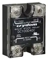
DC100D20C
Solid State Relay, 20 A, 72 VDC, Panel Mount, Screw, DC Switch
⚠️ Reference pricing provided. In case of supply shortages, we will connect you with our trusted procurement partners to ensure your project's continuity.
- Manufacturer: SENSATA/CRYDOM
- Product type:
- Contact Configuration:-; Load Current:20A; Operating Voltage Max:72VDC; Relay Mounting:Panel; Relay Terminals:Screw; Switching Mode:DC Switch; Operating Voltage Min:7VDC; Control Voltage Min:4VDC; Contr
- Load Current: 20A
- Product Range: PowerPlus DC Series
- Relay Mounting: Panel Mount
- Switching Mode: DC Switch
- Relay Terminals: Screw
- Control Voltage Max: 32VDC
- Control Voltage Min: 4VDC
- Contact Configuration: -
- Operating Voltage Max: 72VDC
- Operating Voltage Min: 7VDC
| Delivery and price | |
|---|---|
| Units per pack | 1 |
| Price | 103.79 € |
| Current stock | 10+ |
| Lead time | 30 days |
Datasheet

## **POWERPLUS DC SERIES | 100 VDC** PANEL MOUNT SOLID STATE RELAYS

## Features

- Ratings from 10 A to 100 A @ 100 VDC

- LED Status Indicator

- Relays are easily paralleled for higher-current applications

- UL Approved, CE Compliant to EN60950-1

- Improved SEMS screw and washer

- Redesigned housing with anti-rotation barriers

- MOSFET Output

- DC control

- EMC Compliant to Level 3

- Epoxy Free Design

- Optional IP20 Cover

• PWM up to 1 kHz

## @ **PRODUCT SELECTION**

|**Description**<br>~~=~~|**10 A**<br>~~=~~|**20 A**<br>~~=~~|**40 A**<br>~~=~~|**60 A**<br>~~=~~|**80 A**<br>~~=~~|**100 A**<br>~~=~~|
|---|---|---|---|---|---|---|
|**Recommended Operating Voltage [Vdc]**<br>~~=~~<br>~~——~~|1-72<br>~~=~~|1-72<br>~~=~~<br>~~|||~~|1-72<br>~~=~~<br>~~|||~~|1-72<br>~~=~~<br>~~|||~~|1-72<br>~~=~~<br>~~|||~~|1-72<br>~~=~~<br>~~|||~~|
|**Absolute Maximum Rating [Vdc]**<br>~~=~~<br>~~——~~|100<br>~~=~~|100<br>~~=~~<br>~~|||~~|100<br>~~=~~<br>~~|||~~|100<br>~~=~~<br>~~|||~~|100<br>~~=~~<br>~~|||~~|100<br>~~=~~<br>~~|||~~|
|**Maximum Off-State Leakage Current @ Rated**<br>**Voltage [mA]**<br>~~—~~<br>~~——~~|0.1<br>~~—~~|0.1<br>~~—~~<br>~~|||~~|0.1<br>~~—~~<br>~~|||~~|0.1<br>~~—~~<br>~~|||~~|0.1<br>~~—~~<br>~~|||~~|0.1<br>~~—~~<br>~~|||~~|
|**Maximum Load Current [Adc](2)(3)**<br>~~—~~<br>~~——~~|10<br>~~—~~|20<br>~~—~~<br>~~|||~~|40<br>~~—~~<br>~~|||~~|60<br>~~—~~<br>~~|||~~|80<br>~~—~~<br>~~|||~~<br>~~PT~~|100<br>~~—~~<br>~~|||~~<br>~~PT~~|
|**Minimum Load Current [mA](4)**<br>~~——~~<br>~~=~~<br><br>~~——~~|2.5<br>~~=~~<br><br>|2.5<br>~~|||~~<br>~~=~~<br>~~||~~<br>|2.5<br>~~|||~~<br>~~=~~<br>~~||~~<br>|2.5<br>~~|||~~<br>~~||~~<br>|2.5<br>~~|||~~<br>~~PT~~<br>~~||~~<br>|2.5<br>~~|||~~<br>~~PT~~<br>~~||~~<br>|
|**Maximum Surge Current (10msec) [Adc]**<br>~~——~~<br>~~=~~<br><br>~~——~~|66<br>~~=~~<br><br>|91<br>~~|||~~<br>~~=~~<br>~~||~~<br>|136<br>~~|||~~<br>~~=~~<br>~~||~~<br>|180<br>~~|||~~<br>~~||~~<br>|220<br>~~|||~~<br>~~||~~<br>|330<br>~~|||~~<br>~~||~~<br>|
|**Maximum On-State Voltage Drop @ Rated**<br>**Current [Vdc]**<br>~~—~~<br>~~——~~|0.13<br><br>|0.24<br>~~||~~<br>|0.28<br>~~||~~<br>|0.36<br>~~||~~<br>|0.40<br>~~||~~<br>|0.4<br>~~||~~<br>|
|**Maximum On-State Resistance [RDS-ON] [mΩ]**<br>~~— ~~<br>~~——pot~~|13<br> <br>~~pot~~|12<br> ~~||~~<br>~~pot~~|7<br>~~||~~<br>|6<br>~~||~~<br>|5<br>~~||~~<br>|4<br>~~||~~<br>|
|**Thermal Resistance Junction to Case (Rjc)**<br>**[°C/W]**<br> <br>~~——pot~~|1.27<br> <br>~~pot~~|0.73<br> ~~||~~<br>~~potfT~~|0.58<br>~~||~~<br>~~fT~~|0.45<br>~~||~~<br>~~fT~~|0.34<br>~~||~~<br>~~fT~~|0.27<br>~~||~~<br>~~fT~~|
|**Minimum Heat Sink for Rated Current @ 40°C**<br>**[°C/W]**<br> <br>~~—— pot~~|N/R<br> <br>~~pot~~|5<br> ~~||~~<br>~~potfT~~|2<br>~~||~~<br>~~fT~~|1<br>~~||~~<br>~~fT~~|0.5<br>~~||~~<br>~~fT~~|0.5<br>~~||~~<br>~~fT~~|
|**Maximum Pulse Width Modulation Frequency**<br>**[Hz]5**|1000|1000|900|900|700|700|


Output Voltage[(1)]

Page 1

Copyright © 2024 Sensata Technologies, Inc.

www.sensata.com

Input[(1)]

**==> picture [542 x 155] intentionally omitted <==**

**----- Start of picture text -----**<br>
Description DC Control<br>Control Voltage Range 4-32 VDC<br>Maximum Reverse Voltage -32 VDC<br>Minimum Turn-On Voltage  [(6)] 4 VDC<br>Must Turn-Off Voltage 1 VDC<br>Minimum Input Current (for on-state)  11 mA<br>Maximum Input Current 14 mA<br>Nominal Input Impedance Current Regulated<br>Maximum Turn-On Time [μsec]  75<br>Maximum Turn-Off Time [μsec]  150<br>**----- End of picture text -----**<br>


## General[(1)]

**==> picture [542 x 315] intentionally omitted <==**

**----- Start of picture text -----**<br>
Description Parameters<br>Dielectric Strength, Input/Output/Base (50/60 Hz)  3750 Vrms<br>Minimum Insulation Resistance (@ 500 VDC) 10 [9]  Ohms<br>Maximum Capacitance, Input/Output 8 pF<br>Ambient Operating Temperature Range  [(7)] -40 to 100 °C<br>Ambient Storage Temperature Range -40 to 125 °C<br>Weight (typical) 2.53 oz (72 g)<br>Housing Material UL94 V-0<br>Hardware Finish Nickel Plating<br>Baseplate Material Aluminum<br>Input Terminal Screw Torque Range (lb-in/Nm) 13-15 /1.5-1.7<br>Load Terminal Screw Torque Range (lb-in/Nm) 18-20 / 2-2.2<br>SSR Mounting Screw Torque Range (lb-in/Nm) 18-20 / 2-2.2<br>Input/Load Terminal Screw Torque Range (lb-in/Nm)  [(2)] w/”K” option 8-10 / 0.9-1.13<br>Input/Output Terminal Screw Thread Size #6-32 UNC / #8-32 UNC<br>Humidity per IEC60068-2-78 85% non-condensing<br>LED Input Status Indicator Green<br>MTBF (Mean Time Between Failures) at 40°C ambient<br>21,395,130 hours (2,441 years)<br>temperature  [(8)]<br>MTBF (Mean Time Between Failures) at 60°C ambient<br>11,545,504 hours (1,317 years)<br>temperature  [(8)]<br>**----- End of picture text -----**<br>


Page 2

Copyright © 2024 Sensata Technologies, Inc.

www.sensata.com

## **WIRING DIAGRAM**

* Inductive loads must be diode suppressed.

**==> picture [170 x 165] intentionally omitted <==**

**----- Start of picture text -----**<br>
+ + -<br>V Load * * Load V<br>- + +<br>1 OUTPUT +2 1 OUTPUT +2<br>4 INPUT +3 4 INPUT +3<br>+ +<br>V V<br>- -<br>**----- End of picture text -----**<br>


**==> picture [266 x 163] intentionally omitted <==**

**----- Start of picture text -----**<br>
Recommended Wire Sizes<br>Wire Size   Wire Pull-Out<br>Terminals<br>(Solid / Stranded) Strength (lb)[N]<br>24 AWG (0.2 mm [2] ) /<br>10 [44.5]<br>0.2 [minimum]<br>Input<br>2 x 12 AWG (3.3 mm [2] ) /<br>90 [400]<br>3.3 [maximum]<br>20 AWG (0.5 mm [2] ) /<br>30 [133]<br>0.518 [minimum]<br>Output 2 x 10 AWG (5.3 mm [2] ) / 5.3 110 [490]<br>2 x 8 AWG (8.4 mm [2] ) /<br>90 [400]<br>8.4 [maximum]<br>**----- End of picture text -----**<br>


## **EQUIVALENT CIRCUIT BLOCK DIAGRAMS**

**==> picture [256 x 70] intentionally omitted <==**

**----- Start of picture text -----**<br>
+DC 3 2 +DC<br>Control Trigger<br>Circuit Circuit<br>-DC 4 1 -DC<br>**----- End of picture text -----**<br>


**==> picture [198 x 132] intentionally omitted <==**

**----- Start of picture text -----**<br>
Input Current vs Input Voltage<br>Standard Regulated “DC” Inputs<br>14<br>12<br>10<br>8<br>6<br>4<br>2<br>0<br>05 10 15 20 25 30 35<br>DC Input Voltage<br>Input Current (mA)<br>**----- End of picture text -----**<br>


## **MECHANICAL SPECIFICATIONS[(1)]**

*Tolerances: ±0.02 in / 0.5 mm All dimensions are in: inches [millimeters]

## Screw Termination

## Hex Standoff Termination (“K” Option)[(2)]

**==> picture [518 x 192] intentionally omitted <==**

**----- Start of picture text -----**<br>
1.1 0.89 1.1 1.04<br>[27.9] Mounting  [22.6] [27.9] Mounting  [26.4]<br>0.49 Hole/Slot  0.49 Hole/Slot  (2 places)<br>[12.4] 0.19 [4.9] [12.4] 0.19 [4.9]<br>DIA. DIA.<br>1 OUTPUT +2 1 OUTPUT +2<br>1.88 1.7 2.25 1.88 1.7 2.25<br>[47.6] [43.2] [57.3] [47.6] [43.2] [57.3]<br>4 INPUT +3 4 INPUT +3<br>1.0  1.0  0.93<br>[25.4] [25.4] [23.6]<br>1.75 1.75 (4 places)<br>[44.5] [44.5] 1.0<br>[25.4]<br>(2 places)<br>**----- End of picture text -----**<br>


Page 3

Copyright © 2024 Sensata Technologies, Inc.

www.sensata.com

Screw Termination, IP20

**==> picture [187 x 127] intentionally omitted <==**

## **SURGE CURRENT INFORMATION**

**==> picture [238 x 372] intentionally omitted <==**

**==> picture [239 x 406] intentionally omitted <==**

Page 4

Copyright © 2024 Sensata Technologies, Inc.

www.sensata.com

## **THERMAL DERATE INFORMATION**

(iii) SSR metal base plate acting as heat sink, it must be exposed to free ambient air.

**==> picture [184 x 86] intentionally omitted <==**

**==> picture [183 x 120] intentionally omitted <==**

**==> picture [179 x 116] intentionally omitted <==**

**==> picture [184 x 120] intentionally omitted <==**

**==> picture [183 x 118] intentionally omitted <==**

**==> picture [182 x 117] intentionally omitted <==**

Page 5

Copyright © 2024 Sensata Technologies, Inc.

www.sensata.com

## **ACCESSORIES**

**==> picture [542 x 255] intentionally omitted <==**

**----- Start of picture text -----**<br>
Recommended Accessories<br>Thermal<br>Cover Hardware Kit Heat Sink Part No. Resistance [ºC/W] Lug Terminal Thermal Pad<br>KS101 HK1 HS501DR 5.0 TRM1 HSP-1<br>HK4 HS301 / HS301DR 3.0 TRM6 HSP-2<br>HS251 2.5<br>HS201 / HS201DR 2.0<br>HS202 / HS202DR 2.0<br>HS172 1.7<br>HS151 / HS151DR 1.5<br>HS122 / HS122DR 1.2<br>HS103 / HS103DR 1.0<br>HS101 1.0<br>HS073 0.7<br>HS072 0.7<br>HS053 0.5<br>HS033 0.36<br>HS023 0.25<br>**----- End of picture text -----**<br>


## **ORDERING OPTIONS**

## Example : DC100D40CH

**==> picture [541 x 366] intentionally omitted <==**

**----- Start of picture text -----**<br>
Not all part number combinations are available.<br>Contact Technical Support for information on the availability of a specific part number.<br>DC 100 D 40 K C H<br>Series<br>DC<br>Operating Voltage<br>100:  1-100 VDC<br>Control Voltage<br>D:  4-32 VDC<br>Rated Load Current<br>10:  10 Amps<br>20:  20 Amps<br>40:  40 Amps<br>60:  60 Amps<br>80:  80 Amps<br>100:  100 Amps<br>Termination<br>Blank:  Screws & clamps<br>K:  Installed standoffs with  [(2)]  screws<br>for PC Board mounting (IP00 only)<br>Cover<br>Blank:  Not Included (IP00)<br>C:  Included (IP20)<br>Thermal Pad<br>Blank:  Not Included Required for valid part number<br>H:  Included For options only and not required for valid part number<br>**----- End of picture text -----**<br>


Page 6

Copyright © 2024 Sensata Technologies, Inc.

www.sensata.com

## **GENERAL NOTES**

- **(1) All parameters at Tc=25°C unless otherwise specified.**

- **(2)  Option “K” is designed and tested for use with printed circuit boards or ring/fork terminals having a thickness between 0.031 and 0.093 inches (0.79 to 2.36 mm), and loads rated up to 50 Amps.**

- **For higher load currents, the “K” standoff temperature must not exceed 105°C. For additional application assistance please contact Technical Support.**

- **(3) Heat sinking required, see derating curves.**

- **(4) Low current loads and high ambient temperature can affect turn-on time.**

- **(5) 8 VDC Minimum control voltage. Resistive loads only. Consider switching losses; at maximum frequency reduce to 75% output current.**

- **(6) Increase minimum voltage by 1V for operations from -20 to -40°C.**

- **(7) Decrease maximum control voltage 1.35V/°C above 80°C ambient temperature.**

- **(8) All parameters at 50% power rating and 100% duty cycle.**

For additional information or specific questions, contact Technical Support

## **AGENCY APPROVALS & CERTIFICATIONS**

EN60950-1: Meets the requirements of sections1.5: 1,7: 2.9: 2.10.5.3: 4.2: 4.5: 4.7: IEC 61000-4-2 Electrostatic Discharge Level 3

IEC 61000-4-4 Electrically Fast Transients Level 3 IEC 61000-4-5 Electrical Surges Level 3

E116950

## **WARNINGS**

## RISK OF MATERIAL DAMAGE AND HOT ENCLOSURE

- The product’s side panels may be hot, allow the product to cool before touching • Follow proper mounting instructions including torque values

- Do not allow liquids or foreign objects to enter this product

**Failure to follow these instructions can result in serious injury, or equipment damage.**

HAZARD OF ELECTRIC SHOCK, EXPLOSION OR ARC FLASH

- Disconnect all power before installing or working with this equipment

- Verify all connections and replace all covers before turning on power **Failure to follow these instructions will result in death or serious injury.**

Page 7

Datasheets provided by Sensata Technologies, Inc., its subsidiaries and/or affiliates (“Sensata”) are solely intended to assist third parties

(“Buyers”) who are developing systems that incorporate Sensata products (also referred to herein as “components”). Buyer understands and agrees that Buyer remains responsible for using its independent analysis, valuation, and judgment in designing Buyer’s systems and products. Sensata datasheets have been created using standard laboratory conditions and engineering practices. Sensata has not conducted any testing other than that specifically described in the published documentation for a particular datasheet. Sensata may make corrections, enhancements, improvements, and other changes to its datasheets or components without notice. Buyers are authorized to use Sensata datasheets with the Sensata component(s) identified in each particular datasheet. HOWEVER,

NO OTHER LICENSE, EXPRESS OR IMPLIED, BY ESTOPPEL OR OTHERWISE TO ANY OTHER SENSATA INTELLECTUAL PROPERTY RIGHT, AND NO LICENSE TO ANY THIRD PARTY TECHNOLOGY OR INTELLECTUAL PROPERTY RIGHT, IS GRANTED HEREIN. SENSATA DATASHEETS ARE PROVIDED “AS IS”. SENSATA MAKES NO WARRANTIES OR REPRESENTATIONS WITH REGARD TO THE DATASHEETS OR USE OF THE DATASHEETS, EXPRESS, IMPLIED, OR STATUTORY, INCLUDING ACCURACY OR COMPLETENESS. SENSATA DISCLAIMS

ANY WARRANTY OF TITLE AND ANY IMPLIED WARRANTIES OF MERCHANTABILITY, FITNESS FOR A PARTICULAR PURPOSE, QUIET ENJOYMENT, QUIET POSSESSION, AND NON-INFRINGEMENT OF ANY THIRD PARTY INTELLECTUAL PROPERTY RIGHTS WITH REGARD TO SENSATA DATASHEETS OR USE THEREOF.

All products are sold subject to Sensata’s terms and conditions of sale supplied at www.sensata.com. SENSATA ASSUMES NO LIABILITY FOR APPLICATIONS ASSISTANCE OR THE DESIGN OF BUYERS’ PRODUCTS. BUYER ACKNOWLEDGES AND AGREES THAT IT IS SOLELY RESPONSIBLE FOR COMPLIANCE WITH ALL LEGAL, REGULATORY, AND SAFETY-RELATED REQUIREMENTS CONCERNING ITS PRODUCTS, AND ANY USE OF SENSATA COMPONENTS IN ITS APPLICATIONS, NOTWITHSTANDING ANY APPLICATIONS-RELATED INFORMATION OR SUPPORT THAT MAY BE PROVIDED BY SENSATA.

## **CONTACT US**

## **Americas**

+1(800) 350 2727 sales.crydom@sensata.com

**Europe, Middle East & Africa** +44 (1202) 416170 ssr-info.eu@sensata.com **Asia Pacific** sales.isasia@list.sensata.com China +86 (21) 2306 1500 Japan +81 (45) 277 7117 Korea +82 (31) 601 2004 India +91 (80) 67920890 Rest of Asia +886 (2) 27602006 ext 2808

Mailing Address: Sensata Technologies, Inc., 529 Pleasant Street, Attleboro, MA 02703, USA

Copyright © 2024 Sensata Technologies, Inc.

www.sensata.com

Rev. 07/09/2024 ECN 20395 FDE-07-01 Rev. B
Updated at June 5, 2026
About Novapart
Novapart is a B2B electronic component broker specialising in stock shortages and cost reduction. We source hard-to-find parts and identify compliant alternatives across a catalogue of 410,000+ components from 500+ manufacturers.
Learn more →Stock Shortage Specialist
When a component is unavailable, discontinued or has an unacceptable lead time, we tap into our network of vetted European and Asian distributors to source what you need — without compromising on quality or traceability.
Request a quote →Compliant Alternatives
We identify pin-to-pin, electrically equivalent substitutes that meet the same certifications (RoHS, AEC-Q100, REACH) as your original specification — validated against datasheets, not just part numbers. Often at a lower cost.
BOM Analysis service →