
Image not available
Illustrative purposes only

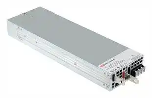
DBU-3200-48
AC/DC Enclosed Power Supply, Chassis Mount, 1 Output, 3200 W, 48 V, 55 A
⚠️ Reference pricing provided. In case of supply shortages, we will connect you with our trusted procurement partners to ensure your project's continuity.
- Manufacturer: MEAN WELL
- Product type: AC / DC Enclosed Power Supplies
- SVHC: No SVHC (25-Jun-2025)
- Product Range: DBU-3200 Series
- No. of Outputs: 1Outputs
- Output Power Max: 3.2kW
- Input Voltage VAC: 90V AC to 264V AC
- Power Supply Output Type: Adjustable, Fixed
- Output Current - Output 1: 55A
- Output Current - Output 2: -
- Output Current - Output 3: -
- Output Current - Output 4: -
- Output Voltage - Output 1: 48VDC
- Output Voltage - Output 2: -
- Output Voltage - Output 3: -
- Output Voltage - Output 4: -
- Power Supply Applications: ITE
| Delivery and price | |
|---|---|
| Units per pack | 1 |
| Price | 578.06 € |
| Current stock | 10+ |
| Lead time | 30 days |
Datasheet

## 3200W Intelligent Single Output Battery Charger **DBU - 3200 series**

mn www.IDBauarSicherheitbeegelod2000000000wacmatuv.comt geprufto ges g ) Adis **UL62368-1 EN62368-1** ~~2~~ **TPTC004** Hl **IEC62368-1** CB CE

## ■

## ■

## ■

## ■

_File Name:DBU-3200-SPEC   2020-03-27_

3200W Intelligent Single Output Battery Charger

## **DBU - 3200 series**

## **SPECIFICATION**

|**DBU-3200-24**<br>**MODEL**<br>**OUTPUT**<br>**VOLTAGE ADJ. RANGE**<br>**VOLTAGE RANGE**<br>**Note.4**<br>**FREQUENCY RANGE**<br>**POWER FACTOR (Typ.)**<br>**EFFICIENCY (Typ.)**<br>**INPUT**<br>**INRUSH CURRENT (Typ.)**<br>**LEAKAGE CURRENT**<br>**AC CURRENT (Typ.)**<br>**Note.4**<br>28.8V<br>27.6V<br>110A<br>23.5 ~ 30V<br>90 ~ 264VAC          127 ~ 370VDC<br>47 ~ 63Hz<br>0.97/230VAC at full load<br>COLD START 55A/230VAC<br>17A/230VAC<br><2mA / 230VAC<br>**DBU-3200-48**<br>57.6V<br>55.2V<br>55A<br>47.5 ~ 58.8V<br>93.5%<br>94.5%<br>**OVER TEMPERATURE**<br>**OVER VOLTAGE**<br>Protection type : Shut down o/p voltage, re-power on to recover<br>Shut down o/p voltage, recovers automatically after temperature goes down<br>31.5 ~ 37.5V<br>63 ~ 75V<br>**PROTECTION**<br>**REMOTE ON-OFF CONTROL**<br>By electrical signal or dry contact     Power ON:short     Power OFF:open. Please refer to the Function Manual<br>**FUNCTION**<br>**WORKING TEMP.**<br>**WORKING HUMIDITY**<br>**VIBRATION**<br>-30 ~ +70<br>(Refer to "Derating Curve")<br>℃<br>20 ~ 90% RH non-condensing<br>±<br>℃<br>℃<br>0.03%/<br>(0 ~ 50<br>)<br>10 ~ 500Hz, 2G 10min./1cycle, 60min. each along X, Y, Z axes<br>**WITHSTAND VOLTAGE**<br>I/P-O/P:3KVAC     I/P-FG:2KVAC     O/P-FG:1.5KVAC<br>**ISOLATION RESISTANCE**<br>**MTBF**<br>**DIMENSION**<br>**PACKING**<br>**OTHERS**<br>160.1K hrs min.<br>Telcordia SR-332 (Bellcore) ; 38.9K hrs min.      MIL-HDBK-217F (25<br>)<br>℃<br>325.8*107*41mm (L*W*H)<br>**SAFETY &**<br>**EMC**<br>**(Note 6)**<br>I/P-O/P, I/P-FG, O/P-FG:100M Ohms / 500VDC / 25<br>/ 70% RH<br>℃<br>2.76Kg;4pcs/12Kg/0.83CUFT<br>**NOTE**<br>**TEMPERATURE COMPENSATION** -3mV /<br>/ cell / (12V = 6 cells ; 24V = 12 cells ; 48V = 24 cells)<br>℃<br>**AUXILIARY POWER**<br>5V @ 0.3A, tolerance<br>10%, ripple 150mVp-p, 12V @ 0.8A, tolerance<br>10%, ripple 450mVp-p<br>±<br>±<br>**BOOST CHARGE  VOLTAGE(Vboost)(default)**<br>**FLOAT CHARGE  VOLTAGE(Vfloat)(default)**<br>By built-in potentiometer, SVR<br>**RECOMMENDED BATTERY**<br>**CAPACITY(AMP HOURS) Note.3** 330 ~ 1000Ah<br>**LEAKAGE CURRENT FROM**<br>1.5mA<br>Adjustment of output voltage is allowable to 75 ~ 125% of nominal output voltage. Please refer to the Function Manual.<br>Adjustment of output voltage is allowable to 20 ~ 100% of rated current. Please refer to the Function Manual.<br>**OUTPUT VOLTAGE PROGRAMMABLE(PV)**<br>**OUTPUT CURRENT PROGRAMMABLE(PC)**<br>**ALARM SIGNAL**<br>Isolated signal output for T-alarm and DC-OK<br>℃<br>℃<br>℃<br>**CONSTANT CURRENT(CC)(default)**<br>**EMC IMMUNITY**<br>**EMC EMISSION**<br>**Parameter**<br>**Parameter**<br>ESD<br>Radiated<br>EFT / Burst<br>Surge<br>Conducted<br>Magnetic Field<br>Voltage Dips and Interruptions<br>Conducted<br>Radiated<br>Harmonic Current<br>Voltage Flicker<br>EN55024 , EN61204-3, EN61000-6-2<br>**Standard**<br>**Standard**<br>EN55032 (CISPR32)<br>EN55032 (CISPR32)<br>EN61000-3-2<br>EN61000-3-3<br>EN61000-4-2<br>EN61000-4-3<br>EN61000-4-4<br>EN61000-6-2<br>EN61000-4-6<br>EN61000-4-8<br>EN61000-4-11<br>**Test Level / Note**<br>**Test Level / Note**<br>Level 3, 8KV air ; Level 2, 4KV contact<br>Level 3<br>Level 3<br>2KV/Line-Line 4KV/Line-Earth<br>Level 3<br>Level 4<br>>95% dip 0.5 periods, 30% dip 25 periods,<br>>95% interruptions 250 periods<br>Class B<br>Class A<br>-----<br>-----<br>**STORAGE TEMP., HUMIDITY**<br>**TEMP. COEFFICIENT**<br>-40 ~ +85<br>, 10 ~ 95% RH non-condensing<br>℃<br>**ENVIRONMENT**<br>**SAFETY STANDARDS**<br>UL62368-1, CSA C22.2<br>, TUV EN62368-1, EAC TP TC 004 approved<br>No. 62368-1<br>18<br>550<br>0 ~<br>Ah<br>**BATTERY (Typ.)**<br>1. Modification for charger specification may be required for different battery specification. Please contact battery vendor and MEAN WELL for details.<br>2. All parameters NOT specially mentioned are measured at230VAC input, rated load and 25 _ of ambient temperature.<br>3. This is MEAN WELL's suggested range. Please consult your battery manufacturer for their suggestions about maximum charging current limitation.<br>4. Derating may be needed under low input voltages. Please check the derating curve for more details.<br>5. The charger is considered a component which will be installed into a final equipment. All the EMC tests are been executed by mounting the unit on<br>a 600mm*900mm metal plate with 1mm of thickness. The final equipment must be re-confirmed that it still meets EMC directives. For guidance on how to<br>perform these EMC tests, please refer to “EMI testing of component power supplies.” (as available on http:/Wwww.meanwell.com)<br>6. The ambient temperature derating of 3.5<br>/1000m with fanless models and of<br>5<br>/1000m with fan models for operating altitude higher than 2000m(6500ft).|**DBU-3200-24**<br>**MODEL**<br>**OUTPUT**<br>**VOLTAGE ADJ. RANGE**<br>**VOLTAGE RANGE**<br>**Note.4**<br>**FREQUENCY RANGE**<br>**POWER FACTOR (Typ.)**<br>**EFFICIENCY (Typ.)**<br>**INPUT**<br>**INRUSH CURRENT (Typ.)**<br>**LEAKAGE CURRENT**<br>**AC CURRENT (Typ.)**<br>**Note.4**<br>28.8V<br>27.6V<br>110A<br>23.5 ~ 30V<br>90 ~ 264VAC          127 ~ 370VDC<br>47 ~ 63Hz<br>0.97/230VAC at full load<br>COLD START 55A/230VAC<br>17A/230VAC<br><2mA / 230VAC<br>**DBU-3200-48**<br>57.6V<br>55.2V<br>55A<br>47.5 ~ 58.8V<br>93.5%<br>94.5%<br>**OVER TEMPERATURE**<br>**OVER VOLTAGE**<br>Protection type : Shut down o/p voltage, re-power on to recover<br>Shut down o/p voltage, recovers automatically after temperature goes down<br>31.5 ~ 37.5V<br>63 ~ 75V<br>**PROTECTION**<br>**REMOTE ON-OFF CONTROL**<br>By electrical signal or dry contact     Power ON:short     Power OFF:open. Please refer to the Function Manual<br>**FUNCTION**<br>**WORKING TEMP.**<br>**WORKING HUMIDITY**<br>**VIBRATION**<br>-30 ~ +70<br>(Refer to "Derating Curve")<br>℃<br>20 ~ 90% RH non-condensing<br>±<br>℃<br>℃<br>0.03%/<br>(0 ~ 50<br>)<br>10 ~ 500Hz, 2G 10min./1cycle, 60min. each along X, Y, Z axes<br>**WITHSTAND VOLTAGE**<br>I/P-O/P:3KVAC     I/P-FG:2KVAC     O/P-FG:1.5KVAC<br>**ISOLATION RESISTANCE**<br>**MTBF**<br>**DIMENSION**<br>**PACKING**<br>**OTHERS**<br>160.1K hrs min.<br>Telcordia SR-332 (Bellcore) ; 38.9K hrs min.      MIL-HDBK-217F (25<br>)<br>℃<br>325.8*107*41mm (L*W*H)<br>**SAFETY &**<br>**EMC**<br>**(Note 6)**<br>I/P-O/P, I/P-FG, O/P-FG:100M Ohms / 500VDC / 25<br>/ 70% RH<br>℃<br>2.76Kg;4pcs/12Kg/0.83CUFT<br>**NOTE**<br>**TEMPERATURE COMPENSATION** -3mV /<br>/ cell / (12V = 6 cells ; 24V = 12 cells ; 48V = 24 cells)<br>℃<br>**AUXILIARY POWER**<br>5V @ 0.3A, tolerance<br>10%, ripple 150mVp-p, 12V @ 0.8A, tolerance<br>10%, ripple 450mVp-p<br>±<br>±<br>**BOOST CHARGE  VOLTAGE(Vboost)(default)**<br>**FLOAT CHARGE  VOLTAGE(Vfloat)(default)**<br>By built-in potentiometer, SVR<br>**RECOMMENDED BATTERY**<br>**CAPACITY(AMP HOURS) Note.3** 330 ~ 1000Ah<br>**LEAKAGE CURRENT FROM**<br>1.5mA<br>Adjustment of output voltage is allowable to 75 ~ 125% of nominal output voltage. Please refer to the Function Manual.<br>Adjustment of output voltage is allowable to 20 ~ 100% of rated current. Please refer to the Function Manual.<br>**OUTPUT VOLTAGE PROGRAMMABLE(PV)**<br>**OUTPUT CURRENT PROGRAMMABLE(PC)**<br>**ALARM SIGNAL**<br>Isolated signal output for T-alarm and DC-OK<br>℃<br>℃<br>℃<br>**CONSTANT CURRENT(CC)(default)**<br>**EMC IMMUNITY**<br>**EMC EMISSION**<br>**Parameter**<br>**Parameter**<br>ESD<br>Radiated<br>EFT / Burst<br>Surge<br>Conducted<br>Magnetic Field<br>Voltage Dips and Interruptions<br>Conducted<br>Radiated<br>Harmonic Current<br>Voltage Flicker<br>EN55024 , EN61204-3, EN61000-6-2<br>**Standard**<br>**Standard**<br>EN55032 (CISPR32)<br>EN55032 (CISPR32)<br>EN61000-3-2<br>EN61000-3-3<br>EN61000-4-2<br>EN61000-4-3<br>EN61000-4-4<br>EN61000-6-2<br>EN61000-4-6<br>EN61000-4-8<br>EN61000-4-11<br>**Test Level / Note**<br>**Test Level / Note**<br>Level 3, 8KV air ; Level 2, 4KV contact<br>Level 3<br>Level 3<br>2KV/Line-Line 4KV/Line-Earth<br>Level 3<br>Level 4<br>>95% dip 0.5 periods, 30% dip 25 periods,<br>>95% interruptions 250 periods<br>Class B<br>Class A<br>-----<br>-----<br>**STORAGE TEMP., HUMIDITY**<br>**TEMP. COEFFICIENT**<br>-40 ~ +85<br>, 10 ~ 95% RH non-condensing<br>℃<br>**ENVIRONMENT**<br>**SAFETY STANDARDS**<br>UL62368-1, CSA C22.2<br>, TUV EN62368-1, EAC TP TC 004 approved<br>No. 62368-1<br>18<br>550<br>0 ~<br>Ah<br>**BATTERY (Typ.)**<br>1. Modification for charger specification may be required for different battery specification. Please contact battery vendor and MEAN WELL for details.<br>2. All parameters NOT specially mentioned are measured at230VAC input, rated load and 25 _ of ambient temperature.<br>3. This is MEAN WELL's suggested range. Please consult your battery manufacturer for their suggestions about maximum charging current limitation.<br>4. Derating may be needed under low input voltages. Please check the derating curve for more details.<br>5. The charger is considered a component which will be installed into a final equipment. All the EMC tests are been executed by mounting the unit on<br>a 600mm*900mm metal plate with 1mm of thickness. The final equipment must be re-confirmed that it still meets EMC directives. For guidance on how to<br>perform these EMC tests, please refer to “EMI testing of component power supplies.” (as available on http:/Wwww.meanwell.com)<br>6. The ambient temperature derating of 3.5<br>/1000m with fanless models and of<br>5<br>/1000m with fan models for operating altitude higher than 2000m(6500ft).|**DBU-3200-24**|**DBU-3200-24**|**DBU-3200-48**|**DBU-3200-48**|
|---|---|---|---|---|---|
||**BOOST CHARGE  VOLTAGE(Vboost)(default)**|28.8V||57.6V||
||**FLOAT CHARGE  VOLTAGE(Vfloat)(default)**|27.6V||55.2V||
||**CONSTANT CURRENT(CC)(default)**|110A||55A||
||**VOLTAGE ADJ. RANGE**|23.5 ~ 30V<br>47.5 ~ 58.8V<br>By built-in potentiometer, SVR||||
||**RECOMMENDED BATTERY**<br>**CAPACITY(AMP HOURS) Note.3**|330 ~ 1000Ah||18<br>550<br>0 ~<br>Ah||
||**LEAKAGE CURRENT FROM**<br>**BATTERY (Typ.)**|1.5mA||||
||**VOLTAGE RANGE**<br>**Note.4**|90 ~ 264VAC          127 ~ 370VDC||||
||**FREQUENCY RANGE**|47 ~ 63Hz||||
||**POWER FACTOR (Typ.)**|0.97/230VAC at full load||||
||**EFFICIENCY (Typ.)**|93.5%||94.5%||
||**AC CURRENT (Typ.)**<br>**Note.4**|17A/230VAC||||
||**INRUSH CURRENT (Typ.)**|COLD START 55A/230VAC||||
||**LEAKAGE CURRENT**|<2mA / 230VAC||||
||**OVER VOLTAGE**|Protection type : Shut down o/p voltage, re-power on to recover<br>31.5 ~ 37.5V<br>63 ~ 75V||||
||**OVER TEMPERATURE**|Shut down o/p voltage, recovers automatically after temperature goes down||||
||**OUTPUT VOLTAGE PROGRAMMABLE(PV)**|Adjustment of output voltage is allowable to 75 ~ 125% of nominal output voltage. Please refer to the Function Manual.||||
||**OUTPUT CURRENT PROGRAMMABLE(PC)**|Adjustment of output voltage is allowable to 20 ~ 100% of rated current. Please refer to the Function Manual.||||
||**AUXILIARY POWER**|5V @ 0.3A, tolerance<br>10%, ripple 150mVp-p, 12V @ 0.8A, tolerance<br>10%, ripple 450mVp-p<br>±<br>±||||
||**REMOTE ON-OFF CONTROL**|By electrical signal or dry contact     Power ON:short     Power OFF:open. Please refer to the Function Manual||||
||**TEMPERATURE COMPENSATION**|-3mV /<br>/ cell / (12V = 6 cells ; 24V = 12 cells ; 48V = 24 cells)<br>℃||||
||**ALARM SIGNAL**|Isolated signal output for T-alarm and DC-OK||||
||**WORKING TEMP.**|-30 ~ +70<br>(Refer to "Derating Curve")<br>℃||||
||**WORKING HUMIDITY**|20 ~ 90% RH non-condensing||||
||**STORAGE TEMP., HUMIDITY**|-40 ~ +85<br>, 10 ~ 95% RH non-condensing<br>℃||||
||**TEMP. COEFFICIENT**|±<br>℃<br>℃<br>0.03%/<br>(0 ~ 50<br>)||||
||**VIBRATION**|10 ~ 500Hz, 2G 10min./1cycle, 60min. each along X, Y, Z axes||||
||**SAFETY STANDARDS**|UL62368-1, CSA C22.2<br>, TUV EN62368-1, EAC TP TC 004 approved<br>No. 62368-1||||
||**WITHSTAND VOLTAGE**|I/P-O/P:3KVAC     I/P-FG:2KVAC     O/P-FG:1.5KVAC||||
||**ISOLATION RESISTANCE**|I/P-O/P, I/P-FG, O/P-FG:100M Ohms / 500VDC / 25<br>/ 70% RH<br>℃||||
||**MTBF**<br>**EMC IMMUNITY**<br>**EMC EMISSION**|**Parameter**|**Standard**||**Test Level / Note**|
|||Conducted|EN55032 (CISPR32)||Class B|
|||Radiated|EN55032 (CISPR32)||Class A|
|||Harmonic Current|EN61000-3-2||-----|
|||Voltage Flicker|EN61000-3-3||-----|
|||EN55024 , EN61204-3, EN61000-6-2||||
|||**Parameter**|**Standard**||**Test Level / Note**|
|||ESD|EN61000-4-2||Level 3, 8KV air ; Level 2, 4KV contact|
|||Radiated|EN61000-4-3||Level 3|
|||EFT / Burst|EN61000-4-4||Level 3|
|||Surge|EN61000-6-2||2KV/Line-Line 4KV/Line-Earth|
|||Conducted|EN61000-4-6||Level 3|
|||Magnetic Field|EN61000-4-8||Level 4|
|||Voltage Dips and Interruptions|EN61000-4-11||>95% dip 0.5 periods, 30% dip 25 periods,<br>>95% interruptions 250 periods|
|||160.1K hrs min.<br>Telcordia SR-332 (Bellcore) ; 38.9K hrs min.      MIL-HDBK-217F (25<br>)<br>℃||||
||**DIMENSION**|325.8*107*41mm (L*W*H)||||
||**PACKING**<br>2.76Kg;4pcs/12Kg/0.83CUFT<br>℃<br>℃<br>℃<br>1. Modification for charger specification may be required for different battery specification. Please contact battery vendor and MEAN WELL for details.<br>2. All parameters NOT specially mentioned are measured at230VAC input, rated load and 25 _ of ambient temperature.<br>3. This is MEAN WELL's suggested range. Please consult your battery manufacturer for their suggestions about maximum charging current limitation.<br>4. Derating may be needed under low input voltages. Please check the derating curve for more details.<br>5. The charger is considered a component which will be installed into a final equipment. All the EMC tests are been executed by mounting the unit on<br>a 600mm*900mm metal plate with 1mm of thickness. The final equipment must be re-confirmed that it still meets EMC directives. For guidance on how to<br>perform these EMC tests, please refer to “EMI testing of component power supplies.” (as available on http:/Wwww.meanwell.com)<br>6. The ambient temperature derating of 3.5<br>/1000m with fanless models and of<br>5<br>/1000m with fan models for operating altitude higher than 2000m(6500ft).|||||


_File Name:DBU-3200-SPEC   2020-03-27_

## 3200W Intelligent Single Output Battery Charger

## **DBU - 3200 series**

## **BLOCK DIAGRAM**

**==> picture [496 x 404] intentionally omitted <==**

**----- Start of picture text -----**<br>
PFC fosc : 110KHz<br>PWM fosc : 90KHz<br>I/P FILTEREMI CURRENTLIMITINGINRUSHACTIVE RECTIFIERSPFC& SWITCHINGPOWER RECTIFIERSFILTER& ORINGFET -V+V<br>DETECTION<br>CIRCUIT ORING  FET<br>CONTROL<br>O.V.P.<br>DETECTION PV/PC<br>CIRCUIT MCU O.T.P.<br>TRANSCEIVERS DA/DB<br>T-Alarm<br>O.T.P. MCU DATA<br>ISOLATION DC-OK<br>AUX FAN SDA/SCL<br>POWER AUX. POWER (CANH/CANL)<br>RECTIFIERS<br>& 5V/0.3A Remote ON-OFF<br>FILTER 12V/0.8A<br>DERATING CURVE STATIC CHARACTERISTICS<br>100<br>100<br>90<br>80 80<br>230VAC<br>Input only 70<br>60<br>50 60<br>40 50<br>40<br>20<br>30<br>-30 -25 -10 0 15 30 50 60 70 (HORIZONTAL) 90 100 115 180 264<br>AMBIENT TEMPERATURE (℃) INPUT VOLTAGE (VAC) 60Hz<br>LOAD (%) LOAD (%)<br>**----- End of picture text -----**<br>


_File Name:DBU-3200-SPEC   2020-03-27_

**DBU - 3200 series**

## 3200W Intelligent Single Output Battery Charger

## **FUNCTION MANUAL**

## **1.PMBus Communication Interface**

- DBU-3200 supports PMBus Rev. 1.1 with maximum 100KHz bus speed, allowing information reading, status monitoring, output trimming, etc. For details, please refer to the Installation Manual.

## **2.Charging Curve**

- ※ By factory default, this charger performs the default curve which can be programmed via PMBus.

- ※ To disable / enable the charging curve, change to a 2 stage curve, a different curve frequently used for certain types of batteries in the industry, and so on, please refer to the Installation Manual.

- ※ To program the parameters of the charging curve, SBP-001, the smart battery charging programmer designed by MEAN WELL, and a personal computer are needed. Please contact MEAN WELL for details.

   - Default 3 stage charging curve ◎ Embedded 3 stage charging curves

**==> picture [468 x 160] intentionally omitted <==**

**----- Start of picture text -----**<br>
3 Stage MODEL Description Vboost Vfloat CC(default)<br>Start Default, programmable 28.8 27.6<br>Vboost<br>Vfloat 24V Pre-defined, gel batter 28 27.2 110A<br>Charge Voltage Pre-defined, flooded battery 28.4 26.8<br>Pre-defined, AGM battery 29 27<br>100% Default, programmable 57.6 55.2<br>Pre-defined, gel batter 56 54.4<br>48V 55A<br>Charge Current Constant Current Constant Voltage Float 10% Pre-defined, flooded battery 56.8 53.6<br>Pre-defined, AGM battery 58 54<br>stage 1 stage 2 stage 3<br>Note:<br>Color of  LED Orange Green<br>When using this charger unit, please configured the system with recommended<br>Status Indicator Charger fail if charging time<br>exceed charging timeout battery capacity defined by specification . Should battery capacity in use be<br>Suitable for lead-acid batteries (flooded, Gel and AGM) and much smaller so that user needs to set a low current for charging, under such<br>Li-ion batteries (lithium iron and lithium manganese). condition it might cause higher current ripple.<br>**----- End of picture text -----**<br>


- Suitable for lead-acid batteries (flooded, Gel and AGM) and Li-ion batteries (lithium iron and lithium manganese).

## **3. Front Panel LED Indicators & Corresponding Signal at Function Pins**

LED Description Green Float (stage 3) Orange Charging (stage 1 or stage 2) Red The LED will present a constant red light when the abnormal status (OTP, OLP, fan fail and charging timeout) arises. The LED will flash with the red light when the internal temperature reaches 60℃; under this condition, the unit still operates normally Red (Flashing) without entering OTP. (In the meantime, an alarm signal will be sent out through the PMBus interface.)

**4. Output Voltage Programming (or, PV / remote voltage programming / remote adjust / margin programming / dynamic voltage trim)** ※ In addition to the adjustment via the built-in potentiometer, the output voltage can be trimmed by applying EXTERNAL VOLTAGE.

**==> picture [243 x 211] intentionally omitted <==**

**----- Start of picture text -----**<br>
PIN12 PV PIN14 -V-signal<br>-V CN1 +V<br>EXTERNAL VOLTAGE (DC)<br>DBU-3200-48 DBU-3200-24<br>60 30<br>Non-Linear<br>48 24<br>36 18<br>V<br>0 0 0.4 1 4.7 5<br>EXTERNAL VOLTAGE (DC)<br>OUTPUT  VOLTAGE(V)<br>**----- End of picture text -----**<br>


_File Name:DBU-3200-SPEC   2020-03-27_

**DBU - 3200 series**

3200W Intelligent Single Output Battery Charger

## **5. Output Current Programming (or, PC / remote current programming / dynamic current trim)**

※ The output current can be trimmed to 20~100% of the rated current by applying EXTERNAL VOLTAGE.

**==> picture [424 x 284] intentionally omitted <==**

**----- Start of picture text -----**<br>
Iout<br>100<br>Non-Linear<br>PIN11 PC PIN14 -V-signal<br>-V CN1 +V<br>EXTERNAL VOLTAGE (DC)<br>20<br>V<br>0.4 1 4.7 5<br>EXTERNAL VOLTAGE (VDC)<br>The power supply can be turned ON/OFF individually or along with other units in parallel by using the "Remote ON-OFF" function.<br>PIN3 +5V-AUX switch Between Remote ON-OFF and +5V-AUX Power Supply Status<br>Switch Short ON<br>Switch Open OFF<br>PIN4 Remote  ON-OFF<br>OUTPUT CURRENT (%)<br>**----- End of picture text -----**<br>


## **6. Remote ON-OFF Control**

The power supply can be turned ON/OFF individually or along with other units in parallel by using the "Remote ON-OFF" function.

**==> picture [202 x 50] intentionally omitted <==**

**----- Start of picture text -----**<br>
PIN3 +5V-AUX switch<br>PIN4 Remote  ON-OFF<br>-V CN1 +V<br>**----- End of picture text -----**<br>


## **7.Temperature Compensation**

**==> picture [444 x 142] intentionally omitted <==**

**----- Start of picture text -----**<br>
PIN15 RTH+ ◎ To exploit the temperature compensation function, please attach<br>NTC the temperature sensor, NTC, which is enclosed with the charger,<br>to the battery or the battery's vicinity.<br>PIN16 RTH- ◎ The charger is able to work normally without the NTC.<br>-V CN1 +V<br>15 When multiple chargers are connected in parallel, please configure with the NTC<br>Unit 1 NTC as exhibited in the diagram .<br>16 If the temperature compensation is not required, RTH+ (PIN15) and RTH- (PIN16)<br>from each unit still need to be connected.<br>15<br>Unit 2<br>16<br>**----- End of picture text -----**<br>


## **8. Alarm Signal Output**

- ※ There are 2 alarm signals, DC OK and T-ALARM, in TTL signal form, on CN1. These signals are isolated from output. The maximum sink current is 10mA.

**==> picture [291 x 59] intentionally omitted <==**

**----- Start of picture text -----**<br>
PIN5 DC OK<br>Application<br>Circuit<br>PIN6 T-ALARM<br>-V CN1 +V PIN2 GND-AUX<br>**----- End of picture text -----**<br>


_File Name:DBU-3200-SPEC   2020-03-27_

**DBU - 3200 series**

3200W Intelligent Single Output Battery Charger

## **9.Current Sharing**

- DBU-3200 has the built-in active current sharing function and can be connected in parallel, up to 2 units, to provide higher output power as exhibited below : ※ The power supplies to be paralleled should use short and large diameter wiring and then connected to the load. ※ Difference of output voltages among parallel units should be less than 0.2V. ※ The total output current must not exceed the value calculated by the following equation: Maximum output current at parallel operation=(Rated current per unit)×(Number of unit)×0.9

- **※** When the total output current is less than 5% of the total rated current, or say (5% of Rated current per unit)×(Number of unit) the current shared among units may not be balanced.

- ※ CN500/SW1 Function pin connection

|Parallel|PSU1|PSU1|PSU2|PSU2|
|---|---|---|---|---|
||CN500|SW1|CN500|SW1|
|1 unit|X|ON|∣|∣|
|2 unit|V|ON|V|ON|


(V : CN500 connected ; X : CN500 not connected.)

**==> picture [192 x 285] intentionally omitted <==**

**----- Start of picture text -----**<br>
DBU-3200 DBU-3200<br>PSU1 PSU2<br>-V -V<br>+V TB1 +V TB1<br>-V +V<br>LOAD<br>Fig 5.1<br>6 4 2 6 4 2<br>-V(signal) DB DA -V(signal) DB DA<br>-V(signal) DB DA -V(signal) DB DA<br>5 3 1 5 3 1<br>PSU1 CN500 PSU2 CN500<br>If the lines of CN500 are too long, they should<br>be twisted in pairs to avoid the noise.<br>**----- End of picture text -----**<br>


◎ DA,DB and -V(signal) are connected mutually in parallel.

_File Name:DBU-3200-SPEC   2020-03-27_

**DBU - 3200 series**

3200W Intelligent Single Output Battery Charger

## **MECHANICAL SPECIFICATION**

**==> picture [448 x 736] intentionally omitted <==**

**----- Start of picture text -----**<br>
Case No.256         Unit:mm<br>30 6.25 276<br>2-M4  L=5<br>21<br>2 2<br>28<br>-V<br>38<br>Air flow<br>+V direction<br>SVR (TOP View)<br>LED SW1<br>1<br>2 I/P<br>3<br>2 2<br>2-M4  L=5<br>2-M3<br>12 max.<br>6.25 276<br>325.8<br>1<br>1<br>(Bottom View)<br>3-M3 L=4<br>1<br>16 46 241.5<br>Chassis of DBU-3200<br>※ Mounting Instruction Mounting Surface<br>Hole No. Recommended Screw Size MAX. Penetration Depth  L Recommended mounting torque<br>1 M3 6mm 6~8Kgf-cm<br>2 M4 7mm 7~10Kgf-cm<br>Mounting Screw<br>※Control Pin No. Assignment(CN1) : HRS DF11-16DP-2DS or equivalent<br>1 15<br>Mating Housing HRS DF11-16DS or equivalent<br>Terminal HRS DF11-**SC or equivalent<br>2 16<br>Pin No. Function Description<br>1 +12V-AUX Auxiliary voltage output, 10.6~13.2V, referenced to GND-AUX (pin2).<br>The maximum load current is 0.8A. This output has the built-in "Oring diodes" and is not controlled by “Remote ON-OFF”.<br>2 GND-AUX Auxiliary voltage output GND.<br>The signal return is isolated from the output terminals (+V & -V).<br>3 +5V-AUX Auxiliary voltage output, 4.5~5.5V, referenced to GND-AUX (pin2).<br>The maximum load current is 0.3A. This output has the built-in "Oring diodes" and is not controlled by “Remote ON-OFF<br>4 Remote The unit can turn the output ON/OFF by electrical signal or dry contact between Remote ON/OFF and +5V-AUX . (Note.2)<br>ON-OFF Short (4.5 ~ 5.5V) : Power ON ; Open (-0.1 ~ 0.5V) : Power OFF ; The maximum input voltage is 5.5V.<br>High (4.5 ~ 5.5V) : When the Vout ≦16V/32V ±1V.<br>5 DC-OK Low (-0.1 ~ 0.5V) : When Vout ≧16V/32V ±1V. The maximum sourcing current is 10mA and only for output. (Note.2)<br>DC OK  is associated with battery low protection.<br>High (4.5 ~ 5.5V) : When the internal temperature exceeds the limit of temperature alarm, or when Fan fails.<br>6 T-ALARM Low (-0.1 ~ 0.5V) : When the internal temperature is normal, and when Fan works normally.<br>The maximum sourcing current is 10mA and only for output(Note.2)<br>7,8,9 A0,A1,A2 PMBus interface address lines. (Note.1)<br>10 D0 DIP-switch interface lines for charging curve selection. (Note.1)<br>11 PC Connection for output current programming. (Note.1)<br>12 PV Connection for output voltage programming. (Note.1)<br>13 +V (Signal) Positive output voltage signal.<br>It cannot be connected directly to the load.<br>14 -V (Signal) Negative output voltage signal.<br>It is for certain function reference; it cannot be connected directly to the load.<br>15 RTH+ Temperature sensor(NTC, 5KOhm) comes along with the charger can be connected to the unit to allow temperature<br>16 RTH- compensation of the charging voltage.<br>Note1: Non-isolated signal, referenced to the [-V(signal)].<br>Note2: Isolated signal, referenced to GND-AUX.<br>ψ<br>6.5<br>9<br>29.6 21.6 22.8<br>2<br>107<br>10<br>13 41<br>22.8<br>97.9<br>53.5<br>6.9<br>2 1<br>CN1<br>16 5 1<br>8 2<br>CN500 7 1<br>**----- End of picture text -----**<br>


_File Name:DBU-3200-SPEC 2020-03-27_

**DBU - 3200 series**

## 3200W Intelligent Single Output Battery Charger

※AC Input Terminal Pin No. Assignment Pin No. Assignment Diagram Maximum mounting torque 1 FG 1 2 3 2 AC/N 8Kgf-cm 3 AC/L ※Control Pin No. Assignment(CN500) : HRS DF11-8DP-2DS or equivalent 8 2 Mating Housing HRS DF11-8DS or equivalent Terminal HRS DF11-**SC or equivalent 7 1 **Pin No. Function Description** 1, 2 DA Differential digital signal for parallel control. 3, 4 DB Differential digital signal for parallel control. Negative output voltage signal. 5, 6 -V (Signal) It is for local sense; and certain function reference; it cannot be connected directly to the load. NC For standard model: None. 7 SDA For PMBus model: Serial Data used in the PMBus interface. (Note) CANH For CANBus model: Data line used in CANBus interface. (Note) NC For standard model: None. 8 SCL For PMBus model: Serial Clock used in the PMBus interface. (Note) CANL For CANBus model: Data line used in CANBus interface. (Note) Note: Isolated signal, referenced to GND-AUX. ※Control Pin No. Assignment.(SW1) **Pin No. Function Description** Terminal 1, 2 resistance SW1 is the selector of terminal resistor that is designed for DA/DB signals and parallel control function.

## **INSTALLATION MANUAL**

Please refer to : http://www.meanwell.com/manual.html

_File Name:DBU-3200-SPEC   2020-03-27_
Updated at June 6, 2026
About Novapart
Novapart is a B2B electronic component broker specialising in stock shortages and cost reduction. We source hard-to-find parts and identify compliant alternatives across a catalogue of 410,000+ components from 500+ manufacturers.
Learn more →Stock Shortage Specialist
When a component is unavailable, discontinued or has an unacceptable lead time, we tap into our network of vetted European and Asian distributors to source what you need — without compromising on quality or traceability.
Request a quote →Compliant Alternatives
We identify pin-to-pin, electrically equivalent substitutes that meet the same certifications (RoHS, AEC-Q100, REACH) as your original specification — validated against datasheets, not just part numbers. Often at a lower cost.
BOM Analysis service →