


DA14580-01A31
MCU, Bluetooth, ARM Cortex-M0, 16 MHz, 32 bit, 50 KB RAM/116 KB Program, I2C, SPI, UART, QFN-48
- Manufacturer: RENESAS
- Product type: Bluetooth Modules & Adaptors
- Product Range:ARM Cortex-M0 Microcontrollers; Architecture:ARM Cortex-M0; MCU Core Size:32bit; Program Memory Size:116KB; RAM Memory Size:50KB; CPU Speed:16MHz; No. of I/O's:32I/
- MSL: MSL 3 - 168 hours
- SVHC: No SVHC (12-Jan-2017)
- Interfaces: I2C, SPI, UART
- MCU Family: SmartBond
- MCU Series: DA1458x
- Device Core: ARM Cortex-M0
- IC Mounting: Surface Mount
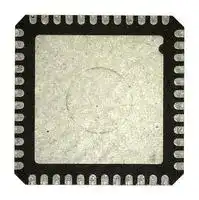
- No. of Pins: 48Pins
- ADC Channels: 4Channels
- Product Range: DA14580 Series Microcontrollers
- ADC Resolution: 10Bit
- Data Bus Width: 32 bit
- RAM Memory Size: 50KB
- IC Case / Package: QFN
- Program Memory Size: 116KB
- Supply Voltage Range: 900 mV to 3.3 V
- Operating Frequency Max: 16MHz
- Operating Temperature Range: -40 °C to 85 °C
| Delivery and price | |
|---|---|
| Units per pack | 50 |
| Price | 1.32 € |
| Current stock | 10+ |
| Lead time | 30 days |
**DA14580**
**FINAL**
## **Low Power Bluetooth Smart 4.2 SoC**
## **General description**
The DA14580 integrated circuit has a fully integrated radio transceiver and baseband processor for _Bluetooth[®] Smart_ . It can be used as a standalone application processor or as a data pump in hosted systems.
The DA14580 supports a flexible memory architecture for storing Bluetooth profiles and custom application code, which can be updated over the air (OTA). The qualified _Bluetooth Smart_ protocol stack is stored in a dedicated ROM. All software runs on the ARM[®] Cortex[®] -M0 processor via a simple scheduler.
The _Bluetooth Smart_ firmware includes the L2CAP service layer protocols, Security Manager (SM), Attribute Protocol (ATT), the Generic Attribute Profile (GATT) and the Generic Access Profile (GAP). All profiles published by the Bluetooth SIG as well as custom profiles are supported.
The transceiver interfaces directly to the antenna and is fully compliant with the _Bluetooth 4.2_ standard.
The DA14580 has dedicated hardware for the Link Layer implementation of _Bluetooth Smart_ and interface controllers for enhanced connectivity capabilities.
## **Features**
- Complies with _Bluetooth_ V4.2, ETSI EN 300 328 and EN 300 440 Class 2 (Europe), FCC CFR47 Part 15 (US) and ARIB STD-T66 (Japan)
- Processing power
- 16 MHz 32 bit ARM Cortex-M0 with SWD interface
- Dedicated Link Layer Processor
- AES-128 bit encryption Processor
- Memories
- 32 kB One-Time-Programmable (OTP) memory
- 84 kB ROM
- 8 kB Retention SRAM
- Power management
- Integrated Buck/Boost DC-DC converter
- P0, P1, P2 and P3 ports with 3.3 V tolerance
- Easy decoupling of only 4 supply pins
- Supports coin (typ. 3.0 V) and alkaline (typ. 1.5 V) battery cells
- 10-bit ADC for battery voltage measurement
- Digital controlled oscillators
- 16 MHz crystal (±20 ppm max) and RC oscillator
- 32 kHz crystal (±50 ppm, ±500 ppm max) and RCX oscillator
- General purpose, Capture and Sleep timers
- Digital interfaces
- General purpose I/Os: 14 (WLCSP34 package), 24 (QFN40 package), 32 (QFN48 package)
- 2 UARTs with hardware flow control up to 1 MBd
- SPI+™ interface
- I2C bus at 100 kHz, 400 kHz
- 3-axes capable Quadrature Decoder
- Analog interfaces
- 4-channel 10-bit ADC
- Radio transceiver
- Fully integrated 2.4 GHz CMOS transceiver
- Single wire antenna: no RF matching or RX/TX switching required
- Supply current at VBAT3V: TX: 3.4 mA, RX: 3.7 mA (with ideal DC-DC)
- 0 dBm transmit output power
- -20 dBm output power in “Near Field Mode”
- -93 dBm receiver sensitivity
- Packages:
- WLCSP 34 pins, 2.436 mm x 2.436 mm
- QFN 40 pins, 5 mm x 5 mm
- QFN 48 pins, 6 mm x 6 mm
- KGD (wafer, dice)
- 42 kB System SRAM
________________________________________________________________________________________________
## **System diagram**
**Revision 3.3**
**08-Jun-2016**
**Datasheet**
CFR0011-120-00-FM
1 of 155
© 2014 Dialog Semiconductor
**DA14580**
**FINAL**
**Low Power Bluetooth Smart 4.2 SoC**
## **Contents**
**==> picture [219 x 604] intentionally omitted <==**
**----- Start of picture text -----**<br>
|||
|---|---|
|General description . . . . . . . . . . . . . . . . . . . . . . . . . . . 1|
|Features . . . . . . . . . . . . . . . . . . . . . . . . . . . . . . . . . . . . . 1|
|System diagram . . . . . . . . . . . . . . . . . . . . . . . . . . . . . . 1|
|Contents. . . . . . . . . . . . . . . . . . . . . . . . . . . . . . . . . . . . . 2|
|1|Block diagram . . . . . . . . . . . . . . . . . . . . . . . . . . . . . . 3|
|2|Pinout . . . . . . . . . . . . . . . . . . . . . . . . . . . . . . . . . . . . . 4|
|3|Ordering information . . . . . . . . . . . . . . . . . . . . . . . . 8|
|4|System overview . . . . . . . . . . . . . . . . . . . . . . . . . . . . 9|
|4.1|ARM CORTEXM0 CPU. . . . . . . . . . . . . . . . . . 9|
|4.2|BLUETOOTH SMART. . . . . . . . . . . . . . . . . . . . 9|
|4.2.1|BLE Core . . . . . . . . . . . . . . . . . . . . . . . . . 9|
|4.2.2|Radio Transceiver . . . . . . . . . . . . . . . . . 10|
|4.2.3|SmartSnippets|
|4.3|MEMORIES. . . . . . . . . . . . . . . . . . . . . . . . . . . .11|
|4.4|FUNCTIONAL MODES . . . . . . . . . . . . . . . . . . .11|
|4.5|POWER MODES. . . . . . . . . . . . . . . . . . . . . . . 12|
|4.6|INTERFACES . . . . . . . . . . . . . . . . . . . . . . . . . 12|
|4.6.1|UARTs . . . . . . . . . . . . . . . . . . . . . . . . . . 12|
|4.6.2|SPI+. . . . . . . . . . . . . . . . . . . . . . . . . . . . 12|
|4.6.3|I2C interface . . . . . . . . . . . . . . . . . . . . . 12|
|4.6.4|General purpose ADC . . . . . . . . . . . . . . 13|
|4.6.5|Quadrature decoder. . . . . . . . . . . . . . . . 13|
|4.6.6|Keyboard controller . . . . . . . . . . . . . . . . 13|
|4.6.7|Input/output ports. . . . . . . . . . . . . . . . . . 13|
|4.7|TIMERS. . . . . . . . . . . . . . . . . . . . . . . . . . . . . . 13|
|4.7.1|General purpose timers . . . . . . . . . . . . . 13|
|4.7.2|Wake-Up timer. . . . . . . . . . . . . . . . . . . . 14|
|4.7.3|Watchdog timer . . . . . . . . . . . . . . . . . . . 14|
|4.8|CLOCK/RESET . . . . . . . . . . . . . . . . . . . . . . . . 14|
|4.8.1|Clocks . . . . . . . . . . . . . . . . . . . . . . . . . . 14|
|4.8.2|Reset . . . . . . . . . . . . . . . . . . . . . . . . . . . 15|
|4.9|POWER MANAGEMENT . . . . . . . . . . . . . . . . 15|
|5|Registers . . . . . . . . . . . . . . . . . . . . . . . . . . . . . . . . . 18|
|6|Specifications . . . . . . . . . . . . . . . . . . . . . . . . . . . . 139|
|7|Package information. . . . . . . . . . . . . . . . . . . . . . . 151|
|7.1|MOISTURE SENSITIVITY LEVEL (MSL) . . . 151|
|7.2|WLCSP HANDLING . . . . . . . . . . . . . . . . . . . 151|
|7.3|SOLDERING INFORMATION . . . . . . . . . . . . 151|
|7.4|PACKAGE OUTLINES . . . . . . . . . . . . . . . . . 152|
**----- End of picture text -----**<br>
**Revision 3.3**
**08-Jun-2016**
**Datasheet**
CFR0011-120-00-FM
2 of 155
© 2014 Dialog Semiconductor
**DA14580**
**FINAL**
**Low Power Bluetooth Smart 4.2 SoC**
**==> picture [670 x 475] intentionally omitted <==**
**----- Start of picture text -----**<br>
1 Block diagram<br>24 April 2012<br>DCDC<br>ARM Cortex M0<br>XTAL XTAL (BUCK/BOOST) RC RC RCX<br>16 MHz 32 kHz<br>32.768 kHz 16 MHz<br>LDO LDO LDO LDO<br>LDO<br>CORE SYS RET SYSSYS<br>RF POReset<br>BLE Core<br>SWD (JTAG)<br>Radio<br>LINK LAYER<br>OS System/ AES-128 HARDWARE Transceiver<br>Exchange<br>RAM<br>42 KB<br>Ret. RAM<br>2 KB<br>Ret. RAM2<br>3 KB<br>Ret. RAM3<br>2 KB<br>Ret. RAM4 SW TIMER<br>1 KB<br>OTP DMA Timer 0<br>1xPWM<br>32 KB<br>OTPC<br>Timer 2<br>ROM 3xPWM GPIO MULTIPLEXING<br>84 KB 0) LLL<br>Figure 1: DA14580 block diagram<br>Datasheet Revision 3.3 08-Jun-2016<br>APB bridge<br>Memory Controller<br>SPI I2C<br>TIMER CTRL UART UART2 GP ADC QUAD<br>WAKE UP DECODER<br>KEYBOARD<br>FIFO FIFO FIFO<br>POWER/CLOCK<br>Management (PMU)<br>**----- End of picture text -----**<br>
CFR0011-120-00-FM
3 of 155
© 2014 Dialog Semiconductor
**DA14580**
**FINAL**
**Low Power Bluetooth Smart 4.2 SoC**
## **2 Pinout**
The DA14580 comes in three packages:
- Wafer Level Chip Scale Package (WLCSP) with 34 balls
- Quad Flat Package No Leads (QFN) with 48 pins
- • Quad Flat Package No Leads (QFN) with 40 pins The actual pin/ball assignment is depicted in the following figures:
**==> picture [197 x 174] intentionally omitted <==**
**----- Start of picture text -----**<br>
1 2 3 4 5 6<br>A , a \ —_<br>B _X vA oN\ ) (—} . ~ 7 -<br>C<br>D _} oN ;a . yr—~ mS~ a<br>E _( oN; , F—1 ¢—~ q ~ “Sy wo.<br>F -_ _ aa coy -<br>RFIOm RFIOp GND VPP<br>XTAL16MmVDCDC_RF<br>P1_3 GND P0_1 P0_0<br>XTAL16Mp<br>P1_2 GND P0_2 P0_3<br>SW_CLK<br>SWDIO P1_1 GND GND P0_4 P0_5<br>VBAT1V P1_0 RST VBAT_RF P0_7 P0_6<br>SWITCH VDCDC GND VBAT3V XTAL32Kp XTAL32Km<br>**----- End of picture text -----**<br>
**Figure 2: WLCSP34 ball assignment**
**==> picture [293 x 260] intentionally omitted <==**
**----- Start of picture text -----**<br>
P0_0 1 36 I P3_6<br>P0_1 td 2 35 - XTAL16Mm<br>P0_2 pot‘a-----! 3 yVaiaieatateatateaeed ——- 34 al~ - XTAL16Mp<br>P0_3 1 -----!H 4 7| 33 P1_3<br>P3_0 5 32 a P1_2<br>P0_4 H ----4!H 6 || DA14580 31 — SW_CLK<br>P0_5 -----! 7 | (Top View) 30 — SWDIO<br>P2_1 1 -i 8 | | 29 pooeee— P1_1<br>P0_6 _----! 9 | 28 VBAT1V<br>| peoeee<br>P3_1 "| 10 ! 27 —— P1_0<br>P0_7 —----! 11 TE 26 — SWITCH<br>P3_2 ----! 12 25 _ P3_5<br>fe' erFe eree eeer<br>tid<br>Pin 0: GND plane<br>P2_0 P2_9 VPP P2_8 P2_7 NC RFIOp RFIOm P3_7 P2_6 P2_5 VDCDC_RF<br>48 47 46 45 44 43 42 41 40 39 38 37<br>13 14 15 16 17 18 19 20 21 22 23 24<br>XTAL32Km XTAL32Kp P3_3 P2_2 VBAT_RF P3_4 VBAT3V GND RST P2_3 VDCDC P2_4<br>**----- End of picture text -----**<br>
**Figure 3: QFN48 pin assignment**
**Revision 3.3**
**08-Jun-2016**
**Datasheet**
CFR0011-120-00-FM
4 of 155
© 2014 Dialog Semiconductor
**DA14580**
**FINAL**
**Low Power Bluetooth Smart 4.2 SoC**
**==> picture [270 x 257] intentionally omitted <==**
**----- Start of picture text -----**<br>
P0_0 — 1 pone ee, 30 — XTAL16Mm<br>P0_1 2 / | 29 i XTAL16Mp<br>____| J bo<br>P0_2 — 3 7) l 28 | P1_3<br>P0_3 wt— 4 | oebo 27 P1_2<br>NC 5 DA14580 26 SW_CLK<br>wa | pe<br>P0_4 —----4_o , 6 || (Top View) ; 25 —_= SWDIO<br>| pone<br>P0_5 -----! 7 | l 24 __ P1_1<br>P2_1 a 8 | 23 VBAT1V<br>be<br>P0_6 ee 9 | | 22 P1_0<br>P0_7 a 10 21 SWITCH<br>Pin 0: GND<br>plane<br>P2_0 P2_9 VPP P2_8 P2_7 RFIOp RFIOm P2_6 P2_5 VDCDC_RF<br>40 39 38 37 36 35 34 33 32 31<br>11 12 13 14 15 16 17 18 19 20<br>XTAL32Km XTAL32Kp P2_2 VBAT_RF VBAT3V GND RST P2_3 VDCDC P2_4<br>**----- End of picture text -----**<br>
**Figure 4: QFN40 pin assignment**
**Table 1: Pin Description**
|**PIN NAME**|**TYPE**|**Drive**<br>**(mA)**|**Reset**<br>**state**<br>**(Note )**|**DESCRIPTION**|
|---|---|---|---|---|
|**General Purpose I/Os**|||||
|P0_0<br>P0_1<br>P0_2<br>P0_3<br>P0_4<br>P0_5<br>P0_6<br>P0_7|DIO<br>DIO<br>DIO<br>DIO<br>DIO<br>DIO<br>DIO<br>DIO|4.8|I-PD<br>I-PD<br>I-PD<br>I-PD<br>I-PD<br>I-PD<br>I-PD<br>I-PD|INPUT/OUTPUT with selectable pull up/down resistor. Pull-down<br>enabled during and after reset. General purpose I/O port bit or<br>alternate function nodes. Contains state retention mechanism<br>during power down.|
|P1_0<br>P1_1<br>P1_2<br>P1_3<br>P1_4/SWCLK<br>P1_5/SW_DIO|DIO<br>DIO<br>DIO<br>DIO<br>DIO<br>DIO|4.8|I-PD<br>I-PD<br>I-PD<br>I-PD<br>I-PD<br>I-PU|INPUT/OUTPUT with selectable pull up/down resistor. Pull-down<br>enabled during and after reset. General purpose I/O port bit or<br>alternate function nodes. Contains state retention mechanism<br>during power down.<br>This signal is the JTAG clock by default<br>This signal is the JTAG data I/O by default|
|P2_0<br>P2_1<br>P2_2<br>P2_3<br>P2_4<br>P2_5<br>P2_6<br>P2_7<br>P2_8<br>P2_9|DIO<br>DIO<br>DIO<br>DIO<br>DIO<br>DIO<br>DIO<br>DIO<br>DIO<br>DIO|4.8|I-PD<br>I-PD<br>I-PD<br>I-PD<br>I-PD<br>I-PD<br>I-PD<br>I-PD<br>I-PD<br>I-PD|INPUT/OUTPUT with selectable pull up/down resistor. Pull-down<br>enabled during and after reset. General purpose I/O port bit or<br>alternate function nodes. Contains state retention mechanism<br>during power down.<br>NOTE: This port is only available on the QFN40/QFN48 pack-<br>ages.|
**Revision 3.3**
**08-Jun-2016**
**Datasheet**
CFR0011-120-00-FM
5 of 155
© 2014 Dialog Semiconductor
**DA14580**
**FINAL**
**Low Power Bluetooth Smart 4.2 SoC**
**Table 1: Pin Description**
|**PIN NAME**|**TYPE**|**Drive**<br>**(mA)**|**Reset**<br>**state**<br>**(Note )**|**DESCRIPTION**|
|---|---|---|---|---|
|P3_0<br>P3_1<br>P3_2<br>P3_3<br>P3_4<br>P3_5<br>P3_6<br>P3_7|DIO<br>DIO<br>DIO<br>DIO<br>DIO<br>DIO<br>DIO<br>DIO|4.8|I-PD<br>I-PD<br>I-PD<br>I-PD<br>I-PD<br>I-PD<br>I-PD<br>I-PD|INPUT/OUTPUT with selectable pull up/down resistor. Pull-down<br>enabled during and after reset. General purpose I/O port bit or<br>alternate function nodes. Contain state retention mechanism dur-<br>ing power down.<br>NOTE: This port is only available on the QFN48 package.|
|**Debug interface**<br>~~ee~~|||||
|SWDIO/P1_5<br>~~ee~~<br>~~a~~|DIO<br>~~ee~~|4.8<br>~~ee~~|I-PU<br>~~ee~~|INPUT/OUTPUT. JTAG Data input/output. Bidirectional data and<br>control communication. Can also be used as a GPIO<br>~~ee~~|
|SW_CLK/<br>P1_4<br>~~a~~|DIO|4.8<br>~~ee~~|I-PD<br>~~ee~~|INPUT JTAG clock signal. Can also be used as a GPIO<br>~~ee~~|
|Clocks<br>~~a~~<br>~~eeee~~|||||
|XTAL16Mp<br>~~PT~~<br>~~es~~|AI<br>~~PT~~<br>~~ee Gs~~|~~PT~~<br>~~Gs eens~~|~~PT~~<br>~~eens~~|INPUT. Crystal input for the 16 MHz XTAL<br>~~PT~~<br>~~tn~~|
|XTAL16Mm<br>~~es~~|AO<br>~~ee Gs~~|~~Gs eens~~|~~eens~~|OUTPUT. Crystal output for the 16 MHz XTAL<br>~~tn~~|
|XTAL32kp<br>~~es~~<br>~~Po~~<br>~~es~~|AI<br>~~ee Gs~~<br>~~Po~~<br>~~res~~|~~Gs eens~~<br>~~Po~~<br>~~res~~|~~eens~~<br>~~Po~~<br>~~rs~~|INPUT. Crystal input for the 32.768 kHz XTAL<br>~~tn~~<br>~~Po~~|
|XTAL32km<br>~~es~~|AO<br>~~res~~|~~res~~|~~rs~~|OUTPUT. Crystal output for the 32.768 kHz XTAL|
|**Quadrature decoder**<br>~~es~~<br>~~res rs~~<br>~~Pe~~<br>~~es ee Gs~~<br>~~ts~~|||||
|QD_CHA_X<br>~~es ee~~|DI<br>~~ee Gs~~|~~Gs~~|~~ts~~|INPUT. Channel A for the X axis. Mapped on Px ports|
|QD_CHB_X<br>~~es ee~~<br>~~PT~~<br>~~es~~|DI<br>~~ee Gs~~<br>~~PT~~<br>~~rs~~|~~Gs~~<br>~~PT~~<br>~~rs~~|~~ts~~<br>~~PT~~<br>~~rs~~|INPUT. Channel B for the X axis. Mapped on Px ports<br>~~PT~~<br>~~(rt~~|
|QD_CHA_Y<br>~~es~~<br>~~es es~~|DI<br>~~rs~~<br>~~es Gs~~|~~rs~~<br>~~Gs ets~~|~~rs~~<br>~~ets~~|INPUT. Channel A for the Y axis. Mapped on Px ports<br>~~(rt~~<br>~~Geer~~|
|QD_CHB_Y<br>~~es~~<br>~~es es~~<br>~~es~~|DI<br>~~rs~~<br>~~es Gs~~<br>~~es Ge~~|~~rs ~~<br>~~Gs ets~~<br>~~Ge~~|~~rs ~~<br>~~ets~~<br>~~es~~|INPUT. Channel B for the Y axis. Mapped on Px ports<br> ~~(rt~~<br>~~Geer~~<br>~~Gtr~~|
|QD_CHA_Z<br>~~es es~~<br>~~es~~<br>~~es~~|DI<br>~~es Gs~~<br>~~es Ge~~<br>~~es Gs~~|~~Gs ets~~<br>~~Ge~~<br>~~Gs~~|~~ets~~<br>~~es~~<br>~~rs~~|INPUT. Channel A for the Z axis. Mapped on Px ports<br>~~Geer~~<br>~~Gtr~~|
|QD_CHB_Z<br>~~es~~<br>~~es~~|DI<br>~~es Ge~~<br>~~es Gs~~|~~Ge ~~<br>~~Gs~~|~~es~~<br>~~rs~~|INPUT. Channel B for the Z axis. Mapped on Px ports<br>~~Gtr~~|
|**SPI bus interface**<br>~~es~~<br>~~es Gs rs~~<br>~~Ce~~<br>~~esesGe~~<br>~~eresGrr~~|||||
|SPI_CLK<br>~~Ce~~<br>~~es~~<br>~~es~~|DO<br>~~Ce~~<br>~~es~~<br>~~es Ge~~|~~Ce~~<br>~~Ge~~<br>~~Ge~~|~~Ce~~<br>~~eres~~<br>~~es~~|INPUT/OUTPUT. SPI Clock. Mapped on Px ports<br>~~Ce~~<br>~~Grr~~<br>~~Gtr~~|
|SPI_DI<br>~~es ~~<br>~~es~~<br>~~es~~|DI<br> ~~es ~~<br>~~es Ge~~<br>~~ee Gs~~|~~Ge~~<br>~~Ge~~<br>~~Gs eens~~|~~eres~~<br>~~es~~<br>~~eens~~|INPUT. SPI Data input. Mapped on Px ports<br>~~Grr~~<br>~~Gtr~~<br>~~tn~~|
|SPI_DO<br>~~es~~<br>~~es~~|DO<br>~~es Ge~~<br>~~ee Gs~~|~~Ge ~~<br>~~Gs eens~~|~~es~~<br>~~eens~~|OUTPUT. SPI Data output. Mapped on Px ports<br>~~Gtr~~<br>~~tn~~|
|SPI_EN<br>~~es~~<br>~~PoE~~|DI<br>~~ee Gs~~<br>~~PoE~~|~~Gs eens~~<br>~~PoE~~|~~eens~~<br>~~PoE~~|INPUT. SPI Clock enable (active LOW). Mapped on Px ports<br>~~tn~~<br>~~PoE~~|
|**I2C bus interface**<br>~~ee~~|||||
|SDA|DIO/DIOD|||INPUT/OUTPUT. I2C bus Data with open drain port. Mapped on<br>Px ports|
|SCL<br>~~| ~~|DIO/DIOD<br> ~~ff~~|~~ff~~|~~ff~~|INPUT/OUTPUT. I2C bus Clock with open drain port. In open<br>drain mode, SCL is monitored to support bit stretching by a<br>slave. Mapped on Px ports.|
|**UART interface**<br>~~Ce~~|||||
|UTX<br>~~PT~~<br>~~es~~|DO<br>~~PT~~<br>~~es es~~|~~PT~~<br>~~es rs~~|~~PT~~<br>~~rs~~|OUTPUT. UART transmit data. Mapped on Px ports<br>~~PT~~|
|URX<br>~~es~~<br>~~es es~~|DI<br>~~es es~~<br>~~es Gs~~|~~es rs~~<br>~~Gs ets~~|~~rs~~<br>~~ets~~|INPUT. UART receive data. Mapped on Px ports<br>~~Geer~~|
|URTS<br>~~es~~<br>~~es es~~<br>~~es~~|DO<br>~~es es~~<br>~~es Gs~~<br>~~rs~~|~~es rs~~<br>~~Gs ets~~<br>~~rs~~|~~rs~~<br>~~ets~~<br>~~rs~~|OUTPUT. UART Request to Send. Mapped on Px ports<br>~~Geer~~<br>~~(rt~~|
|UCTS<br>~~es es~~<br>~~es~~<br>~~es ee~~|DI<br>~~es Gs~~<br>~~rs~~<br>~~ee~~|~~Gs ets~~<br>~~rs~~<br>~~Ge~~|~~ets~~<br>~~rs~~<br>~~ns~~|INPUT. UART Clear to Send. Mapped on Px ports<br>~~Geer~~<br>~~(rt~~|
|UTX2<br>~~es~~<br>~~es ee~~<br>~~es~~|DO<br>~~rs~~<br>~~ee~~<br>~~es Ge~~|~~rs ~~<br>~~Ge~~<br>~~Ge~~|~~rs ~~<br>~~ns~~<br>~~errr Geer~~|OUTPUT. UART 2 transmit data. Mapped on Px ports<br> ~~(rt~~<br>~~Geer~~|
|URX2<br>~~es ee~~<br>~~es~~<br>~~es~~|DI<br>~~ee ~~<br>~~es Ge~~<br>~~ee Gs~~|~~Ge~~<br>~~Ge~~<br>~~Gs~~|~~ns~~<br>~~errr Geer~~<br>~~rts~~|INPUT. UART 2 receive data. Mapped on Px ports<br>~~Geer~~|
|URTS2<br>~~es~~<br>~~es~~|DO<br>~~es Ge~~<br>~~ee Gs~~|~~Ge~~<br>~~Gs~~|~~errr Geer~~<br>~~rts~~|OUTPUT. UART 2 Request to Send. Mapped on Px ports<br>~~Geer~~|
CFR0011-120-00-FM
6 of 155
© 2014 Dialog Semiconductor
**DA14580**
**FINAL**
**Low Power Bluetooth Smart 4.2 SoC**
**Table 1: Pin Description**
|**PIN NAME**<br>~~ft~~<br>~~es~~|**TYPE**<br>~~ftff~~|**Drive**<br>**(mA)**<br>~~ff~~|**Reset**<br>**state**<br>**(Note )**<br>~~fffe~~|**DESCRIPTION**<br>~~fe~~|
|---|---|---|---|---|
|UCTS2<br>~~ft~~<br>~~es~~|DI<br>~~ft ff~~<br>~~nn~~|~~ff~~<br>~~nn~~|~~fffe~~<br>~~nn~~|INPUT. UART 2 Clear to Send. Mapped on Px ports<br>~~fe~~|
|**Analog interface**<br>~~fe~~<br>~~es~~<br>~~a~~|||||
|ADC[0]<br>~~a~~|AI<br>~~a~~|~~a~~|~~a~~|INPUT. Analog to Digital Converter input 0. Mapped on P0[0]<br>~~a~~|
|ADC[1]<br>~~a~~|AI<br>~~a~~|~~a~~|~~a~~|INPUT. Analog to Digital Converter input 1. Mapped on P0[1]<br>~~a~~|
|ADC[2]<br>~~a~~<br>~~ee~~|AI<br>~~a~~<br>~~ee~~|~~a~~<br>~~ee~~|~~a~~<br>~~ee~~|INPUT. Analog to Digital Converter input 2. Mapped on P0[2]<br>~~a~~<br>~~ee~~|
|ADC[3]<br>~~ee~~|AI<br>~~ee~~|~~ee~~|~~ee~~|INPUT. Analog to Digital Converter input 3. Mapped on P0[3]<br>~~ee~~|
|**Radio transceiver**<br>~~ee~~|||||
|RFIOp<br>~~a~~|AIO<br>~~a~~|||RF input/output. Impedance 50|
|RFIOm<br>~~a~~<br>~~PC~~|AIO<br>~~a~~|||RF ground|
|**Miscellaneous**<br>~~PCa~~<br>~~eeeeee~~|||||
|RST<br>~~PCa~~|DI<br>~~ee~~|~~ee~~|~~ee~~|INPUT. Reset signal (active high). Must be connected to GND if<br>not used.|
|VBAT_RF<br>~~a~~<br>~~ee~~|AIO<br>~~ee ~~<br>~~ee~~|~~ee ~~<br>~~ee~~|~~ee~~<br>~~ee~~|Connect to VBAT3V on the PCB<br>~~ee~~|
|VDCDC_RF<br>~~ee~~|AIO<br>~~ee~~|~~ee~~|~~ee~~|Connect to VDCDC on the PCB<br>~~ee~~|
|VPP<br>~~rr~~|AI<br>~~rr~~|~~rr~~|~~rr~~|INPUT. This pin is used while OTP programming and testing.<br>OTP programming: VPP = 6.7 V ± 0.1 V<br>OTP Normal operation: leave VPP floating<br>~~rr~~|
|**Power supply**<br>~~rr~~|||||
|VBAT3V<br>~~rr~~<br>~~a~~|AIO<br>~~rr~~<br>~~a~~|~~rr~~<br>~~ee~~|~~rr~~<br>~~ee~~|INPUT/OUTPUT. Battery connection. Used for a single coin bat-<br>tery (3 V). If an alkaline or a NiMH battery (1.5 V) is attached to<br>pin VBAT1V, this is the second output of the DC-DC converter.<br>~~rr~~|
|VBAT1V<br>~~a~~<br>~~a~~ <br>~~a~~|AI<br>~~a ~~<br> a <br>~~ee~~|~~ee~~<br> ~~ee~~<br>~~ee~~|~~ee~~<br>~~ee~~<br>~~ee~~|INPUT. Battery connection. Used for an alkaline or a NiMh bat-<br>tery (1.5 V). If a single coin battery (3 V) is attached to pin<br>VBAT3V,this pin must be connected to GND.<br>~~ee~~|
|SWITCH<br>~~a~~|AIO<br>~~ee~~|~~ee~~|~~ee~~|INPUT/OUTPUT. Connection for the external DC-DC converter<br>inductor.<br>~~ee~~|
|VDCDC<br>~~a~~<br>~~—————~~|AO<br>~~ee ~~<br>~~—————~~|~~ee ~~<br>~~—————~~|~~ee~~<br>~~—————~~|Output of the DC-DC converter<br>~~ee~~<br>~~—————~~|
|GND<br>~~—————~~|AIO<br>~~—————~~|-<br>~~—————~~|-<br>~~—————~~|Ground<br>~~—————~~|
**Revision 3.3**
**08-Jun-2016**
**Datasheet**
CFR0011-120-00-FM
7 of 155
© 2014 Dialog Semiconductor
**DA14580** ~~_~~ **Low Power Bluetooth Smart 4.2 SoC**
~~Aidialog~~ **FINAL**
## **3 Ordering information**
**Table 2: Ordering information (samples)**
|**Part number**|**Package**|**Size (mm)**|**Shipment form**|**Pack quantity**|
|---|---|---|---|---|
|DA14580-01UNA|WLCSP34|2.436 x 2.436|Mini-reel|50/100/1000|
|DA14580-01A31|QFN48|6 x 6|Tray|50|
|DA14580-01AT1|QFN40|5 x 5|Tray|50|
**Table 3: Ordering information (production)**
|**Part number**|**Package**|**Size (mm)**|**Shipment form**|**Pack quantity**|
|---|---|---|---|---|
|DA14580-01UNA|WLCSP34|2.436 x 2.436|Mini-reel|5000|
|DA14580-01A32|QFN48|6 x 6|Reel|4000|
|DA14580-01AT2|QFN40|5 x 5|Reel|5000|
|DA14580-01WO4|KGD|wafer|Contact Dialog Semiconductor sales office||
|DA14580-01WC4|KGD|dice|Contact Dialog Semiconductor sales office||
**Table 4: Ordering information (preprogrammed OTP)**
|**Part number**|**Package**|**Shipment form**|**Pack quantity**|**Description**|
|---|---|---|---|---|
|DA14580-01PxA31|QFN48|Tray|50|Preprogrammed OTP, version x|
|DA14580-01PxAT1|QFN40|Tray|50|Preprogrammed OTP, version x|
|DA14580-01PxUNA|WLCSP34|Mini-reel|5000|Preprogrammed OTP, version x|
|DA14580-01PxA32|QFN48|Reel|4000|Preprogrammed OTP, version x|
|DA14580-01PxAT2|QFN40|Reel|4000|Preprogrammed OTP, version x|
## **Part number legend:**
DA14580-nn[ABC]XYZ
nn: chip revision number
A, AB or ABC: special version (optional)
XY: package code
- Z: packing method
**Revision 3.3**
**08-Jun-2016**
**Datasheet**
CFR0011-120-00-FM
8 of 155
© 2014 Dialog Semiconductor
**DA14580**
**FINAL**
**Low Power Bluetooth Smart 4.2 SoC**
## **4 System overview**
The DA14580 contains the following internal blocks:
## **4.1 ARM CORTEX** **M0 CPU**
The Cortex-M0 processor is a 32-bit Reduced Instruction Set Computing (RISC) processor with a von Neumann architecture (single bus interface). It uses an instruction set called Thumb, which was first supported in the ARM7TDMI processor; however, several newer instructions from the ARMv6 architecture and a few instructions from the Thumb-2 technology are also included. Thumb-2 technology extended the previous Thumb instruction set to allow all operations to be carried out in one CPU state. The instruction set in Thumb-2 includes both 16-bit and 32-bit instructions; most instructions generated by the C compiler use the 16-bit instructions, and the 32-bit instructions are used when the 16-bit version cannot carry out the required operations. This results in high code density and avoids the overhead of switching between two instruction sets.
In total, the Cortex-M0 processor supports only 56 base instructions, although some instructions can have more than one form. Although the instruction set is small, the Cortex-M0 processor is highly capable because the Thumb instruction set is highly optimized.
Academically, the Cortex-M0 processor is classified as load-store architecture, as it has separate instructions for reading and writing to memory, and instructions for arithmetic or logical operations that use registers.
## **Features**
- Thumb instruction set. Highly efficient, high code density and able to execute all Thumb instructions from the ARM7TDMI processor.
- High performance. Up to 0.9 DMIPS/MHz (Dhrystone 2.1) with fast multiplier.
- Built-in Nested Vectored Interrupt Controller (NVIC). This makes interrupt configuration and coding of exception handlers easy. When an interrupt request is taken, the corresponding interrupt handler is executed automatically without the need to determine the exception vector in software.
- Interrupts can have four different programmable priority levels. The NVIC automatically handles nested interrupts.
- The design is configured to respond to exceptions (e.g. interrupts) as soon as possible (minimum 16 clock cycles).
- Non maskable interrupt (NMI) input for safety critical systems.
- Easy to use and C friendly. There are only two modes (Thread mode and Handler mode). The whole application, including exception handlers, can be written in C without any assembler.
- Built-in System Tick timer for OS support. A 24-bit timer with a dedicated exception type is included in
the architecture, which the OS can use as a tick timer or as a general timer in other applications without an OS.
- SuperVisor Call (SVC) instruction with a dedicated SVC exception and PendSV (Pendable SuperVisor service) to support various operations in an embedded OS.
- Architecturally defined sleep modes and instructions to enter sleep. The sleep features allow power consumption to be reduced dramatically. Defining sleep modes as an architectural feature makes porting of software easier because sleep is entered by a specific instruction rather than implementation defined control registers.
- Fault handling exception to catch various sources of errors in the system.
- Support for 24 interrupts.
- Little endian memory support.
- Wake up Interrupt Controller (WIC) to allow the processor to be powered down during sleep, while still allowing interrupt sources to wake up the system.
- Halt mode debug. Allows the processor activity to stop completely so that register values can be accessed and modified. No overhead in code size and stack memory size.
- CoreSight technology. Allows memories and peripherals to be accessed from the debugger without halting the processor.
- Supports Serial Wire Debug (SWD) connections. The serial wire debug protocol can handle the same debug features as the JTAG, but it only requires two wires and is already supported by a number of debug solutions from various tools vendors.
- Four (4) hardware breakpoints and two (2) watch points.
- Breakpoint instruction support for an unlimited number of software breakpoints.
- Programmer’s model similar to the ARM7TDMI processor. Most existing Thumb code for the ARM7TDMI processor can be reused. This also makes it easy for ARM7TDMI users, as there is no need to learn a new instruction set.
## **4.2 BLUETOOTH SMART**
## **4.2.1 BLE Core**
The BLE (Bluetooth Low Energy) core is a qualified Bluetooth baseband controller compatible with the Bluetooth Smart 4.2 specification and it is in charge of packet encoding/decoding and frame scheduling.
## **Features**
- All device classes support (Broadcaster, Central, Observer, Peripheral)
**Revision 3.3**
**08-Jun-2016**
**Datasheet**
CFR0011-120-00-FM
9 of 155
© 2014 Dialog Semiconductor
**DA14580**
**FINAL**
**Low Power Bluetooth Smart 4.2 SoC**
- All packet types (Advertising / Data / Control)
- Encryption (AES / CCM)
- Bit stream processing (CRC, Whitening)
- FDMA/TDMA/events formatting and synchronization
- Frequency hopping calculation
- Operating clock 16 MHz or 8 MHz
- Low power modes supporting 32.0 kHz or 32.768 kHz
- Supports power down of the baseband during the protocol’s idle periods
- AHB Slave interface for register file access
- AHB Slave interface for Exchange Memory access of CPU via BLE core
- AHB Master interface for direct access of BLE core to Exchange Memory space
## **4.2.2 Radio Transceiver**
The Radio Transceiver implements the RF part of the Bluetooth Smart protocol. Together with the Bluetooth 4.2 PHY layer, this provides a 93 dB RF link budget for reliable wireless communication.
All RF blocks are supplied by on-chip low-drop out-regulators (LDOs). The bias scheme is programmable per block and optimized for minimum power consumption.
The Bluetooth LE radio comprises the Receiver, Transmitter, Synthesizer, Rx/Tx combiner block, and Biasing LDOs.
## **Features**
- Single ended RFIO interface, 50 matched
- Alignment free operation
- -93 dBm receiver sensitivity
**Figure 5: SmartSnippets stack**
Apart from the protocol stack, the Software platform supports a Hardware Abstraction Layer (HAL) which enables easy access to peripheral’s features from a programmer’s point of view, as presented in the following figure.
- 0 dBm transmit output power
- Ultra low power consumption
- Fast frequency tuning minimises overhead
## **4.2.3 SmartSnippets**
The DA14580 comes complete with Dialog’s SmartSnippets Bluetooth Software platform which includes a qualified Bluetooth Smart single-mode stack on chip. Numerous Bluetooth Smart profiles for consumer wellness, sport, fitness, security and proximity applications are supplied as standard, while additional customer profiles can be developed and added as needed.
The SmartSnippets software development environment is based on Keil’s uVision mature tools and contains example application code for both embedded and hosted modes.
**Revision 3.3**
**08-Jun-2016**
**Datasheet**
CFR0011-120-00-FM
10 of 155
© 2014 Dialog Semiconductor
**DA14580**
**FINAL**
**Low Power Bluetooth Smart 4.2 SoC**
**==> picture [444 x 150] intentionally omitted <==**
**----- Start of picture text -----**<br>
Application<br>Sample<br>Drivers<br>Accelerometer SPI FLASH Battery<br>Driver Driver Driver CORE<br>anes —_ Drivers<br>EEPROM<br>I2C<br>Driver<br>GPIO SPI UART ADC<br>Quadrature Timers<br>Driver Driver Driver Driver<br>oa ; —_ —<br>© a ananan<br>**----- End of picture text -----**<br>
**Figure 6: Hardware abstraction layer**
Core drivers are provided for each interface of the DA14580 enabling optimized usage of the hardware’s capabilities. These drivers provide an easy-to-use interface towards the hardware engines without having to interfere with the register programming directly.
On top of the core drivers, a number of sample drivers is also provided enabling communication with basic Bluetooth Smart application components: accelerometers, FLASH/EEPROM non-volatile memories, etc.
## **4.3 MEMORIES**
The following memories are part of the DA14580’s internal blocks:
**ROM.** This is a 84 kB ROM containing the Bluetooth Smart protocol stack as well as the boot code sequence.
**OTP** . This is a 32 kB One-Time Programmable memory array, used to store the application code as well as Bluetooth Smart profiles. It also contains the system configuration and calibration data.
**System SRAM** . This is a 42 kB system SRAM (SysRAM) which is primarily used for mirroring the program code from the OTP when the system wakes/powers up. It also serves as Data RAM for intermediate variables and various data that the protocol requires. Optionally, it can be used as extra memory space for the BLE TX and RX data structures.
**Retention RAMs** . These are 4 special low leakage SRAM cells (2 kB + 2 kB + 3 kB + 1 kB) used to store various data of the Bluetooth Smart protocol as well as the system’s global variables and processor stack when the system goes into Deep Sleep mode. Storage of this data ensures secure and quick configuration of the BLE Core after the system wakes up. Every cell can be powered on or off according to the application needs for retention area when in Deep Sleep mode.
## **4.4 FUNCTIONAL MODES**
The DA14580 is optimized for deeply embedded applications such as health monitoring, sports measuring, human interaction devices etc. Customers are able to develop and test their own applications. Upon completion of the development, the application code can be programmed into the OTP. In general, the system has three functional modes of operation:
**A. Development mode** : During this phase application code is developed using the ARM Cortex-M0 SW environment. The compiled code is then downloaded into the System RAM or any Retention RAMs by means of SWD (JTAG) or any serial interface (e.g. UART). Address 0x00 is remapped to the physical memory that contains the code and the CPU is configured to reset and execute code from the remapped device. This mode is enabling application development, debugging and on-the-fly testing.
**B. Normal mode** : After the application is ready and verified, the code can be burned into the OTP. When the system boots/wakes up, the DMA of the OTP controller will automatically copy the program code from the OTP into the system RAM. Next, a SW reset or a jump to the System RAM occurs and code execution is started. Hence, in this mode, the system is autonomous, contains the required SW in OTP and is ready for integration into the final product.
**C. Calibration mode:** Between Development and Normal mode, there is an intermediate stage where the chip needs to be calibrated with respect to two important features:
- Programming of the Bluetooth device address
- Programming of the trimming value for the external 16 MHz crystal.
This mode of operation applies to the final product and is performed by the customer. During this phase, cer-
**Revision 3.3**
**08-Jun-2016**
**Datasheet**
CFR0011-120-00-FM
11 of 155
© 2014 Dialog Semiconductor
**DA14580**
**FINAL**
## **Low Power Bluetooth Smart 4.2 SoC**
tain fields in the OTP should be programmed
by the following: baud rate = (serial clock frequency)/ (divisor).
## **4.5 POWER MODES**
There are four different power modes in the DA14580:
- _Active mode_ : System is active and operates at full speed.
- _Sleep mode_ : No power gating has been programmed, the ARM CPU is idle, waiting for an interrupt. PD_SYS is on. PD_PER and PED_RAD depending on the programmed enabled value.
- _Extended Sleep mode_ : All power domains are off except for the PD_AON, the programmed PD_RRx and the PD_SR. Since the SysRAM retains its data, no OTP mirroring is required upon waking up the system.
- _Deep Sleep mode_ : All power domains are off except for the PD_AON and the programmed PD_RRx. This mode dissipates the minimum leakage power. However, since the SysRAM has not retained its data, an OTP mirror action is required upon waking up the system.
## **4.6 INTERFACES**
## **4.6.2 SPI+**
This interface supports a subset of the Serial Peripheral Interface (SPI[TM] ). The serial interface can transmit and receive 8, 16 or 32 bits in master/slave mode and transmit 9 bits in master mode. The SPI+ interface has enhanced functionality with bidirectional 2x16-bit word FIFOs.
SPI is a trademark of Motorola, Inc.
## **Features**
- Slave and Master mode
- 8 bit, 9 bit, 16 bit or 32 bit operation
- Clock speeds upto 16 MHz for the SPI controller. Programmable output frequencies of SPI source clock divided by 1, 2, 4, 8
- SPI clock line speed up to 8 MHz
- SPI mode 0, 1, 2, 3 support (clock edge and phase)
- Programmable SPI_DO idle level
- Maskable Interrupt generation
## **4.6.1 UARTs**
The UART is compliant to the industry-standard 16550 and is used for serial communication with a peripheral, modem (data carrier equipment, DCE) or data set. Data is written from a master (CPU) over the APB bus to the UART and it is converted to serial form and transmitted to the destination device. Serial data is also received by the UART and stored for the master (CPU) to read back.
There is no DMA support on the UART block since its contains internal FIFOs. Both UARTs support hardware flow control signals (RTS, CTS, DTR, DSR).
## **Features**
- 16 bytes Transmit and receive FIFOs
- Hardware flow control support (CTS/RTS)
- Shadow registers to reduce software overhead and also include a software programmable reset
- Transmitter Holding Register Empty (THRE) interrupt mode
- IrDA 1.0 SIR mode supporting low power mode.
- Functionality based on the 16550 industry standard:
- Programmable character properties, such as number of data bits per character (5-8), optional
- parity bit (with odd or even select) and number of stop bits (1, 1.5 or 2)
- Line break generation and detection
- Prioritized interrupt identification
- Bus load reduction by unidirectional writes-only and reads-only modes.
Built-in RX/TX FIFOs for continuous SPI bursts.
## **4.6.3 I2C interface**
The I2C interface is a programmable control bus that provides support for the communications link between Integrated Circuits in a system. It is a simple two-wire bus with a software-defined protocol for system control, which is used in temperature sensors and voltage level translators to EEPROMs, general-purpose I/O, A/D and D/A converters.
## **Features**
- Two-wire I2C serial interface consists of a serial data line (SDA) and a serial clock (SCL)
- Two speeds are supported:
- Standard mode (0 to 100 kbit/s)
- Fast mode (<= 400 kbit/s)
- Clock synchronization
- 32 deep transmit/receive FIFOs
- Master transmit, Master receive operation
- 7 or 10-bit addressing
- 7 or 10-bit combined format transfers
- Bulk transmit mode
- Default slave address of 0x055
- Interrupt or polled-mode operation
- Programmable serial data baud rate as calculated
**Revision 3.3**
**08-Jun-2016**
**Datasheet**
CFR0011-120-00-FM
12 of 155
© 2014 Dialog Semiconductor
**DA14580**
**FINAL**
**Low Power Bluetooth Smart 4.2 SoC**
- Handles Bit and Byte waiting at both bus speeds
- Programmable SDA hold time
the
## **4.6.4 General purpose ADC**
The DA14580 is equipped with a high-speed ultra low power 10-bit general purpose Analog-to-Digital Converter (GPADC). It can operate in unipolar (single ended) mode as well as in bipolar (differential) mode. The ADC has its own voltage regulator (LDO) of 1.2 V, which represents the full scale reference voltage.
## **Features**
- 10-bit dynamic ADC with 65 ns conversion time
- Maximum sampling rate 3.3 Msample/s
- Ultra low power (5 A typical supply current at 100 ksample/s)
- Single-ended as well as differential input with two input scales
## **4.6.6 Keyboard controller**
The Keyboard controller can be used for debouncing the incoming GPIO signals when implementing a keyboard scanning engine. It generates an interrupt to the CPU (KEYBR_IRQ).
In parallel, five extra interrupt lines can be triggered by a state change on 32 selectable GPIOs (GPIOx_IRQ).
## **Features**
- Monitors any of the 32 available GPIOs (12 in the WLCSP package, 22 in the QFN40 and 32 in the QFN48)
- Generates a keyboard interrupt on key press or key release
- Implements debouncing time from 0 upto 63 ms
- Supports five separate interrupt generation lines from GPIO toggling
- Four single-ended or two differential external input channels
- Battery monitoring function
- Chopper function
- Offset and zero scale adjust
- Common-mode input level adjust
## **4.6.7 Input/output ports**
The DA14580 has software-configurable I/O pin assignment, organized into ports Port 0, Port1, Port2 and Port 3. Port 2 is only available at the QFN40 package while ports 2 and 3 are available at the QFN48 package.
## **Features**
## **4.6.5 Quadrature decoder**
This block decodes the pulse trains from a rotary encoder to provide the step and the direction of the movement of an external device. Three axes (X, Y, Z) are supported.
The integrated quadrature decoder can automatically decode the signals for the X, Y and Z axes of a HID input device, reporting step count and direction: the channels are expected to provide a pulse train with 90 degrees phase difference; depending on whether the reference channel is leading or lagging, the direction can be determined.
This block can be used for waking up the chip as soon as there is any kind of movement from the external device connected to it.
## **Features**
- Three 16-bit signed counters that provide the step count and direction on each of the axes (X, Y and Z)
- Programmable system clock sampling at maximum 16 MHz.
- APB interface for control and programming
- Programmable source from P0, P1 and P2 ports
- Digital filter on the channel inputs to avoid spikes
- Port 0: 8 pins, Port 1: 6 pins (including SW_CLK and SWDIO), Port 2: 10 pins, Port 3: 8 pins
- Fully programmable pin assignment
- Selectable 25 k pull-up, pull-down resistors per pin
- Pull-up voltage either VBAT3V (BUCK mode) or VBAT1V (BOOST mode) configurable per pin
- Fixed assignment for analog pin ADC[3:0]
- Pins retain their last state when system enters the Extended or Deep Sleep mode.
## **4.7 TIMERS**
## **4.7.1 General purpose timers**
The Timer block contains 2 timer modules that are software controlled, programmable and can be used for various tasks.
## **Timer 0**
- 16-bit general purpose timer
- Ability to generate 2 Pulse Width Modulated signals (PWM0 and PWM1, with common programming)
- Programmable output frequency:
**Revision 3.3**
**08-Jun-2016**
**Datasheet**
CFR0011-120-00-FM
13 of 155
© 2014 Dialog Semiconductor
**DA14580**
**FINAL**
**Low Power Bluetooth Smart 4.2 SoC**
_f_ = ------------------------------------------------------------------------ _16, 8, 4, 2 MHz or 32 kHz_ _M_ + _1_ + _N_ + _1_ with N = 0 to (2[16] -1), M = 0 to (2[16] -1)
A minimum pulse duration of 2 sleep clock cycles must be applied to the GPIO to ensure a successful system wake-up.
- Programmable duty cycle:
**==> picture [122 x 21] intentionally omitted <==**
• Separately programmable interrupt timer: _T_ = ------------------------------------------------------------------------ _16, 8, 4, 2 MHz or 32 kHz_ _ON_ + _1_
## **Timer 2**
- 14-bit general purpose timer
- Ability to generate 3 Pulse Width Modulated signals (PWM2, PWM3 and PWM4)
- Input clock frequency:
- _fIN_ = _sys_clk_ ------------------- _N_ with N = 1, 2, 4 or 8
and sys_clk = 16 MHz or 32 kHz
- Programmable output frequency:
**==> picture [101 x 26] intentionally omitted <==**
- Three outputs with Programmable duty cycle from 0 % to 100 %
## **4.7.3 Watchdog timer**
The Watchdog timer is an 8-bit timer with sign bit that can be used to detect an unexpected execution sequence caused by a software run-away and can generate a full system reset or a Non-Maskable Interrupt (NMI).
## **Features**
- 8 bits down counter with sign bit, clocked with a 10.24 ms clock for a maximum 2.6 s time-out.
- Non-Maskable Interrupt (NMI) or WDOG reset.
- Optional automatic WDOG reset if NMI handler fails to update the Watchdog register.
- Non-maskable Watchdog freeze of the Cortex-M0 Debug module when the Cortex-M0 is halted in Debug state.
Maskable Watchdog freeze by user program. Note that if the system is not remapped, i.e. SysRAM is at address 0x20000000, then a watchdog fire will trigger the BootROM code to be executed again.
- Used for white LED intensity (on/off) control
## **4.8 CLOCK/RESET**
## **4.7.2 Wake-Up timer**
The Wake-up timer can be programmed to wake up the DA14580 from power down mode after a preprogrammed number of GPIO events.
## **Features**
- Monitors any GPIO state change
- Implements debouncing time from 0 upto 63 ms
- Accumulates external events and compares the number to a programmed value
- Generates an interrupt to the CPU
## **4.8.1 Clocks**
The Digital Controlled Xtal Oscillator (DXCO) is a Pierce configured type of oscillator designed for low power consumption and high stability. There are two such crystal oscillators in the system, one at 16 MHz(XTAL16M) and a second at 32.768 kHz (XTAL32K). The 32.768 kHz oscillator has no trimming capabilities and is used as the clock of the Extended/ Deep Sleep modes. The 16 MHz oscillator can be trimmed.
The principle schematic of the two oscillators is shown in Figure 7 below. No external components to the DA14580 are required other than the crystal itself. If the crystal has a case connection, it is advised to connect the case to ground.
**Revision 3.3**
**08-Jun-2016**
**Datasheet**
CFR0011-120-00-FM
14 of 155
© 2014 Dialog Semiconductor
**DA14580**
**FINAL**
**Low Power Bluetooth Smart 4.2 SoC**
## LDO groups in the system:
**==> picture [190 x 119] intentionally omitted <==**
**----- Start of picture text -----**<br>
16 MHz 32.768 kHz<br>0-22.4 pF<br>el clock16MHz he<br>clock32kHz<br>XTAL16Mp XTAL16Mm XTAL32Kp XTAL32Km<br>**----- End of picture text -----**<br>
**Figure 7: Crystal oscillator circuits**
There are 3 RC oscillators in the DA14580: one providing 16 MHz (RC16M), one providing 32 kHz (RC32K) and one providing a frequency in the range of 10.5 kHz (RCX).
## **4.8.2 Reset**
1. LDO RET: This is the LDO providing power to the Retention domain (PD_AON). It powers the Retention RAMs and the digital part which is always on.
2. LDO OTP: This is the LDO powering the OTP macro cell. This is the reason for using the step-up DC-DC converter when running from an Alkaline battery.
3. LDO SYS: This is the LDO providing the system with the actual VDD power required for the digital part to operate. Note that the Power Block implements seamless switching from the LDO SYS to the LDO RET when the system enters Deep Sleep mode. In the latter case, a low voltage is applied to the PD_AON power domain to further reduce leakage.
4. LDO (various): This a group of LDOs used for the elaborate control of the powering up/down of the Radio, the GP ADC and the XTAL16M oscillator.
There are two ways of connecting external batteries to the Power Block of the DA14580. They depend on the specific battery cell used and its voltage range. Battery cells are distinguished into Lithium coin cells (2.35 V to 3.3 V) and Alkaline cells (1.0 V to 1.8 V). The connection diagrams are presented in Figure 9 and Figure 8 respectively:
The DA14580 comprises an RST pad which is active high. It contains an RC filter for spikes suppression with 400 k and 2.8 pF for the resistor and the capacitor respectively. It also contains a 25 k pull-down resistor. This pad should be connected to ground if not needed by the application. The typical latency of the RST pad is in the range of 2 s.
## **4.9 POWER MANAGEMENT**
The DA14580 has a complete power management function integrated with Buck or Boost DC-DC converter and separate LDOs for the different power domains of the system.
## **Features**
- On-chip LDOs, without external capacitors
- Synchronous DC-DC converter which can be configured as either:
- Boost (step-up) converter, starting from 0.9 V, when running from an Alkaline/NiMH cell.
- Buck (step-down) converter for increased efficiency when running from a Lithium coin-cell or 2 Alkaline batteries down to 2.35 V.
- Battery voltage measurement ADC (multiplexed input from general purpose ADC)
- Use of small external components (2.2 H inductor and 1F capacitor)
The Power Block contains a DC-DC converter which can be configured to operate as a Step-Up or a StepDown converter. The converter provides power to four
**Revision 3.3**
**08-Jun-2016**
**Datasheet**
CFR0011-120-00-FM
15 of 155
© 2014 Dialog Semiconductor
**DA14580** ~~dialog~~ **Low Power Bluetooth Smart 4.2 SoC FINAL**
**FINAL**
**==> picture [356 x 204] intentionally omitted <==**
**----- Start of picture text -----**<br>
2.35 V to 3.3 V<br>Lithium<br>coin-cell<br>F Jif [ft<br>LDO LDO<br>LDO<br>analog/RF<br>digital analog/RF<br>retention 7<br>VBAT1V<br>Buck Converter<br>DA14580<br>VBAT_RF VBAT3V SWITCH VDCDC VDCDC_RF<br>**----- End of picture text -----**<br>
**Figure 8: Supply overview, Coin-cell application**
**==> picture [389 x 209] intentionally omitted <==**
**----- Start of picture text -----**<br>
0.9 V to 2.0 V<br>VBAT1V SWITCH<br>internal supply for boost conv. VBAT3V<br>< 0.9 V<br>VDCDC<br>Alkaline on<br>or<br>NiMH<br>Boost Converter<br>VDCDC_RF<br>LDO LDO LDO<br>| tL | L dp VBAT_RF<br>digital analog/RF<br>DA14580 retention<br>**----- End of picture text -----**<br>
**Figure 9: Supply overview, Alkaline-cell application**
The usage of Boost or Buck mode with respect to the provided voltage ranges is illustrated in the following figure which also illustrates the efficiency of the engine assuming a 10 mA constant load.
**Revision 3.3**
**08-Jun-2016**
**Datasheet**
CFR0011-120-00-FM
16 of 155
© 2014 Dialog Semiconductor
**DA14580**
**Low Power Bluetooth Smart 4.2 SoC**
**FINAL**
**==> picture [213 x 114] intentionally omitted <==**
**----- Start of picture text -----**<br>
DC‐DC Efficiency vs Voltage<br>95%<br>90% a a es<br>85% ee<br>80%75% esa ee eeee<br>70% Po ee<br>65%60% aa seAT TNT<br>55% a ee ee<br>50% es 0.9 1.8 2.35<br>0 0.5 1 1.5 2 2.5 3 3.5<br>Buck Boost Boost (Vout > 1.4 V)<br>**----- End of picture text -----**<br>
## **Figure 10: DC-DC efficiency in Buck/Boost mode at various voltage levels**
The X axis represents the supply voltage. BOOST mode should be used when voltage ranges from 0.9 V to 2.0 V to sustain a decent efficiency over 70 %. From that point on, the power dissipation becomes quite large.
BUCK mode can operate correctly with voltages in the range of 2.35 V to 3.3 V.
There are two voltage areas in Figure 10 designated by dashed lines. The first one (0 V to 0.9 V) indicates that the DA14580 is not operational when the voltage is below 0.9 V. This is the absolute threshold for the DCDC converter Boost mode.
The second area (1.8 V to 2.2 V) indicates that Deep Sleep mode is not allowed when the DC-DC converter is configured in BUCK mode and the voltage is within this range, because the OTP will not be readable any more. However, this part of the voltage range can be covered by the BOOST mode. Furthermore, when BUCK mode is mandatory, Extended Sleep mode can be activated instead of Deep Sleep mode, thus not using the OTP for the code mirroring but retain the code in SysRAM.
**Note:** The system should never be cold booted when the supply voltage is less than 2.5 V. A manual power up with a power supply less than 2.5 V in buck mode might create instability.
**Revision 3.3**
**08-Jun-2016**
**Datasheet**
CFR0011-120-00-FM
17 of 155
© 2014 Dialog Semiconductor
**DA14580**
**FINAL**
**Low Power Bluetooth Smart 4.2 SoC**
## **5 Registers**
This section contains a detailed view of the DA14580 registers. It is organized as follows: An overview table is presented initially, which depicts all register names, addresses and descriptions. A detailed bit level description of each register follows.
The register file of the ARM Cortex-M0 can be found in the following documents, available on the ARM website:
## **Devices Generic User Guide:**
DUI0497A_cortex_m0_r0p0_generic_ug.pdf
## **Technical Reference Manual:**
DDI0432C_cortex_m0_r0p0_trm.pdf
These documents contain the register descriptions for the Nested Vectored Interrupt Controller (NVIC), the System Control Block (SCB) and the System Timer (SysTick).
**Revision 3.3**
**08-Jun-2016**
**Datasheet**
CFR0011-120-00-FM
18 of 155
© 2014 Dialog Semiconductor
**DA14580**
**FINAL**
**Low Power Bluetooth Smart 4.2 SoC**
**Table 5: Register map**
|**Address**<br>~~es~~<br>~~es~~|**Port**|**Description**|
|---|---|---|
|0x40008000<br>~~es~~<br>~~es~~<br>~~es~~|OTPC_MODE_REG<br>~~tr~~|Mode register|
|0x40008004<br>~~es~~<br>~~es~~<br>~~es~~|OTPC_PCTRL_REG<br>~~tr~~<br>~~er~~|Bit-programmingcontrol register<br>~~er~~|
|0x40008008<br>~~es~~<br>~~es~~<br>~~ee~~|OTPC_STAT_REG<br>~~tr~~<br>~~er~~|Status register<br>~~er~~|
|0x4000800C<br>~~es~~<br>~~ee~~<br>~~es~~|OTPC_AHBADR_REG<br>~~er~~<br>~~tr~~|AHB master start address<br>~~er~~|
|0x40008010<br>~~ee~~<br>~~es~~<br>~~es~~|OTPC_CELADR_REG<br>~~tr~~<br>~~er~~|Macrocell start address<br>~~er~~|
|0x40008014<br>~~es~~<br>~~es~~<br>~~ee~~|OTPC_NWORDS_REG<br>~~tr~~<br>~~er~~|Number of words<br>~~er~~|
|0x40008018<br>~~es~~<br>~~ee~~<br>~~es~~|OTPC_FFPRT_REG<br>~~er~~<br>~~tr~~|Ports access to fifo logic<br>~~er~~|
|0x4000801C<br>~~ee~~<br>~~es~~<br>~~es~~|OTPC_FFRD_REG<br>~~tr~~<br>~~er~~|Latest read data from the OTPC_FFPRT_REG<br>~~er~~|
|0x50000000<br>~~es~~<br>~~es~~<br>~~ee~~|CLK_AMBA_REG<br>~~tr~~<br>~~er~~|HCLK, PCLK, divider and clockgates<br>~~er~~|
|0x50000002<br>~~es~~<br>~~ee~~<br>~~es~~|CLK_FREQ_TRIM_REG<br>~~er~~<br>~~tr~~|Xtal frequencytrimmingregister<br>~~er~~|
|0x50000004<br>~~ee~~<br>~~es~~<br>~~es~~|CLK_PER_REG<br>~~tr~~<br>~~er~~|Peripheral divider register<br>~~er~~|
|0x50000008<br>~~es~~<br>~~es~~<br>~~es~~|CLK_RADIO_REG<br>~~tr~~<br>~~er~~|Radio PLL control register<br>~~er~~|
|0x5000000A<br>~~es~~<br>~~es~~|CLK_CTRL_REG<br>~~er~~|Clock control register<br>~~er~~|
|0x50000010<br>~~es~~<br>~~Pe~~<br>~~es~~|PMU_CTRL_REG<br>~~Pe~~<br>~~er~~|Power Management Unit control register<br>~~Pe~~<br>~~er~~|
|0x50000012<br>~~es~~<br>~~es~~|SYS_CTRL_REG<br>~~er~~|System Control register<br>~~er~~|
|0x50000014<br>~~es~~<br>~~es~~|SYS_STAT_REG<br>~~er~~|System status register<br>~~er~~|
|0x50000016<br>~~es~~<br>~~Pe~~<br>~~es~~|TRIM_CTRL_REG<br>~~Pe~~<br>~~er~~|Control trimmingof the XTAL16M<br>~~Pe~~<br>~~er~~|
|0x50000020<br>~~es~~<br>~~es~~|CLK_32K_REG<br>~~er~~|32 kHz oscillator register<br>~~er~~|
|0x50000022<br>~~es~~<br>~~es~~|CLK_16M_REG<br>~~er~~|16 MHz RC-oscillator register<br>~~er~~|
|0x50000024<br>~~es~~<br>~~Pe~~<br>~~es~~|CLK_RCX20K_REG<br>~~Pe~~<br>~~er~~|20 kHz RXC-oscillator control register<br>~~Pe~~<br>~~er~~|
|0x50000028<br>~~es~~<br>~~es~~|BANDGAP_REG<br>~~er~~|Bandgaptrimming<br>~~er~~|
|0x5000002A<br>~~es~~<br>~~es~~|ANA_STATUS_REG<br>~~er~~|Status bit of analog (power management)circuits<br>~~er~~|
|0x50000100<br>~~es~~<br>~~Pe~~<br>~~es~~|WKUP_CTRL_REG<br>~~Pe~~<br>~~er~~|Control register for the wakeupcounter<br>~~Pe~~<br>~~er~~|
|0x50000102<br>~~es~~<br>~~es~~|WKUP_COMPARE_REG<br>~~er~~|Number of events before wakeupinterrupt<br>~~er~~|
|0x50000104<br>~~es~~<br>~~es~~|WKUP_RESET_IRQ_REG<br>~~er~~|Reset wakeupinterrupt<br>~~er~~|
|0x50000106<br>~~es~~<br>~~Pe~~<br>~~es~~|WKUP_COUNTER_REG<br>~~Pe~~<br>~~er~~|Actual number of events of the wakeupcounter<br>~~Pe~~<br>~~er~~|
|0x50000108<br>~~es~~<br>~~a~~|WKUP_RESET_CNTR_REG<br>~~er~~<br>~~ee~~|Reset the event counter<br>~~er~~<br>~~ee~~|
|0x5000010A<br>~~es~~<br>~~a~~<br>~~a~~|WKUP_SELECT_P0_REG<br>~~er~~<br>~~ee~~<br>~~ee~~|Select which inputs from P0 port can trigger wkup<br>counter<br>~~er~~<br>~~ee~~<br>~~ee~~|
|0x5000010C<br>~~a ~~<br>~~a~~<br>~~a~~|WKUP_SELECT_P1_REG<br> ~~ee~~<br>~~ee~~<br>~~ee~~|Select which inputs from P1 port can trigger wkup<br>counter<br>~~ee~~<br>~~ee~~<br>~~ee~~|
|0x5000010E<br>~~a~~<br>~~a~~<br>~~a~~|WKUP_SELECT_P2_REG<br>~~ee~~<br>~~ee~~<br>~~ee~~|Select which inputs from P2 port can trigger wkup<br>counter<br>~~ee~~<br>~~ee~~<br>~~ee~~|
|0x50000110<br>~~a~~<br>~~a~~|WKUP_SELECT_P3_REG<br>~~ee~~<br>~~ee~~|Select which inputs from P3 port can trigger wkup<br>counter<br>~~ee~~<br>~~ee~~|
|0x50000112<br>~~a~~<br>~~Pe~~<br>~~es~~|WKUP_POL_P0_REG<br>~~ee~~<br>~~Pe~~<br>~~er~~|Select the sensitivity polarityfor each P0 input<br>~~ee~~<br>~~Pe~~<br>~~er~~|
|0x50000114<br>~~es~~<br>~~es~~|WKUP_POL_P1_REG<br>~~er~~|Select the sensitivity polarityfor each P1 input<br>~~er~~|
|0x50000116<br>~~es~~<br>~~es~~|WKUP_POL_P2_REG<br>~~er~~|Select the sensitivity polarityfor each P2 input<br>~~er~~|
|0x50000118<br>~~es~~<br>~~Pe~~<br>~~es~~|WKUP_POL_P3_REG<br>~~Pe~~<br>~~er~~|Select the sensitivity polarityfor each P3 input<br>~~Pe~~<br>~~er~~|
|0x50000200<br>~~es~~<br>~~es~~|QDEC_CTRL_REG<br>~~er~~|Quad Decoder control register<br>~~er~~|
|0x50000202<br>~~es~~<br>~~es~~|QDEC_XCNT_REG<br>~~er~~|Counter value of the X Axis<br>~~er~~|
|0x50000204<br>~~es~~<br>~~Pe~~<br>~~es~~|QDEC_YCNT_REG<br>~~Pe~~<br>~~er~~|Counter value of the Y Axis<br>~~Pe~~<br>~~er~~|
|0x50000206<br>~~es~~<br>~~es~~|QDEC_CLOCKDIV_REG<br>~~er~~<br>~~nn~~|Clock divider register<br>~~er~~|
|0x50000208<br>~~es~~<br>~~es~~|QDEC_CTRL2_REG<br>~~er~~<br>~~nn~~|Quad Decoder control register<br>~~er~~|
**Revision 3.3**
**08-Jun-2016**
**Datasheet**
CFR0011-120-00-FM
19 of 155
© 2014 Dialog Semiconductor
**DA14580**
**FINAL**
**Low Power Bluetooth Smart 4.2 SoC**
**Table 5: Register map**
|**Address**<br>~~ee~~<br>~~ey~~|**Port**|**Description**|
|---|---|---|
|0x5000020A<br>~~ee~~<br>~~ey~~<br>~~es~~|QDEC_ZCNT_REG<br>~~er~~|Z_counter<br>~~er~~|
|0x50001000<br>~~ey~~<br>~~es~~<br>~~es~~|UART_RBR_THR_DLL_REG<br>~~er~~|Receive Buffer Register<br>~~er~~|
|0x50001004<br>~~es~~<br>~~es~~|UART_IER_DLH_REG<br>~~er~~|Interrupt Enable Register<br>~~er~~|
|0x50001008<br>~~es~~<br>~~Pe~~<br>~~es~~|UART_IIR_FCR_REG<br>~~Pe~~<br>~~er~~|Interrupt Identification Register/FIFO Control Register<br>~~Pe~~<br>~~er~~|
|0x5000100C<br>~~es~~<br>~~es~~|UART_LCR_REG<br>~~er~~|Line Control Register<br>~~er~~|
|0x50001010<br>~~es~~<br>~~es~~|UART_MCR_REG<br>~~er~~|Modem Control Register<br>~~er~~|
|0x50001014<br>~~es~~<br>~~Pe~~<br>~~es~~|UART_LSR_REG<br>~~Pe~~<br>~~er~~|Line Status Register<br>~~Pe~~<br>~~er~~|
|0x50001018<br>~~es~~<br>~~es~~|UART_MSR_REG<br>~~er~~|Modem Status Register<br>~~er~~|
|0x5000101C<br>~~es~~<br>~~es~~|UART_SCR_REG<br>~~er~~|Scratchpad Register<br>~~er~~|
|0x50001020<br>~~es~~<br>~~Pe~~<br>~~es~~|UART_LPDLL_REG<br>~~Pe~~<br>~~er~~|Low Power Divisor Latch Low<br>~~Pe~~<br>~~er~~|
|0x50001024<br>~~es~~<br>~~es~~|UART_LPDLH_REG<br>~~er~~|Low Power Divisor Latch High<br>~~er~~|
|0x50001030<br>~~es~~<br>~~es~~|UART_SRBR_STHR0_REG<br>~~er~~|Shadow Receive/Transmit Buffer Register<br>~~er~~|
|0x50001034<br>~~es~~<br>~~Pe~~<br>~~es~~|UART_SRBR_STHR1_REG<br>~~Pe~~<br>~~er~~|Shadow Receive/Transmit Buffer Register<br>~~Pe~~<br>~~er~~|
|0x50001038<br>~~es~~<br>~~es~~|UART_SRBR_STHR2_REG<br>~~er~~|Shadow Receive/Transmit Buffer Register<br>~~er~~|
|0x5000103C<br>~~es~~<br>~~es~~|UART_SRBR_STHR3_REG<br>~~er~~|Shadow Receive/Transmit Buffer Register<br>~~er~~|
|0x50001040<br>~~es~~<br>~~Pe~~<br>~~es~~|UART_SRBR_STHR4_REG<br>~~Pe~~<br>~~er~~|Shadow Receive/Transmit Buffer Register<br>~~Pe~~<br>~~er~~|
|0x50001044<br>~~es~~<br>~~es~~|UART_SRBR_STHR5_REG<br>~~er~~|Shadow Receive/Transmit Buffer Register<br>~~er~~|
|0x50001048<br>~~es~~<br>~~es~~|UART_SRBR_STHR6_REG<br>~~er~~|Shadow Receive/Transmit Buffer Register<br>~~er~~|
|0x5000104C<br>~~es~~<br>~~Pe~~<br>~~es~~|UART_SRBR_STHR7_REG<br>~~Pe~~<br>~~er~~|Shadow Receive/Transmit Buffer Register<br>~~Pe~~<br>~~er~~|
|0x50001050<br>~~es~~<br>~~es~~|UART_SRBR_STHR8_REG<br>~~er~~|Shadow Receive/Transmit Buffer Register<br>~~er~~|
|0x50001054<br>~~es~~<br>~~es~~|UART_SRBR_STHR9_REG<br>~~er~~|Shadow Receive/Transmit Buffer Register<br>~~er~~|
|0x50001058<br>~~es~~<br>~~Pe~~<br>~~es~~|UART_SRBR_STHR10_REG<br>~~Pe~~<br>~~er~~|Shadow Receive/Transmit Buffer Register<br>~~Pe~~<br>~~er~~|
|0x5000105C<br>~~es~~<br>~~es~~|UART_SRBR_STHR11_REG<br>~~er~~|Shadow Receive/Transmit Buffer Register<br>~~er~~|
|0x50001060<br>~~es~~<br>~~es~~|UART_SRBR_STHR12_REG<br>~~er~~|Shadow Receive/Transmit Buffer Register<br>~~er~~|
|0x50001064<br>~~es~~<br>~~Pe~~<br>~~es~~|UART_SRBR_STHR13_REG<br>~~Pe~~<br>~~er~~|Shadow Receive/Transmit Buffer Register<br>~~Pe~~<br>~~er~~|
|0x50001068<br>~~es~~<br>~~es~~|UART_SRBR_STHR14_REG<br>~~er~~|Shadow Receive/Transmit Buffer Register<br>~~er~~|
|0x5000106C<br>~~es~~<br>~~es~~|UART_SRBR_STHR15_REG<br>~~er~~|Shadow Receive/Transmit Buffer Register<br>~~er~~|
|0x5000107C<br>~~es~~<br>~~Pe~~<br>~~es~~|UART_USR_REG<br>~~Pe~~<br>~~er~~|UART Status register.<br>~~Pe~~<br>~~er~~|
|0x50001080<br>~~es~~<br>~~es~~|UART_TFL_REG<br>~~er~~|Transmit FIFO Level<br>~~er~~|
|0x50001084<br>~~es~~<br>~~es~~|UART_RFL_REG<br>~~er~~|Receive FIFO Level.<br>~~er~~|
|0x50001088<br>~~es~~<br>~~Pe~~<br>~~es~~|UART_SRR_REG<br>~~Pe~~|Software Reset Register.<br>~~Pe~~|
|0x5000108C<br>~~es~~<br>~~es~~|UART_SRTS_REG<br>~~nn~~|Shadow Request to Send|
|0x50001090<br>~~es~~<br>~~es~~|UART_SBCR_REG<br>~~nn~~|Shadow Break Control Register|
|0x50001094<br>~~es~~<br>~~Pe~~<br>~~es~~|UART_SDMAM_REG<br>~~nn~~<br>~~Pe~~|Shadow DMA Mode<br>~~Pe~~|
|0x50001098<br>~~es~~<br>~~es~~|UART_SFE_REG<br>~~nn~~|Shadow FIFO Enable|
|0x5000109C<br>~~es~~<br>~~es~~|UART_SRT_REG<br>~~nn~~|Shadow RCVR Trigger|
|0x500010A0<br>~~es~~<br>~~Pe~~<br>~~es~~|UART_STET_REG<br>~~nn~~<br>~~Pe~~|Shadow TX EmptyTrigger<br>~~Pe~~|
|0x500010A4<br>~~es~~<br>~~es~~|UART_HTX_REG<br>~~nn~~|Halt TX|
|0x500010F4<br>~~es~~<br>~~es~~|UART_CPR_REG<br>~~nn~~|Component Parameter Register|
|0x500010F8<br>~~es~~<br>~~Pe~~<br>~~es~~|UART_UCV_REG<br>~~nn~~<br>~~Pe~~|Component Version<br>~~Pe~~|
|0x500010FC<br>~~es~~<br>~~es~~|UART_CTR_REG<br>~~nn~~|Component Type Register|
|0x50001100<br>~~es~~<br>~~es~~|UART2_RBR_THR_DLL_REG<br>~~nn~~|Receive Buffer Register|
|0x50001104<br>~~es~~<br>~~Pe~~<br>~~es~~|UART2_IER_DLH_REG<br>~~nn~~<br>~~Pe~~|Interrupt Enable Register<br>~~Pe~~|
|0x50001108<br>~~es~~|UART2_IIR_FCR_REG|Interrupt Identification Register/FIFO Control Register|
**Revision 3.3**
**08-Jun-2016**
**Datasheet**
CFR0011-120-00-FM
20 of 155
© 2014 Dialog Semiconductor
**DA14580**
**FINAL**
**Low Power Bluetooth Smart 4.2 SoC**
**Table 5: Register map**
|**Address**<br>~~ee~~<br>~~ey~~|**Port**|**Description**|
|---|---|---|
|0x5000110C<br>~~ee~~<br>~~ey~~<br>~~es~~|UART2_LCR_REG<br>~~er~~|Line Control Register<br>~~er~~|
|0x50001110<br>~~ey~~<br>~~es~~<br>~~es~~|UART2_MCR_REG<br>~~er~~|Modem Control Register<br>~~er~~|
|0x50001114<br>~~es~~<br>~~es~~|UART2_LSR_REG<br>~~er~~|Line Status Register<br>~~er~~|
|0x50001118<br>~~es~~<br>~~Pe~~<br>~~es~~|UART2_MSR_REG<br>~~Pe~~<br>~~er~~|Modem Status Register<br>~~Pe~~<br>~~er~~|
|0x5000111C<br>~~es~~<br>~~es~~|UART2_SCR_REG<br>~~er~~|Scratchpad Register<br>~~er~~|
|0x50001120<br>~~es~~<br>~~es~~|UART2_LPDLL_REG<br>~~er~~|Low Power Divisor Latch Low<br>~~er~~|
|0x50001124<br>~~es~~<br>~~Pe~~<br>~~es~~|UART2_LPDLH_REG<br>~~Pe~~<br>~~er~~|Low Power Divisor Latch High<br>~~Pe~~<br>~~er~~|
|0x50001130<br>~~es~~<br>~~es~~|UART2_SRBR_STHR0_REG<br>~~er~~|Shadow Receive/Transmit Buffer Register<br>~~er~~|
|0x50001134<br>~~es~~<br>~~es~~|UART2_SRBR_STHR1_REG<br>~~er~~|Shadow Receive/Transmit Buffer Register<br>~~er~~|
|0x50001138<br>~~es~~<br>~~Pe~~<br>~~es~~|UART2_SRBR_STHR2_REG<br>~~Pe~~<br>~~er~~|Shadow Receive/Transmit Buffer Register<br>~~Pe~~<br>~~er~~|
|0x5000113C<br>~~es~~<br>~~es~~|UART2_SRBR_STHR3_REG<br>~~er~~|Shadow Receive/Transmit Buffer Register<br>~~er~~|
|0x50001140<br>~~es~~<br>~~es~~|UART2_SRBR_STHR4_REG<br>~~er~~|Shadow Receive/Transmit Buffer Register<br>~~er~~|
|0x50001144<br>~~es~~<br>~~Pe~~<br>~~es~~|UART2_SRBR_STHR5_REG<br>~~Pe~~<br>~~er~~|Shadow Receive/Transmit Buffer Register<br>~~Pe~~<br>~~er~~|
|0x50001148<br>~~es~~<br>~~es~~|UART2_SRBR_STHR6_REG<br>~~er~~|Shadow Receive/Transmit Buffer Register<br>~~er~~|
|0x5000114C<br>~~es~~<br>~~es~~|UART2_SRBR_STHR7_REG<br>~~er~~|Shadow Receive/Transmit Buffer Register<br>~~er~~|
|0x50001150<br>~~es~~<br>~~Pe~~<br>~~es~~|UART2_SRBR_STHR8_REG<br>~~Pe~~<br>~~er~~|Shadow Receive/Transmit Buffer Register<br>~~Pe~~<br>~~er~~|
|0x50001154<br>~~es~~<br>~~es~~|UART2_SRBR_STHR9_REG<br>~~er~~|Shadow Receive/Transmit Buffer Register<br>~~er~~|
|0x50001158<br>~~es~~<br>~~es~~|UART2_SRBR_STHR10_REG<br>~~er~~|Shadow Receive/Transmit Buffer Register<br>~~er~~|
|0x5000115C<br>~~es~~<br>~~Pe~~<br>~~es~~|UART2_SRBR_STHR11_REG<br>~~Pe~~<br>~~er~~|Shadow Receive/Transmit Buffer Register<br>~~Pe~~<br>~~er~~|
|0x50001160<br>~~es~~<br>~~es~~|UART2_SRBR_STHR12_REG<br>~~er~~|Shadow Receive/Transmit Buffer Register<br>~~er~~|
|0x50001164<br>~~es~~<br>~~es~~|UART2_SRBR_STHR13_REG<br>~~er~~|Shadow Receive/Transmit Buffer Register<br>~~er~~|
|0x50001168<br>~~es~~<br>~~Pe~~<br>~~es~~|UART2_SRBR_STHR14_REG<br>~~Pe~~<br>~~er~~|Shadow Receive/Transmit Buffer Register<br>~~Pe~~<br>~~er~~|
|0x5000116C<br>~~es~~<br>~~es~~|UART2_SRBR_STHR15_REG<br>~~er~~|Shadow Receive/Transmit Buffer Register<br>~~er~~|
|0x5000117C<br>~~es~~<br>~~es~~|UART2_USR_REG<br>~~er~~|UART Status register.<br>~~er~~|
|0x50001180<br>~~es~~<br>~~Pe~~<br>~~es~~|UART2_TFL_REG<br>~~Pe~~<br>~~er~~|Transmit FIFO Level<br>~~Pe~~<br>~~er~~|
|0x50001184<br>~~es~~<br>~~es~~|UART2_RFL_REG<br>~~er~~|Receive FIFO Level.<br>~~er~~|
|0x50001188<br>~~es~~<br>~~es~~|UART2_SRR_REG<br>~~er~~|Software Reset Register.<br>~~er~~|
|0x5000118C<br>~~es~~<br>~~Pe~~<br>~~es~~|UART2_SRTS_REG<br>~~Pe~~<br>~~er~~|Shadow Request to Send<br>~~Pe~~<br>~~er~~|
|0x50001190<br>~~es~~<br>~~es~~|UART2_SBCR_REG<br>~~er~~|Shadow Break Control Register<br>~~er~~|
|0x50001194<br>~~es~~<br>~~es~~|UART2_SDMAM_REG<br>~~er~~|Shadow DMA Mode<br>~~er~~|
|0x50001198<br>~~es~~<br>~~Pe~~<br>~~es~~|UART2_SFE_REG<br>~~Pe~~|Shadow FIFO Enable<br>~~Pe~~|
|0x5000119C<br>~~es~~<br>~~es~~|UART2_SRT_REG<br>~~nn~~|Shadow RCVR Trigger|
|0x500011A0<br>~~es~~<br>~~es~~|UART2_STET_REG<br>~~nn~~|Shadow TX EmptyTrigger|
|0x500011A4<br>~~es~~<br>~~Pe~~<br>~~es~~|UART2_HTX_REG<br>~~nn~~<br>~~Pe~~|Halt TX<br>~~Pe~~|
|0x500011F4<br>~~es~~<br>~~es~~|UART2_CPR_REG<br>~~nn~~|Component Parameter Register|
|0x500011F8<br>~~es~~<br>~~es~~|UART2_UCV_REG<br>~~nn~~|Component Version|
|0x500011FC<br>~~es~~<br>~~Pe~~<br>~~es~~|UART2_CTR_REG<br>~~nn~~<br>~~Pe~~|Component Type Register<br>~~Pe~~|
|0x50001200<br>~~es~~<br>~~es~~|SPI_CTRL_REG<br>~~nn~~|SPI control register 0|
|0x50001202<br>~~es~~<br>~~es~~|SPI_RX_TX_REG0<br>~~nn~~|SPI RX/TX register0|
|0x50001204<br>~~es~~<br>~~Pe~~<br>~~es~~|SPI_RX_TX_REG1<br>~~nn~~<br>~~Pe~~|SPI RX/TX register1<br>~~Pe~~|
|0x50001206<br>~~es~~<br>~~es~~|SPI_CLEAR_INT_REG<br>~~nn~~|SPI clear interrupt register|
|0x50001208<br>~~es~~<br>~~es~~|SPI_CTRL_REG1<br>~~nn~~|SPI control register 1|
|0x50001300<br>~~es~~<br>~~Pe~~<br>~~es~~|I2C_CON_REG<br>~~nn~~<br>~~Pe~~|I2C Control Register<br>~~Pe~~|
|0x50001304<br>~~es~~|I2C_TAR_REG|I2C Target Address Register|
**Revision 3.3**
**08-Jun-2016**
**Datasheet**
CFR0011-120-00-FM
21 of 155
© 2014 Dialog Semiconductor
**DA14580**
**FINAL**
**Low Power Bluetooth Smart 4.2 SoC**
**Table 5: Register map**
|**Address**<br>~~ee~~<br>~~ey~~|**Port**|**Description**|
|---|---|---|
|0x50001308<br>~~ee~~<br>~~ey~~<br>~~es~~|I2C_SAR_REG<br>~~er~~|I2C Slave Address Register<br>~~er~~|
|0x50001310<br>~~ey~~<br>~~es~~<br>~~es~~|I2C_DATA_CMD_REG<br>~~er~~|I2C Rx/Tx Data Buffer and Command Register<br>~~er~~|
|0x50001314<br>~~es~~<br>~~es~~|I2C_SS_SCL_HCNT_REG<br>~~er~~|Standard Speed I2C Clock SCL High Count Register<br>~~er~~|
|0x50001318<br>~~es~~<br>~~Pe~~<br>~~es~~|I2C_SS_SCL_LCNT_REG<br>~~Pe~~<br>~~er~~|Standard Speed I2C Clock SCL Low Count Register<br>~~Pe~~<br>~~er~~|
|0x5000131C<br>~~es~~<br>~~es~~|I2C_FS_SCL_HCNT_REG<br>~~er~~|Fast Speed I2C Clock SCL High Count Register<br>~~er~~|
|0x50001320<br>~~es~~<br>~~es~~|I2C_FS_SCL_LCNT_REG<br>~~er~~|Fast Speed I2C Clock SCL Low Count Register<br>~~er~~|
|0x5000132C<br>~~es~~<br>~~Pe~~<br>~~es~~|I2C_INTR_STAT_REG<br>~~Pe~~<br>~~er~~|I2C Interrupt Status Register<br>~~Pe~~<br>~~er~~|
|0x50001330<br>~~es~~<br>~~es~~|I2C_INTR_MASK_REG<br>~~er~~|I2C Interrupt Mask Register<br>~~er~~|
|0x50001334<br>~~es~~<br>~~es~~|I2C_RAW_INTR_STAT_REG<br>~~er~~|I2C Raw Interrupt Status Register<br>~~er~~|
|0x50001338<br>~~es~~<br>~~Pe~~<br>~~es~~|I2C_RX_TL_REG<br>~~Pe~~<br>~~er~~|I2C Receive FIFO Threshold Register<br>~~Pe~~<br>~~er~~|
|0x5000133C<br>~~es~~<br>~~es~~|I2C_TX_TL_REG<br>~~er~~|I2C Transmit FIFO Threshold Register<br>~~er~~|
|0x50001340<br>~~es~~<br>~~es~~|I2C_CLR_INTR_REG<br>~~er~~|Clear Combined and Individual Interrupt Register<br>~~er~~|
|0x50001344<br>~~es~~<br>~~Pe~~<br>~~es~~|I2C_CLR_RX_UNDER_REG<br>~~Pe~~<br>~~er~~|Clear RX_UNDER Interrupt Register<br>~~Pe~~<br>~~er~~|
|0x50001348<br>~~es~~<br>~~es~~|I2C_CLR_RX_OVER_REG<br>~~er~~|Clear RX_OVER Interrupt Register<br>~~er~~|
|0x5000134C<br>~~es~~<br>~~es~~|I2C_CLR_TX_OVER_REG<br>~~er~~|Clear TX_OVER Interrupt Register<br>~~er~~|
|0x50001350<br>~~es~~<br>~~Pe~~<br>~~es~~|I2C_CLR_RD_REQ_REG<br>~~Pe~~<br>~~er~~|Clear RD_REQ Interrupt Register<br>~~Pe~~<br>~~er~~|
|0x50001354<br>~~es~~<br>~~es~~|I2C_CLR_TX_ABRT_REG<br>~~er~~|Clear TX_ABRT Interrupt Register<br>~~er~~|
|0x50001358<br>~~es~~<br>~~es~~|I2C_CLR_RX_DONE_REG<br>~~er~~|Clear RX_DONE Interrupt Register<br>~~er~~|
|0x5000135C<br>~~es~~<br>~~Pe~~<br>~~es~~|I2C_CLR_ACTIVITY_REG<br>~~Pe~~<br>~~er~~|Clear ACTIVITY Interrupt Register<br>~~Pe~~<br>~~er~~|
|0x50001360<br>~~es~~<br>~~es~~|I2C_CLR_STOP_DET_REG<br>~~er~~|Clear STOP_DET Interrupt Register<br>~~er~~|
|0x50001364<br>~~es~~<br>~~es~~|I2C_CLR_START_DET_REG<br>~~er~~|Clear START_DET Interrupt Register<br>~~er~~|
|0x50001368<br>~~es~~<br>~~Pe~~<br>~~es~~|I2C_CLR_GEN_CALL_REG<br>~~Pe~~<br>~~er~~|Clear GEN_CALL Interrupt Register<br>~~Pe~~<br>~~er~~|
|0x5000136C<br>~~es~~<br>~~es~~|I2C_ENABLE_REG<br>~~er~~|I2C Enable Register<br>~~er~~|
|0x50001370<br>~~es~~<br>~~es~~|I2C_STATUS_REG<br>~~er~~|I2C Status Register<br>~~er~~|
|0x50001374<br>~~es~~<br>~~Pe~~<br>~~es~~|I2C_TXFLR_REG<br>~~Pe~~<br>~~er~~|I2C Transmit FIFO Level Register<br>~~Pe~~<br>~~er~~|
|0x50001378<br>~~es~~<br>~~es~~|I2C_RXFLR_REG<br>~~er~~|I2C Receive FIFO Level Register<br>~~er~~|
|0x5000137C<br>~~es~~<br>~~es~~|I2C_SDA_HOLD_REG<br>~~er~~|I2C SDA Hold Time Length Register<br>~~er~~|
|0x50001380<br>~~es~~<br>~~Pe~~<br>~~es~~|I2C_TX_ABRT_SOURCE_REG<br>~~Pe~~<br>~~er~~|I2C Transmit Abort Source Register<br>~~Pe~~<br>~~er~~|
|0x50001394<br>~~es~~<br>~~es~~|I2C_SDA_SETUP_REG<br>~~er~~|I2C SDA SetupRegister<br>~~er~~|
|0x50001398<br>~~es~~<br>~~es~~|I2C_ACK_GENERAL_CALL_REG<br>~~er~~|I2C ACK General Call Register<br>~~er~~|
|0x5000139C<br>~~es~~<br>~~Pe~~<br>~~es~~|I2C_ENABLE_STATUS_REG<br>~~Pe~~|I2C Enable Status Register<br>~~Pe~~|
|0x500013A0<br>~~es~~<br>~~es~~|I2C_IC_FS_SPKLEN_REG<br>~~nn~~|I2C SS and FS spike suppression limit Size|
|0x50001400<br>~~es~~<br>~~es~~|GPIO_IRQ0_IN_SEL_REG<br>~~nn~~|GPIO interrupt selection for GPIO_IRQ0|
|0x50001402<br>~~es~~<br>~~Pe~~<br>~~es~~|GPIO_IRQ1_IN_SEL_REG<br>~~nn~~<br>~~Pe~~|GPIO interrupt selection for GPIO_IRQ1<br>~~Pe~~|
|0x50001404<br>~~es~~<br>~~es~~|GPIO_IRQ2_IN_SEL_REG<br>~~nn~~|GPIO interrupt selection for GPIO_IRQ2|
|0x50001406<br>~~es~~<br>~~es~~|GPIO_IRQ3_IN_SEL_REG<br>~~nn~~|GPIO interrupt selection for GPIO_IRQ3|
|0x50001408<br>~~es~~<br>~~Pe~~<br>~~es~~|GPIO_IRQ4_IN_SEL_REG<br>~~nn~~<br>~~Pe~~|GPIO interrupt selection for GPIO_IRQ4<br>~~Pe~~|
|0x5000140C<br>~~es~~<br>~~es~~|GPIO_DEBOUNCE_REG<br>~~nn~~|debounce counter value for GPIO inputs|
|0x5000140E<br>~~es~~<br>~~es~~|GPIO_RESET_IRQ_REG<br>~~nn~~|GPIO interrupt reset register|
|0x50001410<br>~~es~~<br>~~Pe~~<br>~~es~~|GPIO_INT_LEVEL_CTRL_REG<br>~~nn~~<br>~~Pe~~|high or low level select for GPIO interrupts<br>~~Pe~~|
|0x50001412<br>~~es~~<br>~~es~~|KBRD_IRQ_IN_SEL0_REG<br>~~nn~~|GPIO interrupt selection for KBRD_IRQ for P0|
|0x50001414<br>~~es~~<br>~~es~~|KBRD_IRQ_IN_SEL1_REG<br>~~nn~~|GPIO interrupt selection for KBRD_IRQ for P1 and P2|
|0x50001416<br>~~es~~<br>~~Pe~~<br>~~es~~|KBRD_IRQ_IN_SEL2_REG<br>~~nn~~<br>~~Pe~~|GPIO interrupt selection for KBRD_IRQ for P3<br>~~Pe~~|
|0x50001500<br>~~es~~|GP_ADC_CTRL_REG|General Purpose ADC Control Register|
**Revision 3.3**
**08-Jun-2016**
**Datasheet**
CFR0011-120-00-FM
22 of 155
© 2014 Dialog Semiconductor
**DA14580**
**FINAL**
**Low Power Bluetooth Smart 4.2 SoC**
**Table 5: Register map**
|**Address**<br>~~ee~~<br>~~ey~~|**Port**|**Description**|
|---|---|---|
|0x50001502<br>~~ee~~<br>~~ey~~<br>~~es~~|GP_ADC_CTRL2_REG<br>~~er~~|General Purpose ADC Second Control Register<br>~~er~~|
|0x50001504<br>~~ey~~<br>~~es~~<br>~~es~~|GP_ADC_OFFP_REG<br>~~er~~|General Purpose ADC Positive Offset Register<br>~~er~~|
|0x50001506<br>~~es~~<br>~~es~~|GP_ADC_OFFN_REG<br>~~er~~|General Purpose ADC Negative Offset Register<br>~~er~~|
|0x50001508<br>~~es~~<br>~~Pe~~<br>~~es~~|GP_ADC_CLEAR_INT_REG<br>~~Pe~~<br>~~er~~|General Purpose ADC Clear Interrupt Register<br>~~Pe~~<br>~~er~~|
|0x5000150A<br>~~es~~<br>~~es~~|GP_ADC_RESULT_REG<br>~~er~~|General Purpose ADC Result Register<br>~~er~~|
|0x5000150C<br>~~es~~<br>~~es~~|GP_ADC_DELAY_REG<br>~~er~~|General Purpose ADC DelayRegister<br>~~er~~|
|0x5000150E<br>~~es~~<br>~~Pe~~<br>~~es~~|GP_ADC_DELAY2_REG<br>~~Pe~~<br>~~er~~|General Purpose ADC Second DelayRegister<br>~~Pe~~<br>~~er~~|
|0x50001600<br>~~es~~<br>~~es~~|CLK_REF_SEL_REG<br>~~er~~|Select clock for oscillator calibration<br>~~er~~|
|0x50001602<br>~~es~~<br>~~es~~|CLK_REF_CNT_REG<br>~~er~~|Count value for oscillator calibration<br>~~er~~|
|0x50001604<br>~~es~~<br>~~Pe~~<br>~~es~~|CLK_REF_VAL_L_REG<br>~~Pe~~<br>~~er~~|XTAL16M reference cycles, lower 16 bits<br>~~Pe~~<br>~~er~~|
|0x50001606<br>~~es~~<br>~~es~~|CLK_REF_VAL_H_REG<br>~~er~~|XTAL16M reference cycles, upper 16 bits<br>~~er~~|
|0x50003000<br>~~es~~<br>~~es~~|P0_DATA_REG<br>~~er~~|P0 Data input / output register<br>~~er~~|
|0x50003002<br>~~es~~<br>~~Pe~~<br>~~es~~|P0_SET_DATA_REG<br>~~Pe~~<br>~~er~~|P0 Setportpins register<br>~~Pe~~<br>~~er~~|
|0x50003004<br>~~es~~<br>~~es~~|P0_RESET_DATA_REG<br>~~er~~|P0 Resetportpins register<br>~~er~~|
|0x50003006<br>~~es~~<br>~~es~~|P00_MODE_REG<br>~~er~~|P00 Mode Register<br>~~er~~|
|0x50003008<br>~~es~~<br>~~Pe~~<br>~~es~~|P01_MODE_REG<br>~~Pe~~<br>~~er~~|P01 Mode Register<br>~~Pe~~<br>~~er~~|
|0x5000300A<br>~~es~~<br>~~es~~|P02_MODE_REG<br>~~er~~|P02 Mode Register<br>~~er~~|
|0x5000300C<br>~~es~~<br>~~es~~|P03_MODE_REG<br>~~er~~|P03 Mode Register<br>~~er~~|
|0x5000300E<br>~~es~~<br>~~Pe~~<br>~~es~~|P04_MODE_REG<br>~~Pe~~<br>~~er~~|P04 Mode Register<br>~~Pe~~<br>~~er~~|
|0x50003010<br>~~es~~<br>~~es~~|P05_MODE_REG<br>~~er~~|P05 Mode Register<br>~~er~~|
|0x50003012<br>~~es~~<br>~~es~~|P06_MODE_REG<br>~~er~~|P06 Mode Register<br>~~er~~|
|0x50003014<br>~~es~~<br>~~Pe~~<br>~~es~~|P07_MODE_REG<br>~~Pe~~<br>~~er~~|P07 Mode Register<br>~~Pe~~<br>~~er~~|
|0x50003020<br>~~es~~<br>~~es~~|P1_DATA_REG<br>~~er~~|P1 Data input / output register<br>~~er~~|
|0x50003022<br>~~es~~<br>~~es~~|P1_SET_DATA_REG<br>~~er~~|P1 Setportpins register<br>~~er~~|
|0x50003024<br>~~es~~<br>~~Pe~~<br>~~es~~|P1_RESET_DATA_REG<br>~~Pe~~<br>~~er~~|P1 Resetportpins register<br>~~Pe~~<br>~~er~~|
|0x50003026<br>~~es~~<br>~~es~~|P10_MODE_REG<br>~~er~~|P10 Mode Register<br>~~er~~|
|0x50003028<br>~~es~~<br>~~es~~|P11_MODE_REG<br>~~er~~|P11 Mode Register<br>~~er~~|
|0x5000302A<br>~~es~~<br>~~Pe~~<br>~~es~~|P12_MODE_REG<br>~~Pe~~<br>~~er~~|P12 Mode Register<br>~~Pe~~<br>~~er~~|
|0x5000302C<br>~~es~~<br>~~es~~|P13_MODE_REG<br>~~er~~|P13 Mode Register<br>~~er~~|
|0x5000302E<br>~~es~~<br>~~es~~|P14_MODE_REG<br>~~er~~|P14 Mode Register<br>~~er~~|
|0x50003030<br>~~es~~<br>~~Pe~~<br>~~es~~|P15_MODE_REG<br>~~Pe~~|P15 Mode Register<br>~~Pe~~|
|0x50003040<br>~~es~~<br>~~es~~|P2_DATA_REG<br>~~nn~~|P2 Data input / output register|
|0x50003042<br>~~es~~<br>~~es~~|P2_SET_DATA_REG<br>~~nn~~|P2 Setportpins register|
|0x50003044<br>~~es~~<br>~~Pe~~<br>~~es~~|P2_RESET_DATA_REG<br>~~nn~~<br>~~Pe~~|P2 Resetportpins register<br>~~Pe~~|
|0x50003046<br>~~es~~<br>~~es~~|P20_MODE_REG<br>~~nn~~|P20 Mode Register|
|0x50003048<br>~~es~~<br>~~es~~|P21_MODE_REG<br>~~nn~~|P21 Mode Register|
|0x5000304A<br>~~es~~<br>~~Pe~~<br>~~es~~|P22_MODE_REG<br>~~nn~~<br>~~Pe~~|P22 Mode Register<br>~~Pe~~|
|0x5000304C<br>~~es~~<br>~~es~~|P23_MODE_REG<br>~~nn~~|P23 Mode Register|
|0x5000304E<br>~~es~~<br>~~es~~|P24_MODE_REG<br>~~nn~~|P24 Mode Register|
|0x50003050<br>~~es~~<br>~~Pe~~<br>~~es~~|P25_MODE_REG<br>~~nn~~<br>~~Pe~~|P25 Mode Register<br>~~Pe~~|
|0x50003052<br>~~es~~<br>~~es~~|P26_MODE_REG<br>~~nn~~|P26 Mode Register|
|0x50003054<br>~~es~~<br>~~es~~|P27_MODE_REG<br>~~nn~~|P27 Mode Register|
|0x50003056<br>~~es~~<br>~~Pe~~<br>~~es~~|P28_MODE_REG<br>~~nn~~<br>~~Pe~~|P28 Mode Register<br>~~Pe~~|
|0x50003058<br>~~es~~|P29_MODE_REG|P29 Mode Register|
**Revision 3.3**
**08-Jun-2016**
**Datasheet**
CFR0011-120-00-FM
23 of 155
© 2014 Dialog Semiconductor
**DA14580**
**FINAL**
**Low Power Bluetooth Smart 4.2 SoC**
**Table 5: Register map**
|**Address**<br>~~ee~~<br>~~ey~~|**Port**|**Description**|
|---|---|---|
|0x50003070<br>~~ee~~<br>~~ey~~<br>~~eser~~|P01_PADPWR_CTRL_REG<br>~~er~~|Ports 0 and 1 Output Power Control Register<br>~~er~~|
|0x50003072<br>~~ey~~<br>~~eser~~<br>~~es~~|P2_PADPWR_CTRL_REG<br>~~er~~|Port 2 Output Power Control Register<br>~~er~~|
|0x50003074<br>~~eser~~<br>~~es~~|P3_PADPWR_CTRL_REG<br>~~er~~|Port 3 Output Power Control Register<br>~~er~~|
|0x50003080<br>~~es~~<br>~~Pe~~<br>~~eser~~|P3_DATA_REG<br>~~Pe~~<br>~~er~~|P3 Data input / output register<br>~~Pe~~<br>~~er~~|
|0x50003082<br>~~eser~~<br>~~es~~|P3_SET_DATA_REG<br>~~er~~|P3 Setportpins register<br>~~er~~|
|0x50003084<br>~~eser~~<br>~~es~~|P3_RESET_DATA_REG<br>~~er~~|P3 Resetportpins register<br>~~er~~|
|0x50003086<br>~~es~~<br>~~Pe~~<br>~~eser~~|P30_MODE_REG<br>~~Pe~~<br>~~er~~|P30 Mode Register<br>~~Pe~~<br>~~er~~|
|0x50003088<br>~~eser~~<br>~~es~~|P31_MODE_REG<br>~~er~~|P31 Mode Register<br>~~er~~|
|0x5000308A<br>~~eser~~<br>~~es~~|P32_MODE_REG<br>~~er~~|P32 Mode Register<br>~~er~~|
|0x5000308C<br>~~es~~<br>~~Pe~~<br>~~eser~~|P33_MODE_REG<br>~~Pe~~<br>~~er~~|P33 Mode Register<br>~~Pe~~<br>~~er~~|
|0x5000308E<br>~~eser~~<br>~~es~~|P34_MODE_REG<br>~~er~~|P34 Mode Register<br>~~er~~|
|0x50003090<br>~~eser~~<br>~~es~~|P35_MODE_REG<br>~~er~~|P35 Mode Register<br>~~er~~|
|0x50003092<br>~~es~~<br>~~Pe~~<br>~~eser~~|P36_MODE_REG<br>~~Pe~~<br>~~er~~|P36 Mode Register<br>~~Pe~~<br>~~er~~|
|0x50003094<br>~~eser~~<br>~~es~~|P37_MODE_REG<br>~~er~~|P37 Mode Register<br>~~er~~|
|0x50003100<br>~~eser~~<br>~~es~~|WATCHDOG_REG<br>~~er~~|Watchdogtimer register.<br>~~er~~|
|0x50003102<br>~~es~~<br>~~Pe~~<br>~~eser~~|WATCHDOG_CTRL_REG<br>~~Pe~~<br>~~er~~|Watchdogcontrol register.<br>~~Pe~~<br>~~er~~|
|0x50003200<br>~~eser~~<br>~~es~~|CHIP_ID1_REG<br>~~er~~|Chipidentification register 1.<br>~~er~~|
|0x50003201<br>~~eser~~<br>~~es~~|CHIP_ID2_REG<br>~~er~~|Chipidentification register 2.<br>~~er~~|
|0x50003202<br>~~es~~<br>~~Pe~~<br>~~eser~~|CHIP_ID3_REG<br>~~Pe~~<br>~~er~~|Chipidentification register 3.<br>~~Pe~~<br>~~er~~|
|0x50003203<br>~~eser~~<br>~~es~~|CHIP_SWC_REG<br>~~er~~|Software compatibilityregister.<br>~~er~~|
|0x50003204<br>~~eser~~<br>~~es~~|CHIP_REVISION_REG<br>~~er~~|Chiprevision register.<br>~~er~~|
|0x50003300<br>~~es~~<br>~~Pe~~<br>~~eser~~|SET_FREEZE_REG<br>~~Pe~~<br>~~er~~|Controls freezingof various timers/counters.<br>~~Pe~~<br>~~er~~|
|0x50003302<br>~~eser~~<br>~~es~~|RESET_FREEZE_REG<br>~~er~~|Controls unfreezingof various timers/counters.<br>~~er~~|
|0x50003304<br>~~eser~~<br>~~es~~|DEBUG_REG<br>~~er~~|Various debuginformation register.<br>~~er~~|
|0x50003306<br>~~es~~<br>~~Pe~~<br>~~eser~~|GP_STATUS_REG<br>~~Pe~~<br>~~er~~|Generalpurpose system status register.<br>~~Pe~~<br>~~er~~|
|0x50003308<br>~~eser~~<br>~~es~~|GP_CONTROL_REG<br>~~er~~|Generalpurpose system control register.<br>~~er~~|
|0x50003400<br>~~eser~~<br>~~es~~|TIMER0_CTRL_REG<br>~~er~~|Timer0 control register<br>~~er~~|
|0x50003402<br>~~es~~<br>~~Pe~~<br>~~eser~~|TIMER0_ON_REG<br>~~Pe~~<br>~~er~~|Timer0 on control register<br>~~Pe~~<br>~~er~~|
|0x50003404<br>~~eser~~<br>~~es~~|TIMER0_RELOAD_M_REG<br>~~er~~|16 bits reload value for Timer0<br>~~er~~|
|0x50003406<br>~~eser~~<br>~~es~~|TIMER0_RELOAD_N_REG<br>~~er~~|16 bits reload value for Timer0<br>~~er~~|
|0x50003408<br>~~es~~<br>~~Pe~~<br>~~es~~|PWM2_DUTY_CYCLE<br>~~Pe~~|DutyCycle for PWM2<br>~~Pe~~|
|0x5000340A<br>~~es~~<br>~~es~~|PWM3_DUTY_CYCLE<br>~~nn~~|DutyCycle for PWM3|
|0x5000340C<br>~~es~~<br>~~es~~|PWM4_DUTY_CYCLE<br>~~nn~~|DutyCycle for PWM4|
|0x5000340E<br>~~es~~<br>~~Pe~~<br>~~es~~|TRIPLE_PWM_FREQUENCY<br>~~nn~~<br>~~Pe~~|Frequencyfor PWM 2,3 and 4<br>~~Pe~~|
|0x50003410<br>~~es~~|TRIPLE_PWM_CTRL_REG|PWM 2 3 4 Control|
**Table 6: OTPC_MODE_REG (0x40008000)**
|**Bit**|**Mode**|**Symbol**|**Description**|**Reset**|
|---|---|---|---|---|
|31:30|-|-|Reserved|0x0|
**Revision 3.3**
**08-Jun-2016**
**Datasheet**
CFR0011-120-00-FM
24 of 155
© 2014 Dialog Semiconductor
**DA14580**
**FINAL**
**Low Power Bluetooth Smart 4.2 SoC**
**Table 6: OTPC_MODE_REG (0x40008000)**
|**Bit**|**Mode**|**Symbol**|**Description**|**Reset**|
|---|---|---|---|---|
|29:28|R/W|OTPC_MODE_PRG_<br>PORT_MUX|Selects the source that is connected to the prg_port port of<br>the controller.<br>00 - {16'd0, BANDGAP_REG[15:0]}<br>01 - {RF_RSSI_COMP_CTRL_REG[15:0], 8'd0,<br>RFIO_CTRL1_REG{7:0]}<br>10 - {3'd0, RF_LNA_CTRL3_REG[4:0],<br>RF_LNA_CTRL2_REG[11:0], RF_LNA_CTRL1_REG[11:0]}<br>11 - {28'd0, RF_VCO_CTRL_REG[3:0]}<br>See OTPC_MODE_PRG_PORT_SEL about the use of the<br>prg_port|0x0|
|27:9|-|-|Reserved|0x0|
|8|R/W|OPTC_MODE_PRG_<br>FAST|Defines the timing that will be used for all the programming<br>activities (APROG, MPROG and TWR)<br>0 - Selects the normal timing<br>1 - Selects the fast timing|0|
|7|R/W|OTPC_MODE_PRG_<br>PORT_SEL|Selects an alternative data source for the programming of<br>the OTP macrocells, when the controller is configured in<br>APROG mode.<br>0 - The fifo will be used as the data source. The fifo will be<br>filled with a way defined by the register<br>OTPC_MODE_USE_DMA. The number of words that will be<br>programmed is defined by OTPC_NWORDS.<br>1 - Only one word will programmed. The value of the word is<br>contained in the prg_port port of the controller. The values of<br>the registers OTPC_MODE_USE_DMA, OTPC_NWORDS<br>and the contents of the FIFO will not be used.|0x0|
|6|R/W|OTPC_MODE_TWO<br>_CC_ACC|Defines the duration of each read from the OTP macrocells.<br>0 - Reads 16 bits of data every one clock cycle.<br>1 - Reads 16 bits of data everytwo clock cycles.|0x0|
|5|R/W|OTPC_MODE_FIFO<br>_FLUSH|Writing 1, removes any content from the FIFO. This bit<br>returns automaticallyto 0.|0x0|
|4|R/W|OTPC_MODE_USE_<br>DMA|Selects the use of the dma, when the controller is configured<br>in one of the modes: AREAD or APROG.<br>0 - DMAis not used. The data should be transfered from/to<br>controller through OTPC_FFPRT_REG<br>1 - DMA is used. Data transfers from/to controller are per-<br>formed automatically. The AHB base address should be con-<br>figured in OTPC_AHBADR_REG before the selection of the<br>mode.<br>If programming of the OTPC_MODE_REG is performed<br>through the serial interface,the OTPC_MODE_USE_DMA<br>will be set to 0 automatically.<br>If the controller is in APROG mode and the<br>OTPC_MODE_PRG_PORT_SEL is enabled, the dma will<br>stayinactive.|0x0|
|3|-|-|Reserved|0x0|
**Revision 3.3**
**08-Jun-2016**
**Datasheet**
CFR0011-120-00-FM
25 of 155
© 2014 Dialog Semiconductor
**DA14580** ~~dialog~~ **Low Power Bluetooth Smart 4.2 SoC FINAL**
**FINAL**
**Table 6: OTPC_MODE_REG (0x40008000)**
|**Bit**|**Mode**|**Symbol**|**Description**|**Reset**|
|---|---|---|---|---|
|2:0|R/W|OTPC_MODE_MOD<br>E|Defines the mode of operation of the OTPC controller. The<br>encoding of the modes is as follows:<br>000 - STBY mode<br>001 - MREAD mode<br>010 - MPROG mode<br>011 - AREAD mode<br>100 - APROG mode<br>101 - Test mode. Reserved<br>110 - Test mode. Reserved<br>111 - Test mode. Reserved<br>To manually move between modes, always return to STBY<br>mode first.|0x0|
**Table 7: OTPC_PCTRL_REG (0x40008004)**
|**Bit**<br>~~a~~|**Mode**<br>~~a~~|**Symbol**<br>~~a~~|**Description**<br>~~a~~|**Reset**<br>~~a~~|
|---|---|---|---|---|
|31:28<br>~~a~~|-<br>~~a~~|-<br>~~a~~|Reserved<br>~~a~~|0x0<br>~~a~~|
|27<br>~~ee~~|R/W<br>~~ee~~|OTPC_PCTRL_ENU<br>~~ee~~|Enables the programming in the upper bank of the OTP.<br>0 - Programming sequence is not applied in the upper bank.<br>1 - Programmingsequence is applied in the upper bank.<br>~~ee~~|0x0<br>~~ee~~|
|26<br>~~ee~~|R/W<br>~~ee~~|OTPC_PCTRL_BITU<br>~~ee~~|Defines the value of the selected bit in the upper bank, after<br>theprogrammingsequence.<br>~~ee~~|0x0<br>~~ee~~|
|25<br>~~i~~<br>~~a~~|R/W<br>~~i~~|OTPC_PCTRL_ENL<br>~~i~~<br>~~ee~~|Enables the programming in the lower bank.<br>0 - The programming sequence is not applied in the lower<br>bank.<br>1 -Theprogrammingsequence is applied in the lower bank.<br>~~ee~~<br>~~ee~~|0x0<br>~~ee~~<br>~~ee~~|
|24<br>~~a~~|R/W|OTPC_PCTRL_BITL<br>~~ee~~|Defines the value of the selected bit in the lower bank, after<br>theprogrammingsequence.<br>~~ee~~|0x0<br>~~ee~~|
|23<br>~~a~~<br>~~i~~<br>~~ee~~|R/W<br>~~i~~<br>~~ee~~|OTPC_PCTRL_BSE<br>LU<br>~~ee~~<br>~~i~~<br>~~ee~~|Selects between the U1 and U0 byte for the programming<br>sequence in the upper bank.<br>0 - Program the U0 byte<br>1 - Program the U1 byte<br>~~ee~~<br>~~ee~~<br>~~ee~~|0x0<br>~~ee~~<br>~~ee~~<br>~~ee~~|
|22:20<br>~~ee~~|R/W<br>~~ee~~|OTPC_PCTRL_BAD<br>RU<br>~~ee~~|Selects the bit inside the Ux (x=0,1) byte, which will be pro-<br>grammed in the upper bank.<br>~~ee~~|0x0<br>~~ee~~|
|19<br>~~ee~~<br>~~i~~|R/W<br>~~ee~~<br>~~i~~|OTPC_PCTRL_BSE<br>LL<br>~~ee~~<br>~~i~~|Selects between the L1 and L0 byte for the programming<br>sequence in the lower bank.<br>0 - Program the L0 byte<br>1 - Program the L1 byte<br>~~ee~~<br>~~ee~~|0x0<br>~~ee~~<br>~~ee~~|
|18:16<br>~~ee~~|R/W<br>~~ee~~|OTPC_PCTRL_BAD<br>RL<br>~~ee~~|Selects the bit inside the Lx (x=0,1) byte, which will be pro-<br>grammed in the lower bank.<br>~~ee~~|0x0<br>~~ee~~|
|15:13<br>~~Tf~~|-<br>~~Tf~~|-<br>~~Tf~~|Reserved<br>~~Tf~~|0x0<br>~~Tf~~|
|12:0<br>~~Tf~~|R/W<br>~~Tf~~|OTPC_PCTRL_WAD<br>DR<br>~~Tf~~|Defines the address of a 32 bits word {U1,L1,U0,L0} in the<br>macrocells, where one or two bits will be programmed.<br>There are two macrocell banks, with 8 bits each. Each bank<br>contribute with two memory positions for each 32 bits word.<br>The Ux, Lx represent the bytes of the upper and lower bank<br>respectively.<br>~~Tf~~|0x0<br>~~Tf~~|
**Revision 3.3**
**08-Jun-2016**
**Datasheet**
CFR0011-120-00-FM
26 of 155
© 2014 Dialog Semiconductor
**DA14580**
**FINAL**
**Low Power Bluetooth Smart 4.2 SoC**
**Table 8: OTPC_STAT_REG (0x40008008)**
|**Bit**<br>~~a~~<br>~~a~~|**Mode**<br>~~a~~<br>~~ee~~|**Symbol**<br>~~re~~<br>~~ee~~|**Description**<br>~~Pe~~|**Reset**<br>~~Pe~~|
|---|---|---|---|---|
|28:16<br>~~a ~~<br>~~a~~|R<br> ~~a~~<br>~~ee~~|OTPC_STAT_NWOR<br>DS<br>~~re~~<br>~~ee~~|Contains the current value of the words to be processed.<br>~~Pe~~|0<br>~~Pe~~|
|15<br>~~a~~<br>~~Pet,~~|R<br>~~ee ~~<br>~~Pet,~~|OTPC_STAT_TERR_<br>U<br> ~~ee~~<br>~~Pet,~~|Indicates the upper bank as the source of a test error. This<br>value is valid when OTPC_STAT_TERROR is valid.<br>0 - There is no test error in the upper bank<br>1 - A test error has occured in the upper bank<br>~~Pet,~~|0x0<br>~~Pet,~~|
|14<br>~~Pet,~~<br>~~>~~|R<br>~~Pet,~~<br>~~>~~|OTPC_STAT_TERR_<br>L<br>~~Pet,~~<br>~~>~~|Indicates the lower bank as the source of a test error. The<br>value is valid when OTPC_STAT_TERROR is valid.<br>0 - There is no test error in the lower bank<br>1 - A test error has occured in the lower bank<br>~~Pet,~~<br>~~>~~|0x0<br>~~Pet,~~<br>~~>~~|
|13<br>~~>~~|R<br>~~>~~|OTPC_STAT_PERR_<br>U<br>~~>~~|Indicates the upper bank as the source of a programming<br>error. The value is valid when OTPC_STAT_PERROR is<br>valid.<br>0 - There is no programming error in the upper bank<br>1 - Aprogrammingerror has occured in the upper bank<br>~~>~~|0x0<br>~~>~~|
|12<br>~~>~~|R<br>~~>~~|OTPC_STAT_PERR_<br>L<br>~~>~~|Indicates the lower bank as the source of a programming<br>error. The value is valid when OTPC_STAT_PERROR is<br>valid.<br>0 - There is no programming error in the lower bank<br>1 - Aprogrammingerror has occured in the lower bank<br>~~>~~|0x0<br>~~>~~|
|11:8|R|OTPC_STAT_FWOR<br>DS|Indicates the number of words which contained in the fifo of<br>the controller.|0x0|
|7:5<br>~~Si~~|-<br>~~Si~~|-<br>~~Si~~|Reserved<br>~~Si~~|0x0<br>~~Si~~|
|4<br>~~Si~~|R<br>~~Si~~|OTPC_STAT_ARDY<br>~~Si~~|Monitors the progress of read or programming operations<br>while in the AREAD or APROG modes.<br>0 - The controller is busy while reading or programming<br>(AREAD or APROG modes).<br>1 - The controller is not busyin AREAD or APROG mode.<br>~~Si~~|0x1<br>~~Si~~|
|3<br>~~Si~~|R<br>~~Si~~|OTPC_STAT_TERR<br>OR<br>~~Si~~|Indicates the result of a test sequence. Should be checked<br>after the end of a TBLANK, TDEC and TWR mode<br>(OTPC_STAT_TRDY= 1).<br>0 - The test sequence ends with no error.<br>1 - The test sequence has failed.<br>~~Si~~|0x0<br>~~Si~~|
|2|R|OTPC_STAT_TRDY|Indicates the state of a test mode. Should be used to monitor<br>the progress of the TBLANK, TDEC and TWR modes.<br>0 - The controller is busy. A test mode is in progress.<br>1 - There is no active test mode.|0x1|
|1|R|OTPC_STAT_PERR<br>OR|Indicates that an error has occurred during the bit-program-<br>ming process.<br>0 - No error during the bit-programming process.<br>1 - The process of bit-programming failed.<br>When the controller is in MPROG mode, this bit should be<br>checked after the end of the programming process<br>(OTPC_STAT_PRDY= 1).<br>During APROG mode, the value of this field is normal to<br>change periodically. Upon finishing the operation in the<br>APROG mode (OTPC_STAT_ARDY= 1), this field indicates<br>if theprogramminghas failed or ended succesfully.|0x0|
|0|R|OTPC_STAT_PRDY|Indicates the state of a bit-programming process.<br>0 - The controller is busy. A bit-programming is in progress<br>1 - The logic which performs bit-programming is idle.<br>When the controller is in MPROG mode, this bit should be<br>used to monitor the progress of a programming request.<br>During APROG mode, the value of this field it is normal to<br>changing periodically.|0x1|
**Revision 3.3**
**08-Jun-2016**
**Datasheet**
CFR0011-120-00-FM
27 of 155
© 2014 Dialog Semiconductor
**DA14580** ~~_~~ **Low Power Bluetooth Smart 4.2 SoC** ~~ialg~~ **FINAL Table 9: OTPC_AHBADR_REG (0x4000800C)**
|**Table 9: OTPC_AHBADR_REG (0x4000800C)**|**Table 9: OTPC_AHBADR_REG (0x4000800C)**|**Table 9: OTPC_AHBADR_REG (0x4000800C)**|**Table 9: OTPC_AHBADR_REG (0x4000800C)**|**Table 9: OTPC_AHBADR_REG (0x4000800C)**|**Table 9: OTPC_AHBADR_REG (0x4000800C)**|**Table 9: OTPC_AHBADR_REG (0x4000800C)**|
|---|---|---|---|---|---|---|
|**Bit**<br>**Mode**<br>**Symbol**<br>**Description**<br>**Reset**<br>31:2<br>R/W<br>OTPC_AHBADR<br>Tthe AHB address used by the AHB master interface of the<br>controller (<br>bits[31:2]).<br>0x0<br>1:0<br>-<br>-<br>Reserved<br>0x0<br>~~se~~|||||||
||**Table 10: OTPC_CELADR_REG (0x40008010)**|**Table 10: OTPC_CELADR_REG (0x40008010)**|||||
|**Bit**<br>**Mode**<br>**Symbol**<br>**Description**<br>**Reset**<br>31:13<br>-<br>-<br>Reserved<br>0x0<br>12:0<br>R/W<br>OTPC_CELADR<br>Defines a word address inside the macrocell. Used in modes<br>AREAD and APROG and is automaticallyupdated.<br>0x0<br>~~pp~~|||||||
||**Table 11: OTPC_NWORDS_REG (0x40008014)**|**Table 11: OTPC_NWORDS_REG (0x40008014)**|||||
||**Bit**||**Mode**|**Symbol**|**Description**|**Reset**|
||31:13||-|-|Reserved|0x0|
||12:0||R/W|OTPC_NWORDS|The number of words (minus one) for reading/programming|0x0|
||||||during the AREAD/APROG mode.||
||||||If in APROG mode, and the||
||||||OTPC_MODE_PRG_PORT_SEL is enabled (=1), this regis-||
||||||ter will not be used and will stay unchanged.||
||||||During mirroring, this register reflects the current amount of||
||||||data that will be copied. It keeps its value until be written by||
||||||the software with a new value. The number of the words that||
||||||remaining to be processed by the controller is contained in||
||||||the field OTPC_STAT_NWORDS.||
**Table 12: OTPC_FFPRT_REG (0x40008018)**
|**Bit**|**Mode**|**Symbol**|**Description**|**Reset**|
|---|---|---|---|---|
|31:0|R/W|OTPC_FFPRT|Provides access to the fifo through an access port. Write this<br>register with the corresponding data, when the APROG<br>mode is selected and the DMA is disabled. Read from this<br>register the corresponding data, when the AREAD mode is<br>selected and the DMA is disabled.<br>Check OTPC_STAT_FWORDS register for data/space avail-<br>ability, before accessingthe fifo.|0x0|
**Table 13: OTPC_FFRD_REG (0x4000801C)**
|**Table 13: OTPC_FFRD_REG (0x4000801C)**|**Table 13: OTPC_FFRD_REG (0x4000801C)**|**Table 13: OTPC_FFRD_REG (0x4000801C)**|
|---|---|---|
|**Bit**<br>**Mode**<br>**Symbol**<br>**Description**<br>**Reset**<br>31:0<br>R<br>OTPC_FFRD<br>Contains the value read from the fifo, after a read of the<br>OTPC_FFPRT_REG register.<br>0x0<br>~~a~~|||
|**Table 14: CLK_AMBA_REG (0x50000000)**|||
|**Bit**<br>**Mode**<br>**Symbol**<br>**Description**<br>**Reset**<br>15:8<br>-<br>-<br>Reserved<br>0x0<br>7<br>R/W<br>OTP_ENABLE<br>Clock enable for OTP controller<br>0x0<br>6<br>-<br>-<br>Reserved<br>0x0<br>~~—————~~|||
|**Datasheet**<br>**Revision 3.3**|**08-Jun-2016**|**08-Jun-2016**|
||||
|CFR0011-120-00-FM<br>28 of 155<br>© 2014 Dialog Semiconductor|© 2014 Dialog Semiconductor|© 2014 Dialog Semiconductor|
**08-Jun-2016** © 2014 Dialog Semiconductor
**DA14580** ~~ial~~ **Low Power Bluetooth Smart 4.2 SoC FINAL**
**FINAL**
**Table 14: CLK_AMBA_REG (0x50000000)**
|**Bit**|**Mode**|**Symbol**|**Description**|**Reset**|
|---|---|---|---|---|
|5:4|R/W|PCLK_DIV|APB interface clock (PCLK). Divider is cascaded with<br>HCLK_DIV. PCLK is HCLK divided by:<br>0x0: divide by 1<br>0x1: divide by 2<br>0x2: divide by 4<br>0x3: divide by8|0x2|
|3:2|-|-|Reserved|0x0|
|1:0|R/W|HCLK_DIV|AHB interface and microprocessor clock (HCLK). HCLK is<br>source clock divided by:<br>0x0: divide by 1<br>0x1: divide by 2<br>0x2: divide by 4<br>0x3: divide by8|0x2|
**Table 15: CLK_FREQ_TRIM_REG (0x50000002)**
|**Bit**<br>~~ee~~|**Mode**<br>~~ee~~|**Symbol**<br>~~ee~~|**Description**<br>~~ee~~|**Reset**<br>~~ee~~|
|---|---|---|---|---|
|15<br>~~ee~~|R/W<br>~~ee~~|QUAD_ENABLE<br>~~ee~~|Enable the Quadrature clock<br>~~ee~~|0x0<br>~~ee~~|
|14:12<br>~~ee~~|-<br>~~ee~~|-<br>~~ee~~|Reserved<br>~~ee~~|0x0<br>~~ee~~|
|11<br>~~ee~~|R/W<br>~~ee~~|SPI_ENABLE<br>~~ee~~|Enable SPI clock<br>~~ee~~|0x0<br>~~ee~~|
|10<br>~~ee~~|-<br>~~ee~~|-<br>~~ee~~<br>~~oj}~~|Reserved<br>~~ee~~<br>~~oj}~~|0x0<br>~~ee~~|
|9:8<br>~~[fo~~|R/W<br>~~[fo~~|SPI_DIV<br>~~[fo~~<br>~~oj}~~|Division factor for SPI<br>0x0: divide by 1<br>0x1: divide by 2<br>0x2: divide by 4<br>0x3: divide by8<br>~~[fo~~<br>~~oj}~~|0x0<br>~~[fo~~|
|7<br>~~[fo~~|R/W<br>~~[fo~~|UART1_ENABLE<br>~~[fo~~<br>~~oj}~~|Enable UART1 clock<br>~~[fo~~<br>~~oj}~~|0x0<br>~~[fo~~|
|6<br>~~[fo~~<br>~~ee~~|R/W<br>~~[fo~~<br>~~ee~~|UART2_ENABLE<br>~~[fo~~<br>~~oj}~~<br>~~ee~~|Enable UART2 clock<br>~~[fo~~<br>~~oj}~~<br>~~ee~~|0x0<br>~~[fo~~<br>~~ee~~|
|5<br>~~ee~~<br>~~a~~|R/W<br>~~ee~~<br>~~ee~~|I2C_ENABLE<br>~~ee~~<br>~~ee~~|Enable I2C clock<br>~~ee~~<br>~~ee~~|0x0<br>~~ee~~<br>~~ee~~|
|4<br>~~a~~|R/W<br>~~ee~~|WAKEUPCT_ENABL<br>E<br>~~ee~~|Enable Wakeup CaptureTimer clock<br>~~ee~~|0x0<br>~~ee~~|
|3<br>~~a ~~<br>~~a~~|R/W<br> ~~ee~~<br>~~a~~|TMR_ENABLE<br>~~ee~~<br>|Enable TIMER0 and TIMER2 clock<br>~~ee~~<br>|0x0<br>~~ee~~<br>|
|2<br>~~a~~|-<br>~~a~~|-<br>|Reserved<br>|0x0<br>|
|1:0<br>~~PPh}~~|R/W<br>~~PPh}~~|TMR_DIV<br>~~PPh}~~|Division factor for TIMER0<br>0x0: divide by 1<br>0x1: divide by 2<br>0x2: divide by 4<br>0x3: divide by8<br>~~PPh}~~|0x0<br>~~PPh}~~|
**Revision 3.3** 29 of 155
**08-Jun-2016** © 2014 Dialog Semiconductor
**Datasheet**
CFR0011-120-00-FM
**DA14580** ~~_~~ **Low Power Bluetooth Smart 4.2 SoC**
~~Aidialog~~
**FINAL**
**Table 17: CLK_RADIO_REG (0x50000008)**
|**Bit**|**Mode**|**Symbol**|**Description**|**Reset**|
|---|---|---|---|---|
|15:8|-|-|Reserved|0x0|
|7|R/W|BLE_ENABLE|Enable the BLE core clocks|0x0|
|6|R/W|BLE_LP_RESET|Reset for the BLE LP timer|0x1|
|5:4|R/W|BLE_DIV|Division factor for BLE core blocks<br>0x0: divide by 1<br>0x1: divide by 2<br>0x2: divide by 4<br>0x3: divide by 8<br>The programmed frequency should not be lower than 8 MHz<br>and not faster than the programmed CPU clock frequency.<br>Refer also to BLE_CNTL2_REG[BLE_CLK_SEL].|0x0|
|3|R/W|RFCU_ENABLE|Enable the RF control Unit clock|0x0|
|2|-|-|Reserved|0x0|
|1:0|R/W|RFCU_DIV|Division factor for RF Control Unit<br>0x0: divide by 1<br>0x1: divide by 2<br>0x2: divide by 4<br>0x3: divide by 8<br>Theprogrammed frequencymust be exactly8 MHz.|0x0|
**Table 18: CLK_CTRL_REG (0x5000000A)**
|**Bit**|**Mode**|**Symbol**|**Description**|**Reset**|
|---|---|---|---|---|
|15:8|-|-|Reserved|0x0|
|7|R|RUNNING_AT_XTAL<br>16M|Indicates that the XTAL16M clock is used as clock, and may<br>not be switched off|0x1|
|6|R|RUNNING_AT_RC16<br>M|Indicates that the RC16M clock is used as clock|0x0|
|5|R|RUNNING_AT_32K|Indicates that either the RC32k or XTAL32k is being used as<br>clock|0x0|
|4|-|-|Reserved|0x0|
|3|R/W|XTAL16M_SPIKE_FL<br>T_DISABLE|Disable spikefilter in digital clock|0x0|
|2|R/W|XTAL16M_DISABLE|Setting this bit instantaneously disables the 16 MHz crystal<br>oscillator. Also, after sleep/wakeup cycle, the oscillator will<br>not be enabled. This bit may not be set to '1'when<br>"RUNNING_AT_XTAL16M is '1' to prevent deadlock. After<br>resetting this bit, wait for XTAL16_SETTLED or<br>XTAL16_TRIM_READY to become '1' before switching to<br>XTAL16 clock source.|0x0|
|1:0|R/W|SYS_CLK_SEL|Selects the clock source.<br>0x0: XTAL16M (check the XTAL16_SETTLED and<br>XTAL16_TRIM_READY bits!!)<br>0x1: RC16M<br>0x2/0x3: either RC32k or XTAL32k is used|0x0|
**Table 19: PMU_CTRL_REG (0x50000010)**
|**Bit**<br>~~-—}~~|**Mode**<br>~~-—}ff~~|**Symbol**<br>~~ff~~|**Description**<br>~~ff~~|**Reset**|
|---|---|---|---|---|
|15:12<br>~~-—}~~|-<br>~~-—}ff~~|-<br>~~ff~~|Reserved<br>~~ff~~|0x0|
**Revision 3.3**
**08-Jun-2016**
**Datasheet**
CFR0011-120-00-FM
30 of 155
© 2014 Dialog Semiconductor
**DA14580**
**FINAL**
**Low Power Bluetooth Smart 4.2 SoC**
**Table 19: PMU_CTRL_REG (0x50000010)**
|**Bit**|**Mode**|**Symbol**|**Description**|**Reset**|
|---|---|---|---|---|
|11:8|R/W|RETENTION_MODE|Select the retainability of the 4 retention RAM macros.<br>'1' is retainable, '0' is power gated.<br>(3) is RETRAM4<br>(2) is RETRAM3<br>(1) is RETRAM2<br>(0)is RETRAM1|0x0|
|7|R/W|FORCE_BOOST|Force the DCDC into boost mode at next wakeup.<br>Setting this bit reduces the deepsleep current.<br>FORCE_BOOST has highest priority.<br>When either FORCE_BOOST or FORCE_BUCK have been<br>written, these bits cannot be changed.|0x0|
|6|R/W|FORCE_BUCK|Force the DCDC into buck mode at next wakeup.<br>Setting this bit reduces the deepsleep current.<br>FORCE_BOOST has highest priority.<br>When either FORCE_BOOST or FORCE_BUCK have been<br>written, these bits cannot be changed.|0x0|
|5:4|R/W|OTP_COPY_DIV|Sets the HCLK division duringOTP mirroring|0x0|
|2|R/W|RADIO_SLEEP|Put the digitalpart of the radio inpowerdown|0x1|
|1|R/W|PERIPH_SLEEP|Put allperipherals(I2C, UART, SPI, ADC)inpowerdown|0x1|
|0|R/W|RESET_ON_WAKEU<br>P|Perform a Hardware Reset after waking up. Booter will be<br>started.|0x0|
**Table 20: SYS_CTRL_REG (0x50000012)**
|**Bit**|**Mode**|**Symbol**|**Description**|**Reset**|
|---|---|---|---|---|
|15|W|SW_RESET|Writing a '1' to this bit will reset the device, except for:<br>SYS_CTRL_REG<br>CLK_FREQ_TRIM_REG<br>...|0x0|
|9|R/W|TIMEOUT_DISABLE|Disables timeout in Power statemachine. By default, the<br>statemachine continues if after 2 ms the blocks are not<br>started up. This can be read back from<br>ANA_STATUS_REG.|0x0|
|8|-|-|Reserved|0x0|
|7|R/W|DEBUGGER_ENABL<br>E|Enable the debugger. This bit is set by the booter according<br>to the OTP header. If not set, the SWDIO and SW_CLK can<br>be used asgpioports.|0x0|
|6|R/W|OTPC_RESET_REQ|Reset request for the OTP controller.|0x0|
|5|R/W|PAD_LATCH_EN|Latches the control signals of the pads for state retention in<br>powerdown mode.<br>0: Control signals are retained<br>1: Latch is transparant,pad can be recontrolled|0x1|
|4|R/W|OTP_COPY|Enables OTP to SysRAM copy action after waking up<br>PD_SYS|0x0|
|3|R/W|CLK32_SOURCE|Sets the clock source of the 32 kHz clock<br>0 = RC-oscillator<br>1 = 32 kHz crystal oscillator|0x0|
**Revision 3.3**
**08-Jun-2016**
**Datasheet**
CFR0011-120-00-FM
31 of 155
© 2014 Dialog Semiconductor
**DA14580** ~~dialog~~ **Low Power Bluetooth Smart 4.2 SoC FINAL**
**FINAL**
**Table 20: SYS_CTRL_REG (0x50000012)**
|**Bit**||**Mode**|**Symbol**|**Description**|**Reset**|
|---|---|---|---|---|---|
|2||R/W|RET_SYSRAM|Sets the development phase mode.|0x0|
|||||The PD_SYS is not actually power gated (SysRAM is||
|||||retained).||
|||||No copy action to SysRAM is done when the system wakes||
|||||up.||
|||||For emulating startup time, the OTP_COPY bit still needs to||
|||||be set.||
|1:0||R/W|REMAP_ADR0|Controls which memory is located at address 0x0000 for|0x0|
|||||execution.||
|||||0x0: ROM||
|||||0x1: OTP||
|||||0x2: SysRAM||
|||||0x3: RetRAM||
|**Table 21: SYS_STAT_REG (0x50000014)**|**Table 21: SYS_STAT_REG (0x50000014)**|||||
|**Bit**<br>**Mode**<br>**Symbol**<br>**Description**<br>**Reset**<br>15:8<br>-<br>-<br>Reserved<br>0x0<br>~~————~~||||||
|7||R|XTAL16_SETTLED|Indicates that XTAL16 has had > 2 ms of settle time|0x0|
|6||R|XTAL16_TRIM_REA|Indicates that XTAL trimming mechanism is ready, i.e. the|0x1|
||||DY|trimmingequals CLK_FREQ_TRIM_REG.||
|5||R|DBG_IS_UP|Indicates that PD_DBG is functional|0x0|
|4||R|DBG_IS_DOWN|Indicates that PD_DBG is inpower down|0x1|
|3||R|PER_IS_UP|Indicates that PD_PER is functional|0x0|
|2||R|PER_IS_DOWN|Indicates that PD_PER is inpower down|0x1|
|1||R|RAD_IS_UP|Indicates that PD_RAD is functional|0x0|
|0||R|RAD_IS_DOWN|Indicates that PD_RAD is inpower down|0x1|
**Table 22: TRIM_CTRL_REG (0x50000016)**
|**Bit**|**Mode**|**Symbol**|**Description**|**Reset**|
|---|---|---|---|---|
|7:4|R/W|TRIM_TIME|Defines the delay between XTAL16M enable and applying<br>the CLK_FREQ_TRIM_REG in steps of 250 us.<br>0x0: apply directly<br>0x1: wait between 0 and 250 us<br>0x2: wait between 250 us and 500 us<br>etc.<br>**(Note 1)**|0xA|
|3:0|R/W|SETTLE_TIME|Defines the delay between applying<br>CLK_FREQ_TRIM_REG and XTAL16_SETTLED in steps of<br>250 us.<br>0x0: XTAL16_SETTLED is set direcly<br>0x1: wait between 0 and 250 us<br>0x2: wait between 250 us and 500 us<br>etc.|0x2|
**Note 1:** The period duration of 250 us is derived by dividing the RC16M clock signal by 4000. Consequently, the period duration may vary over temperature.
**Table 23: CLK_32K_REG (0x50000020)**
|**Bit**<br>**Mode**<br>15:13<br>-<br>~~_~~|**Symbol**<br>-|**Description**<br>Reserved|||**Reset**<br>0x0||
|---|---|---|---|---|---|---|
|**Datasheet**||**Revision 3.3**|**Revision 3.3**|**08-Jun-2016**|||
CFR0011-120-00-FM
32 of 155
© 2014 Dialog Semiconductor
**DA14580**
**FINAL**
**Low Power Bluetooth Smart 4.2 SoC**
**Table 23: CLK_32K_REG (0x50000020)**
|**Bit**|**Mode**|**Symbol**|**Description**|**Reset**|
|---|---|---|---|---|
|12|R/W|XTAL32K_DISABLE_<br>AMPREG|Setting this bit disables the amplitude regulation of the<br>XTAL32kHz oscillator.<br>Set this bit to '1' for an external clock applied at XTAL32Kp.<br>Keep this bit '0' with a crystal between XTAL32Kp and<br>XTAL32Km.|0x0|
|11:8|R/W|RC32K_TRIM|Controls the frequency of the RC32K oscillator.<br>0x0: lowest frequency<br>0x7: default<br>0xF: highest frequency|0x7|
|7|R/W|RC32K_ENABLE|Enables the 32 kHz RC oscillator|0x1|
|6:3|R/W|XTAL32K_CUR|Bias current for the 32kHz XTAL oscillator.<br>0x0: minimum<br>0x3: default<br>0xF: maximum<br>For each application there is an optimal setting for which the<br>startupbehaviour is optimal.|0x3|
|2:1|R/W|XTAL32K_RBIAS|Setting for the bias resistor of the 32 kHz XTAL oscillator.<br>0x0: maximum<br>0x3: minimum<br>Prefered settingwill beprovided byDialog.|0x2|
|0|R/W|XTAL32K_ENABLE|Enables the 32 kHz XTAL oscillator|0x0|
**Table 24: CLK_16M_REG (0x50000022)**
|**Bit**|**Mode**|**Symbol**|**Description**|**Reset**|
|---|---|---|---|---|
|15:10|-|-|Reserved|0x0|
|9|R/W|XTAL16_NOISE_FIL<br>T_ENABLE|Enables noise flter in 16 MHz crystal oscillator|0x0|
|8|R/W|XTAL16_BIAS_SH_E<br>NABLE|Enables Ibias sample/hold function in 16 MHz crystal oscilla-<br>tor. This bit should be set when the system wake up and<br>reset before enteringdeepor extended sleepmode.|0x0|
|7:5|R/W|XTAL16_CUR_SET|Bias current for the 16 MHz XTAL oscillator.<br>0x0: minimum<br>0x7: maximum|0x5|
|4:1|R/W|RC16M_TRIM|Controls the frequency of the RC16M oscillator.<br>0x0: lowest frequency<br>0xF: highest frequency|0x0|
|0|R/W|RC16M_ENABLE|Enables the 16 MHz RC oscillator|0x0|
**Table 25: CLK_RCX20K_REG (0x50000024)**
|**Bit**|**Mode**|**Symbol**|**Description**|**Reset**|
|---|---|---|---|---|
|12|R/W|RCX20K_SELECT|Selects RCX oscillator.<br>0 : RC32K oscillator<br>1: RCX oscillator|0|
|11|R/W|RCX20K_ENABLE|Enable the RCX oscillator|0|
|10|R/W|RCX20K_LOWF|Extra low frequency|0|
|9:8|R/W|RCX20K_BIAS|Bias control|1|
|7:4|R/W|RCX20K_NTC|Temperature control|7|
**Revision 3.3**
**08-Jun-2016**
**Datasheet**
CFR0011-120-00-FM
33 of 155
© 2014 Dialog Semiconductor
**DA14580** ~~dialog~~ **Low Power Bluetooth Smart 4.2 SoC FINAL**
**FINAL**
**Table 25: CLK_RCX20K_REG (0x50000024)**
**==> picture [450 x 56] intentionally omitted <==**
**----- Start of picture text -----**<br>
||||||
|---|---|---|---|---|
|Bit|Mode|Symbol|Description|Reset|
|3:0|R/W|RCX20K_TRIM|Controls the frequency of the RCX oscillator.|8|
|0x0: lowest frequency|
|0x7: default|
|0xF: highest frequency|
**----- End of picture text -----**<br>
**Table 26: BANDGAP_REG (0x50000028)**
**==> picture [450 x 102] intentionally omitted <==**
**----- Start of picture text -----**<br>
||||||
|---|---|---|---|---|
|Bit|Mode|Symbol|Description|Reset|
|15|-|-|Reserved|0x0|
|14|R/W|BGR_LOWPOWER|Test-mode, do not use.|0x0|
|It disables the bandgap core (voltages will continue for some|
|time, but will slowely drift away)|
|13:10|R/W|LDO_RET_TRIM|(Note 2)|0x0|
|9:5|R/W|BGR_ITRIM|Current trimming for bias|0x0|
|4:0|R/W|BGR_TRIM|Trim register for bandgap|0x0|
**----- End of picture text -----**<br>
**Note 2:** 0xF is the lowest voltage, but is too low for reliable startup at high temperature in combination with extended sleep. 0xA is 100 mV higher and considered to be the lowest value which is safe to use. 0x0 or 0x1 is again 100 mV higher and 0x0 is the reset value. 0x4 is the maximum voltage.
**Table 27: ANA_STATUS_REG (0x5000002A)**
**==> picture [476 x 189] intentionally omitted <==**
**----- Start of picture text -----**<br>
|||||||
|---|---|---|---|---|---|
|Bit|Mode|Symbol|Description|Reset|
|15:10|-|-|Reserved|0x0|
|——Ee—E———=s|
|9|R|BOOST_SELECTED|Indicates that DCDC is in boost mode|0x0|
|8|-|-|Reserved|0x0|
|7|R|BANDGAP_OK|Indicates that BANDGAP is OK|0x1|
|6|R|BOOST_VBAT_OK|Indicates that VBAT is above threshold while in BOOST con-|0x0|
|verter mode.|
|5|R|LDO_ANA_OK|Indicates that LDO_ANA is in regulation. This LDO is used|0x0|
|for the general-purpose ADC only|
|a|4|R|LDO_VDD_OK|Indicates that LDO_VDD is in regulation|0x1|
|3|R|LDO_OTP_OK|Indicates that LDO_OTP is in regulation|0x0|
|2|R|VDCDC_OK|Indicates that VDCDC is above threshold.|0x0|
|1|R|VBAT1V_OK|Indicates that VBAT1V is above threshold.|0x0|
|0|R|VBAT1V_AVAILABLE|Indicates that VBAT1V is available.|0x0|
**----- End of picture text -----**<br>
**Table 28: WKUP_CTRL_REG (0x50000100)**
**==> picture [459 x 161] intentionally omitted <==**
**----- Start of picture text -----**<br>
||||||
|---|---|---|---|---|
|Bit|Mode|Symbol|Description|Reset|
|15:14|-|-|Reserved|0x0|
|7|R/W|WKUP_ENABLE_IR|0: no interrupt will be enabled|0x0|
|Q|1: if the event counter reaches the value set by|
|WKUP_COMPARE_REG an IRQ will be generated|
|6|R/W|WKUP_SFT_KEYHIT|0: no effect|0x0|
|1: emulate key hit. The event counter will increment by 1|
|(after debouncing if enabled). First make this bit 0 before any|
|new key hit can be sensed.|
|5:0|R/W|WKUP_DEB_VALUE|Keyboard debounce time (N*1 ms with N = 1 to 63).|0x0|
|0x0: no debouncing|
|0x1 to 0x3F: 1 ms to 63 ms debounce time|
|Datasheet|Revision 3.3|
**----- End of picture text -----**<br>
**08-Jun-2016**
CFR0011-120-00-FM
34 of 155
© 2014 Dialog Semiconductor
**DA14580** ~~lial~~ **Low Power Bluetooth Smart 4.2 SoC FINAL Table 29: WKUP_COMPARE_REG (0x50000102)**
|**Bit**<br>**Mode**<br>**Symbol**<br>**Description**<br>**Reset**<br>15:8<br>-<br>-<br>Reserved<br>0x0<br>7:0<br>R/W<br>COMPARE<br>The number of events that have to be counted before the<br>wakeupinterrupt will begiven<br>0x0<br>~~fp~~|
|---|
|**Table 30: WKUP_RESET_IRQ_REG (0x50000104)**|
|**Bit**<br>**Mode**<br>**Symbol**<br>**Description**<br>**Reset**<br>15:0<br>W<br>WKUP_IRQ_RST<br>writing any value to this register will reset the interrupt. read-<br>ingalways returns 0.<br>0x0<br>~~————————~~|
|**Table 31: WKUP_COUNTER_REG (0x50000106)**|
|**Bit**<br>**Mode**<br>**Symbol**<br>**Description**<br>**Reset**<br>15:8<br>-<br>-<br>Reserved<br>0x0<br>7:0<br>R<br>EVENT_VALUE<br>This value represents the number of events that have been<br>counted so far. It will be reset byresettingthe interrupt.<br>0x0<br>~~pt~~|
|**Table 32: WKUP_RESET_CNTR_REG (0x50000108)**|
|**Bit**<br>**Mode**<br>**Symbol**<br>**Description**<br>**Reset**<br>15:0<br>W<br>WKUP_CNTR_RST<br>writinganyvalue to this register will reset the event counter<br>0x0<br>~~ee~~|
|**Table 33: WKUP_SELECT_P0_REG (0x5000010A)**|
|**Bit**<br>**Mode**<br>**Symbol**<br>**Description**<br>**Reset**<br>7:0<br>R/W<br>WKUP_SELECT_P0<br>0: input P0x is not enabled for wakeup event counter<br>1: input P0x is enabled for wakeupevent counter<br>0x0<br>~~———=—_—_— ———~~|
|**Table 34: WKUP_SELECT_P1_REG (0x5000010C)**|
|**Bit**<br>**Mode**<br>**Symbol**<br>**Description**<br>**Reset**<br>5:0<br>R/W<br>WKUP_SELECT_P1<br>0: input P1x is not enabled for wakeup event counter<br>1: input P1x is enabled for wakeupevent counter<br>0x0<br>~~————————~~|
|**Table 35: WKUP_SELECT_P2_REG (0x5000010E)**|
|**Bit**<br>**Mode**<br>**Symbol**<br>**Description**<br>**Reset**<br>9:0<br>R/W<br>WKUP_SELECT_P2<br>0: input P2x is not enabled for wakeup event counter<br>1: input P2x is enabled for wakeupevent counter<br>0x0<br>~~———————~~|
|**Table 36: WKUP_SELECT_P3_REG (0x50000110)**|
|**Bit**<br>**Mode**<br>**Symbol**<br>**Description**<br>**Reset**<br>7:0<br>R/W<br>WKUP_SELECT_P3<br>0: input P3x is not enabled for wakeup event counter<br>1: input P3x is enabled for wakeupevent counter<br>0x0<br>~~———————~~|
**Revision 3.3**
**08-Jun-2016**
**Datasheet**
CFR0011-120-00-FM
35 of 155
© 2014 Dialog Semiconductor
**DA14580** ~~_~~ **Low Power Bluetooth Smart 4.2 SoC** ~~ialg~~ **FINAL Table 37: WKUP_POL_P0_REG (0x50000112)**
|**Bit**<br>**Mode**<br>**Symbol**<br>**Description**<br>**Reset**<br>7:0<br>R/W<br>WKUP_POL_P0<br>0: enabled input P0x will increment the event counter if that<br>input goes high<br>1: enabled input P0x will increment the event counter if that<br>inputgoes low<br>0x0<br>~~a~~|
|---|
|**Table 38: WKUP_POL_P1_REG (0x50000114)**|
|**Bit**<br>**Mode**<br>**Symbol**<br>**Description**<br>**Reset**<br>5:0<br>R/W<br>WKUP_POL_P1<br>0: enabled input P1x will increment the event counter if that<br>input goes high<br>1: enabled input P1x will increment the event counter if that<br>inputgoes low<br>0x0<br>~~a~~|
|**Table 39: WKUP_POL_P2_REG (0x50000116)**|
|**Bit**<br>**Mode**<br>**Symbol**<br>**Description**<br>**Reset**<br>9:0<br>R/W<br>WKUP_POL_P2<br>0: enabled input P2x will increment the event counter if that<br>input goes high<br>1: enabled input P2x will increment the event counter if that<br>inputgoes low<br>0x0<br>~~i~~|
|**Table 40: WKUP_POL_P3_REG (0x50000118)**|
|**Bit**<br>**Mode**<br>**Symbol**<br>**Description**<br>**Reset**<br>7:0<br>R/W<br>WKUP_POL_P3<br>0: enabled input P3x will increment the event counter if that<br>input goes high<br>1: enabled input P3x will increment the event counter if that<br>inputgoes low<br>0x0<br>~~i~~|
||**Table 41: QDEC_CTRL_REG (0x50000200)**|**Table 41: QDEC_CTRL_REG (0x50000200)**|**Table 41: QDEC_CTRL_REG (0x50000200)**|**Table 41: QDEC_CTRL_REG (0x50000200)**|**Table 41: QDEC_CTRL_REG (0x50000200)**||
|---|---|---|---|---|---|---|
||**Bit**||**Mode**|**Symbol**|**Description**|**Reset**|
||15:10||-|-|Reserved|0x0|
||9:3||R/W|QD_IRQ_THRES|The number of events on either counter (X or Y) that need to|0x2|
||||||be reached before an interrupt is generated. If 0 is written,||
||||||then threshold is considered to be 1.||
||2||R|QD_IRQ_STATUS|Interrupt Status. If 1 an interrupt has occured.|0x0|
||1||R/W|QD_IRQ_CLR|Writing 1 to this bit clears the interrupt. This bit is auto-|0x0|
||||||cleared||
||0||R/W|QD_IRQ_MASK|0: interrupt is masked|0x0|
||||||1: interrupt is enabled||
||**Table 42: QDEC_XCNT_REG (0x50000202)**|**Table 42: QDEC_XCNT_REG (0x50000202)**|||||
|**Bit**<br>**Mode**<br>**Symbol**<br>**Description**<br>**Reset**<br>15:0<br>R<br>X_COUNTER<br>Contains a signed value of the events. Zero when channel is<br>disabled<br>0x0<br>~~a~~|||||||
**Revision 3.3** 36 of 155
**08-Jun-2016** © 2014 Dialog Semiconductor
**Datasheet**
CFR0011-120-00-FM
**DA14580**
**FINAL**
**Low Power Bluetooth Smart 4.2 SoC**
**Table 43: QDEC_YCNT_REG (0x50000204)**
|**Bit**|**Mode**|**Symbol**|**Description**|**Reset**|
|---|---|---|---|---|
|15:12|-|-|Reserved|0|
|11:8|R/W|CHZ_PORT_SEL|Defines which GPIOs are mapped on Channel Z<br>0: none<br>1: P0[0] -> CHZ_A, P0[1] -> CHZ_B<br>2: P0[2] -> CHZ_A, P0[3] -> CHZ_B<br>3: P0[4] -> CHZ_A, P0[5] -> CHZ_B<br>4: P0[6] -> CHZ_A, P0[7] -> CHZ_B<br>5: P1[0] -> CHZ_A, P1[1] -> CHZ_B<br>6: P1[2] -> CHZ_A, P1[3] -> CHZ_B<br>7: P2[3] -> CHZ_A, P2[4] -> CHZ_B<br>8: P2[5] -> CHZ_A, P2[6] -> CHZ_B<br>9: P2[7] -> CHZ_A, P2[8] -> CHZ_B<br>10: P2[9] -> CHZ_A, P2[0] -> CHZ_B<br>11..15: None|0|
|7:4|R/W|CHY_PORT_SEL|Defines which GPIOs are mapped on Channel Y<br>0: none<br>1: P0[0] -> CHY_A, P0[1] -> CHY_B<br>2: P0[2] -> CHY_A, P0[3] -> CHY_B<br>3: P0[4] -> CHY_A, P0[5] -> CHY_B<br>4: P0[6] -> CHY_A, P0[7] -> CHY_B<br>5: P1[0] -> CHY_A, P1[1] -> CHY_B<br>6: P1[2] -> CHY_A, P1[3] -> CHY_B<br>7: P2[3] -> CHY_A, P2[4] -> CHY_B<br>8: P2[5] -> CHY_A, P2[6] -> CHY_B<br>9: P2[7] -> CHY_A, P2[8] -> CHY_B<br>10: P2[9] -> CHY_A, P2[0] -> CHY_B<br>11..15: None|0|
|3:0|R/W|CHX_PORT_SEL|Defines which GPIOs are mapped on Channel X<br>0: none<br>1: P0[0] -> CHX_A, P0[1] -> CHX_B<br>2: P0[2] -> CHX_A, P0[3] -> CHX_B<br>3: P0[4] -> CHX_A, P0[5] -> CHX_B<br>4: P0[6] -> CHX_A, P0[7] -> CHX_B<br>5: P1[0] -> CHX_A, P1[1] -> CHX_B<br>6: P1[2] -> CHX_A, P1[3] -> CHX_B<br>7: P2[3] -> CHX_A, P2[4] -> CHX_B<br>8: P2[5] -> CHX_A, P2[6] -> CHX_B<br>9: P2[7] -> CHX_A, P2[8] -> CHX_B<br>10: P2[9] -> CHX_A, P2[0] -> CHX_B<br>11..15: None|0|
**Revision 3.3**
**08-Jun-2016**
**Datasheet**
CFR0011-120-00-FM
37 of 155
© 2014 Dialog Semiconductor
**DA14580** ~~dialog~~ **Low Power Bluetooth Smart 4.2 SoC FINAL Table 46: QDEC_ZCNT_REG (0x5000020A)**
**FINAL**
**==> picture [478 x 505] intentionally omitted <==**
**----- Start of picture text -----**<br>
||||||
|---|---|---|---|---|
|Bit|Mode|Symbol|Description|Reset|
|15:0|R|Z_COUNTER|Contains a signed value of the events. Zero when channel is|0|
|disabled|
|ee|
|Table 47: UART_RBR_THR_DLL_REG (0x50001000)|
|Bit|Mode|Symbol|Description|Reset|
|15:8|-|-|Reserved|0x0|
|7:0|R/W|RBR_THR_DLL|Receive Buffer Register: This register contains the data byte|0x0|
|received on the serial input port (sin) in UART mode or the|
|serial infrared input (sir_in) in infrared mode. The data in this|
|register is valid only if the Data Ready (DR) bit in the Line|
|status Register (LSR) is set. If FIFOs are disabled (FCR[0]|
|set to zero), the data in the RBR must be read before the|
|next data arrives, otherwise it will be overwritten, resulting in|
|an overrun error. If FIFOs are enabled (FCR[0] set to one),|
|this register accesses the head of the receive FIFO. If the|
|receive FIFO is full and this register is not read before the|
|next data character arrives, then the data already in the|
|FIFO will be preserved but any incoming data will be lost. An|
|overrun error will also occur. Transmit Holding Register: This|
|register contains data to be transmitted on the serial output|
|port (sout) in UART mode or the serial infrared output|
|(sir_out_n) in infrared mode. Data should only be written to|
|the THR when the THR Empty (THRE) bit (LSR[5]) is set. If|
|FIFO's are disabled (FCR[0] set to zero) and THRE is set,|
|writing a single character to the THR clears the THRE. Any|
|additional writes to the THR before the THRE is set again|
|causes the THR data to be overwritten. If FIFO's are enabled|
|(FCR[0] set to one) and THRE is set, x number of characters|
|of data may be written to the THR before the FIFO is full.|
|The number x (default=16) is determined by the value of|
|FIFO Depth that you set during configuration. Any attempt to|
|write data when the FIFO is full results in the write data being|
|lost. Divisor Latch (Low): This register makes up the lower 8-|
|bits of a 16-bit, read/write, Divisor Latch register that con-|
|tains the baud rate divisor for the UART. This register may|
|only be accessed when the DLAB bit (LCR[7]) is set. The|
|output baud rate is equal to the serial clock (sclk) frequency|
|divided by sixteen times the value of the baud rate divisor, as|
|follows: baud rate = (serial clock freq) / (16 * divisor) Note|
|that with the Divisor Latch Registers (DLL and DLH) set to|
|zero, the baud clock is disabled and no serial communica-|
|tions will occur. Also, once the DLL is set, at least 8 clock|
|cycles of the slowest DW_apb_uart clock should be allowed|
|to pass before transmitting or receiving data.|
**----- End of picture text -----**<br>
**Table 48: UART_IER_DLH_REG (0x50001004)**
**==> picture [474 x 103] intentionally omitted <==**
**----- Start of picture text -----**<br>
||||||
|---|---|---|---|---|
|Bit|Mode|Symbol|Description|Reset|
|15:8|-|-|Reserved|0x0|
|7|R/W|PTIME_DLH7|Interrupt Enable Register: PTIME, Programmable THRE|0x0|
|Interrupt Mode Enable. This is used to enable/disable the|
|generation of THRE Interrupt. 0 = disabled 1 = enabled Divi-|
|sor Latch (High): Bit[7] of the 8 bit DLH register.|
|6:4|-|-|Reserved|0x0|
|Datasheet|Revision 3.3|08-Jun-2016|
**----- End of picture text -----**<br>
**Datasheet Revision 3.3**
CFR0011-120-00-FM
38 of 155
© 2014 Dialog Semiconductor
**DA14580**
**FINAL**
**Low Power Bluetooth Smart 4.2 SoC**
**Table 48: UART_IER_DLH_REG (0x50001004)**
|**Bit**|**Mode**|**Symbol**|**Description**|**Reset**|
|---|---|---|---|---|
|3|R/W|EDSSI_DLH3|Interrupt Enable Register: EDSSI, Enable Modem Status<br>Interrupt. This is used to enable/disable the generation of<br>Modem Status Interrupt. This is the fourth highest priority<br>interrupt. 0 = disabled 1 = enabled Divisor Latch (High):<br>Bit[3]of the 8 bit DLH register|0x0|
|2|R/W|ELSI_DHL2|Interrupt Enable Register: ELSI, Enable Receiver Line Sta-<br>tus Interrupt. This is used to enable/disable the generation of<br>Receiver Line Status Interrupt. This is the highest priority<br>interrupt. 0 = disabled 1 = enabled Divisor Latch (High):<br>Bit[2]of the 8 bit DLH register.|0x0|
|1|R/W|ETBEI_DLH1|Interrupt Enable Register: ETBEI, Enable Transmit Holding<br>Register Empty Interrupt. This is used to enable/disable the<br>generation of Transmitter Holding Register Empty Interrupt.<br>This is the third highest priority interrupt. 0 = disabled 1 =<br>enabled Divisor Latch(High): Bit[1]of the 8 bit DLH register.|0x0|
|0|R/W|ERBFI_DLH0|Interrupt Enable Register: ERBFI, Enable Received Data<br>Available Interrupt. This is used to enable/disable the gener-<br>ation of Received Data Available Interrupt and the Character<br>Timeout Interrupt (if in FIFO mode and FIFO's enabled).<br>These are the second highest priority interrupts. 0 = disabled<br>1 = enabled Divisor Latch (High): Bit[0] of the 8 bit DLH reg-<br>ister.|0x0|
**Revision 3.3**
**08-Jun-2016**
**Datasheet**
CFR0011-120-00-FM
39 of 155
© 2014 Dialog Semiconductor
**DA14580**
**FINAL**
**Low Power Bluetooth Smart 4.2 SoC**
**Table 49: UART_IIR_FCR_REG (0x50001008)**
|**Bit**|**Mode**|**Symbol**|**Description**|**Reset**|
|---|---|---|---|---|
|15:0|R/W|IIR_FCR|Interrupt Identification Register, reading this register; FIFO<br>Control Register, writing to this register. Interrupt Identifica-<br>tion Register: Bits[7:6], FIFO's Enabled (or FIFOSE): This is<br>used to indicate whether the FIFO's are enabled or disabled.<br>00 = disabled. 11 = enabled. Bits[3:0], Interrupt ID (or IID):<br>This indicates the highest priority pending interrupt which<br>can be one of the following types: 0000 = modem status.<br>0001 = no interrupt pending. 0010 = THR empty. 0100 =<br>received data available. 0110 = receiver line status. 0111 =<br>busy detect. 1100 = character timeout. Bits[7:6], RCVR Trig-<br>ger (or RT):. This is used to select the trigger level in the<br>receiver FIFO at which the Received Data Available Interrupt<br>will be generated. In auto flow control mode it is used to<br>determine when the rts_n signal will be de-asserted. It also<br>determines when the dma_rx_req_n signal will be asserted<br>when in certain modes of operation. The following trigger<br>levels are supported: 00 = 1 character in the FIFO 01 = FIFO<br>1/4 full 10 = FIFO 1/2 full 11 = FIFO 2 less than full Bits[5:4],<br>TX Empty Trigger (or TET): This is used to select the empty<br>threshold level at which the THRE Interrupts will be gener-<br>ated when the mode is active. It also determines when the<br>dma_tx_req_n signal will be asserted when in certain modes<br>of operation. The following trigger levels are supported: 00 =<br>FIFO empty 01 = 2 characters in the FIFO 10 = FIFO 1/4 full<br>11 = FIFO 1/2 full Bit[3], DMA Mode (or DMAM): This deter-<br>mines the DMA signalling mode used for the dma_tx_req_n<br>and dma_rx_req_n output signals. 0 = mode 0 1 = mode 1<br>Bit[2], XMIT FIFO Reset (or XFIFOR): This resets the control<br>portion of the transmit FIFO and treats the FIFO as empty.<br>Note that this bit is 'self-clearing' and it is not necessary to<br>clear this bit. Bit[1], RCVR FIFO Reset (or RFIFOR): This<br>resets the control portion of the receive FIFO and treats the<br>FIFO as empty. Note that this bit is 'self-clearing' and it is not<br>necessary to clear this bit. Bit[0], FIFO Enable (or FIFOE):<br>This enables/disables the transmit (XMIT) and receive<br>(RCVR) FIFO's. Whenever the value of this bit is changed<br>both the XMIT and RCVR controller portion of FIFO's will be<br>reset.|0x0|
**Table 50: UART_LCR_REG (0x5000100C)**
|**Bit**|**Mode**|**Symbol**|**Description**|**Reset**|
|---|---|---|---|---|
|15:8|-|-|Reserved|0x0|
|7|R/W|UART_DLAB|Divisor Latch Access Bit.<br>This bit is used to enable reading and writing of the Divisor<br>Latch register (DLL and DLH) to set the baud rate of the<br>UART.<br>This bit must be cleared after initial baud rate setup in order<br>to access other registers.|0x0|
**Revision 3.3**
**08-Jun-2016**
**Datasheet**
CFR0011-120-00-FM
40 of 155
© 2014 Dialog Semiconductor
**DA14580**
**FINAL**
**Low Power Bluetooth Smart 4.2 SoC**
**Table 50: UART_LCR_REG (0x5000100C)**
|**Bit**|**Mode**|**Symbol**|**Description**|**Reset**|
|---|---|---|---|---|
|6|R/W|UART_BC|Break Control Bit.<br>This is used to cause a break condition to be transmitted to<br>the receiving device. If set to one the serial output is forced<br>to the spacing (logic 0) state. When not in Loopback Mode,<br>as determined by MCR[4], the sout line is forced low until the<br>Break bit is cleared. If active (MCR[6] set to one) the<br>sir_out_n line is continuously pulsed. When in Loopback<br>Mode, the break condition is internally looped back to the<br>receiver and the sir_out_n line is forced low.|0x0|
|5|-|-|Reserved|0x0|
|4|R/W|UART_EPS|Even Parity Select.<br>This is used to select between even and odd parity, when<br>parity is enabled (PEN set to one). If set to one, an even<br>number of logic 1s is transmitted or checked. If set to zero,<br>an odd number of logic 1s is transmitted or checked.|0x0|
|3|R/W|UART_PEN|Parity Enable.<br>This bit is used to enable and disable parity generation and<br>detection in transmitted and received serial character<br>respectively.<br>0 = parity disabled<br>1 =parityenabled|0x0|
|2|R/W|UART_STOP|Number of stop bits.<br>This is used to select the number of stop bits per character<br>that the peripheral transmits and receives. If set to zero, one<br>stop bit is transmitted in the serial data.<br>If set to one and the data bits are set to 5 (LCR[1:0] set to<br>zero) one and a half stop bits is transmitted. Otherwise, two<br>stop bits are transmitted. Note that regardless of the number<br>of stop bits selected, the receiver checks only the first stop<br>bit.<br>0 = 1 stop bit<br>1 = 1.5 stopbits when DLS(LCR[1:0])is zero, else 2 stopbit|0x0|
|1:0|R/W|UART_DLS|Data Length Select.<br>This is used to select the number of data bits per character<br>that the peripheral transmits and receives. The number of bit<br>that may be selected areas follows:<br>00 = 5 bits<br>01 = 6 bits<br>10 = 7 bits<br>11 = 8 bits|0x0|
**Table 51: UART_MCR_REG (0x50001010)**
|**Bit**|**Mode**|**Symbol**|**Description**|**Reset**|
|---|---|---|---|---|
|15:7|-|-|Reserved|0x0|
|6|R/W|UART_SIRE|SIR Mode Enable.<br>This is used to enable/disable the IrDA SIR Mode features<br>as described in "IrDA 1.0 SIR Protocol" on page 53.<br>0 = IrDA SIR Mode disabled<br>1 = IrDA SIR Mode enabled|0x0|
|5|R/W|UART_AFCE|Auto Flow Control Enable.<br>When FIFOs are enabled and the Auto Flow Control Enable<br>(AFCE) bit is set, hardware Auto Flow Control is enabled via<br>CTS and RTS.<br>0 = Auto Flow Control Mode disabled<br>1 = Auto Flow Control Mode enabled|0x0|
CFR0011-120-00-FM
41 of 155
© 2014 Dialog Semiconductor
**DA14580**
**FINAL**
**Low Power Bluetooth Smart 4.2 SoC**
**Table 51: UART_MCR_REG (0x50001010)**
|**Bit**|**Mode**|**Symbol**|**Description**|**Reset**|
|---|---|---|---|---|
|4|R/W|UART_LB|LoopBack Bit.<br>This is used to put the UART into a diagnostic mode for test<br>purposes.<br>If operating in UART mode (SIR_MODE not active, MCR[6]<br>set to zero), data on the sout line is held high, while serial<br>data output is looped back to the sin line, internally. In this<br>mode all the interrupts are fully functional. Also, in loopback<br>mode, the modem control inputs (dsr_n, cts_n, ri_n, dcd_n)<br>are disconnected and the modem control outputs (dtr_n,<br>rts_n, out1_n, out2_n) are looped back to the inputs, inter-<br>nally.<br>If operating in infrared mode (SIR_MODE active, MCR[6] set<br>to one), data on the sir_out_n line is held low, while serial<br>data output is inverted and looped back to the sir_in line.|0x0|
|3|R/W|UART_OUT2|OUT2.<br>This is used to directly control the user-designated Output2<br>(out2_n) output. The value written to this location is inverted<br>and driven out on out2_n, that is:<br>0 = out2_n de-asserted (logic 1)<br>1 = out2_n asserted (logic 0)<br>Note that in Loopback mode (MCR[4] set to one), the out2_n<br>output is held inactive high while the value of this location is<br>internallylooped back to an input.|0x0|
|2|R/W|UART_OUT1|OUT1.<br>This is used to directly control the user-designated Output1<br>(out1_n) output. The value written to this location is inverted<br>and driven out on out1_n, that is:<br>0 = out1_n de-asserted (logic 1)<br>1 = out1_n asserted (logic 0)<br>Note that in Loopback mode (MCR[4] set to one), the out1_n<br>output is held inactive high while the value of this location is<br>internallylooped back to an input.|0x0|
|1|R/W|UART_RTS|Request to Send.<br>This is used to directly control the Request to Send (rts_n)<br>output. The Request To Send (rts_n) output is used to inform<br>the modem or data set that the UART is ready to exchange<br>data.<br>When Auto Flow Control is disabled (MCR[5] set to zero),<br>the rts_n signal is set low by programming MCR[1] (RTS) to<br>a high. When Auto Flow Control is enabled (MCR[5] set to<br>one) and FIFOs are enabled (FCR[0] set to one), the rts_n<br>output is controlled in the same way, but is also gated with<br>the receiver FIFO threshold trigger (rts_n is inactive high<br>when above the threshold). The rts_n signal is de-asserted<br>when MCR[1] is set low.<br>Note that in Loopback mode (MCR[4] set to one), the rts_n<br>output is held inactive (high) while the value of this location is<br>internallylooped back to an input.|0x0|
|0|-|-|Reserved|0x0|
**Table 52: UART_LSR_REG (0x50001014)**
|**Bit**<br>~~i~~|**Mode**<br>~~i~~|**Symbol**|**Description**|**Reset**|
|---|---|---|---|---|
|15:8<br>~~i~~|-<br>~~i~~|-|Reserved|0x0|
**Revision 3.3**
**08-Jun-2016**
**Datasheet**
CFR0011-120-00-FM
42 of 155
© 2014 Dialog Semiconductor
**DA14580**
**FINAL**
**Low Power Bluetooth Smart 4.2 SoC**
**Table 52: UART_LSR_REG (0x50001014)**
|**Bit**|**Mode**|**Symbol**|**Description**|**Reset**|
|---|---|---|---|---|
|7|R|UART_RFE|Receiver FIFO Error bit.<br>This bit is only relevant when FIFOs are enabled (FCR[0] set<br>to one). This is used to indicate if there is at least one parity<br>error, framing error, or break indication in the FIFO.<br>0 = no error in RX FIFO<br>1 = error in RX FIFO<br>This bit is cleared when the LSR is read and the character<br>with the error is at the top of the receiver FIFO and there are<br>no subsequent errors in the FIFO.|0x0|
|6|R|UART_TEMT|Transmitter Empty bit.<br>If FIFOs enabled (FCR[0] set to one), this bit is set whenever<br>the Transmitter Shift Register and the FIFO are both empty.<br>If FIFOs are disabled, this bit is set whenever the Transmitter<br>Holding Register and the Transmitter Shift Register are both<br>empty.|0x1|
|5|R|UART_THRE|Transmit Holding Register Empty bit.<br>If THRE mode is disabled (IER[7] set to zero) and regardless<br>of FIFO's being implemented/enabled or not, this bit indi-<br>cates that the THR or TX FIFO is empty.<br>This bit is set whenever data is transferred from the THR or<br>TX FIFO to the transmitter shift register and no new data has<br>been written to the THR or TX FIFO. This also causes a<br>THRE Interrupt to occur, if the THRE Interrupt is enabled. If<br>both modes are active (IER[7] set to one and FCR[0] set to<br>one respectively), the functionality is switched to indicate the<br>transmitter FIFO is full, and no longer controls THRE inter-<br>rupts, which are then controlled by the FCR[5:4] threshold<br>setting.|0x1|
|4|R|UART_B1|Break Interrupt bit.<br>This is used to indicate the detection of a break sequence on<br>the serial input data.<br>If in UART mode (SIR_MODE == Disabled), it is set when-<br>ever the serial input, sin, is held in a logic '0' state for longer<br>than the sum of start time + data bits + parity + stop bits.<br>If in infrared mode (SIR_MODE == Enabled), it is set when-<br>ever the serial input, sir_in, is continuously pulsed to logic '0'<br>for longer than the sum of start time + data bits + parity +<br>stop bits. A break condition on serial input causes one and<br>only one character, consisting of all zeros, to be received by<br>the UART.<br>In the FIFO mode, the character associated with the break<br>condition is carried through the FIFO and is revealed when<br>the character is at the top of the FIFO.<br>Reading the LSR clears the BI bit. In the non-FIFO mode,<br>the BI indication occurs immediately and persists until the<br>LSR is read.|0x0|
**Revision 3.3**
**08-Jun-2016**
**Datasheet**
CFR0011-120-00-FM
43 of 155
© 2014 Dialog Semiconductor
**DA14580**
**Low Power Bluetooth Smart 4.2 SoC**
**FINAL**
**Table 52: UART_LSR_REG (0x50001014)**
|**Bit**|**Mode**|**Symbol**|**Description**|**Reset**|
|---|---|---|---|---|
|3|R|UART_FE|Framing Error bit.<br>This is used to indicate the occurrence of a framing error in<br>the receiver. A framing error occurs when the receiver does<br>not detect a valid STOP bit in the received data.<br>In the FIFO mode, since the framing error is associated with<br>a character received, it is revealed when the character with<br>the framing error is at the top of the FIFO.<br>When a framing error occurs, the UART tries to resynchro-<br>nize. It does this by assuming that the error was due to the<br>start bit of the next character and then continues receiving<br>the other bit i.e. data, and/or parity and stop. It should be<br>noted that the Framing Error (FE) bit (LSR[3]) is set if a<br>break interrupt has occurred, as indicated by Break Interrupt<br>(BI) bit (LSR[4]).<br>0 = no framing error<br>1 = framing error<br>Readingthe LSR clears the FE bit.|0x0|
|2|R|UART_PE|Parity Error bit.<br>This is used to indicate the occurrence of a parity error in the<br>receiver if the Parity Enable (PEN) bit (LCR[3]) is set.<br>In the FIFO mode, since the parity error is associated with a<br>character received, it is revealed when the character with the<br>parity error arrives at the top of the FIFO.<br>It should be noted that the Parity Error (PE) bit (LSR[2]) is<br>set if a break interrupt has occurred, as indicated by Break<br>Interrupt (BI) bit (LSR[4]).<br>0 = no parity error<br>1 = parity error<br>Readingthe LSR clears the PE bit.|0x0|
|1|R|UART_OE|Overrun error bit.<br>This is used to indicate the occurrence of an overrun error.<br>This occurs if a new data character was received before the<br>previous data was read.<br>In the non-FIFO mode, the OE bit is set when a new charac-<br>ter arrives in the receiver before the previous character was<br>read from the RBR. When this happens, the data in the RBR<br>is overwritten. In the FIFO mode, an overrun error occurs<br>when the FIFO is full and a new character arrives at the<br>receiver. The data in the FIFO is retained and the data in the<br>receive shift register is lost.<br>0 = no overrun error<br>1 = overrun error<br>Readingthe LSR clears the OE bit.|0x0|
|0|R|UART_DR|Data Ready bit.<br>This is used to indicate that the receiver contains at least<br>one character in the RBR or the receiver FIFO.<br>0 = no data ready<br>1 = data ready<br>This bit is cleared when the RBR is read in non-FIFO mode,<br>or when the receiver FIFO is empty, in FIFO mode.|0x0|
**Revision 3.3** 44 of 155
**08-Jun-2016** © 2014 Dialog Semiconductor
**Datasheet**
CFR0011-120-00-FM
**DA14580**
**FINAL**
**Low Power Bluetooth Smart 4.2 SoC**
**Table 53: UART_MSR_REG (0x50001018)**
|**Bit**|**Mode**|**Symbol**|**Description**|**Reset**|
|---|---|---|---|---|
|7|R|UART_DCD|Data Carrier Detect.<br>This is used to indicate the current state of the modem con-<br>trol line dcd_n. This bit is the complement of dcd_n. When<br>the Data Carrier Detect input (dcd_n) is asserted it is an indi-<br>cation that the carrier has been detected by the modem or<br>data set.<br>0 = dcd_n input is de-asserted (logic 1)<br>1 = dcd_n input is asserted (logic 0)<br>In Loopback Mode (MCR[4] set to one), DCD is the same as<br>MCR[3] (Out2).|0x0|
|6|R|UART_R1|Ring Indicator.<br>This is used to indicate the current state of the modem con-<br>trol line ri_n. This bit is the complement of ri_n. When the<br>Ring Indicator input (ri_n) is asserted it is an indication that a<br>telephone ringing signal has been received by the modem or<br>data set.<br>0 = ri_n input is de-asserted (logic 1)<br>1 = ri_n input is asserted (logic 0)<br>In Loopback Mode (MCR[4] set to one), RI is the same as<br>MCR[2] (Out1).|0x0|
|5|-|-|Reserved|0x0|
|4|R|UART_CTS|Clear to Send.<br>This is used to indicate the current state of the modem con-<br>trol line cts_n. This bit is the complement of cts_n. When the<br>Clear to Send input (cts_n) is asserted it is an indication that<br>the modem or data set is ready to exchange data with the<br>UART Ctrl.<br>0 = cts_n input is de-asserted (logic 1)<br>1 = cts_n input is asserted (logic 0)<br>In Loopback Mode (MCR[4] = 1), CTS is the same as<br>MCR[1] (RTS).|0x0|
|3|R|UART_DDCD|Delta Data Carrier Detect.<br>This is used to indicate that the modem control line dcd_n<br>has changed since the last time the MSR was read.<br>0 = no change on dcd_n since last read of MSR<br>1 = change on dcd_n since last read of MSR<br>Reading the MSR clears the DDCD bit. In Loopback Mode<br>(MCR[4] = 1), DDCD reflects changes on MCR[3] (Out2).<br>Note, if the DDCD bit is not set and the dcd_n signal is<br>asserted (low) and a reset occurs (software or otherwise),<br>then the DDCD bit is set when the reset is removed if the<br>dcd_n signal remains asserted.|0x0|
|2|R|UART_TERI|Trailing Edge of Ring Indicator.<br>This is used to indicate that a change on the input ri_n (from<br>an active-low to an inactive-high state) has occurred since<br>the last time the MSR was read.<br>0 = no change on ri_n since last read of MSR<br>1 = change on ri_n since last read of MSR<br>Reading the MSR clears the TERI bit. In Loopback Mode<br>(MCR[4] = 1), TERI reflects when MCR[2] (Out1) has<br>changed state from a high to a low.|0x0|
|1|-|-|Reserved|0x0|
**Revision 3.3**
**08-Jun-2016**
**Datasheet**
CFR0011-120-00-FM
45 of 155
© 2014 Dialog Semiconductor
**DA14580**
**Low Power Bluetooth Smart 4.2 SoC**
**FINAL**
**Table 53: UART_MSR_REG (0x50001018)**
|**Bit**|**Mode**|**Symbol**|**Description**|**Reset**|
|---|---|---|---|---|
|0|R|UART_DCTS|Delta Clear to Send.<br>This is used to indicate that the modem control line cts_n<br>has changed since the last time the MSR was read.<br>0 = no change on cts_n since last read of MSR<br>1 = change on cts_n since last read of MSR<br>Reading the MSR clears the DCTS bit. In Loopback Mode<br>(MCR[4] = 1), DCTS reflects changes on MCR[1] (RTS).<br>Note, if the DCTS bit is not set and the cts_n signal is<br>asserted (low) and a reset occurs (software or otherwise),<br>then the DCTS bit is set when the reset is removed if the<br>cts_n signal remains asserted.|0x0|
**Table 54: UART_SCR_REG (0x5000101C)**
|**Bit**|**Mode**|**Symbol**|**Description**|**Reset**|
|---|---|---|---|---|
|15:8|-|-|Reserved|0x0|
|7:0|R/W|UART_SCRATCH_P<br>AD|This register is for programmers to use as a temporary stor-<br>age space. It has no definedpurpose in the UART Ctrl.|0x0|
**Table 55: UART_LPDLL_REG (0x50001020)**
|**Bit**|**Mode**|**Symbol**|**Description**|**Reset**|
|---|---|---|---|---|
|15:8|-|-|Reserved|0x0|
|7:0|R/W|UART_LPDLL|This register makes up the lower 8-bits of a 16-bit, read/<br>write, Low Power Divisor Latch register that contains the<br>baud rate divisor for the UART, which must give a baud rate<br>of 115.2K. This is required for SIR Low Power (minimum<br>pulse width) detection at the receiver. This register may be<br>accessed only when the DLAB bit (LCR[7]) is set.<br>The output low-power baud rate is equal to the serial clock<br>(sclk) frequency divided by sixteen times the value of the<br>baud rate divisor, as follows:<br>Low power baud rate = (serial clock frequency)/(16* divisor)<br>Therefore, a divisor must be selected to give a baud rate of<br>115.2K.<br>NOTE: When the Low Power Divisor Latch registers (LPDLL<br>and LPDLH) are set to 0, the low-power baud clock is disa-<br>bled and no low-power pulse detection (or any pulse detec-<br>tion) occurs at the receiver. Also, once the LPDLL is set, at<br>least eight clock cycles of the slowest UART Ctrl clock<br>should be allowed to pass before transmitting or receiving<br>data.|0x0|
**Table 56: UART_LPDLH_REG (0x50001024)**
**Bit Mode Symbol Description Reset** 15:8 - - Reserved 0x0 ~~a~~
**Revision 3.3**
**08-Jun-2016**
**Datasheet**
CFR0011-120-00-FM
46 of 155
© 2014 Dialog Semiconductor
**DA14580**
**FINAL**
**Low Power Bluetooth Smart 4.2 SoC**
**Table 56: UART_LPDLH_REG (0x50001024)**
|**Bit**|**Mode**|**Symbol**|**Description**|**Reset**|
|---|---|---|---|---|
|7:0|R/W|UART_LPDLH|This register makes up the upper 8-bits of a 16-bit, read/<br>write, Low Power Divisor Latch register that contains the<br>baud rate divisor for the UART, which must give a baud rate<br>of 115.2K. This is required for SIR Low Power (minimum<br>pulse width) detection at the receiver. This register may be<br>accessed only when the DLAB bit (LCR[7]) is set.<br>The output low-power baud rate is equal to the serial clock<br>(sclk) frequency divided by sixteen times the value of the<br>baud rate divisor, as follows:<br>Low power baud rate = (serial clock frequency)/(16* divisor)<br>Therefore, a divisor must be selected to give a baud rate of<br>115.2K.<br>NOTE: When the Low Power Divisor Latch registers (LPDLL<br>and LPDLH) are set to 0, the low-power baud clock is disa-<br>bled and no low-power pulse detection (or any pulse detec-<br>tion) occurs at the receiver. Also, once the LPDLH is set, at<br>least eight clock cycles of the slowest UART Ctrl clock<br>should be allowed to pass before transmitting or receiving<br>data.|0x0|
**Table 57: UART_SRBR_STHR0_REG (0x50001030)**
|**Bit**|**Mode**|**Symbol**|**Description**|**Reset**|
|---|---|---|---|---|
|15:8|-|-|Reserved|0x0|
|7:0|R/W|SRBR_STHRX|Shadow Receive Buffer Register x: This is a shadow register<br>for the RBR and has been allocated sixteen 32-bit locations<br>so as to accommodate burst accesses from the master. This<br>register contains the data byte received on the serial input<br>port (sin) in UART mode or the serial infrared input (sir_in) in<br>infrared mode. The data in this register is valid only if the<br>Data Ready (DR) bit in the Line status Register (LSR) is set.<br>If FIFOs are disabled (FCR[0] set to zero), the data in the<br>RBR must be read before the next data arrives, otherwise it<br>will be overwritten, resulting in an overrun error. If FIFOs are<br>enabled (FCR[0] set to one), this register accesses the head<br>of the receive FIFO. If the receive FIFO is full and this regis-<br>ter is not read before the next data character arrives, then<br>the data already in the FIFO will be preserved but any<br>incoming data will be lost. An overrun error will also occur.<br>Shadow Transmit Holding Register 0: This is a shadow reg-<br>ister for the THR and has been allocated sixteen 32-bit loca-<br>tions so as to accommodate burst accesses from the master.<br>This register contains data to be transmitted on the serial<br>output port (sout) in UART mode or the serial infrared output<br>(sir_out_n) in infrared mode. Data should only be written to<br>the THR when the THR Empty (THRE) bit (LSR[5]) is set. If<br>FIFO's are disabled (FCR[0] set to zero) and THRE is set,<br>writing a single character to the THR clears the THRE. Any<br>additional writes to the THR before the THRE is set again<br>causes the THR data to be overwritten. If FIFO's are enabled<br>(FCR[0] set to one) and THRE is set, x number of characters<br>of data may be written to the THR before the FIFO is full.<br>The number x (default=16) is determined by the value of<br>FIFO Depth that you set during configuration. Any attempt to<br>write data when the FIFO is full results in the write data being<br>lost.|0x0|
**Revision 3.3**
**08-Jun-2016**
**Datasheet**
CFR0011-120-00-FM
47 of 155
© 2014 Dialog Semiconductor
**DA14580**
**FINAL**
**Low Power Bluetooth Smart 4.2 SoC**
**Table 58: UART_SRBR_STHR1_REG (0x50001034)**
|**Bit**|**Mode**|**Symbol**|**Description**|**Reset**|
|---|---|---|---|---|
|15:8|-|-|Reserved|0x0|
|7:0|R/W|SRBR_STHRX|Shadow Receive Buffer Register x: This is a shadow register<br>for the RBR and has been allocated sixteen 32-bit locations<br>so as to accommodate burst accesses from the master. This<br>register contains the data byte received on the serial input<br>port (sin) in UART mode or the serial infrared input (sir_in) in<br>infrared mode. The data in this register is valid only if the<br>Data Ready (DR) bit in the Line status Register (LSR) is set.<br>If FIFOs are disabled (FCR[0] set to zero), the data in the<br>RBR must be read before the next data arrives, otherwise it<br>will be overwritten, resulting in an overrun error. If FIFOs are<br>enabled (FCR[0] set to one), this register accesses the head<br>of the receive FIFO. If the receive FIFO is full and this regis-<br>ter is not read before the next data character arrives, then<br>the data already in the FIFO will be preserved but any<br>incoming data will be lost. An overrun error will also occur.<br>Shadow Transmit Holding Register 0: This is a shadow reg-<br>ister for the THR and has been allocated sixteen 32-bit loca-<br>tions so as to accommodate burst accesses from the master.<br>This register contains data to be transmitted on the serial<br>output port (sout) in UART mode or the serial infrared output<br>(sir_out_n) in infrared mode. Data should only be written to<br>the THR when the THR Empty (THRE) bit (LSR[5]) is set. If<br>FIFO's are disabled (FCR[0] set to zero) and THRE is set,<br>writing a single character to the THR clears the THRE. Any<br>additional writes to the THR before the THRE is set again<br>causes the THR data to be overwritten. If FIFO's are enabled<br>(FCR[0] set to one) and THRE is set, x number of characters<br>of data may be written to the THR before the FIFO is full.<br>The number x (default=16) is determined by the value of<br>FIFO Depth that you set during configuration. Any attempt to<br>write data when the FIFO is full results in the write data being<br>lost.|0x0|
**Table 59: UART_SRBR_STHR2_REG (0x50001038)**
**Bit Mode Symbol Description Reset** 15:8 - - Reserved 0x0 ~~a~~
**Revision 3.3**
**08-Jun-2016**
**Datasheet**
CFR0011-120-00-FM
48 of 155
© 2014 Dialog Semiconductor
**DA14580**
**FINAL**
**Low Power Bluetooth Smart 4.2 SoC**
**Table 59: UART_SRBR_STHR2_REG (0x50001038)**
|**Bit**|**Mode**|**Symbol**|**Description**|**Reset**|
|---|---|---|---|---|
|7:0|R/W|SRBR_STHRX|Shadow Receive Buffer Register x: This is a shadow register<br>for the RBR and has been allocated sixteen 32-bit locations<br>so as to accommodate burst accesses from the master. This<br>register contains the data byte received on the serial input<br>port (sin) in UART mode or the serial infrared input (sir_in) in<br>infrared mode. The data in this register is valid only if the<br>Data Ready (DR) bit in the Line status Register (LSR) is set.<br>If FIFOs are disabled (FCR[0] set to zero), the data in the<br>RBR must be read before the next data arrives, otherwise it<br>will be overwritten, resulting in an overrun error. If FIFOs are<br>enabled (FCR[0] set to one), this register accesses the head<br>of the receive FIFO. If the receive FIFO is full and this regis-<br>ter is not read before the next data character arrives, then<br>the data already in the FIFO will be preserved but any<br>incoming data will be lost. An overrun error will also occur.<br>Shadow Transmit Holding Register 0: This is a shadow reg-<br>ister for the THR and has been allocated sixteen 32-bit loca-<br>tions so as to accommodate burst accesses from the master.<br>This register contains data to be transmitted on the serial<br>output port (sout) in UART mode or the serial infrared output<br>(sir_out_n) in infrared mode. Data should only be written to<br>the THR when the THR Empty (THRE) bit (LSR[5]) is set. If<br>FIFO's are disabled (FCR[0] set to zero) and THRE is set,<br>writing a single character to the THR clears the THRE. Any<br>additional writes to the THR before the THRE is set again<br>causes the THR data to be overwritten. If FIFO's are enabled<br>(FCR[0] set to one) and THRE is set, x number of characters<br>of data may be written to the THR before the FIFO is full.<br>The number x (default=16) is determined by the value of<br>FIFO Depth that you set during configuration. Any attempt to<br>write data when the FIFO is full results in the write data being<br>lost.|0x0|
**Table 60: UART_SRBR_STHR3_REG (0x5000103C)**
|**Bit**<br>~~i~~|**Mode**<br>~~i~~|**Symbol**|**Description**|**Reset**|
|---|---|---|---|---|
|15:8<br>~~i~~|-<br>~~i~~|-|Reserved|0x0|
**Revision 3.3**
**08-Jun-2016**
**Datasheet**
CFR0011-120-00-FM
49 of 155
© 2014 Dialog Semiconductor
**DA14580**
**FINAL**
**Low Power Bluetooth Smart 4.2 SoC**
**Table 60: UART_SRBR_STHR3_REG (0x5000103C)**
|**Bit**|**Mode**|**Symbol**|**Description**|**Reset**|
|---|---|---|---|---|
|7:0|R/W|SRBR_STHRX|Shadow Receive Buffer Register x: This is a shadow register<br>for the RBR and has been allocated sixteen 32-bit locations<br>so as to accommodate burst accesses from the master. This<br>register contains the data byte received on the serial input<br>port (sin) in UART mode or the serial infrared input (sir_in) in<br>infrared mode. The data in this register is valid only if the<br>Data Ready (DR) bit in the Line status Register (LSR) is set.<br>If FIFOs are disabled (FCR[0] set to zero), the data in the<br>RBR must be read before the next data arrives, otherwise it<br>will be overwritten, resulting in an overrun error. If FIFOs are<br>enabled (FCR[0] set to one), this register accesses the head<br>of the receive FIFO. If the receive FIFO is full and this regis-<br>ter is not read before the next data character arrives, then<br>the data already in the FIFO will be preserved but any<br>incoming data will be lost. An overrun error will also occur.<br>Shadow Transmit Holding Register 0: This is a shadow reg-<br>ister for the THR and has been allocated sixteen 32-bit loca-<br>tions so as to accommodate burst accesses from the master.<br>This register contains data to be transmitted on the serial<br>output port (sout) in UART mode or the serial infrared output<br>(sir_out_n) in infrared mode. Data should only be written to<br>the THR when the THR Empty (THRE) bit (LSR[5]) is set. If<br>FIFO's are disabled (FCR[0] set to zero) and THRE is set,<br>writing a single character to the THR clears the THRE. Any<br>additional writes to the THR before the THRE is set again<br>causes the THR data to be overwritten. If FIFO's are enabled<br>(FCR[0] set to one) and THRE is set, x number of characters<br>of data may be written to the THR before the FIFO is full.<br>The number x (default=16) is determined by the value of<br>FIFO Depth that you set during configuration. Any attempt to<br>write data when the FIFO is full results in the write data being<br>lost.|0x0|
**Table 61: UART_SRBR_STHR4_REG (0x50001040)**
|**Bit**<br>~~i~~|**Mode**<br>~~i~~|**Symbol**|**Description**|**Reset**|
|---|---|---|---|---|
|15:8<br>~~i~~|-<br>~~i~~|-|Reserved|0x0|
**Revision 3.3**
**08-Jun-2016**
**Datasheet**
CFR0011-120-00-FM
50 of 155
© 2014 Dialog Semiconductor
**DA14580**
**FINAL**
**Low Power Bluetooth Smart 4.2 SoC**
**Table 61: UART_SRBR_STHR4_REG (0x50001040)**
|**Bit**|**Mode**|**Symbol**|**Description**|**Reset**|
|---|---|---|---|---|
|7:0|R/W|SRBR_STHRX|Shadow Receive Buffer Register x: This is a shadow register<br>for the RBR and has been allocated sixteen 32-bit locations<br>so as to accommodate burst accesses from the master. This<br>register contains the data byte received on the serial input<br>port (sin) in UART mode or the serial infrared input (sir_in) in<br>infrared mode. The data in this register is valid only if the<br>Data Ready (DR) bit in the Line status Register (LSR) is set.<br>If FIFOs are disabled (FCR[0] set to zero), the data in the<br>RBR must be read before the next data arrives, otherwise it<br>will be overwritten, resulting in an overrun error. If FIFOs are<br>enabled (FCR[0] set to one), this register accesses the head<br>of the receive FIFO. If the receive FIFO is full and this regis-<br>ter is not read before the next data character arrives, then<br>the data already in the FIFO will be preserved but any<br>incoming data will be lost. An overrun error will also occur.<br>Shadow Transmit Holding Register 0: This is a shadow reg-<br>ister for the THR and has been allocated sixteen 32-bit loca-<br>tions so as to accommodate burst accesses from the master.<br>This register contains data to be transmitted on the serial<br>output port (sout) in UART mode or the serial infrared output<br>(sir_out_n) in infrared mode. Data should only be written to<br>the THR when the THR Empty (THRE) bit (LSR[5]) is set. If<br>FIFO's are disabled (FCR[0] set to zero) and THRE is set,<br>writing a single character to the THR clears the THRE. Any<br>additional writes to the THR before the THRE is set again<br>causes the THR data to be overwritten. If FIFO's are enabled<br>(FCR[0] set to one) and THRE is set, x number of characters<br>of data may be written to the THR before the FIFO is full.<br>The number x (default=16) is determined by the value of<br>FIFO Depth that you set during configuration. Any attempt to<br>write data when the FIFO is full results in the write data being<br>lost.|0x0|
**Table 62: UART_SRBR_STHR5_REG (0x50001044)**
|**Bit**<br>~~i~~|**Mode**<br>~~i~~|**Symbol**|**Description**|**Reset**|
|---|---|---|---|---|
|15:8<br>~~i~~|-<br>~~i~~|-|Reserved|0x0|
**Revision 3.3**
**08-Jun-2016**
**Datasheet**
CFR0011-120-00-FM
51 of 155
© 2014 Dialog Semiconductor
**DA14580**
**FINAL**
**Low Power Bluetooth Smart 4.2 SoC**
**Table 62: UART_SRBR_STHR5_REG (0x50001044)**
|**Bit**|**Mode**|**Symbol**|**Description**|**Reset**|
|---|---|---|---|---|
|7:0|R/W|SRBR_STHRX|Shadow Receive Buffer Register x: This is a shadow register<br>for the RBR and has been allocated sixteen 32-bit locations<br>so as to accommodate burst accesses from the master. This<br>register contains the data byte received on the serial input<br>port (sin) in UART mode or the serial infrared input (sir_in) in<br>infrared mode. The data in this register is valid only if the<br>Data Ready (DR) bit in the Line status Register (LSR) is set.<br>If FIFOs are disabled (FCR[0] set to zero), the data in the<br>RBR must be read before the next data arrives, otherwise it<br>will be overwritten, resulting in an overrun error. If FIFOs are<br>enabled (FCR[0] set to one), this register accesses the head<br>of the receive FIFO. If the receive FIFO is full and this regis-<br>ter is not read before the next data character arrives, then<br>the data already in the FIFO will be preserved but any<br>incoming data will be lost. An overrun error will also occur.<br>Shadow Transmit Holding Register 0: This is a shadow reg-<br>ister for the THR and has been allocated sixteen 32-bit loca-<br>tions so as to accommodate burst accesses from the master.<br>This register contains data to be transmitted on the serial<br>output port (sout) in UART mode or the serial infrared output<br>(sir_out_n) in infrared mode. Data should only be written to<br>the THR when the THR Empty (THRE) bit (LSR[5]) is set. If<br>FIFO's are disabled (FCR[0] set to zero) and THRE is set,<br>writing a single character to the THR clears the THRE. Any<br>additional writes to the THR before the THRE is set again<br>causes the THR data to be overwritten. If FIFO's are enabled<br>(FCR[0] set to one) and THRE is set, x number of characters<br>of data may be written to the THR before the FIFO is full.<br>The number x (default=16) is determined by the value of<br>FIFO Depth that you set during configuration. Any attempt to<br>write data when the FIFO is full results in the write data being<br>lost.|0x0|
**Table 63: UART_SRBR_STHR6_REG (0x50001048)**
|**Bit**<br>~~i~~|**Mode**<br>~~i~~|**Symbol**|**Description**|**Reset**|
|---|---|---|---|---|
|15:8<br>~~i~~|-<br>~~i~~|-|Reserved|0x0|
**Revision 3.3**
**08-Jun-2016**
**Datasheet**
CFR0011-120-00-FM
52 of 155
© 2014 Dialog Semiconductor
**DA14580**
**FINAL**
**Low Power Bluetooth Smart 4.2 SoC**
**Table 63: UART_SRBR_STHR6_REG (0x50001048)**
|**Bit**|**Mode**|**Symbol**|**Description**|**Reset**|
|---|---|---|---|---|
|7:0|R/W|SRBR_STHRX|Shadow Receive Buffer Register x: This is a shadow register<br>for the RBR and has been allocated sixteen 32-bit locations<br>so as to accommodate burst accesses from the master. This<br>register contains the data byte received on the serial input<br>port (sin) in UART mode or the serial infrared input (sir_in) in<br>infrared mode. The data in this register is valid only if the<br>Data Ready (DR) bit in the Line status Register (LSR) is set.<br>If FIFOs are disabled (FCR[0] set to zero), the data in the<br>RBR must be read before the next data arrives, otherwise it<br>will be overwritten, resulting in an overrun error. If FIFOs are<br>enabled (FCR[0] set to one), this register accesses the head<br>of the receive FIFO. If the receive FIFO is full and this regis-<br>ter is not read before the next data character arrives, then<br>the data already in the FIFO will be preserved but any<br>incoming data will be lost. An overrun error will also occur.<br>Shadow Transmit Holding Register 0: This is a shadow reg-<br>ister for the THR and has been allocated sixteen 32-bit loca-<br>tions so as to accommodate burst accesses from the master.<br>This register contains data to be transmitted on the serial<br>output port (sout) in UART mode or the serial infrared output<br>(sir_out_n) in infrared mode. Data should only be written to<br>the THR when the THR Empty (THRE) bit (LSR[5]) is set. If<br>FIFO's are disabled (FCR[0] set to zero) and THRE is set,<br>writing a single character to the THR clears the THRE. Any<br>additional writes to the THR before the THRE is set again<br>causes the THR data to be overwritten. If FIFO's are enabled<br>(FCR[0] set to one) and THRE is set, x number of characters<br>of data may be written to the THR before the FIFO is full.<br>The number x (default=16) is determined by the value of<br>FIFO Depth that you set during configuration. Any attempt to<br>write data when the FIFO is full results in the write data being<br>lost.|0x0|
**Table 64: UART_SRBR_STHR7_REG (0x5000104C)**
|**Bit**<br>~~i~~|**Mode**<br>~~i~~|**Symbol**|**Description**|**Reset**|
|---|---|---|---|---|
|15:8<br>~~i~~|-<br>~~i~~|-|Reserved|0x0|
**Revision 3.3**
**08-Jun-2016**
**Datasheet**
CFR0011-120-00-FM
53 of 155
© 2014 Dialog Semiconductor
**DA14580**
**FINAL**
**Low Power Bluetooth Smart 4.2 SoC**
**Table 64: UART_SRBR_STHR7_REG (0x5000104C)**
|**Bit**|**Mode**|**Symbol**|**Description**|**Reset**|
|---|---|---|---|---|
|7:0|R/W|SRBR_STHRX|Shadow Receive Buffer Register x: This is a shadow register<br>for the RBR and has been allocated sixteen 32-bit locations<br>so as to accommodate burst accesses from the master. This<br>register contains the data byte received on the serial input<br>port (sin) in UART mode or the serial infrared input (sir_in) in<br>infrared mode. The data in this register is valid only if the<br>Data Ready (DR) bit in the Line status Register (LSR) is set.<br>If FIFOs are disabled (FCR[0] set to zero), the data in the<br>RBR must be read before the next data arrives, otherwise it<br>will be overwritten, resulting in an overrun error. If FIFOs are<br>enabled (FCR[0] set to one), this register accesses the head<br>of the receive FIFO. If the receive FIFO is full and this regis-<br>ter is not read before the next data character arrives, then<br>the data already in the FIFO will be preserved but any<br>incoming data will be lost. An overrun error will also occur.<br>Shadow Transmit Holding Register 0: This is a shadow reg-<br>ister for the THR and has been allocated sixteen 32-bit loca-<br>tions so as to accommodate burst accesses from the master.<br>This register contains data to be transmitted on the serial<br>output port (sout) in UART mode or the serial infrared output<br>(sir_out_n) in infrared mode. Data should only be written to<br>the THR when the THR Empty (THRE) bit (LSR[5]) is set. If<br>FIFO's are disabled (FCR[0] set to zero) and THRE is set,<br>writing a single character to the THR clears the THRE. Any<br>additional writes to the THR before the THRE is set again<br>causes the THR data to be overwritten. If FIFO's are enabled<br>(FCR[0] set to one) and THRE is set, x number of characters<br>of data may be written to the THR before the FIFO is full.<br>The number x (default=16) is determined by the value of<br>FIFO Depth that you set during configuration. Any attempt to<br>write data when the FIFO is full results in the write data being<br>lost.|0x0|
**Table 65: UART_SRBR_STHR8_REG (0x50001050)**
|**Bit**<br>~~i~~|**Mode**<br>~~i~~|**Symbol**|**Description**|**Reset**|
|---|---|---|---|---|
|15:8<br>~~i~~|-<br>~~i~~|-|Reserved|0x0|
**Revision 3.3**
**08-Jun-2016**
**Datasheet**
CFR0011-120-00-FM
54 of 155
© 2014 Dialog Semiconductor
**DA14580**
**FINAL**
**Low Power Bluetooth Smart 4.2 SoC**
**Table 65: UART_SRBR_STHR8_REG (0x50001050)**
|**Bit**|**Mode**|**Symbol**|**Description**|**Reset**|
|---|---|---|---|---|
|7:0|R/W|SRBR_STHRX|Shadow Receive Buffer Register x: This is a shadow register<br>for the RBR and has been allocated sixteen 32-bit locations<br>so as to accommodate burst accesses from the master. This<br>register contains the data byte received on the serial input<br>port (sin) in UART mode or the serial infrared input (sir_in) in<br>infrared mode. The data in this register is valid only if the<br>Data Ready (DR) bit in the Line status Register (LSR) is set.<br>If FIFOs are disabled (FCR[0] set to zero), the data in the<br>RBR must be read before the next data arrives, otherwise it<br>will be overwritten, resulting in an overrun error. If FIFOs are<br>enabled (FCR[0] set to one), this register accesses the head<br>of the receive FIFO. If the receive FIFO is full and this regis-<br>ter is not read before the next data character arrives, then<br>the data already in the FIFO will be preserved but any<br>incoming data will be lost. An overrun error will also occur.<br>Shadow Transmit Holding Register 0: This is a shadow reg-<br>ister for the THR and has been allocated sixteen 32-bit loca-<br>tions so as to accommodate burst accesses from the master.<br>This register contains data to be transmitted on the serial<br>output port (sout) in UART mode or the serial infrared output<br>(sir_out_n) in infrared mode. Data should only be written to<br>the THR when the THR Empty (THRE) bit (LSR[5]) is set. If<br>FIFO's are disabled (FCR[0] set to zero) and THRE is set,<br>writing a single character to the THR clears the THRE. Any<br>additional writes to the THR before the THRE is set again<br>causes the THR data to be overwritten. If FIFO's are enabled<br>(FCR[0] set to one) and THRE is set, x number of characters<br>of data may be written to the THR before the FIFO is full.<br>The number x (default=16) is determined by the value of<br>FIFO Depth that you set during configuration. Any attempt to<br>write data when the FIFO is full results in the write data being<br>lost.|0x0|
**Table 66: UART_SRBR_STHR9_REG (0x50001054)**
|**Bit**<br>~~i~~|**Mode**<br>~~i~~|**Symbol**|**Description**|**Reset**|
|---|---|---|---|---|
|15:8<br>~~i~~|-<br>~~i~~|-|Reserved|0x0|
**Revision 3.3**
**08-Jun-2016**
**Datasheet**
CFR0011-120-00-FM
55 of 155
© 2014 Dialog Semiconductor
**DA14580**
**FINAL**
**Low Power Bluetooth Smart 4.2 SoC**
**Table 66: UART_SRBR_STHR9_REG (0x50001054)**
|**Bit**|**Mode**|**Symbol**|**Description**|**Reset**|
|---|---|---|---|---|
|7:0|R/W|SRBR_STHRX|Shadow Receive Buffer Register x: This is a shadow register<br>for the RBR and has been allocated sixteen 32-bit locations<br>so as to accommodate burst accesses from the master. This<br>register contains the data byte received on the serial input<br>port (sin) in UART mode or the serial infrared input (sir_in) in<br>infrared mode. The data in this register is valid only if the<br>Data Ready (DR) bit in the Line status Register (LSR) is set.<br>If FIFOs are disabled (FCR[0] set to zero), the data in the<br>RBR must be read before the next data arrives, otherwise it<br>will be overwritten, resulting in an overrun error. If FIFOs are<br>enabled (FCR[0] set to one), this register accesses the head<br>of the receive FIFO. If the receive FIFO is full and this regis-<br>ter is not read before the next data character arrives, then<br>the data already in the FIFO will be preserved but any<br>incoming data will be lost. An overrun error will also occur.<br>Shadow Transmit Holding Register 0: This is a shadow reg-<br>ister for the THR and has been allocated sixteen 32-bit loca-<br>tions so as to accommodate burst accesses from the master.<br>This register contains data to be transmitted on the serial<br>output port (sout) in UART mode or the serial infrared output<br>(sir_out_n) in infrared mode. Data should only be written to<br>the THR when the THR Empty (THRE) bit (LSR[5]) is set. If<br>FIFO's are disabled (FCR[0] set to zero) and THRE is set,<br>writing a single character to the THR clears the THRE. Any<br>additional writes to the THR before the THRE is set again<br>causes the THR data to be overwritten. If FIFO's are enabled<br>(FCR[0] set to one) and THRE is set, x number of characters<br>of data may be written to the THR before the FIFO is full.<br>The number x (default=16) is determined by the value of<br>FIFO Depth that you set during configuration. Any attempt to<br>write data when the FIFO is full results in the write data being<br>lost.|0x0|
**Table 67: UART_SRBR_STHR10_REG (0x50001058)**
|**Bit**<br>~~i~~|**Mode**<br>~~i~~|**Symbol**|**Description**|**Reset**|
|---|---|---|---|---|
|15:8<br>~~i~~|-<br>~~i~~|-|Reserved|0x0|
**Revision 3.3**
**08-Jun-2016**
**Datasheet**
CFR0011-120-00-FM
56 of 155
© 2014 Dialog Semiconductor
**DA14580**
**FINAL**
**Low Power Bluetooth Smart 4.2 SoC**
**Table 67: UART_SRBR_STHR10_REG (0x50001058)**
|**Bit**|**Mode**|**Symbol**|**Description**|**Reset**|
|---|---|---|---|---|
|7:0|R/W|SRBR_STHRX|Shadow Receive Buffer Register x: This is a shadow register<br>for the RBR and has been allocated sixteen 32-bit locations<br>so as to accommodate burst accesses from the master. This<br>register contains the data byte received on the serial input<br>port (sin) in UART mode or the serial infrared input (sir_in) in<br>infrared mode. The data in this register is valid only if the<br>Data Ready (DR) bit in the Line status Register (LSR) is set.<br>If FIFOs are disabled (FCR[0] set to zero), the data in the<br>RBR must be read before the next data arrives, otherwise it<br>will be overwritten, resulting in an overrun error. If FIFOs are<br>enabled (FCR[0] set to one), this register accesses the head<br>of the receive FIFO. If the receive FIFO is full and this regis-<br>ter is not read before the next data character arrives, then<br>the data already in the FIFO will be preserved but any<br>incoming data will be lost. An overrun error will also occur.<br>Shadow Transmit Holding Register 0: This is a shadow reg-<br>ister for the THR and has been allocated sixteen 32-bit loca-<br>tions so as to accommodate burst accesses from the master.<br>This register contains data to be transmitted on the serial<br>output port (sout) in UART mode or the serial infrared output<br>(sir_out_n) in infrared mode. Data should only be written to<br>the THR when the THR Empty (THRE) bit (LSR[5]) is set. If<br>FIFO's are disabled (FCR[0] set to zero) and THRE is set,<br>writing a single character to the THR clears the THRE. Any<br>additional writes to the THR before the THRE is set again<br>causes the THR data to be overwritten. If FIFO's are enabled<br>(FCR[0] set to one) and THRE is set, x number of characters<br>of data may be written to the THR before the FIFO is full.<br>The number x (default=16) is determined by the value of<br>FIFO Depth that you set during configuration. Any attempt to<br>write data when the FIFO is full results in the write data being<br>lost.|0x0|
**Table 68: UART_SRBR_STHR11_REG (0x5000105C)**
|**Bit**<br>~~i~~|**Mode**<br>~~i~~|**Symbol**|**Description**|**Reset**|
|---|---|---|---|---|
|15:8<br>~~i~~|-<br>~~i~~|-|Reserved|0x0|
**Revision 3.3**
**08-Jun-2016**
**Datasheet**
CFR0011-120-00-FM
57 of 155
© 2014 Dialog Semiconductor
**DA14580**
**FINAL**
**Low Power Bluetooth Smart 4.2 SoC**
**Table 68: UART_SRBR_STHR11_REG (0x5000105C)**
|**Bit**|**Mode**|**Symbol**|**Description**|**Reset**|
|---|---|---|---|---|
|7:0|R/W|SRBR_STHRX|Shadow Receive Buffer Register x: This is a shadow register<br>for the RBR and has been allocated sixteen 32-bit locations<br>so as to accommodate burst accesses from the master. This<br>register contains the data byte received on the serial input<br>port (sin) in UART mode or the serial infrared input (sir_in) in<br>infrared mode. The data in this register is valid only if the<br>Data Ready (DR) bit in the Line status Register (LSR) is set.<br>If FIFOs are disabled (FCR[0] set to zero), the data in the<br>RBR must be read before the next data arrives, otherwise it<br>will be overwritten, resulting in an overrun error. If FIFOs are<br>enabled (FCR[0] set to one), this register accesses the head<br>of the receive FIFO. If the receive FIFO is full and this regis-<br>ter is not read before the next data character arrives, then<br>the data already in the FIFO will be preserved but any<br>incoming data will be lost. An overrun error will also occur.<br>Shadow Transmit Holding Register 0: This is a shadow reg-<br>ister for the THR and has been allocated sixteen 32-bit loca-<br>tions so as to accommodate burst accesses from the master.<br>This register contains data to be transmitted on the serial<br>output port (sout) in UART mode or the serial infrared output<br>(sir_out_n) in infrared mode. Data should only be written to<br>the THR when the THR Empty (THRE) bit (LSR[5]) is set. If<br>FIFO's are disabled (FCR[0] set to zero) and THRE is set,<br>writing a single character to the THR clears the THRE. Any<br>additional writes to the THR before the THRE is set again<br>causes the THR data to be overwritten. If FIFO's are enabled<br>(FCR[0] set to one) and THRE is set, x number of characters<br>of data may be written to the THR before the FIFO is full.<br>The number x (default=16) is determined by the value of<br>FIFO Depth that you set during configuration. Any attempt to<br>write data when the FIFO is full results in the write data being<br>lost.|0x0|
**Table 69: UART_SRBR_STHR12_REG (0x50001060)**
|**Bit**<br>~~i~~|**Mode**<br>~~i~~|**Symbol**|**Description**|**Reset**|
|---|---|---|---|---|
|15:8<br>~~i~~|-<br>~~i~~|-|Reserved|0x0|
**Revision 3.3**
**08-Jun-2016**
**Datasheet**
CFR0011-120-00-FM
58 of 155
© 2014 Dialog Semiconductor
**DA14580**
**FINAL**
**Low Power Bluetooth Smart 4.2 SoC**
**Table 69: UART_SRBR_STHR12_REG (0x50001060)**
|**Bit**|**Mode**|**Symbol**|**Description**|**Reset**|
|---|---|---|---|---|
|7:0|R/W|SRBR_STHRX|Shadow Receive Buffer Register x: This is a shadow register<br>for the RBR and has been allocated sixteen 32-bit locations<br>so as to accommodate burst accesses from the master. This<br>register contains the data byte received on the serial input<br>port (sin) in UART mode or the serial infrared input (sir_in) in<br>infrared mode. The data in this register is valid only if the<br>Data Ready (DR) bit in the Line status Register (LSR) is set.<br>If FIFOs are disabled (FCR[0] set to zero), the data in the<br>RBR must be read before the next data arrives, otherwise it<br>will be overwritten, resulting in an overrun error. If FIFOs are<br>enabled (FCR[0] set to one), this register accesses the head<br>of the receive FIFO. If the receive FIFO is full and this regis-<br>ter is not read before the next data character arrives, then<br>the data already in the FIFO will be preserved but any<br>incoming data will be lost. An overrun error will also occur.<br>Shadow Transmit Holding Register 0: This is a shadow reg-<br>ister for the THR and has been allocated sixteen 32-bit loca-<br>tions so as to accommodate burst accesses from the master.<br>This register contains data to be transmitted on the serial<br>output port (sout) in UART mode or the serial infrared output<br>(sir_out_n) in infrared mode. Data should only be written to<br>the THR when the THR Empty (THRE) bit (LSR[5]) is set. If<br>FIFO's are disabled (FCR[0] set to zero) and THRE is set,<br>writing a single character to the THR clears the THRE. Any<br>additional writes to the THR before the THRE is set again<br>causes the THR data to be overwritten. If FIFO's are enabled<br>(FCR[0] set to one) and THRE is set, x number of characters<br>of data may be written to the THR before the FIFO is full.<br>The number x (default=16) is determined by the value of<br>FIFO Depth that you set during configuration. Any attempt to<br>write data when the FIFO is full results in the write data being<br>lost.|0x0|
**Table 70: UART_SRBR_STHR13_REG (0x50001064)**
|**Bit**<br>~~i~~|**Mode**<br>~~i~~|**Symbol**|**Description**|**Reset**|
|---|---|---|---|---|
|15:8<br>~~i~~|-<br>~~i~~|-|Reserved|0x0|
**Revision 3.3**
**08-Jun-2016**
**Datasheet**
CFR0011-120-00-FM
59 of 155
© 2014 Dialog Semiconductor
**DA14580**
**FINAL**
**Low Power Bluetooth Smart 4.2 SoC**
**Table 70: UART_SRBR_STHR13_REG (0x50001064)**
|**Bit**|**Mode**|**Symbol**|**Description**|**Reset**|
|---|---|---|---|---|
|7:0|R/W|SRBR_STHRX|Shadow Receive Buffer Register x: This is a shadow register<br>for the RBR and has been allocated sixteen 32-bit locations<br>so as to accommodate burst accesses from the master. This<br>register contains the data byte received on the serial input<br>port (sin) in UART mode or the serial infrared input (sir_in) in<br>infrared mode. The data in this register is valid only if the<br>Data Ready (DR) bit in the Line status Register (LSR) is set.<br>If FIFOs are disabled (FCR[0] set to zero), the data in the<br>RBR must be read before the next data arrives, otherwise it<br>will be overwritten, resulting in an overrun error. If FIFOs are<br>enabled (FCR[0] set to one), this register accesses the head<br>of the receive FIFO. If the receive FIFO is full and this regis-<br>ter is not read before the next data character arrives, then<br>the data already in the FIFO will be preserved but any<br>incoming data will be lost. An overrun error will also occur.<br>Shadow Transmit Holding Register 0: This is a shadow reg-<br>ister for the THR and has been allocated sixteen 32-bit loca-<br>tions so as to accommodate burst accesses from the master.<br>This register contains data to be transmitted on the serial<br>output port (sout) in UART mode or the serial infrared output<br>(sir_out_n) in infrared mode. Data should only be written to<br>the THR when the THR Empty (THRE) bit (LSR[5]) is set. If<br>FIFO's are disabled (FCR[0] set to zero) and THRE is set,<br>writing a single character to the THR clears the THRE. Any<br>additional writes to the THR before the THRE is set again<br>causes the THR data to be overwritten. If FIFO's are enabled<br>(FCR[0] set to one) and THRE is set, x number of characters<br>of data may be written to the THR before the FIFO is full.<br>The number x (default=16) is determined by the value of<br>FIFO Depth that you set during configuration. Any attempt to<br>write data when the FIFO is full results in the write data being<br>lost.|0x0|
**Table 71: UART_SRBR_STHR14_REG (0x50001068)**
|**Bit**<br>~~i~~|**Mode**<br>~~i~~|**Symbol**|**Description**|**Reset**|
|---|---|---|---|---|
|15:8<br>~~i~~|-<br>~~i~~|-|Reserved|0x0|
**Revision 3.3**
**08-Jun-2016**
**Datasheet**
CFR0011-120-00-FM
60 of 155
© 2014 Dialog Semiconductor
**DA14580**
**FINAL**
**Low Power Bluetooth Smart 4.2 SoC**
**Table 71: UART_SRBR_STHR14_REG (0x50001068)**
|**Bit**|**Mode**|**Symbol**|**Description**|**Reset**|
|---|---|---|---|---|
|7:0|R/W|SRBR_STHRX|Shadow Receive Buffer Register x: This is a shadow register<br>for the RBR and has been allocated sixteen 32-bit locations<br>so as to accommodate burst accesses from the master. This<br>register contains the data byte received on the serial input<br>port (sin) in UART mode or the serial infrared input (sir_in) in<br>infrared mode. The data in this register is valid only if the<br>Data Ready (DR) bit in the Line status Register (LSR) is set.<br>If FIFOs are disabled (FCR[0] set to zero), the data in the<br>RBR must be read before the next data arrives, otherwise it<br>will be overwritten, resulting in an overrun error. If FIFOs are<br>enabled (FCR[0] set to one), this register accesses the head<br>of the receive FIFO. If the receive FIFO is full and this regis-<br>ter is not read before the next data character arrives, then<br>the data already in the FIFO will be preserved but any<br>incoming data will be lost. An overrun error will also occur.<br>Shadow Transmit Holding Register 0: This is a shadow reg-<br>ister for the THR and has been allocated sixteen 32-bit loca-<br>tions so as to accommodate burst accesses from the master.<br>This register contains data to be transmitted on the serial<br>output port (sout) in UART mode or the serial infrared output<br>(sir_out_n) in infrared mode. Data should only be written to<br>the THR when the THR Empty (THRE) bit (LSR[5]) is set. If<br>FIFO's are disabled (FCR[0] set to zero) and THRE is set,<br>writing a single character to the THR clears the THRE. Any<br>additional writes to the THR before the THRE is set again<br>causes the THR data to be overwritten. If FIFO's are enabled<br>(FCR[0] set to one) and THRE is set, x number of characters<br>of data may be written to the THR before the FIFO is full.<br>The number x (default=16) is determined by the value of<br>FIFO Depth that you set during configuration. Any attempt to<br>write data when the FIFO is full results in the write data being<br>lost.|0x0|
**Table 72: UART_SRBR_STHR15_REG (0x5000106C)**
|**Bit**<br>~~i~~|**Mode**<br>~~i~~|**Symbol**|**Description**|**Reset**|
|---|---|---|---|---|
|15:8<br>~~i~~|-<br>~~i~~|-|Reserved|0x0|
**Revision 3.3**
**08-Jun-2016**
**Datasheet**
CFR0011-120-00-FM
61 of 155
© 2014 Dialog Semiconductor
**DA14580**
**FINAL**
**Low Power Bluetooth Smart 4.2 SoC**
**Table 72: UART_SRBR_STHR15_REG (0x5000106C)**
|**Bit**|**Mode**|**Symbol**|**Description**|**Reset**|
|---|---|---|---|---|
|7:0|R/W|SRBR_STHRX|Shadow Receive Buffer Register x: This is a shadow register<br>for the RBR and has been allocated sixteen 32-bit locations<br>so as to accommodate burst accesses from the master. This<br>register contains the data byte received on the serial input<br>port (sin) in UART mode or the serial infrared input (sir_in) in<br>infrared mode. The data in this register is valid only if the<br>Data Ready (DR) bit in the Line status Register (LSR) is set.<br>If FIFOs are disabled (FCR[0] set to zero), the data in the<br>RBR must be read before the next data arrives, otherwise it<br>will be overwritten, resulting in an overrun error. If FIFOs are<br>enabled (FCR[0] set to one), this register accesses the head<br>of the receive FIFO. If the receive FIFO is full and this regis-<br>ter is not read before the next data character arrives, then<br>the data already in the FIFO will be preserved but any<br>incoming data will be lost. An overrun error will also occur.<br>Shadow Transmit Holding Register 0: This is a shadow reg-<br>ister for the THR and has been allocated sixteen 32-bit loca-<br>tions so as to accommodate burst accesses from the master.<br>This register contains data to be transmitted on the serial<br>output port (sout) in UART mode or the serial infrared output<br>(sir_out_n) in infrared mode. Data should only be written to<br>the THR when the THR Empty (THRE) bit (LSR[5]) is set. If<br>FIFO's are disabled (FCR[0] set to zero) and THRE is set,<br>writing a single character to the THR clears the THRE. Any<br>additional writes to the THR before the THRE is set again<br>causes the THR data to be overwritten. If FIFO's are enabled<br>(FCR[0] set to one) and THRE is set, x number of characters<br>of data may be written to the THR before the FIFO is full.<br>The number x (default=16) is determined by the value of<br>FIFO Depth that you set during configuration. Any attempt to<br>write data when the FIFO is full results in the write data being<br>lost.|0x0|
**Table 73: UART_USR_REG (0x5000107C)**
|**Bit**|**Mode**|**Symbol**|**Description**|**Reset**|
|---|---|---|---|---|
|15:5|-|-|Reserved|0x0|
|4|R|UART_RFF|Receive FIFO Full.<br>This is used to indicate that the receive FIFO is completely<br>full.<br>0 = Receive FIFO not full<br>1 = Receive FIFO Full<br>This bit is cleared when the RX FIFO is no longer full.|0x0|
|3|R|UART_RFNE|Receive FIFO Not Empty.<br>This is used to indicate that the receive FIFO contains one or<br>more entries.<br>0 = Receive FIFO is empty<br>1 = Receive FIFO is not empty<br>This bit is cleared when the RX FIFO is empty.|0x0|
|2|R|UART_TFE|Transmit FIFO Empty.<br>This is used to indicate that the transmit FIFO is completely<br>empty.<br>0 = Transmit FIFO is not empty<br>1 = Transmit FIFO is empty<br>This bit is cleared when the TX FIFO is no longer empty.|0x1|
**Revision 3.3**
**08-Jun-2016**
**Datasheet**
CFR0011-120-00-FM
62 of 155
© 2014 Dialog Semiconductor
**DA14580**
**FINAL**
**Low Power Bluetooth Smart 4.2 SoC**
**Table 73: UART_USR_REG (0x5000107C)**
|**Bit**|**Mode**|**Symbol**|**Description**|**Reset**|
|---|---|---|---|---|
|1|R|UART_TFNF|Transmit FIFO Not Full.<br>This is used to indicate that the transmit FIFO in not full.<br>0 = Transmit FIFO is full<br>1 = Transmit FIFO is not full<br>This bit is cleared when the TX FIFO is full.|0x1|
|0|-|-|Reserved|0x0|
**Table 74: UART_TFL_REG (0x50001080)**
|**Bit**|**Mode**|**Symbol**|**Description**|**Reset**|
|---|---|---|---|---|
|15:0|R|UART_TRANSMIT_F<br>IFO_LEVEL|Transmit FIFO Level.<br>This is indicates the number of data entries in the transmit<br>FIFO.|0x0|
**Table 75: UART_RFL_REG (0x50001084)**
|**Bit**|**Mode**|**Symbol**|**Description**|**Reset**|
|---|---|---|---|---|
|15:0|R|UART_RECEIVE_FI<br>FO_LEVEL|Receive FIFO Level.<br>This is indicates the number of data entries in the receive<br>FIFO.|0x0|
**Table 76: UART_SRR_REG (0x50001088)**
|**Bit**|**Mode**|**Symbol**|**Description**|**Reset**|
|---|---|---|---|---|
|15:3|-|-|Reserved|0x0|
|2|W|UART_XFR|XMIT FIFO Reset.<br>This is a shadow register for the XMIT FIFO Reset bit<br>(FCR[2]). This can be used to remove the burden on soft-<br>ware having to store previously written FCR values (which<br>are pretty static) just to reset the transmit FIFO. This resets<br>the control portion of the transmit FIFO and treats the FIFO<br>as empty. Note that this bit is 'self-clearing'. It is not neces-<br>saryto clear this bit.|0x0|
|1|W|UART_RFR|RCVR FIFO Reset.<br>This is a shadow register for the RCVR FIFO Reset bit<br>(FCR[1]). This can be used to remove the burden on soft-<br>ware having to store previously written FCR values (which<br>are pretty static) just to reset the receive FIFO This resets<br>the control portion of the receive FIFO and treats the FIFO<br>as empty.<br>Note that this bit is 'self-clearing'. It is not necessary to clear<br>this bit.|0x0|
|0|W|UART_UR|UART Reset. This asynchronously resets the UART Ctrl and<br>synchronously removes the reset assertion. For a two clock<br>implementation bothpclk and sclk domains are reset.|0x0|
**Revision 3.3** 63 of 155
**08-Jun-2016** © 2014 Dialog Semiconductor
**Datasheet**
CFR0011-120-00-FM
**DA14580**
**FINAL**
**Low Power Bluetooth Smart 4.2 SoC**
**Table 77: UART_SRTS_REG (0x5000108C)**
|**Bit**|**Mode**|**Symbol**|**Description**|**Reset**|
|---|---|---|---|---|
|0|R/W|UART_SHADOW_R<br>EQUEST_TO_SEND|Shadow Request to Send.<br>This is a shadow register for the RTS bit (MCR[1]), this can<br>be used to remove the burden of having to perform a read-<br>modify-write on the MCR. This is used to directly control the<br>Request to Send (rts_n) output. The Request To Send<br>(rts_n) output is used to inform the modem or data set that<br>the UART Ctrl is ready to exchange data.<br>When Auto Flow Control is disabled (MCR[5] = 0), the rts_n<br>signal is set low by programming MCR[1] (RTS) to a high.<br>When Auto Flow Control is enabled (MCR[5] = 1) and FIFOs<br>are enabled (FCR[0] = 1), the rts_n output is controlled in the<br>same way, but is also gated with the receiver FIFO threshold<br>trigger (rts_n is inactive high when above the threshold).<br>Note that in Loopback mode (MCR[4] = 1), the rts_n output is<br>held inactive-high while the value of this location is internally<br>looped back to an input.|0x0|
**Table 78: UART_SBCR_REG (0x50001090)**
|**Bit**|**Mode**|**Symbol**|**Description**|**Reset**|
|---|---|---|---|---|
|15:1|-|-|Reserved|0x0|
|0|R/W|UART_SHADOW_B<br>REAK_CONTROL|Shadow Break Control Bit.<br>This is a shadow register for the Break bit (LCR[6]), this can<br>be used to remove the burden of having to performing a read<br>modify write on the LCR. This is used to cause a break con-<br>dition to be transmitted to the receiving device.<br>If set to one the serial output is forced to the spacing (logic 0)<br>state. When not in Loopback Mode, as determined by<br>MCR[4], the sout line is forced low until the Break bit is<br>cleared.<br>If SIR_MODE active (MCR[6] = 1) the sir_out_n line is con-<br>tinuously pulsed. When in Loopback Mode, the break condi-<br>tion is internallylooped back to the receiver.|0x0|
**Table 79: UART_SDMAM_REG (0x50001094)**
|**Bit**|**Mode**|**Symbol**|**Description**|**Reset**|
|---|---|---|---|---|
|15:1|-|-|Reserved|0x0|
|0|R/W|UART_SHADOW_D<br>MA_MODE|Shadow DMA Mode.<br>This is a shadow register for the DMA mode bit (FCR[3]).<br>This can be used to remove the burden of having to store the<br>previously written value to the FCR in memory and having to<br>mask this value so that only the DMA Mode bit gets updated.<br>This determines the DMA signalling mode used for the<br>dma_tx_req_n and dma_rx_req_n output signals.<br>0 = mode 0<br>1 = mode 1|0x0|
**Revision 3.3**
**08-Jun-2016**
**Datasheet**
CFR0011-120-00-FM
64 of 155
© 2014 Dialog Semiconductor
**DA14580**
**FINAL**
**Low Power Bluetooth Smart 4.2 SoC**
**Table 80: UART_SFE_REG (0x50001098)**
|**Bit**|**Mode**|**Symbol**|**Description**|**Reset**|
|---|---|---|---|---|
|0|R/W|UART_SHADOW_FI<br>FO_ENABLE|Shadow FIFO Enable.<br>This is a shadow register for the FIFO enable bit (FCR[0]).<br>This can be used to remove the burden of having to store the<br>previously written value to the FCR in memory and having to<br>mask this value so that only the FIFO enable bit gets<br>updated.This enables/disables the transmit (XMIT) and<br>receive (RCVR) FIFOs. If this bit is set to zero (disabled)<br>after being enabled then both the XMIT and RCVR controller<br>portion of FIFOs are reset.|0x0|
**Table 81: UART_SRT_REG (0x5000109C)**
|**Bit**|**Mode**|**Symbol**|**Description**|**Reset**|
|---|---|---|---|---|
|15:2|-|-|Reserved|0x0|
|1:0|R/W|UART_SHADOW_R<br>CVR_TRIGGER|Shadow RCVR Trigger.<br>This is a shadow register for the RCVR trigger bits<br>(FCR[7:6]). This can be used to remove the burden of having<br>to store the previously written value to the FCR in memory<br>and having to mask this value so that only the RCVR trigger<br>bit gets updated.<br>This is used to select the trigger level in the receiver FIFO at<br>which the Received Data Available Interrupt is generated. It<br>also determines when the dma_rx_req_n signal is asserted<br>when DMA Mode (FCR[3]) = 1. The following trigger levels<br>are supported:<br>00 = 1 character in the FIFO<br>01 = FIFO ¼ full<br>10 = FIFO ½ full<br>11 = FIFO 2 less than full|0x0|
**Table 82: UART_STET_REG (0x500010A0)**
|**Bit**|**Mode**|**Symbol**|**Description**|**Reset**|
|---|---|---|---|---|
|15:2|-|-|Reserved|0x0|
|1:0|R/W|UART_SHADOW_TX<br>_EMPTY_TRIGGER|Shadow TX Empty Trigger.<br>This is a shadow register for the TX empty trigger bits<br>(FCR[5:4]). This can be used to remove the burden of having<br>to store the previously written value to the FCR in memory<br>and having to mask this value so that only the TX empty trig-<br>ger bit gets updated.<br>This is used to select the empty threshold level at which the<br>THRE Interrupts are generated when the mode is active.<br>The following trigger levels are supported:<br>00 = FIFO empty<br>01 = 2 characters in the FIFO<br>10 = FIFO ¼ full<br>11 = FIFO ½ full|0x0|
## **Table 83: UART_HTX_REG (0x500010A4)**
|**Bit**<br>~~i~~|**Mode**<br>~~i~~|**Symbol**|**Description**|**Reset**|
|---|---|---|---|---|
|15:1<br>~~i~~|-<br>~~i~~|-|Reserved|0x0|
**Revision 3.3**
**08-Jun-2016**
**Datasheet**
CFR0011-120-00-FM
65 of 155
© 2014 Dialog Semiconductor
**DA14580** ~~CC~~ **Low Power Bluetooth Smart 4.2 SoC FINAL** ~~idlialog~~
**Table 83: UART_HTX_REG (0x500010A4)**
|**Bit**|**Mode**|**Symbol**|**Description**|**Reset**|
|---|---|---|---|---|
|0|R/W|UART_HALT_TX|This register is use to halt transmissions for testing, so that<br>the transmit FIFO can be filled by the master when FIFOs<br>are implemented and enabled.<br>0 = Halt TX disabled<br>1 = Halt TX enabled<br>Note, if FIFOs are implemented and not enabled, the setting<br>of the halt TX register has no effect on operation.|0x0|
**Table 84: UART_CPR_REG (0x500010F4)**
|**Bit**<br>**Mode**<br>**Symbol**<br>**Description**<br>**Reset**<br>15:0<br>R<br>CPR<br>Component Parameter Register<br>0x0<br>**Table 85: UART_UCV_REG (0x500010F8)**<br>**Bit**<br>**Mode**<br>**Symbol**<br>**Description**<br>**Reset**<br>15:0<br>R<br>UCV<br>Component Version<br>0x33303<br>82A<br>~~_ee~~|
|---|
|**Table 86: UART_CTR_REG (0x500010FC)**|
|**Bit**<br>**Mode**<br>**Symbol**<br>**Description**<br>**Reset**<br>15:0<br>R<br>CTR<br>Component Type Register<br>0x44570<br>110<br>~~a~~|
|**Table 87: UART2_RBR_THR_DLL_REG (0x50001100)**|
|**Bit**<br>**Mode**<br>**Symbol**<br>**Description**<br>**Reset**<br>15:8<br>-<br>-<br>Reserved<br>0x0<br>~~ee~~|
**Revision 3.3**
**08-Jun-2016**
**Datasheet**
CFR0011-120-00-FM
66 of 155
© 2014 Dialog Semiconductor
**DA14580**
**FINAL**
**Low Power Bluetooth Smart 4.2 SoC**
**Table 87: UART2_RBR_THR_DLL_REG (0x50001100)**
|**Bit**|**Mode**|**Symbol**|**Description**|**Reset**|
|---|---|---|---|---|
|7:0|R/W|RBR_THR_DLL|Receive Buffer Register: This register contains the data byte<br>received on the serial input port (sin) in UART mode or the<br>serial infrared input (sir_in) in infrared mode. The data in this<br>register is valid only if the Data Ready (DR) bit in the Line<br>status Register (LSR) is set. If FIFOs are disabled (FCR[0]<br>set to zero), the data in the RBR must be read before the<br>next data arrives, otherwise it will be overwritten, resulting in<br>an overrun error. If FIFOs are enabled (FCR[0] set to one),<br>this register accesses the head of the receive FIFO. If the<br>receive FIFO is full and this register is not read before the<br>next data character arrives, then the data already in the<br>FIFO will be preserved but any incoming data will be lost. An<br>overrun error will also occur. Transmit Holding Register: This<br>register contains data to be transmitted on the serial output<br>port (sout) in UART mode or the serial infrared output<br>(sir_out_n) in infrared mode. Data should only be written to<br>the THR when the THR Empty (THRE) bit (LSR[5]) is set. If<br>FIFO's are disabled (FCR[0] set to zero) and THRE is set,<br>writing a single character to the THR clears the THRE. Any<br>additional writes to the THR before the THRE is set again<br>causes the THR data to be overwritten. If FIFO's are enabled<br>(FCR[0] set to one) and THRE is set, x number of characters<br>of data may be written to the THR before the FIFO is full.<br>The number x (default=16) is determined by the value of<br>FIFO Depth that you set during configuration. Any attempt to<br>write data when the FIFO is full results in the write data being<br>lost. Divisor Latch (Low): This register makes up the lower 8-<br>bits of a 16-bit, read/write, Divisor Latch register that con-<br>tains the baud rate divisor for the UART. This register may<br>only be accessed when the DLAB bit (LCR[7]) is set. The<br>output baud rate is equal to the serial clock (sclk) frequency<br>divided by sixteen times the value of the baud rate divisor, as<br>follows: baud rate = (serial clock freq) / (16 * divisor) Note<br>that with the Divisor Latch Registers (DLL and DLH) set to<br>zero, the baud clock is disabled and no serial communica-<br>tions will occur. Also, once the DLL is set, at least 8 clock<br>cycles of the slowest DW_apb_uart clock should be allowed<br>topass before transmittingor receivingdata.|0x0|
**Table 88: UART2_IER_DLH_REG (0x50001104)**
|**Bit**|**Mode**|**Symbol**|**Description**|**Reset**|
|---|---|---|---|---|
|15:8|-|-|Reserved|0x0|
|7|R/W|PTIME_DLH7|Interrupt Enable Register: PTIME, Programmable THRE<br>Interrupt Mode Enable. This is used to enable/disable the<br>generation of THRE Interrupt. 0 = disabled 1 = enabled Divi-<br>sor Latch(High): Bit[7]of the 8 bit DLH register.|0x0|
|6:4|-|-|Reserved|0x0|
|3|R/W|EDSSI_DLH3|Interrupt Enable Register: EDSSI, Enable Modem Status<br>Interrupt. This is used to enable/disable the generation of<br>Modem Status Interrupt. This is the fourth highest priority<br>interrupt. 0 = disabled 1 = enabled Divisor Latch (High):<br>Bit[3]of the 8 bit DLH register|0x0|
**Revision 3.3**
**08-Jun-2016**
**Datasheet**
CFR0011-120-00-FM
67 of 155
© 2014 Dialog Semiconductor
**DA14580**
**Low Power Bluetooth Smart 4.2 SoC**
**FINAL**
**Table 88: UART2_IER_DLH_REG (0x50001104)**
|**Bit**|**Mode**|**Symbol**|**Description**|**Reset**|
|---|---|---|---|---|
|2|R/W|ELSI_DHL2|Interrupt Enable Register: ELSI, Enable Receiver Line Sta-<br>tus Interrupt. This is used to enable/disable the generation of<br>Receiver Line Status Interrupt. This is the highest priority<br>interrupt. 0 = disabled 1 = enabled Divisor Latch (High):<br>Bit[2]of the 8 bit DLH register.|0x0|
|1|R/W|ETBEI_DLH1|Interrupt Enable Register: ETBEI, Enable Transmit Holding<br>Register Empty Interrupt. This is used to enable/disable the<br>generation of Transmitter Holding Register Empty Interrupt.<br>This is the third highest priority interrupt. 0 = disabled 1 =<br>enabled Divisor Latch(High): Bit[1]of the 8 bit DLH register.|0x0|
|0|R/W|ERBFI_DLH0|Interrupt Enable Register: ERBFI, Enable Received Data<br>Available Interrupt. This is used to enable/disable the gener-<br>ation of Received Data Available Interrupt and the Character<br>Timeout Interrupt (if in FIFO mode and FIFO's enabled).<br>These are the second highest priority interrupts. 0 = disabled<br>1 = enabled Divisor Latch (High): Bit[0] of the 8 bit DLH reg-<br>ister.|0x0|
**Revision 3.3**
**08-Jun-2016**
**Datasheet**
CFR0011-120-00-FM
68 of 155
© 2014 Dialog Semiconductor
**DA14580**
**FINAL**
**Low Power Bluetooth Smart 4.2 SoC**
**Table 89: UART2_IIR_FCR_REG (0x50001108)**
|**Bit**|**Mode**|**Symbol**|**Description**|**Reset**|
|---|---|---|---|---|
|15:0|R/W|IIR_FCR|Interrupt Identification Register, reading this register; FIFO<br>Control Register, writing to this register. Interrupt Identifica-<br>tion Register: Bits[7:6], FIFO's Enabled (or FIFOSE): This is<br>used to indicate whether the FIFO's are enabled or disabled.<br>00 = disabled. 11 = enabled. Bits[3:0], Interrupt ID (or IID):<br>This indicates the highest priority pending interrupt which<br>can be one of the following types: 0000 = modem status.<br>0001 = no interrupt pending. 0010 = THR empty. 0100 =<br>received data available. 0110 = receiver line status. 0111 =<br>busy detect. 1100 = character timeout. Bits[7:6], RCVR Trig-<br>ger (or RT):. This is used to select the trigger level in the<br>receiver FIFO at which the Received Data Available Interrupt<br>will be generated. In auto flow control mode it is used to<br>determine when the rts_n signal will be de-asserted. It also<br>determines when the dma_rx_req_n signal will be asserted<br>when in certain modes of operation. The following trigger<br>levels are supported: 00 = 1 character in the FIFO 01 = FIFO<br>1/4 full 10 = FIFO 1/2 full 11 = FIFO 2 less than full Bits[5:4],<br>TX Empty Trigger (or TET): This is used to select the empty<br>threshold level at which the THRE Interrupts will be gener-<br>ated when the mode is active. It also determines when the<br>dma_tx_req_n signal will be asserted when in certain modes<br>of operation. The following trigger levels are supported: 00 =<br>FIFO empty 01 = 2 characters in the FIFO 10 = FIFO 1/4 full<br>11 = FIFO 1/2 full Bit[3], DMA Mode (or DMAM): This deter-<br>mines the DMA signalling mode used for the dma_tx_req_n<br>and dma_rx_req_n output signals. 0 = mode 0 1 = mode 1<br>Bit[2], XMIT FIFO Reset (or XFIFOR): This resets the control<br>portion of the transmit FIFO and treats the FIFO as empty.<br>Note that this bit is 'self-clearing' and it is not necessary to<br>clear this bit. Bit[1], RCVR FIFO Reset (or RFIFOR): This<br>resets the control portion of the receive FIFO and treats the<br>FIFO as empty. Note that this bit is 'self-clearing' and it is not<br>necessary to clear this bit. Bit[0], FIFO Enable (or FIFOE):<br>This enables/disables the transmit (XMIT) and receive<br>(RCVR) FIFO's. Whenever the value of this bit is changed<br>both the XMIT and RCVR controller portion of FIFO's will be<br>reset.|0x0|
**Table 90: UART2_LCR_REG (0x5000110C)**
|**Bit**|**Mode**|**Symbol**|**Description**|**Reset**|
|---|---|---|---|---|
|15:8|-|-|Reserved|0x0|
|7|R/W|UART_DLAB|Divisor Latch Access Bit.<br>This bit is used to enable reading and writing of the Divisor<br>Latch register (DLL and DLH) to set the baud rate of the<br>UART.<br>This bit must be cleared after initial baud rate setup in order<br>to access other registers.|0x0|
**Revision 3.3**
**08-Jun-2016**
**Datasheet**
CFR0011-120-00-FM
69 of 155
© 2014 Dialog Semiconductor
**DA14580**
**FINAL**
**Low Power Bluetooth Smart 4.2 SoC**
**Table 90: UART2_LCR_REG (0x5000110C)**
|**Bit**|**Mode**|**Symbol**|**Description**|**Reset**|
|---|---|---|---|---|
|6|R/W|UART_BC|Break Control Bit.<br>This is used to cause a break condition to be transmitted to<br>the receiving device. If set to one the serial output is forced<br>to the spacing (logic 0) state. When not in Loopback Mode,<br>as determined by MCR[4], the sout line is forced low until the<br>Break bit is cleared. If active (MCR[6] set to one) the<br>sir_out_n line is continuously pulsed. When in Loopback<br>Mode, the break condition is internally looped back to the<br>receiver and the sir_out_n line is forced low.|0x0|
|5|-|-|Reserved|0x0|
|4|R/W|UART_EPS|Even Parity Select.<br>This is used to select between even and odd parity, when<br>parity is enabled (PEN set to one). If set to one, an even<br>number of logic 1s is transmitted or checked. If set to zero,<br>an odd number of logic 1s is transmitted or checked.|0x0|
|3|R/W|UART_PEN|Parity Enable.<br>This bit is used to enable and disable parity generation and<br>detection in transmitted and received serial character<br>respectively.<br>0 = parity disabled<br>1 =parityenabled|0x0|
|2|R/W|UART_STOP|Number of stop bits.<br>This is used to select the number of stop bits per character<br>that the peripheral transmits and receives. If set to zero, one<br>stop bit is transmitted in the serial data.<br>If set to one and the data bits are set to 5 (LCR[1:0] set to<br>zero) one and a half stop bits is transmitted. Otherwise, two<br>stop bits are transmitted. Note that regardless of the number<br>of stop bits selected, the receiver checks only the first stop<br>bit.<br>0 = 1 stop bit<br>1 = 1.5 stopbits when DLS(LCR[1:0])is zero, else 2 stopbit|0x0|
|1:0|R/W|UART_DLS|Data Length Select.<br>This is used to select the number of data bits per character<br>that the peripheral transmits and receives. The number of bit<br>that may be selected areas follows:<br>00 = 5 bits<br>01 = 6 bits<br>10 = 7 bits<br>11 = 8 bits|0x0|
**Table 91: UART2_MCR_REG (0x50001110)**
|**Bit**|**Mode**|**Symbol**|**Description**|**Reset**|
|---|---|---|---|---|
|15:7|-|-|Reserved|0x0|
|6|R/W|UART_SIRE|SIR Mode Enable.<br>This is used to enable/disable the IrDA SIR Mode features<br>as described in "IrDA 1.0 SIR Protocol" on page 53.<br>0 = IrDA SIR Mode disabled<br>1 = IrDA SIR Mode enabled|0x0|
|5|R/W|UART_AFCE|Auto Flow Control Enable.<br>When FIFOs are enabled and the Auto Flow Control Enable<br>(AFCE) bit is set, hardware Auto Flow Control is enabled via<br>CTS and RTS.<br>0 = Auto Flow Control Mode disabled<br>1 = Auto Flow Control Mode enabled|0x0|
CFR0011-120-00-FM
70 of 155
© 2014 Dialog Semiconductor
**DA14580**
**FINAL**
**Low Power Bluetooth Smart 4.2 SoC**
**Table 91: UART2_MCR_REG (0x50001110)**
|**Bit**|**Mode**|**Symbol**|**Description**|**Reset**|
|---|---|---|---|---|
|4|R/W|UART_LB|LoopBack Bit.<br>This is used to put the UART into a diagnostic mode for test<br>purposes.<br>If operating in UART mode (SIR_MODE not active, MCR[6]<br>set to zero), data on the sout line is held high, while serial<br>data output is looped back to the sin line, internally. In this<br>mode all the interrupts are fully functional. Also, in loopback<br>mode, the modem control inputs (dsr_n, cts_n, ri_n, dcd_n)<br>are disconnected and the modem control outputs (dtr_n,<br>rts_n, out1_n, out2_n) are looped back to the inputs, inter-<br>nally.<br>If operating in infrared mode (SIR_MODE active, MCR[6] set<br>to one), data on the sir_out_n line is held low, while serial<br>data output is inverted and looped back to the sir_in line.|0x0|
|3|R/W|UART_OUT2|OUT2.<br>This is used to directly control the user-designated Output2<br>(out2_n) output. The value written to this location is inverted<br>and driven out on out2_n, that is:<br>0 = out2_n de-asserted (logic 1)<br>1 = out2_n asserted (logic 0)<br>Note that in Loopback mode (MCR[4] set to one), the out2_n<br>output is held inactive high while the value of this location is<br>internallylooped back to an input.|0x0|
|2|R/W|UART_OUT1|OUT1.<br>This is used to directly control the user-designated Output1<br>(out1_n) output. The value written to this location is inverted<br>and driven out on out1_n, that is:<br>0 = out1_n de-asserted (logic 1)<br>1 = out1_n asserted (logic 0)<br>Note that in Loopback mode (MCR[4] set to one), the out1_n<br>output is held inactive high while the value of this location is<br>internallylooped back to an input.|0x0|
|1|R/W|UART_RTS|Request to Send.<br>This is used to directly control the Request to Send (rts_n)<br>output. The Request To Send (rts_n) output is used to inform<br>the modem or data set that the UART is ready to exchange<br>data.<br>When Auto Flow Control is disabled (MCR[5] set to zero),<br>the rts_n signal is set low by programming MCR[1] (RTS) to<br>a high. When Auto Flow Control is enabled (MCR[5] set to<br>one) and FIFOs are enabled (FCR[0] set to one), the rts_n<br>output is controlled in the same way, but is also gated with<br>the receiver FIFO threshold trigger (rts_n is inactive high<br>when above the threshold). The rts_n signal is de-asserted<br>when MCR[1] is set low.<br>Note that in Loopback mode (MCR[4] set to one), the rts_n<br>output is held inactive (high) while the value of this location is<br>internallylooped back to an input.|0x0|
|0|-|-|Reserved|0x0|
**Table 92: UART2_LSR_REG (0x50001114)**
|**Bit**<br>~~i~~|**Mode**<br>~~i~~|**Symbol**|**Description**|**Reset**|
|---|---|---|---|---|
|15:8<br>~~i~~|-<br>~~i~~|-|Reserved|0x0|
**Revision 3.3**
**08-Jun-2016**
**Datasheet**
CFR0011-120-00-FM
71 of 155
© 2014 Dialog Semiconductor
**DA14580**
**FINAL**
**Low Power Bluetooth Smart 4.2 SoC**
**Table 92: UART2_LSR_REG (0x50001114)**
|**Bit**|**Mode**|**Symbol**|**Description**|**Reset**|
|---|---|---|---|---|
|7|R|UART_RFE|Receiver FIFO Error bit.<br>This bit is only relevant when FIFOs are enabled (FCR[0] set<br>to one). This is used to indicate if there is at least one parity<br>error, framing error, or break indication in the FIFO.<br>0 = no error in RX FIFO<br>1 = error in RX FIFO<br>This bit is cleared when the LSR is read and the character<br>with the error is at the top of the receiver FIFO and there are<br>no subsequent errors in the FIFO.|0x0|
|6|R|UART_TEMT|Transmitter Empty bit.<br>If FIFOs enabled (FCR[0] set to one), this bit is set whenever<br>the Transmitter Shift Register and the FIFO are both empty.<br>If FIFOs are disabled, this bit is set whenever the Transmitter<br>Holding Register and the Transmitter Shift Register are both<br>empty.|0x1|
|5|R|UART_THRE|Transmit Holding Register Empty bit.<br>If THRE mode is disabled (IER[7] set to zero) and regardless<br>of FIFO's being implemented/enabled or not, this bit indi-<br>cates that the THR or TX FIFO is empty.<br>This bit is set whenever data is transferred from the THR or<br>TX FIFO to the transmitter shift register and no new data has<br>been written to the THR or TX FIFO. This also causes a<br>THRE Interrupt to occur, if the THRE Interrupt is enabled. If<br>both modes are active (IER[7] set to one and FCR[0] set to<br>one respectively), the functionality is switched to indicate the<br>transmitter FIFO is full, and no longer controls THRE inter-<br>rupts, which are then controlled by the FCR[5:4] threshold<br>setting.|0x1|
|4|R|UART_B1|Break Interrupt bit.<br>This is used to indicate the detection of a break sequence on<br>the serial input data.<br>If in UART mode (SIR_MODE == Disabled), it is set when-<br>ever the serial input, sin, is held in a logic '0' state for longer<br>than the sum of start time + data bits + parity + stop bits.<br>If in infrared mode (SIR_MODE == Enabled), it is set when-<br>ever the serial input, sir_in, is continuously pulsed to logic '0'<br>for longer than the sum of start time + data bits + parity +<br>stop bits. A break condition on serial input causes one and<br>only one character, consisting of all zeros, to be received by<br>the UART.<br>In the FIFO mode, the character associated with the break<br>condition is carried through the FIFO and is revealed when<br>the character is at the top of the FIFO.<br>Reading the LSR clears the BI bit. In the non-FIFO mode,<br>the BI indication occurs immediately and persists until the<br>LSR is read.|0x0|
**Revision 3.3**
**08-Jun-2016**
**Datasheet**
CFR0011-120-00-FM
72 of 155
© 2014 Dialog Semiconductor
**DA14580**
**Low Power Bluetooth Smart 4.2 SoC**
**FINAL**
**Table 92: UART2_LSR_REG (0x50001114)**
|**Bit**|**Mode**|**Symbol**|**Description**|**Reset**|
|---|---|---|---|---|
|3|R|UART_FE|Framing Error bit.<br>This is used to indicate the occurrence of a framing error in<br>the receiver. A framing error occurs when the receiver does<br>not detect a valid STOP bit in the received data.<br>In the FIFO mode, since the framing error is associated with<br>a character received, it is revealed when the character with<br>the framing error is at the top of the FIFO.<br>When a framing error occurs, the UART tries to resynchro-<br>nize. It does this by assuming that the error was due to the<br>start bit of the next character and then continues receiving<br>the other bit i.e. data, and/or parity and stop. It should be<br>noted that the Framing Error (FE) bit (LSR[3]) is set if a<br>break interrupt has occurred, as indicated by Break Interrupt<br>(BI) bit (LSR[4]).<br>0 = no framing error<br>1 = framing error<br>Readingthe LSR clears the FE bit.|0x0|
|2|R|UART_PE|Parity Error bit.<br>This is used to indicate the occurrence of a parity error in the<br>receiver if the Parity Enable (PEN) bit (LCR[3]) is set.<br>In the FIFO mode, since the parity error is associated with a<br>character received, it is revealed when the character with the<br>parity error arrives at the top of the FIFO.<br>It should be noted that the Parity Error (PE) bit (LSR[2]) is<br>set if a break interrupt has occurred, as indicated by Break<br>Interrupt (BI) bit (LSR[4]).<br>0 = no parity error<br>1 = parity error<br>Readingthe LSR clears the PE bit.|0x0|
|1|R|UART_OE|Overrun error bit.<br>This is used to indicate the occurrence of an overrun error.<br>This occurs if a new data character was received before the<br>previous data was read.<br>In the non-FIFO mode, the OE bit is set when a new charac-<br>ter arrives in the receiver before the previous character was<br>read from the RBR. When this happens, the data in the RBR<br>is overwritten. In the FIFO mode, an overrun error occurs<br>when the FIFO is full and a new character arrives at the<br>receiver. The data in the FIFO is retained and the data in the<br>receive shift register is lost.<br>0 = no overrun error<br>1 = overrun error<br>Readingthe LSR clears the OE bit.|0x0|
|0|R|UART_DR|Data Ready bit.<br>This is used to indicate that the receiver contains at least<br>one character in the RBR or the receiver FIFO.<br>0 = no data ready<br>1 = data ready<br>This bit is cleared when the RBR is read in non-FIFO mode,<br>or when the receiver FIFO is empty, in FIFO mode.|0x0|
**Revision 3.3** 73 of 155
**08-Jun-2016** © 2014 Dialog Semiconductor
**Datasheet**
CFR0011-120-00-FM
**DA14580**
**FINAL**
**Low Power Bluetooth Smart 4.2 SoC**
**Table 93: UART2_MSR_REG (0x50001118)**
|**Bit**|**Mode**|**Symbol**|**Description**|**Reset**|
|---|---|---|---|---|
|7|R|UART_DCD|Data Carrier Detect.<br>This is used to indicate the current state of the modem con-<br>trol line dcd_n. This bit is the complement of dcd_n. When<br>the Data Carrier Detect input (dcd_n) is asserted it is an indi-<br>cation that the carrier has been detected by the modem or<br>data set.<br>0 = dcd_n input is de-asserted (logic 1)<br>1 = dcd_n input is asserted (logic 0)<br>In Loopback Mode (MCR[4] set to one), DCD is the same as<br>MCR[3] (Out2).|0x0|
|6|R|UART_R1|Ring Indicator.<br>This is used to indicate the current state of the modem con-<br>trol line ri_n. This bit is the complement of ri_n. When the<br>Ring Indicator input (ri_n) is asserted it is an indication that a<br>telephone ringing signal has been received by the modem or<br>data set.<br>0 = ri_n input is de-asserted (logic 1)<br>1 = ri_n input is asserted (logic 0)<br>In Loopback Mode (MCR[4] set to one), RI is the same as<br>MCR[2] (Out1).|0x0|
|5|-|-|Reserved|0x0|
|4|R|UART_CTS|Clear to Send.<br>This is used to indicate the current state of the modem con-<br>trol line cts_n. This bit is the complement of cts_n. When the<br>Clear to Send input (cts_n) is asserted it is an indication that<br>the modem or data set is ready to exchange data with the<br>UART Ctrl.<br>0 = cts_n input is de-asserted (logic 1)<br>1 = cts_n input is asserted (logic 0)<br>In Loopback Mode (MCR[4] = 1), CTS is the same as<br>MCR[1] (RTS).|0x0|
|3|R|UART_DDCD|Delta Data Carrier Detect.<br>This is used to indicate that the modem control line dcd_n<br>has changed since the last time the MSR was read.<br>0 = no change on dcd_n since last read of MSR<br>1 = change on dcd_n since last read of MSR<br>Reading the MSR clears the DDCD bit. In Loopback Mode<br>(MCR[4] = 1), DDCD reflects changes on MCR[3] (Out2).<br>Note, if the DDCD bit is not set and the dcd_n signal is<br>asserted (low) and a reset occurs (software or otherwise),<br>then the DDCD bit is set when the reset is removed if the<br>dcd_n signal remains asserted.|0x0|
|2|R|UART_TERI|Trailing Edge of Ring Indicator.<br>This is used to indicate that a change on the input ri_n (from<br>an active-low to an inactive-high state) has occurred since<br>the last time the MSR was read.<br>0 = no change on ri_n since last read of MSR<br>1 = change on ri_n since last read of MSR<br>Reading the MSR clears the TERI bit. In Loopback Mode<br>(MCR[4] = 1), TERI reflects when MCR[2] (Out1) has<br>changed state from a high to a low.|0x0|
|1|-|-|Reserved|0x0|
**Revision 3.3**
**08-Jun-2016**
**Datasheet**
CFR0011-120-00-FM
74 of 155
© 2014 Dialog Semiconductor
**DA14580**
**Low Power Bluetooth Smart 4.2 SoC**
**FINAL**
**Table 93: UART2_MSR_REG (0x50001118)**
|**Bit**|**Mode**|**Symbol**|**Description**|**Reset**|
|---|---|---|---|---|
|0|R|UART_DCTS|Delta Clear to Send.<br>This is used to indicate that the modem control line cts_n<br>has changed since the last time the MSR was read.<br>0 = no change on cts_n since last read of MSR<br>1 = change on cts_n since last read of MSR<br>Reading the MSR clears the DCTS bit. In Loopback Mode<br>(MCR[4] = 1), DCTS reflects changes on MCR[1] (RTS).<br>Note, if the DCTS bit is not set and the cts_n signal is<br>asserted (low) and a reset occurs (software or otherwise),<br>then the DCTS bit is set when the reset is removed if the<br>cts_n signal remains asserted.|0x0|
**Table 94: UART2_SCR_REG (0x5000111C)**
|**Bit**|**Mode**|**Symbol**|**Description**|**Reset**|
|---|---|---|---|---|
|15:8|-|-|Reserved|0x0|
|7:0|R/W|UART_SCRATCH_P<br>AD|This register is for programmers to use as a temporary stor-<br>age space. It has no definedpurpose in the UART Ctrl.|0x0|
**Table 95: UART2_LPDLL_REG (0x50001120)**
|**Bit**|**Mode**|**Symbol**|**Description**|**Reset**|
|---|---|---|---|---|
|15:8|-|-|Reserved|0x0|
|7:0|R/W|UART_LPDLL|This register makes up the lower 8-bits of a 16-bit, read/<br>write, Low Power Divisor Latch register that contains the<br>baud rate divisor for the UART, which must give a baud rate<br>of 115.2K. This is required for SIR Low Power (minimum<br>pulse width) detection at the receiver. This register may be<br>accessed only when the DLAB bit (LCR[7]) is set.<br>The output low-power baud rate is equal to the serial clock<br>(sclk) frequency divided by sixteen times the value of the<br>baud rate divisor, as follows:<br>Low power baud rate = (serial clock frequency)/(16* divisor)<br>Therefore, a divisor must be selected to give a baud rate of<br>115.2K.<br>NOTE: When the Low Power Divisor Latch registers (LPDLL<br>and LPDLH) are set to 0, the low-power baud clock is disa-<br>bled and no low-power pulse detection (or any pulse detec-<br>tion) occurs at the receiver. Also, once the LPDLL is set, at<br>least eight clock cycles of the slowest UART Ctrl clock<br>should be allowed to pass before transmitting or receiving<br>data.|0x0|
**Table 96: UART2_LPDLH_REG (0x50001124)**
**Bit Mode Symbol Description Reset** 15:8 - - Reserved 0x0 ~~a~~
**Revision 3.3**
**08-Jun-2016**
**Datasheet**
CFR0011-120-00-FM
75 of 155
© 2014 Dialog Semiconductor
**DA14580**
**Low Power Bluetooth Smart 4.2 SoC**
**FINAL**
**Table 96: UART2_LPDLH_REG (0x50001124)**
|**Bit**|**Mode**|**Symbol**|**Description**|**Reset**|
|---|---|---|---|---|
|7:0|R/W|UART_LPDLH|This register makes up the upper 8-bits of a 16-bit, read/<br>write, Low Power Divisor Latch register that contains the<br>baud rate divisor for the UART, which must give a baud rate<br>of 115.2K. This is required for SIR Low Power (minimum<br>pulse width) detection at the receiver. This register may be<br>accessed only when the DLAB bit (LCR[7]) is set.<br>The output low-power baud rate is equal to the serial clock<br>(sclk) frequency divided by sixteen times the value of the<br>baud rate divisor, as follows:<br>Low power baud rate = (serial clock frequency)/(16* divisor)<br>Therefore, a divisor must be selected to give a baud rate of<br>115.2K.<br>NOTE: When the Low Power Divisor Latch registers (LPDLL<br>and LPDLH) are set to 0, the low-power baud clock is disa-<br>bled and no low-power pulse detection (or any pulse detec-<br>tion) occurs at the receiver. Also, once the LPDLH is set, at<br>least eight clock cycles of the slowest UART Ctrl clock<br>should be allowed to pass before transmitting or receiving<br>data.|0x0|
**Table 97: UART2_SRBR_STHR0_REG (0x50001130)**
|**Bit**|**Mode**|**Symbol**|**Description**|**Reset**|
|---|---|---|---|---|
|15:8|-|-|Reserved|0x0|
|7:0|R/W|SRBR_STHRX|Shadow Receive Buffer Register x: This is a shadow register<br>for the RBR and has been allocated sixteen 32-bit locations<br>so as to accommodate burst accesses from the master. This<br>register contains the data byte received on the serial input<br>port (sin) in UART mode or the serial infrared input (sir_in) in<br>infrared mode. The data in this register is valid only if the<br>Data Ready (DR) bit in the Line status Register (LSR) is set.<br>If FIFOs are disabled (FCR[0] set to zero), the data in the<br>RBR must be read before the next data arrives, otherwise it<br>will be overwritten, resulting in an overrun error. If FIFOs are<br>enabled (FCR[0] set to one), this register accesses the head<br>of the receive FIFO. If the receive FIFO is full and this regis-<br>ter is not read before the next data character arrives, then<br>the data already in the FIFO will be preserved but any<br>incoming data will be lost. An overrun error will also occur.<br>Shadow Transmit Holding Register 0: This is a shadow reg-<br>ister for the THR and has been allocated sixteen 32-bit loca-<br>tions so as to accommodate burst accesses from the master.<br>This register contains data to be transmitted on the serial<br>output port (sout) in UART mode or the serial infrared output<br>(sir_out_n) in infrared mode. Data should only be written to<br>the THR when the THR Empty (THRE) bit (LSR[5]) is set. If<br>FIFO's are disabled (FCR[0] set to zero) and THRE is set,<br>writing a single character to the THR clears the THRE. Any<br>additional writes to the THR before the THRE is set again<br>causes the THR data to be overwritten. If FIFO's are enabled<br>(FCR[0] set to one) and THRE is set, x number of characters<br>of data may be written to the THR before the FIFO is full.<br>The number x (default=16) is determined by the value of<br>FIFO Depth that you set during configuration. Any attempt to<br>write data when the FIFO is full results in the write data being<br>lost.|0x0|
**Revision 3.3**
**08-Jun-2016**
**Datasheet**
CFR0011-120-00-FM
76 of 155
© 2014 Dialog Semiconductor
**DA14580**
**FINAL**
**Low Power Bluetooth Smart 4.2 SoC**
**Table 98: UART2_SRBR_STHR1_REG (0x50001134)**
|**Bit**|**Mode**|**Symbol**|**Description**|**Reset**|
|---|---|---|---|---|
|15:8|-|-|Reserved|0x0|
|7:0|R/W|SRBR_STHRX|Shadow Receive Buffer Register x: This is a shadow register<br>for the RBR and has been allocated sixteen 32-bit locations<br>so as to accommodate burst accesses from the master. This<br>register contains the data byte received on the serial input<br>port (sin) in UART mode or the serial infrared input (sir_in) in<br>infrared mode. The data in this register is valid only if the<br>Data Ready (DR) bit in the Line status Register (LSR) is set.<br>If FIFOs are disabled (FCR[0] set to zero), the data in the<br>RBR must be read before the next data arrives, otherwise it<br>will be overwritten, resulting in an overrun error. If FIFOs are<br>enabled (FCR[0] set to one), this register accesses the head<br>of the receive FIFO. If the receive FIFO is full and this regis-<br>ter is not read before the next data character arrives, then<br>the data already in the FIFO will be preserved but any<br>incoming data will be lost. An overrun error will also occur.<br>Shadow Transmit Holding Register 0: This is a shadow reg-<br>ister for the THR and has been allocated sixteen 32-bit loca-<br>tions so as to accommodate burst accesses from the master.<br>This register contains data to be transmitted on the serial<br>output port (sout) in UART mode or the serial infrared output<br>(sir_out_n) in infrared mode. Data should only be written to<br>the THR when the THR Empty (THRE) bit (LSR[5]) is set. If<br>FIFO's are disabled (FCR[0] set to zero) and THRE is set,<br>writing a single character to the THR clears the THRE. Any<br>additional writes to the THR before the THRE is set again<br>causes the THR data to be overwritten. If FIFO's are enabled<br>(FCR[0] set to one) and THRE is set, x number of characters<br>of data may be written to the THR before the FIFO is full.<br>The number x (default=16) is determined by the value of<br>FIFO Depth that you set during configuration. Any attempt to<br>write data when the FIFO is full results in the write data being<br>lost.|0x0|
**Table 99: UART2_SRBR_STHR2_REG (0x50001138)**
**Bit Mode Symbol Description Reset** 15:8 - - Reserved 0x0 ~~a~~
**Revision 3.3**
**08-Jun-2016**
**Datasheet**
CFR0011-120-00-FM
77 of 155
© 2014 Dialog Semiconductor
**DA14580**
**FINAL**
**Low Power Bluetooth Smart 4.2 SoC**
**Table 99: UART2_SRBR_STHR2_REG (0x50001138)**
|**Bit**|**Mode**|**Symbol**|**Description**|**Reset**|
|---|---|---|---|---|
|7:0|R/W|SRBR_STHRX|Shadow Receive Buffer Register x: This is a shadow register<br>for the RBR and has been allocated sixteen 32-bit locations<br>so as to accommodate burst accesses from the master. This<br>register contains the data byte received on the serial input<br>port (sin) in UART mode or the serial infrared input (sir_in) in<br>infrared mode. The data in this register is valid only if the<br>Data Ready (DR) bit in the Line status Register (LSR) is set.<br>If FIFOs are disabled (FCR[0] set to zero), the data in the<br>RBR must be read before the next data arrives, otherwise it<br>will be overwritten, resulting in an overrun error. If FIFOs are<br>enabled (FCR[0] set to one), this register accesses the head<br>of the receive FIFO. If the receive FIFO is full and this regis-<br>ter is not read before the next data character arrives, then<br>the data already in the FIFO will be preserved but any<br>incoming data will be lost. An overrun error will also occur.<br>Shadow Transmit Holding Register 0: This is a shadow reg-<br>ister for the THR and has been allocated sixteen 32-bit loca-<br>tions so as to accommodate burst accesses from the master.<br>This register contains data to be transmitted on the serial<br>output port (sout) in UART mode or the serial infrared output<br>(sir_out_n) in infrared mode. Data should only be written to<br>the THR when the THR Empty (THRE) bit (LSR[5]) is set. If<br>FIFO's are disabled (FCR[0] set to zero) and THRE is set,<br>writing a single character to the THR clears the THRE. Any<br>additional writes to the THR before the THRE is set again<br>causes the THR data to be overwritten. If FIFO's are enabled<br>(FCR[0] set to one) and THRE is set, x number of characters<br>of data may be written to the THR before the FIFO is full.<br>The number x (default=16) is determined by the value of<br>FIFO Depth that you set during configuration. Any attempt to<br>write data when the FIFO is full results in the write data being<br>lost.|0x0|
**Table 100: UART2_SRBR_STHR3_REG (0x5000113C)**
|**Bit**<br>~~i~~|**Mode**<br>~~i~~|**Symbol**|**Description**|**Reset**|
|---|---|---|---|---|
|15:8<br>~~i~~|-<br>~~i~~|-|Reserved|0x0|
**Revision 3.3**
**08-Jun-2016**
**Datasheet**
CFR0011-120-00-FM
78 of 155
© 2014 Dialog Semiconductor
**DA14580**
**FINAL**
**Low Power Bluetooth Smart 4.2 SoC**
**Table 100: UART2_SRBR_STHR3_REG (0x5000113C)**
|**Bit**|**Mode**|**Symbol**|**Description**|**Reset**|
|---|---|---|---|---|
|7:0|R/W|SRBR_STHRX|Shadow Receive Buffer Register x: This is a shadow register<br>for the RBR and has been allocated sixteen 32-bit locations<br>so as to accommodate burst accesses from the master. This<br>register contains the data byte received on the serial input<br>port (sin) in UART mode or the serial infrared input (sir_in) in<br>infrared mode. The data in this register is valid only if the<br>Data Ready (DR) bit in the Line status Register (LSR) is set.<br>If FIFOs are disabled (FCR[0] set to zero), the data in the<br>RBR must be read before the next data arrives, otherwise it<br>will be overwritten, resulting in an overrun error. If FIFOs are<br>enabled (FCR[0] set to one), this register accesses the head<br>of the receive FIFO. If the receive FIFO is full and this regis-<br>ter is not read before the next data character arrives, then<br>the data already in the FIFO will be preserved but any<br>incoming data will be lost. An overrun error will also occur.<br>Shadow Transmit Holding Register 0: This is a shadow reg-<br>ister for the THR and has been allocated sixteen 32-bit loca-<br>tions so as to accommodate burst accesses from the master.<br>This register contains data to be transmitted on the serial<br>output port (sout) in UART mode or the serial infrared output<br>(sir_out_n) in infrared mode. Data should only be written to<br>the THR when the THR Empty (THRE) bit (LSR[5]) is set. If<br>FIFO's are disabled (FCR[0] set to zero) and THRE is set,<br>writing a single character to the THR clears the THRE. Any<br>additional writes to the THR before the THRE is set again<br>causes the THR data to be overwritten. If FIFO's are enabled<br>(FCR[0] set to one) and THRE is set, x number of characters<br>of data may be written to the THR before the FIFO is full.<br>The number x (default=16) is determined by the value of<br>FIFO Depth that you set during configuration. Any attempt to<br>write data when the FIFO is full results in the write data being<br>lost.|0x0|
**Table 101: UART2_SRBR_STHR4_REG (0x50001140)**
|**Bit**<br>~~i~~|**Mode**<br>~~i~~|**Symbol**|**Description**|**Reset**|
|---|---|---|---|---|
|15:8<br>~~i~~|-<br>~~i~~|-|Reserved|0x0|
**Revision 3.3**
**08-Jun-2016**
**Datasheet**
CFR0011-120-00-FM
79 of 155
© 2014 Dialog Semiconductor
**DA14580**
**FINAL**
**Low Power Bluetooth Smart 4.2 SoC**
**Table 101: UART2_SRBR_STHR4_REG (0x50001140)**
|**Bit**|**Mode**|**Symbol**|**Description**|**Reset**|
|---|---|---|---|---|
|7:0|R/W|SRBR_STHRX|Shadow Receive Buffer Register x: This is a shadow register<br>for the RBR and has been allocated sixteen 32-bit locations<br>so as to accommodate burst accesses from the master. This<br>register contains the data byte received on the serial input<br>port (sin) in UART mode or the serial infrared input (sir_in) in<br>infrared mode. The data in this register is valid only if the<br>Data Ready (DR) bit in the Line status Register (LSR) is set.<br>If FIFOs are disabled (FCR[0] set to zero), the data in the<br>RBR must be read before the next data arrives, otherwise it<br>will be overwritten, resulting in an overrun error. If FIFOs are<br>enabled (FCR[0] set to one), this register accesses the head<br>of the receive FIFO. If the receive FIFO is full and this regis-<br>ter is not read before the next data character arrives, then<br>the data already in the FIFO will be preserved but any<br>incoming data will be lost. An overrun error will also occur.<br>Shadow Transmit Holding Register 0: This is a shadow reg-<br>ister for the THR and has been allocated sixteen 32-bit loca-<br>tions so as to accommodate burst accesses from the master.<br>This register contains data to be transmitted on the serial<br>output port (sout) in UART mode or the serial infrared output<br>(sir_out_n) in infrared mode. Data should only be written to<br>the THR when the THR Empty (THRE) bit (LSR[5]) is set. If<br>FIFO's are disabled (FCR[0] set to zero) and THRE is set,<br>writing a single character to the THR clears the THRE. Any<br>additional writes to the THR before the THRE is set again<br>causes the THR data to be overwritten. If FIFO's are enabled<br>(FCR[0] set to one) and THRE is set, x number of characters<br>of data may be written to the THR before the FIFO is full.<br>The number x (default=16) is determined by the value of<br>FIFO Depth that you set during configuration. Any attempt to<br>write data when the FIFO is full results in the write data being<br>lost.|0x0|
**Table 102: UART2_SRBR_STHR5_REG (0x50001144)**
|**Bit**<br>~~i~~|**Mode**<br>~~i~~|**Symbol**|**Description**|**Reset**|
|---|---|---|---|---|
|15:8<br>~~i~~|-<br>~~i~~|-|Reserved|0x0|
**Revision 3.3**
**08-Jun-2016**
**Datasheet**
CFR0011-120-00-FM
80 of 155
© 2014 Dialog Semiconductor
**DA14580**
**FINAL**
**Low Power Bluetooth Smart 4.2 SoC**
**Table 102: UART2_SRBR_STHR5_REG (0x50001144)**
|**Bit**|**Mode**|**Symbol**|**Description**|**Reset**|
|---|---|---|---|---|
|7:0|R/W|SRBR_STHRX|Shadow Receive Buffer Register x: This is a shadow register<br>for the RBR and has been allocated sixteen 32-bit locations<br>so as to accommodate burst accesses from the master. This<br>register contains the data byte received on the serial input<br>port (sin) in UART mode or the serial infrared input (sir_in) in<br>infrared mode. The data in this register is valid only if the<br>Data Ready (DR) bit in the Line status Register (LSR) is set.<br>If FIFOs are disabled (FCR[0] set to zero), the data in the<br>RBR must be read before the next data arrives, otherwise it<br>will be overwritten, resulting in an overrun error. If FIFOs are<br>enabled (FCR[0] set to one), this register accesses the head<br>of the receive FIFO. If the receive FIFO is full and this regis-<br>ter is not read before the next data character arrives, then<br>the data already in the FIFO will be preserved but any<br>incoming data will be lost. An overrun error will also occur.<br>Shadow Transmit Holding Register 0: This is a shadow reg-<br>ister for the THR and has been allocated sixteen 32-bit loca-<br>tions so as to accommodate burst accesses from the master.<br>This register contains data to be transmitted on the serial<br>output port (sout) in UART mode or the serial infrared output<br>(sir_out_n) in infrared mode. Data should only be written to<br>the THR when the THR Empty (THRE) bit (LSR[5]) is set. If<br>FIFO's are disabled (FCR[0] set to zero) and THRE is set,<br>writing a single character to the THR clears the THRE. Any<br>additional writes to the THR before the THRE is set again<br>causes the THR data to be overwritten. If FIFO's are enabled<br>(FCR[0] set to one) and THRE is set, x number of characters<br>of data may be written to the THR before the FIFO is full.<br>The number x (default=16) is determined by the value of<br>FIFO Depth that you set during configuration. Any attempt to<br>write data when the FIFO is full results in the write data being<br>lost.|0x0|
**Table 103: UART2_SRBR_STHR6_REG (0x50001148)**
|**Bit**<br>~~i~~|**Mode**<br>~~i~~|**Symbol**|**Description**|**Reset**|
|---|---|---|---|---|
|15:8<br>~~i~~|-<br>~~i~~|-|Reserved|0x0|
**Revision 3.3**
**08-Jun-2016**
**Datasheet**
CFR0011-120-00-FM
81 of 155
© 2014 Dialog Semiconductor
**DA14580**
**FINAL**
**Low Power Bluetooth Smart 4.2 SoC**
**Table 103: UART2_SRBR_STHR6_REG (0x50001148)**
|**Bit**|**Mode**|**Symbol**|**Description**|**Reset**|
|---|---|---|---|---|
|7:0|R/W|SRBR_STHRX|Shadow Receive Buffer Register x: This is a shadow register<br>for the RBR and has been allocated sixteen 32-bit locations<br>so as to accommodate burst accesses from the master. This<br>register contains the data byte received on the serial input<br>port (sin) in UART mode or the serial infrared input (sir_in) in<br>infrared mode. The data in this register is valid only if the<br>Data Ready (DR) bit in the Line status Register (LSR) is set.<br>If FIFOs are disabled (FCR[0] set to zero), the data in the<br>RBR must be read before the next data arrives, otherwise it<br>will be overwritten, resulting in an overrun error. If FIFOs are<br>enabled (FCR[0] set to one), this register accesses the head<br>of the receive FIFO. If the receive FIFO is full and this regis-<br>ter is not read before the next data character arrives, then<br>the data already in the FIFO will be preserved but any<br>incoming data will be lost. An overrun error will also occur.<br>Shadow Transmit Holding Register 0: This is a shadow reg-<br>ister for the THR and has been allocated sixteen 32-bit loca-<br>tions so as to accommodate burst accesses from the master.<br>This register contains data to be transmitted on the serial<br>output port (sout) in UART mode or the serial infrared output<br>(sir_out_n) in infrared mode. Data should only be written to<br>the THR when the THR Empty (THRE) bit (LSR[5]) is set. If<br>FIFO's are disabled (FCR[0] set to zero) and THRE is set,<br>writing a single character to the THR clears the THRE. Any<br>additional writes to the THR before the THRE is set again<br>causes the THR data to be overwritten. If FIFO's are enabled<br>(FCR[0] set to one) and THRE is set, x number of characters<br>of data may be written to the THR before the FIFO is full.<br>The number x (default=16) is determined by the value of<br>FIFO Depth that you set during configuration. Any attempt to<br>write data when the FIFO is full results in the write data being<br>lost.|0x0|
**Table 104: UART2_SRBR_STHR7_REG (0x5000114C)**
|**Bit**<br>~~i~~|**Mode**<br>~~i~~|**Symbol**|**Description**|**Reset**|
|---|---|---|---|---|
|15:8<br>~~i~~|-<br>~~i~~|-|Reserved|0x0|
**Revision 3.3**
**08-Jun-2016**
**Datasheet**
CFR0011-120-00-FM
82 of 155
© 2014 Dialog Semiconductor
**DA14580**
**Low Power Bluetooth Smart 4.2 SoC**
**FINAL**
**Table 104: UART2_SRBR_STHR7_REG (0x5000114C)**
|**Bit**|**Mode**|**Symbol**|**Description**|**Reset**|
|---|---|---|---|---|
|7:0|R/W|SRBR_STHRX|Shadow Receive Buffer Register x: This is a shadow register<br>for the RBR and has been allocated sixteen 32-bit locations<br>so as to accommodate burst accesses from the master. This<br>register contains the data byte received on the serial input<br>port (sin) in UART mode or the serial infrared input (sir_in) in<br>infrared mode. The data in this register is valid only if the<br>Data Ready (DR) bit in the Line status Register (LSR) is set.<br>If FIFOs are disabled (FCR[0] set to zero), the data in the<br>RBR must be read before the next data arrives, otherwise it<br>will be overwritten, resulting in an overrun error. If FIFOs are<br>enabled (FCR[0] set to one), this register accesses the head<br>of the receive FIFO. If the receive FIFO is full and this regis-<br>ter is not read before the next data character arrives, then<br>the data already in the FIFO will be preserved but any<br>incoming data will be lost. An overrun error will also occur.<br>Shadow Transmit Holding Register 0: This is a shadow reg-<br>ister for the THR and has been allocated sixteen 32-bit loca-<br>tions so as to accommodate burst accesses from the master.<br>This register contains data to be transmitted on the serial<br>output port (sout) in UART mode or the serial infrared output<br>(sir_out_n) in infrared mode. Data should only be written to<br>the THR when the THR Empty (THRE) bit (LSR[5]) is set. If<br>FIFO's are disabled (FCR[0] set to zero) and THRE is set,<br>writing a single character to the THR clears the THRE. Any<br>additional writes to the THR before the THRE is set again<br>causes the THR data to be overwritten. If FIFO's are enabled<br>(FCR[0] set to one) and THRE is set, x number of characters<br>of data may be written to the THR before the FIFO is full.<br>The number x (default=16) is determined by the value of<br>FIFO Depth that you set during configuration. Any attempt to<br>write data when the FIFO is full results in the write data being<br>lost.|0x0|
**Table 105: UART2_SRBR_STHR8_REG (0x50001150)**
|**Bit**<br>~~i~~|**Mode**<br>~~i~~|**Symbol**|**Description**|**Reset**|
|---|---|---|---|---|
|15:8<br>~~i~~|-<br>~~i~~|-|Reserved|0x0|
**Revision 3.3**
**08-Jun-2016**
**Datasheet**
CFR0011-120-00-FM
83 of 155
© 2014 Dialog Semiconductor
**DA14580**
**FINAL**
**Low Power Bluetooth Smart 4.2 SoC**
**Table 105: UART2_SRBR_STHR8_REG (0x50001150)**
|**Bit**|**Mode**|**Symbol**|**Description**|**Reset**|
|---|---|---|---|---|
|7:0|R/W|SRBR_STHRX|Shadow Receive Buffer Register x: This is a shadow register<br>for the RBR and has been allocated sixteen 32-bit locations<br>so as to accommodate burst accesses from the master. This<br>register contains the data byte received on the serial input<br>port (sin) in UART mode or the serial infrared input (sir_in) in<br>infrared mode. The data in this register is valid only if the<br>Data Ready (DR) bit in the Line status Register (LSR) is set.<br>If FIFOs are disabled (FCR[0] set to zero), the data in the<br>RBR must be read before the next data arrives, otherwise it<br>will be overwritten, resulting in an overrun error. If FIFOs are<br>enabled (FCR[0] set to one), this register accesses the head<br>of the receive FIFO. If the receive FIFO is full and this regis-<br>ter is not read before the next data character arrives, then<br>the data already in the FIFO will be preserved but any<br>incoming data will be lost. An overrun error will also occur.<br>Shadow Transmit Holding Register 0: This is a shadow reg-<br>ister for the THR and has been allocated sixteen 32-bit loca-<br>tions so as to accommodate burst accesses from the master.<br>This register contains data to be transmitted on the serial<br>output port (sout) in UART mode or the serial infrared output<br>(sir_out_n) in infrared mode. Data should only be written to<br>the THR when the THR Empty (THRE) bit (LSR[5]) is set. If<br>FIFO's are disabled (FCR[0] set to zero) and THRE is set,<br>writing a single character to the THR clears the THRE. Any<br>additional writes to the THR before the THRE is set again<br>causes the THR data to be overwritten. If FIFO's are enabled<br>(FCR[0] set to one) and THRE is set, x number of characters<br>of data may be written to the THR before the FIFO is full.<br>The number x (default=16) is determined by the value of<br>FIFO Depth that you set during configuration. Any attempt to<br>write data when the FIFO is full results in the write data being<br>lost.|0x0|
**Table 106: UART2_SRBR_STHR9_REG (0x50001154)**
|**Bit**<br>~~i~~|**Mode**<br>~~i~~|**Symbol**|**Description**|**Reset**|
|---|---|---|---|---|
|15:8<br>~~i~~|-<br>~~i~~|-|Reserved|0x0|
**Revision 3.3**
**08-Jun-2016**
**Datasheet**
CFR0011-120-00-FM
84 of 155
© 2014 Dialog Semiconductor
**DA14580**
**FINAL**
**Low Power Bluetooth Smart 4.2 SoC**
**Table 106: UART2_SRBR_STHR9_REG (0x50001154)**
|**Bit**|**Mode**|**Symbol**|**Description**|**Reset**|
|---|---|---|---|---|
|7:0|R/W|SRBR_STHRX|Shadow Receive Buffer Register x: This is a shadow register<br>for the RBR and has been allocated sixteen 32-bit locations<br>so as to accommodate burst accesses from the master. This<br>register contains the data byte received on the serial input<br>port (sin) in UART mode or the serial infrared input (sir_in) in<br>infrared mode. The data in this register is valid only if the<br>Data Ready (DR) bit in the Line status Register (LSR) is set.<br>If FIFOs are disabled (FCR[0] set to zero), the data in the<br>RBR must be read before the next data arrives, otherwise it<br>will be overwritten, resulting in an overrun error. If FIFOs are<br>enabled (FCR[0] set to one), this register accesses the head<br>of the receive FIFO. If the receive FIFO is full and this regis-<br>ter is not read before the next data character arrives, then<br>the data already in the FIFO will be preserved but any<br>incoming data will be lost. An overrun error will also occur.<br>Shadow Transmit Holding Register 0: This is a shadow reg-<br>ister for the THR and has been allocated sixteen 32-bit loca-<br>tions so as to accommodate burst accesses from the master.<br>This register contains data to be transmitted on the serial<br>output port (sout) in UART mode or the serial infrared output<br>(sir_out_n) in infrared mode. Data should only be written to<br>the THR when the THR Empty (THRE) bit (LSR[5]) is set. If<br>FIFO's are disabled (FCR[0] set to zero) and THRE is set,<br>writing a single character to the THR clears the THRE. Any<br>additional writes to the THR before the THRE is set again<br>causes the THR data to be overwritten. If FIFO's are enabled<br>(FCR[0] set to one) and THRE is set, x number of characters<br>of data may be written to the THR before the FIFO is full.<br>The number x (default=16) is determined by the value of<br>FIFO Depth that you set during configuration. Any attempt to<br>write data when the FIFO is full results in the write data being<br>lost.|0x0|
**Table 107: UART2_SRBR_STHR10_REG (0x50001158)**
|**Bit**<br>~~i~~|**Mode**<br>~~i~~|**Symbol**|**Description**|**Reset**|
|---|---|---|---|---|
|15:8<br>~~i~~|-<br>~~i~~|-|Reserved|0x0|
**Revision 3.3**
**08-Jun-2016**
**Datasheet**
CFR0011-120-00-FM
85 of 155
© 2014 Dialog Semiconductor
**DA14580**
**FINAL**
**Low Power Bluetooth Smart 4.2 SoC**
**Table 107: UART2_SRBR_STHR10_REG (0x50001158)**
|**Bit**|**Mode**|**Symbol**|**Description**|**Reset**|
|---|---|---|---|---|
|7:0|R/W|SRBR_STHRX|Shadow Receive Buffer Register x: This is a shadow register<br>for the RBR and has been allocated sixteen 32-bit locations<br>so as to accommodate burst accesses from the master. This<br>register contains the data byte received on the serial input<br>port (sin) in UART mode or the serial infrared input (sir_in) in<br>infrared mode. The data in this register is valid only if the<br>Data Ready (DR) bit in the Line status Register (LSR) is set.<br>If FIFOs are disabled (FCR[0] set to zero), the data in the<br>RBR must be read before the next data arrives, otherwise it<br>will be overwritten, resulting in an overrun error. If FIFOs are<br>enabled (FCR[0] set to one), this register accesses the head<br>of the receive FIFO. If the receive FIFO is full and this regis-<br>ter is not read before the next data character arrives, then<br>the data already in the FIFO will be preserved but any<br>incoming data will be lost. An overrun error will also occur.<br>Shadow Transmit Holding Register 0: This is a shadow reg-<br>ister for the THR and has been allocated sixteen 32-bit loca-<br>tions so as to accommodate burst accesses from the master.<br>This register contains data to be transmitted on the serial<br>output port (sout) in UART mode or the serial infrared output<br>(sir_out_n) in infrared mode. Data should only be written to<br>the THR when the THR Empty (THRE) bit (LSR[5]) is set. If<br>FIFO's are disabled (FCR[0] set to zero) and THRE is set,<br>writing a single character to the THR clears the THRE. Any<br>additional writes to the THR before the THRE is set again<br>causes the THR data to be overwritten. If FIFO's are enabled<br>(FCR[0] set to one) and THRE is set, x number of characters<br>of data may be written to the THR before the FIFO is full.<br>The number x (default=16) is determined by the value of<br>FIFO Depth that you set during configuration. Any attempt to<br>write data when the FIFO is full results in the write data being<br>lost.|0x0|
**Table 108: UART2_SRBR_STHR11_REG (0x5000115C)**
|**Bit**<br>~~i~~|**Mode**<br>~~i~~|**Symbol**|**Description**|**Reset**|
|---|---|---|---|---|
|15:8<br>~~i~~|-<br>~~i~~|-|Reserved|0x0|
**Revision 3.3**
**08-Jun-2016**
**Datasheet**
CFR0011-120-00-FM
86 of 155
© 2014 Dialog Semiconductor
**DA14580**
**Low Power Bluetooth Smart 4.2 SoC**
**FINAL**
**Table 108: UART2_SRBR_STHR11_REG (0x5000115C)**
|**Bit**|**Mode**|**Symbol**|**Description**|**Reset**|
|---|---|---|---|---|
|7:0|R/W|SRBR_STHRX|Shadow Receive Buffer Register x: This is a shadow register<br>for the RBR and has been allocated sixteen 32-bit locations<br>so as to accommodate burst accesses from the master. This<br>register contains the data byte received on the serial input<br>port (sin) in UART mode or the serial infrared input (sir_in) in<br>infrared mode. The data in this register is valid only if the<br>Data Ready (DR) bit in the Line status Register (LSR) is set.<br>If FIFOs are disabled (FCR[0] set to zero), the data in the<br>RBR must be read before the next data arrives, otherwise it<br>will be overwritten, resulting in an overrun error. If FIFOs are<br>enabled (FCR[0] set to one), this register accesses the head<br>of the receive FIFO. If the receive FIFO is full and this regis-<br>ter is not read before the next data character arrives, then<br>the data already in the FIFO will be preserved but any<br>incoming data will be lost. An overrun error will also occur.<br>Shadow Transmit Holding Register 0: This is a shadow reg-<br>ister for the THR and has been allocated sixteen 32-bit loca-<br>tions so as to accommodate burst accesses from the master.<br>This register contains data to be transmitted on the serial<br>output port (sout) in UART mode or the serial infrared output<br>(sir_out_n) in infrared mode. Data should only be written to<br>the THR when the THR Empty (THRE) bit (LSR[5]) is set. If<br>FIFO's are disabled (FCR[0] set to zero) and THRE is set,<br>writing a single character to the THR clears the THRE. Any<br>additional writes to the THR before the THRE is set again<br>causes the THR data to be overwritten. If FIFO's are enabled<br>(FCR[0] set to one) and THRE is set, x number of characters<br>of data may be written to the THR before the FIFO is full.<br>The number x (default=16) is determined by the value of<br>FIFO Depth that you set during configuration. Any attempt to<br>write data when the FIFO is full results in the write data being<br>lost.|0x0|
**Table 109: UART2_SRBR_STHR12_REG (0x50001160)**
|**Bit**<br>~~i~~|**Mode**<br>~~i~~|**Symbol**|**Description**|**Reset**|
|---|---|---|---|---|
|15:8<br>~~i~~|-<br>~~i~~|-|Reserved|0x0|
**Revision 3.3**
**08-Jun-2016**
**Datasheet**
CFR0011-120-00-FM
87 of 155
© 2014 Dialog Semiconductor
**DA14580**
**Low Power Bluetooth Smart 4.2 SoC**
**FINAL**
**Table 109: UART2_SRBR_STHR12_REG (0x50001160)**
|**Bit**|**Mode**|**Symbol**|**Description**|**Reset**|
|---|---|---|---|---|
|7:0|R/W|SRBR_STHRX|Shadow Receive Buffer Register x: This is a shadow register<br>for the RBR and has been allocated sixteen 32-bit locations<br>so as to accommodate burst accesses from the master. This<br>register contains the data byte received on the serial input<br>port (sin) in UART mode or the serial infrared input (sir_in) in<br>infrared mode. The data in this register is valid only if the<br>Data Ready (DR) bit in the Line status Register (LSR) is set.<br>If FIFOs are disabled (FCR[0] set to zero), the data in the<br>RBR must be read before the next data arrives, otherwise it<br>will be overwritten, resulting in an overrun error. If FIFOs are<br>enabled (FCR[0] set to one), this register accesses the head<br>of the receive FIFO. If the receive FIFO is full and this regis-<br>ter is not read before the next data character arrives, then<br>the data already in the FIFO will be preserved but any<br>incoming data will be lost. An overrun error will also occur.<br>Shadow Transmit Holding Register 0: This is a shadow reg-<br>ister for the THR and has been allocated sixteen 32-bit loca-<br>tions so as to accommodate burst accesses from the master.<br>This register contains data to be transmitted on the serial<br>output port (sout) in UART mode or the serial infrared output<br>(sir_out_n) in infrared mode. Data should only be written to<br>the THR when the THR Empty (THRE) bit (LSR[5]) is set. If<br>FIFO's are disabled (FCR[0] set to zero) and THRE is set,<br>writing a single character to the THR clears the THRE. Any<br>additional writes to the THR before the THRE is set again<br>causes the THR data to be overwritten. If FIFO's are enabled<br>(FCR[0] set to one) and THRE is set, x number of characters<br>of data may be written to the THR before the FIFO is full.<br>The number x (default=16) is determined by the value of<br>FIFO Depth that you set during configuration. Any attempt to<br>write data when the FIFO is full results in the write data being<br>lost.|0x0|
**Table 110: UART2_SRBR_STHR13_REG (0x50001164)**
|**Bit**<br>~~i~~|**Mode**<br>~~i~~|**Symbol**|**Description**|**Reset**|
|---|---|---|---|---|
|15:8<br>~~i~~|-<br>~~i~~|-|Reserved|0x0|
**Revision 3.3**
**08-Jun-2016**
**Datasheet**
CFR0011-120-00-FM
88 of 155
© 2014 Dialog Semiconductor
**DA14580**
**FINAL**
**Low Power Bluetooth Smart 4.2 SoC**
**Table 110: UART2_SRBR_STHR13_REG (0x50001164)**
|**Bit**|**Mode**|**Symbol**|**Description**|**Reset**|
|---|---|---|---|---|
|7:0|R/W|SRBR_STHRX|Shadow Receive Buffer Register x: This is a shadow register<br>for the RBR and has been allocated sixteen 32-bit locations<br>so as to accommodate burst accesses from the master. This<br>register contains the data byte received on the serial input<br>port (sin) in UART mode or the serial infrared input (sir_in) in<br>infrared mode. The data in this register is valid only if the<br>Data Ready (DR) bit in the Line status Register (LSR) is set.<br>If FIFOs are disabled (FCR[0] set to zero), the data in the<br>RBR must be read before the next data arrives, otherwise it<br>will be overwritten, resulting in an overrun error. If FIFOs are<br>enabled (FCR[0] set to one), this register accesses the head<br>of the receive FIFO. If the receive FIFO is full and this regis-<br>ter is not read before the next data character arrives, then<br>the data already in the FIFO will be preserved but any<br>incoming data will be lost. An overrun error will also occur.<br>Shadow Transmit Holding Register 0: This is a shadow reg-<br>ister for the THR and has been allocated sixteen 32-bit loca-<br>tions so as to accommodate burst accesses from the master.<br>This register contains data to be transmitted on the serial<br>output port (sout) in UART mode or the serial infrared output<br>(sir_out_n) in infrared mode. Data should only be written to<br>the THR when the THR Empty (THRE) bit (LSR[5]) is set. If<br>FIFO's are disabled (FCR[0] set to zero) and THRE is set,<br>writing a single character to the THR clears the THRE. Any<br>additional writes to the THR before the THRE is set again<br>causes the THR data to be overwritten. If FIFO's are enabled<br>(FCR[0] set to one) and THRE is set, x number of characters<br>of data may be written to the THR before the FIFO is full.<br>The number x (default=16) is determined by the value of<br>FIFO Depth that you set during configuration. Any attempt to<br>write data when the FIFO is full results in the write data being<br>lost.|0x0|
**Table 111: UART2_SRBR_STHR14_REG (0x50001168)**
|**Bit**<br>~~i~~|**Mode**<br>~~i~~|**Symbol**|**Description**|**Reset**|
|---|---|---|---|---|
|15:8<br>~~i~~|-<br>~~i~~|-|Reserved|0x0|
**Revision 3.3**
**08-Jun-2016**
**Datasheet**
CFR0011-120-00-FM
89 of 155
© 2014 Dialog Semiconductor
**DA14580**
**FINAL**
**Low Power Bluetooth Smart 4.2 SoC**
**Table 111: UART2_SRBR_STHR14_REG (0x50001168)**
|**Bit**|**Mode**|**Symbol**|**Description**|**Reset**|
|---|---|---|---|---|
|7:0|R/W|SRBR_STHRX|Shadow Receive Buffer Register x: This is a shadow register<br>for the RBR and has been allocated sixteen 32-bit locations<br>so as to accommodate burst accesses from the master. This<br>register contains the data byte received on the serial input<br>port (sin) in UART mode or the serial infrared input (sir_in) in<br>infrared mode. The data in this register is valid only if the<br>Data Ready (DR) bit in the Line status Register (LSR) is set.<br>If FIFOs are disabled (FCR[0] set to zero), the data in the<br>RBR must be read before the next data arrives, otherwise it<br>will be overwritten, resulting in an overrun error. If FIFOs are<br>enabled (FCR[0] set to one), this register accesses the head<br>of the receive FIFO. If the receive FIFO is full and this regis-<br>ter is not read before the next data character arrives, then<br>the data already in the FIFO will be preserved but any<br>incoming data will be lost. An overrun error will also occur.<br>Shadow Transmit Holding Register 0: This is a shadow reg-<br>ister for the THR and has been allocated sixteen 32-bit loca-<br>tions so as to accommodate burst accesses from the master.<br>This register contains data to be transmitted on the serial<br>output port (sout) in UART mode or the serial infrared output<br>(sir_out_n) in infrared mode. Data should only be written to<br>the THR when the THR Empty (THRE) bit (LSR[5]) is set. If<br>FIFO's are disabled (FCR[0] set to zero) and THRE is set,<br>writing a single character to the THR clears the THRE. Any<br>additional writes to the THR before the THRE is set again<br>causes the THR data to be overwritten. If FIFO's are enabled<br>(FCR[0] set to one) and THRE is set, x number of characters<br>of data may be written to the THR before the FIFO is full.<br>The number x (default=16) is determined by the value of<br>FIFO Depth that you set during configuration. Any attempt to<br>write data when the FIFO is full results in the write data being<br>lost.|0x0|
**Table 112: UART2_SRBR_STHR15_REG (0x5000116C)**
|**Bit**<br>~~i~~|**Mode**<br>~~i~~|**Symbol**|**Description**|**Reset**|
|---|---|---|---|---|
|15:8<br>~~i~~|-<br>~~i~~|-|Reserved|0x0|
**Revision 3.3**
**08-Jun-2016**
**Datasheet**
CFR0011-120-00-FM
90 of 155
© 2014 Dialog Semiconductor
**DA14580**
**FINAL**
**Low Power Bluetooth Smart 4.2 SoC**
**Table 112: UART2_SRBR_STHR15_REG (0x5000116C)**
|**Bit**|**Mode**|**Symbol**|**Description**|**Reset**|
|---|---|---|---|---|
|7:0|R/W|SRBR_STHRX|Shadow Receive Buffer Register x: This is a shadow register<br>for the RBR and has been allocated sixteen 32-bit locations<br>so as to accommodate burst accesses from the master. This<br>register contains the data byte received on the serial input<br>port (sin) in UART mode or the serial infrared input (sir_in) in<br>infrared mode. The data in this register is valid only if the<br>Data Ready (DR) bit in the Line status Register (LSR) is set.<br>If FIFOs are disabled (FCR[0] set to zero), the data in the<br>RBR must be read before the next data arrives, otherwise it<br>will be overwritten, resulting in an overrun error. If FIFOs are<br>enabled (FCR[0] set to one), this register accesses the head<br>of the receive FIFO. If the receive FIFO is full and this regis-<br>ter is not read before the next data character arrives, then<br>the data already in the FIFO will be preserved but any<br>incoming data will be lost. An overrun error will also occur.<br>Shadow Transmit Holding Register 0: This is a shadow reg-<br>ister for the THR and has been allocated sixteen 32-bit loca-<br>tions so as to accommodate burst accesses from the master.<br>This register contains data to be transmitted on the serial<br>output port (sout) in UART mode or the serial infrared output<br>(sir_out_n) in infrared mode. Data should only be written to<br>the THR when the THR Empty (THRE) bit (LSR[5]) is set. If<br>FIFO's are disabled (FCR[0] set to zero) and THRE is set,<br>writing a single character to the THR clears the THRE. Any<br>additional writes to the THR before the THRE is set again<br>causes the THR data to be overwritten. If FIFO's are enabled<br>(FCR[0] set to one) and THRE is set, x number of characters<br>of data may be written to the THR before the FIFO is full.<br>The number x (default=16) is determined by the value of<br>FIFO Depth that you set during configuration. Any attempt to<br>write data when the FIFO is full results in the write data being<br>lost.|0x0|
**Table 113: UART2_USR_REG (0x5000117C)**
|**Bit**|**Mode**|**Symbol**|**Description**|**Reset**|
|---|---|---|---|---|
|15:5|-|-|Reserved|0x0|
|4|R|UART_RFF|Receive FIFO Full.<br>This is used to indicate that the receive FIFO is completely<br>full.<br>0 = Receive FIFO not full<br>1 = Receive FIFO Full<br>This bit is cleared when the RX FIFO is no longer full.|0x0|
|3|R|UART_RFNE|Receive FIFO Not Empty.<br>This is used to indicate that the receive FIFO contains one or<br>more entries.<br>0 = Receive FIFO is empty<br>1 = Receive FIFO is not empty<br>This bit is cleared when the RX FIFO is empty.|0x0|
|2|R|UART_TFE|Transmit FIFO Empty.<br>This is used to indicate that the transmit FIFO is completely<br>empty.<br>0 = Transmit FIFO is not empty<br>1 = Transmit FIFO is empty<br>This bit is cleared when the TX FIFO is no longer empty.|0x1|
**Revision 3.3**
**08-Jun-2016**
**Datasheet**
CFR0011-120-00-FM
91 of 155
© 2014 Dialog Semiconductor
**DA14580**
**FINAL**
**Low Power Bluetooth Smart 4.2 SoC**
**Table 113: UART2_USR_REG (0x5000117C)**
|**Bit**|**Mode**|**Symbol**|**Description**|**Reset**|
|---|---|---|---|---|
|1|R|UART_TFNF|Transmit FIFO Not Full.<br>This is used to indicate that the transmit FIFO in not full.<br>0 = Transmit FIFO is full<br>1 = Transmit FIFO is not full<br>This bit is cleared when the TX FIFO is full.|0x1|
|0|-|-|Reserved|0x0|
**Table 114: UART2_TFL_REG (0x50001180)**
|**Bit**|**Mode**|**Symbol**|**Description**|**Reset**|
|---|---|---|---|---|
|15:0|R|UART_TRANSMIT_F<br>IFO_LEVEL|Transmit FIFO Level.<br>This is indicates the number of data entries in the transmit<br>FIFO.|0x0|
**Table 115: UART2_RFL_REG (0x50001184)**
|**Bit**|**Mode**|**Symbol**|**Description**|**Reset**|
|---|---|---|---|---|
|15:0|R|UART_RECEIVE_FI<br>FO_LEVEL|Receive FIFO Level.<br>This is indicates the number of data entries in the receive<br>FIFO.|0x0|
**Table 116: UART2_SRR_REG (0x50001188)**
|**Bit**|**Mode**|**Symbol**|**Description**|**Reset**|
|---|---|---|---|---|
|15:3|-|-|Reserved|0x0|
|2|W|UART_XFR|XMIT FIFO Reset.<br>This is a shadow register for the XMIT FIFO Reset bit<br>(FCR[2]). This can be used to remove the burden on soft-<br>ware having to store previously written FCR values (which<br>are pretty static) just to reset the transmit FIFO. This resets<br>the control portion of the transmit FIFO and treats the FIFO<br>as empty. Note that this bit is 'self-clearing'. It is not neces-<br>saryto clear this bit.|0x0|
|1|W|UART_RFR|RCVR FIFO Reset.<br>This is a shadow register for the RCVR FIFO Reset bit<br>(FCR[1]). This can be used to remove the burden on soft-<br>ware having to store previously written FCR values (which<br>are pretty static) just to reset the receive FIFO This resets<br>the control portion of the receive FIFO and treats the FIFO<br>as empty.<br>Note that this bit is 'self-clearing'. It is not necessary to clear<br>this bit.|0x0|
|0|W|UART_UR|UART Reset. This asynchronously resets the UART Ctrl and<br>synchronously removes the reset assertion. For a two clock<br>implementation bothpclk and sclk domains are reset.|0x0|
**Revision 3.3**
**08-Jun-2016** © 2014 Dialog Semiconductor
**Datasheet**
CFR0011-120-00-FM
92 of 155
**DA14580**
**FINAL**
**Low Power Bluetooth Smart 4.2 SoC**
**Table 117: UART2_SRTS_REG (0x5000118C)**
|**Bit**|**Mode**|**Symbol**|**Description**|**Reset**|
|---|---|---|---|---|
|0|R/W|UART_SHADOW_R<br>EQUEST_TO_SEND|Shadow Request to Send.<br>This is a shadow register for the RTS bit (MCR[1]), this can<br>be used to remove the burden of having to perform a read-<br>modify-write on the MCR. This is used to directly control the<br>Request to Send (rts_n) output. The Request To Send<br>(rts_n) output is used to inform the modem or data set that<br>the UART Ctrl is ready to exchange data.<br>When Auto Flow Control is disabled (MCR[5] = 0), the rts_n<br>signal is set low by programming MCR[1] (RTS) to a high.<br>When Auto Flow Control is enabled (MCR[5] = 1) and FIFOs<br>are enabled (FCR[0] = 1), the rts_n output is controlled in the<br>same way, but is also gated with the receiver FIFO threshold<br>trigger (rts_n is inactive high when above the threshold).<br>Note that in Loopback mode (MCR[4] = 1), the rts_n output is<br>held inactive-high while the value of this location is internally<br>looped back to an input.|0x0|
**Table 118: UART2_SBCR_REG (0x50001190)**
|**Bit**|**Mode**|**Symbol**|**Description**|**Reset**|
|---|---|---|---|---|
|15:1|-|-|Reserved|0x0|
|0|R/W|UART_SHADOW_B<br>REAK_CONTROL|Shadow Break Control Bit.<br>This is a shadow register for the Break bit (LCR[6]), this can<br>be used to remove the burden of having to performing a read<br>modify write on the LCR. This is used to cause a break con-<br>dition to be transmitted to the receiving device.<br>If set to one the serial output is forced to the spacing (logic 0)<br>state. When not in Loopback Mode, as determined by<br>MCR[4], the sout line is forced low until the Break bit is<br>cleared.<br>If SIR_MODE active (MCR[6] = 1) the sir_out_n line is con-<br>tinuously pulsed. When in Loopback Mode, the break condi-<br>tion is internallylooped back to the receiver.|0x0|
**Table 119: UART2_SDMAM_REG (0x50001194)**
|**Bit**|**Mode**|**Symbol**|**Description**|**Reset**|
|---|---|---|---|---|
|15:1|-|-|Reserved|0x0|
|0|R/W|UART_SHADOW_D<br>MA_MODE|Shadow DMA Mode.<br>This is a shadow register for the DMA mode bit (FCR[3]).<br>This can be used to remove the burden of having to store the<br>previously written value to the FCR in memory and having to<br>mask this value so that only the DMA Mode bit gets updated.<br>This determines the DMA signalling mode used for the<br>dma_tx_req_n and dma_rx_req_n output signals.<br>0 = mode 0<br>1 = mode 1|0x0|
**Revision 3.3**
**08-Jun-2016**
**Datasheet**
CFR0011-120-00-FM
93 of 155
© 2014 Dialog Semiconductor
**DA14580**
**FINAL**
**Low Power Bluetooth Smart 4.2 SoC**
**Table 120: UART2_SFE_REG (0x50001198)**
|**Bit**|**Mode**|**Symbol**|**Description**|**Reset**|
|---|---|---|---|---|
|0|R/W|UART_SHADOW_FI<br>FO_ENABLE|Shadow FIFO Enable.<br>This is a shadow register for the FIFO enable bit (FCR[0]).<br>This can be used to remove the burden of having to store the<br>previously written value to the FCR in memory and having to<br>mask this value so that only the FIFO enable bit gets<br>updated.This enables/disables the transmit (XMIT) and<br>receive (RCVR) FIFOs. If this bit is set to zero (disabled)<br>after being enabled then both the XMIT and RCVR controller<br>portion of FIFOs are reset.|0x0|
**Table 121: UART2_SRT_REG (0x5000119C)**
|**Bit**|**Mode**|**Symbol**|**Description**|**Reset**|
|---|---|---|---|---|
|15:2|-|-|Reserved|0x0|
|1:0|R/W|UART_SHADOW_R<br>CVR_TRIGGER|Shadow RCVR Trigger.<br>This is a shadow register for the RCVR trigger bits<br>(FCR[7:6]). This can be used to remove the burden of having<br>to store the previously written value to the FCR in memory<br>and having to mask this value so that only the RCVR trigger<br>bit gets updated.<br>This is used to select the trigger level in the receiver FIFO at<br>which the Received Data Available Interrupt is generated. It<br>also determines when the dma_rx_req_n signal is asserted<br>when DMA Mode (FCR[3]) = 1. The following trigger levels<br>are supported:<br>00 = 1 character in the FIFO<br>01 = FIFO ¼ full<br>10 = FIFO ½ full<br>11 = FIFO 2 less than full|0x0|
**Table 122: UART2_STET_REG (0x500011A0)**
|**Bit**|**Mode**|**Symbol**|**Description**|**Reset**|
|---|---|---|---|---|
|15:2|-|-|Reserved|0x0|
|1:0|R/W|UART_SHADOW_TX<br>_EMPTY_TRIGGER|Shadow TX Empty Trigger.<br>This is a shadow register for the TX empty trigger bits<br>(FCR[5:4]). This can be used to remove the burden of having<br>to store the previously written value to the FCR in memory<br>and having to mask this value so that only the TX empty trig-<br>ger bit gets updated.<br>This is used to select the empty threshold level at which the<br>THRE Interrupts are generated when the mode is active.<br>The following trigger levels are supported:<br>00 = FIFO empty<br>01 = 2 characters in the FIFO<br>10 = FIFO ¼ full<br>11 = FIFO ½ full|0x0|
## **Table 123: UART2_HTX_REG (0x500011A4)**
|**Bit**<br>~~i~~|**Mode**<br>~~i~~|**Symbol**|**Description**|**Reset**|
|---|---|---|---|---|
|15:1<br>~~i~~|-<br>~~i~~|-|Reserved|0x0|
**Revision 3.3**
**08-Jun-2016**
**Datasheet**
CFR0011-120-00-FM
94 of 155
© 2014 Dialog Semiconductor
**DA14580** ~~Gal~~ **Low Power Bluetooth Smart 4.2 SoC FINAL**
**Table 123: UART2_HTX_REG (0x500011A4)**
||**Bit**|**Mode**<br>**Symbol**<br>**Description**|**Reset**|
|---|---|---|---|
||0|R/W<br>UART_HALT_TX<br>This register is use to halt transmissions for testing, so that|0x0|
|||the transmit FIFO can be filled by the master when FIFOs||
|||are implemented and enabled.||
|||0 = Halt TX disabled||
|||1 = Halt TX enabled||
|||Note, if FIFOs are implemented and not enabled, the setting||
|||of the halt TX register has no effect on operation.||
||**Table 124: UART2_CPR_REG (0x500011F4)**|**Table 124: UART2_CPR_REG (0x500011F4)**||
|**Bit**<br>**Mode**<br>**Symbol**<br>**Description**<br>**Reset**<br>15:0<br>R<br>CPR<br>Component Parameter Register<br>0x0<br>~~[_ft~~||||
||**Table 125: UART2_UCV_REG (0x500011F8)**|**Table 125: UART2_UCV_REG (0x500011F8)**||
|**Bit**<br>**Mode**<br>**Symbol**<br>**Description**<br>**Reset**<br>15:0<br>R<br>UCV<br>Component Version<br>0x33303<br>82A<br>~~ee~~||||
||**Table 126: UART2_CTR_REG (0x500011FC)**|**Table 126: UART2_CTR_REG (0x500011FC)**||
|**Bit**<br>**Mode**<br>**Symbol**<br>**Description**<br>**Reset**<br>15:0<br>R<br>CTR<br>Component Type Register<br>0x44570<br>110<br>~~a~~||||
## **Table 127: SPI_CTRL_REG (0x50001200)**
|**Bit**|**Mode**|**Symbol**|**Description**|**Reset**|
|---|---|---|---|---|
|15|R/W|SPI_EN_CTRL|0 = SPI_EN pin disabled in slave mode. Pin SPI_EN is don't<br>care.<br>1 = SPI_ENpin enabled in slave mode.|0x0|
|14|R/W|SPI_MINT|0 = Disable SPI_INT_BIT to the Interrupt Controller<br>1 = Enable SPI_INT_BIT to the Interrupt Controller|0x0|
|13|R|SPI_INT_BIT|0 = RX Register or FIFO is empty.<br>1 = SPI interrupt. Data has been transmitted and received-<br>Must be reset bySW bywritingto SPI_CLEAR_INT_REG.|0x0|
|12|R|SPI_DI|Returns the actual value of pin SPI_DIN (delayed with two<br>internal SPI clock cycles)|0x0|
|11|R|SPI_TXH|0 = TX-FIFO is not full, data can be written.<br>1 = TX-FIFO is full, data can not be written.|0x0|
|10|R/W|SPI_FORCE_DO|0 = normal operation<br>1 = Force SPIDO output level to value of SPI_DO.|0x0|
|9|R/W|SPI_RST|0 = normal operation<br>1 = Reset SPI. Same function as SPI_ON except that inter-<br>nal clock remain active.|0x0|
|8:7|R/W|SPI_WORD|00 = 8 bits mode, only SPI_RX_TX_REG0 used<br>01 = 16 bit mode, only SPI_RX_TX_REG0 used<br>10 = 32 bits mode, SPI_RX_TX_REG0 &<br>SPI_RX_TX_REG1 used<br>11 = 9 bits mode. Onlyvalid in master mode.|0x0|
**Revision 3.3**
**08-Jun-2016**
**Datasheet**
CFR0011-120-00-FM
95 of 155
© 2014 Dialog Semiconductor
**DA14580** ~~A~~ **Low Power Bluetooth Smart 4.2 SoC** ~~dllalog~~ **FINAL**
**Table 127: SPI_CTRL_REG (0x50001200)**
|**Bit**|**Mode**|**Symbol**|**Description**|**Reset**|
|---|---|---|---|---|
|6|R/W|SPI_SMN|Master/slave mode<br>0 = Master,<br>1 = Slave(SPI1 only)|0x0|
|5|R/W|SPI_DO|Pin SPI_DO output level when SPI is idle or when<br>SPI_FORCE_DO=1|0x0|
|4:3|R/W|SPI_CLK|Select SPI_CLK clock frequency in master mode:00 =<br>(XTAL) / (CLK_PER_REG *8)<br>01 = (XTAL) / (CLK_PER_REG *4)<br>10 = (XTAL) / (CLK_PER_REG *2)<br>11 =(XTAL)/(CLK_PER_REG *14)|0x0|
|2|R/W|SPI_POL|Select SPI_CLK polarity.<br>0 = SPI_CLK is initially low.<br>1 = SPI_CLK is initiallyhigh.|0x0|
|1|R/W|SPI_PHA|Select SPI_CLK phase. See functional timing diagrams in<br>SPI chapter|0x0|
|0|R/W|SPI_ON|0 = SPI Module switched off (power saving). Everything is<br>reset except SPI_CTRL_REG0 and SPI_CTRL_REG1.<br>When this bit is cleared the SPI will remain active in master<br>mode until the shift register and holding register are both<br>empty.<br>1 = SPI Module switched on. Should only be set after all con-<br>trol bits have their desired values. So two writes are needed!|0x0|
**Table 128: SPI_RX_TX_REG0 (0x50001202)**
|**Bit**|**Mode**|**Symbol**|**Description**|**Reset**|
|---|---|---|---|---|
|15:0|R0/W|SPI_DATA0|Write: SPI_TX_REG0 output register 0 (TX-FIFO)<br>Read: SPI_RX_REG0 input register 0 (RX-FIFO)<br>In 8 or 9 bits mode bits 15 to 8 are not used, they contain old<br>data.|0x0|
**Table 129: SPI_RX_TX_REG1 (0x50001204)**
|**Bit**<br>~~ee~~|**Mode**<br>~~ee~~|**Symbol**<br>|**Description**<br>|**Reset**<br>|
|---|---|---|---|---|
|15:0<br>~~ee~~|R0/W<br>~~ee~~|SPI_DATA1<br>|Write: SPI_TX_REG1 output register 1 (MSB's of TX-FIFO)<br>Read: SPI_RX_REG1 input register 1 (MSB's of RX-FIFO)<br>In 8 or 9 or 16 bits mode bits this register is not used.<br>|0x0<br>|
**Table 130: SPI_CLEAR_INT_REG (0x50001206)**
|**Bit**<br>**Mode**<br>**Symbol**<br>**Description**<br>**Reset**<br>15:0<br>R0/W<br>SPI_CLEAR_INT<br>Writing any value to this register will clear the<br>SPI_CTRL_REG[SPI_INT_BIT]<br>Readingreturns 0.<br>0x0<br>~~a~~|
|---|
|~~a~~|
|**Table 131: SPI_CTRL_REG1 (0x50001208)**<br>**Bit**<br>**Mode**<br>**Symbol**<br>**Description**<br>**Reset**<br>15:5<br>-<br>-<br>Reserved<br>0x0<br>4<br>R/W<br>SPI_9BIT_VAL<br>Determines the value of the first bit in 9 bits SPI mode.<br>0x0<br>~~————_—<—<—<_—_—~~|
**Revision 3.3**
**08-Jun-2016**
**Datasheet**
CFR0011-120-00-FM
96 of 155
© 2014 Dialog Semiconductor
**DA14580**
**FINAL**
**Low Power Bluetooth Smart 4.2 SoC**
**Table 131: SPI_CTRL_REG1 (0x50001208)**
|**Bit**|**Mode**|**Symbol**|**Description**|**Reset**|
|---|---|---|---|---|
|3|R|SPI_BUSY|0 = The SPI is not busy with a transfer. This means that<br>either no TX-data is available or that the transfers have been<br>suspended due to a full RX-FIFO. The<br>SPIx_CTRL_REG0[SPI_INT_BIT] can be used to distinguish<br>between these situations.<br>1 = The SPI is busywith a transfer.|0x0|
|2|R/W|SPI_PRIORITY|0 = The SPI has low priority, the DMA request signals are<br>reset after the corresponding acknowledge.<br>1 = The SPI has high priority, DMA request signals remain<br>active until the FIFOS are filled/emptied, so the DMA holds<br>the AHB bus.|0x0|
|1:0|R/W|SPI_FIFO_MODE|0: TX-FIFO and RX-FIFO used (Bidirectional mode).<br>1: RX-FIFO used (Read Only Mode) TX-FIFO single depth,<br>no flow control<br>2: TX-FIFO used (Write Only Mode), RX-FIFO single depth,<br>no flow control<br>3: No FIFOs used(backwards compatible mode)|0x3|
**Table 132: I2C_CON_REG (0x50001300)**
|**Bit**|**Mode**|**Symbol**|**Description**|**Reset**|
|---|---|---|---|---|
|15:7|-|-|Reserved|0x0|
|6|R/W|I2C_SLAVE_DISABL<br>E|Slave enabled or disabled after reset is applied, which<br>means software does not have to configure the slave.<br>0=slave is enabled<br>1=slave is disabled<br>Software should ensure that if this bit is written with '0', then<br>bit 0 should also be written with a '0'.|0x1|
|5|R/W|I2C_RESTART_EN|Determines whether RESTART conditions may be sent<br>when acting as a master<br>0= disable<br>1=enable|0x1|
|4|R/W|I2C_10BITADDR_MA<br>STER|Controls whether the controller starts its transfers in 7- or 10-<br>bit addressing mode when acting as a master.<br>0= 7-bit addressing<br>1= 10-bit addressing|0x1|
|3|R/W|I2C_10BITADDR_SL<br>AVE|When acting as a slave, this bit controls whether the control-<br>ler responds to 7- or 10-bit addresses.<br>0= 7-bit addressing<br>1= 10-bit addressing|0x1|
|2:1|R/W|I2C_SPEED|These bits control at which speed the controller operates.<br>1= standard mode (100 kbit/s)<br>2= fast mode(400 kbit/s)|0x2|
|0|R/W|I2C_MASTER_MOD<br>E|This bit controls whether the controller master is enabled.<br>0= master disabled<br>1= master enabled<br>Software should ensure that if this bit is written with '1' then<br>bit 6 should also be written with a '1'.|0x1|
**Table 133: I2C_TAR_REG (0x50001304)**
**Bit Mode Symbol Description Reset** 15:12 - - Reserved 0x0 ~~+t~~
**Revision 3.3** 97 of 155
**08-Jun-2016** © 2014 Dialog Semiconductor
**Datasheet**
CFR0011-120-00-FM
**DA14580**
**FINAL**
**Low Power Bluetooth Smart 4.2 SoC**
**Table 133: I2C_TAR_REG (0x50001304)**
|**Bit**|**Mode**|**Symbol**|**Description**|**Reset**|
|---|---|---|---|---|
|11|R/W|SPECIAL|This bit indicates whether software performs a General Call<br>or<br>START BYTE command.<br>0: ignore bit 10 GC_OR_START and use IC_TAR normally<br>1: perform special I2C command as specified in<br>GC_OR_START<br>bit|0x0|
|10|R/W|GC_OR_START|If bit 11 (SPECIAL) is set to 1, then this bit indicates whether<br>a General Call or START byte command is to be performed<br>by the controller.<br>0: General Call Address - after issuing a General Call, only<br>writes may be performed. Attempting to issue a read com-<br>mand results in setting bit 6 (TX_ABRT) of the<br>IC_RAW_INTR_STAT register. The controller remains in<br>General Call mode until the SPECIAL bit value (bit 11) is<br>cleared.<br>1: START BYTE|0x0|
|9:0|R/W|IC_TAR|This is the target address for any master transaction. When<br>transmitting a General Call, these bits are ignored. To gener-<br>ate a START BYTE, the CPU needs to write only once into<br>these bits.<br>Note: If the IC_TAR and IC_SAR are the same, loopback<br>exists but the FIFOs are shared between master and slave,<br>so full loopback is not feasible. Only one direction loopback<br>mode is supported (simplex), not duplex. A master cannot<br>transmit to itself; it can transmit to onlya slave|0x55|
**Table 134: I2C_SAR_REG (0x50001308)**
|**Bit**|**Mode**|**Symbol**|**Description**|**Reset**|
|---|---|---|---|---|
|15:10|-|-|Reserved|0x0|
|9:0|R/W|IC_SAR|The IC_SAR holds the slave address when the I2C is operat-<br>ing as a slave. For 7-bit addressing, only IC_SAR[6:0] is<br>used. This register can be written only when the I2C inter-<br>face is disabled, which corresponds to the IC_ENABLE reg-<br>ister beingset to 0. Writes at other times have no effect.|0x55|
**Table 135: I2C_DATA_CMD_REG (0x50001310)**
|**Bit**<br>~~a~~|**Mode**<br>~~a~~|**Symbol**<br>~~a~~|**Description**<br>~~a~~|**Reset**<br>~~a~~|
|---|---|---|---|---|
|15:9<br>~~a~~|-<br>~~a~~|-<br>~~a~~|Reserved<br>~~a~~|0x0<br>~~a~~|
**Revision 3.3**
**08-Jun-2016**
**Datasheet**
CFR0011-120-00-FM
98 of 155
© 2014 Dialog Semiconductor
**DA14580**
**FINAL**
**Low Power Bluetooth Smart 4.2 SoC**
**Table 135: I2C_DATA_CMD_REG (0x50001310)**
|**Bit**|**Mode**|**Symbol**|**Description**|**Reset**|
|---|---|---|---|---|
|8|R/W|CMD|This bit controls whether a read or a write is performed. This<br>bit does not control the direction when the I2C Ctrl acts as a<br>slave. It controls only the direction when it acts as a master.<br>1 = Read<br>0 = Write<br>When a command is entered in the TX FIFO, this bit distin-<br>guishes the write and read commands. In slave-receiver<br>mode, this bit is a "don't care" because writes to this register<br>are not required. In slave-transmitter mode, a "0" indicates<br>that CPU data is to be transmitted and as DAT or<br>IC_DATA_CMD[7:0]. When programming this bit, you should<br>remember the following: attempting to perform a read opera-<br>tion after a General Call command has been sent results in a<br>TX_ABRT interrupt (bit 6 of the<br>I2C_RAW_INTR_STAT_REG), unless bit 11 (SPECIAL) in<br>the I2C_TAR register has been cleared.<br>If a "1" is written to this bit after receiving a RD_REQ inter-<br>rupt, then a TX_ABRT interrupt occurs.<br>NOTE: It is possible that while attempting a master I2C read<br>transfer on the controller, a RD_REQ interrupt may have<br>occurred simultaneously due to a remote I2C master<br>addressing the controller. In this type of scenario, it ignores<br>the I2C_DATA_CMD write, generates a TX_ABRT interrupt,<br>and waits to service the RD_REQ interrupt|0x0|
|7:0|R/W|DAT|This register contains the data to be transmitted or received<br>on the I2C bus. If you are writing to this register and want to<br>perform a read, bits 7:0 (DAT) are ignored by the controller.<br>However, when you read this register, these bits return the<br>value of data received on the controller's interface.|0x0|
**Table 136: I2C_SS_SCL_HCNT_REG (0x50001314)**
|**Bit**|**Mode**|**Symbol**|**Description**|**Reset**|
|---|---|---|---|---|
|15:0|R/W|IC_SS_SCL_HCNT|This register must be set before any I2C bus transaction can<br>take place to ensure proper I/O timing. This register sets the<br>SCL clock high-period count for standard speed. This regis-<br>ter can be written only when the I2C interface is disabled<br>which corresponds to the IC_ENABLE register being set to<br>0. Writes at other<br>times have no effect.<br>The minimum valid value is 6; hardware prevents values less<br>than this being written, and if attempted results in 6 being<br>set.<br>NOTE: This register must not be programmed to a value<br>higher than 65525, because the controller uses a 16-bit<br>counter to flag an I2C bus idle condition when this counter<br>reaches a value of IC_SS_SCL_HCNT + 10.|0x48|
**Revision 3.3**
**08-Jun-2016**
**Datasheet**
CFR0011-120-00-FM
99 of 155
© 2014 Dialog Semiconductor
**DA14580**
**FINAL**
**Low Power Bluetooth Smart 4.2 SoC**
**Table 137: I2C_SS_SCL_LCNT_REG (0x50001318)**
|**Bit**|**Mode**|**Symbol**|**Description**|**Reset**|
|---|---|---|---|---|
|15:0|R/W|IC_SS_SCL_LCNT|This register must be set before any I2C bus transaction can<br>take place to ensure proper I/O timing. This register sets the<br>SCL clock low period count for standard speed.<br>This register can be written only when the I2C interface is<br>disabled which corresponds to the I2C_ENABLE register<br>being set to 0. Writes at other times have no effect.<br>The minimum valid value is 8; hardware prevents values less<br>than this being written, and if attempted, results in 8 being<br>set.|0x4F|
**Table 138: I2C_FS_SCL_HCNT_REG (0x5000131C)**
|**Bit**|**Mode**|**Symbol**|**Description**|**Reset**|
|---|---|---|---|---|
|15:0|R/W|IC_FS_SCL_HCNT|This register must be set before any I2C bus transaction can<br>take place to ensure proper I/O timing. This register sets the<br>SCL clock high-period count for fast speed. It is used in high-<br>speed mode to send the Master Code and START BYTE or<br>General CALL. This register can be written only when the<br>I2C interface is disabled, which corresponds to the<br>I2C_ENABLE register being set to 0. Writes at other times<br>have no effect.<br>The minimum valid value is 6; hardware prevents values less<br>than this being written, and if attempted results in 6 being<br>set.|0x8|
**Table 139: I2C_FS_SCL_LCNT_REG (0x50001320)**
|**Bit**|**Mode**|**Symbol**|**Description**|**Reset**|
|---|---|---|---|---|
|15:0|R/W|IC_FS_SCL_LCNT|This register must be set before any I2C bus transaction can<br>take place to ensure proper I/O timing. This register sets the<br>SCL clock low-period count for fast speed. It is used in high-<br>speed mode to send the Master Code and START BYTE or<br>General CALL. This register can be written only when the<br>I2C interface is disabled, which corresponds to the<br>I2C_ENABLE register being set to 0. Writes at other times<br>have no effect.<br>The minimum valid value is 8; hardware prevents values less<br>than this being written, and if attempted results in 8 being<br>set. For designs with APB_DATA_WIDTH = 8 the order of<br>programming is important to ensure the correct operation of<br>the controller. The lower byte must be programmed first.<br>Then the upper byte isprogrammed.|0x17|
**Table 140: I2C_INTR_STAT_REG (0x5000132C)**
|**Bit**|**Mode**|**Symbol**|**Description**|**Reset**|
|---|---|---|---|---|
|15:12|-|-|Reserved|0x0|
|11|R|R_GEN_CALL|Set only when a General Call address is received and it is<br>acknowledged. It stays set until it is cleared either by disa-<br>bling controller or when the CPU reads bit 0 of the<br>I2C_CLR_GEN_CALL register. The controller stores the<br>received data in the Rx buffer.|0x0|
**Revision 3.3**
**08-Jun-2016**
**Datasheet**
CFR0011-120-00-FM
100 of 155
© 2014 Dialog Semiconductor
**DA14580**
**FINAL**
**Low Power Bluetooth Smart 4.2 SoC**
**Table 140: I2C_INTR_STAT_REG (0x5000132C)**
|**Bit**|**Mode**|**Symbol**|**Description**|**Reset**|
|---|---|---|---|---|
|10|R|R_START_DET|Indicates whether a START or RESTART condition has<br>occurred on the I2C interface regardless of whether control-<br>ler is operatingin slave or master mode.|0x0|
|9|R|R_STOP_DET|Indicates whether a STOP condition has occurred on the I2C<br>interface regardless of whether controller is operating in<br>slave or master mode.|0x0|
|8|R|R_ACTIVITY|This bit captures I2C Ctrl activity and stays set until it is<br>cleared. There are four ways to clear it:<br>=> Disabling the I2C Ctrl<br>=> Reading the IC_CLR_ACTIVITY register<br>=> Reading the IC_CLR_INTR register<br>=> System reset<br>Once this bit is set, it stays set unless one of the four meth-<br>ods is used to clear it. Even if the controller module is idle,<br>this bit remains set until cleared, indicating that there was<br>activityon the bus.|0x0|
|7|R|R_RX_DONE|When the controller is acting as a slave-transmitter, this bit is<br>set to 1 if the master does not acknowledge a transmitted<br>byte. This occurs on the last byte of the transmission, indi-<br>catingthat the transmission is done.|0x0|
|6|R|R_TX_ABRT|This bit indicates if the controller, as an I2C transmitter, is<br>unable to complete the intended actions on the contents of<br>the transmit FIFO. This situation can occur both as an I2C<br>master or an I2C slave, and is referred to as a "transmit<br>abort".<br>When this bit is set to 1, the I2C_TX_ABRT_SOURCE regis-<br>ter indicates the reason why the transmit abort takes places.<br>NOTE: The controller flushes/resets/empties the TX FIFO<br>whenever this bit is set. The TX FIFO remains in this flushed<br>state until the register I2C_CLR_TX_ABRT is read. Once<br>this read is performed, the TX FIFO is then ready to accept<br>more data bytes from the APB interface.|0x0|
|5|R|R_RD_REQ|This bit is set to 1 when the controller is acting as a slave<br>and another I2C master is attempting to read data from the<br>controller. The controller holds the I2C bus in a wait state<br>(SCL=0) until this interrupt is serviced, which means that the<br>slave has been addressed by a remote master that is asking<br>for data to be transferred. The processor must respond to<br>this interrupt and then write the requested data to the<br>I2C_DATA_CMD register. This bit is set to 0 just after the<br>processor reads the I2C_CLR_RD_REQ register|0x0|
|4|R|R_TX_EMPTY|This bit is set to 1 when the transmit buffer is at or below the<br>threshold value set in the I2C_TX_TL register. It is automati-<br>cally cleared by hardware when the buffer level goes above<br>the threshold. When the IC_ENABLE bit 0 is 0, the TX FIFO<br>is flushed and held in reset. There the TX FIFO looks like it<br>has no data within it, so this bit is set to 1, provided there is<br>activity in the master or slave state machines. When there is<br>no longer activity, then with ic_en=0, this bit is set to 0.|0x0|
|3|R|R_TX_OVER|Set during transmit if the transmit buffer is filled to 32 and the<br>processor attempts to issue another I2C command by writing<br>to the IC_DATA_CMD register. When the module is disabled,<br>this bit keeps its level until the master or slave state<br>machines go into idle, and when ic_en goes to 0, this inter-<br>rupt is cleared|0x0|
**Revision 3.3**
**08-Jun-2016**
**Datasheet**
CFR0011-120-00-FM
101 of 155
© 2014 Dialog Semiconductor
**DA14580**
**FINAL**
**Low Power Bluetooth Smart 4.2 SoC**
**Table 140: I2C_INTR_STAT_REG (0x5000132C)**
|**Bit**|**Mode**|**Symbol**|**Description**|**Reset**|
|---|---|---|---|---|
|2|R|R_RX_FULL|Set when the receive buffer reaches or goes above the<br>RX_TL threshold in the I2C_RX_TL register. It is automati-<br>cally cleared by hardware when buffer level goes below the<br>threshold. If the module is disabled (I2C_ENABLE[0]=0), the<br>RX FIFO is flushed and held in reset; therefore the RX FIFO<br>is not full. So this bit is cleared once the I2C_ENABLE bit 0 is<br>programmed with a 0, regardless of the activity that contin-<br>ues.|0x0|
|1|R|R_RX_OVER|Set if the receive buffer is completely filled to 32 and an addi-<br>tional byte is received from an external I2C device. The con-<br>troller acknowledges this, but any data bytes received after<br>the FIFO is full are lost. If the module is disabled<br>(I2C_ENABLE[0]=0), this bit keeps its level until the master<br>or slave state machines go into idle, and when ic_en goes to<br>0, this interrupt is cleared.|0x0|
|0|R|R_RX_UNDER|Set if the processor attempts to read the receive buffer when<br>it is empty by reading from the IC_DATA_CMD register. If the<br>module is disabled (I2C_ENABLE[0]=0), this bit keeps its<br>level until the master or slave state machines go into idle,<br>and when ic_engoes to 0, this interrupt is cleared.|0x0|
**Table 141: I2C_INTR_MASK_REG (0x50001330)**
|**Bit**<br>~~a~~<br>~~a~~|**Mode**<br>~~ee~~<br>~~ee~~|**Symbol**<br>~~rs~~|**Description**<br>~~nnn~~|**Reset**<br>~~nnn~~|
|---|---|---|---|---|
|15:12<br>~~a~~<br>~~a~~<br>~~ee~~|-<br>~~ee~~<br>~~ee~~<br>~~ee~~|-<br>~~rs~~<br>~~ee~~|Reserved<br>~~nnn~~<br>~~ee~~|0x0<br>~~nnn~~<br>~~ee~~|
|11<br>~~a~~<br>~~ee~~<br>~~a~~|R/W<br>~~ee~~<br>~~ee~~<br>~~a~~|M_GEN_CALL<br>~~ee~~<br>~~ee~~|These bits mask their corresponding interrupt status bits in<br>the I2C_INTR_STAT register.<br>~~ee~~<br>~~ee~~|0x1<br>~~ee~~<br>~~ee~~|
|10<br>~~ee~~<br>~~a~~<br>~~a~~|R/W<br>~~ee~~<br>~~a~~<br>~~a~~|M_START_DET<br>~~ee~~<br>~~ee~~<br>~~ee~~|These bits mask their corresponding interrupt status bits in<br>the I2C_INTR_STAT register.<br>~~ee~~<br>~~ee~~<br>~~ee~~|0x0<br>~~ee~~<br>~~ee~~<br>~~ee~~|
|9<br>~~a ~~<br>~~a~~<br>~~a~~|R/W<br> ~~a~~<br>~~a~~<br>|M_STOP_DET<br>~~ee~~<br>~~ee~~<br>|These bits mask their corresponding interrupt status bits in<br>the I2C_INTR_STAT register.<br>~~ee~~<br>~~ee~~<br>|0x0<br>~~ee~~<br>~~ee~~<br>~~ee~~<br>|
|8<br>~~a ~~<br>~~a ~~<br>~~a~~|R/W<br> ~~a~~<br> ~~ee~~<br>|M_ACTIVITY<br>~~ee~~<br>~~ee~~<br>|These bits mask their corresponding interrupt status bits in<br>the I2C_INTR_STAT register.<br>~~ee~~<br>~~ee~~<br>|0x0<br>~~ee~~<br>~~ee~~<br>~~ee~~<br>|
|7<br>~~a~~|R/W<br>~~es~~|M_RX_DONE<br>~~es~~|These bits mask their corresponding interrupt status bits in<br>the I2C_INTR_STAT register.<br>~~ee~~|0x1<br>~~ee~~<br>~~ee~~|
|6<br>~~a~~|R/W<br>~~es~~|M_TX_ABRT<br>~~es~~|These bits mask their corresponding interrupt status bits in<br>the I2C_INTR_STAT register.<br>~~ee~~|0x1<br>~~ee~~|
|5<br>~~a ~~|R/W<br> ~~ee~~|M_RD_REQ<br>~~ee~~|These bits mask their corresponding interrupt status bits in<br>the I2C_INTR_STAT register.<br>~~ee~~|0x1<br>~~ee~~|
|4<br>~~aaa~~|R/W<br>|M_TX_EMPTY<br>|These bits mask their corresponding interrupt status bits in<br>the I2C_INTR_STAT register.<br>|0x1<br>|
|3<br>~~aaa~~|R/W<br>|M_TX_OVER<br>|These bits mask their corresponding interrupt status bits in<br>the I2C_INTR_STAT register.<br>|0x1<br>|
|2<br>~~aaa~~<br>~~a~~|R/W<br><br>|M_RX_FULL<br><br>|These bits mask their corresponding interrupt status bits in<br>the I2C_INTR_STAT register.<br><br>|0x1<br>~~ee~~<br>|
|1<br>~~a ~~<br>~~a~~|R/W<br> ~~ee~~<br>|M_RX_OVER<br>~~ee~~<br>|These bits mask their corresponding interrupt status bits in<br>the I2C_INTR_STAT register.<br>~~ee~~<br>|0x1<br>~~eeee~~<br><br>~~ee~~|
|0<br><br>~~a ~~|R/W<br><br> ~~ee~~|M_RX_UNDER<br><br>~~ee~~|These bits mask their corresponding interrupt status bits in<br>the I2C_INTR_STAT register.<br><br>~~ee~~|0x1<br>~~ee~~<br>~~ee~~<br>~~ee~~|
**Revision 3.3**
**08-Jun-2016**
**Datasheet**
CFR0011-120-00-FM
102 of 155
© 2014 Dialog Semiconductor
**DA14580** ~~Cia!~~ **Low Power Bluetooth Smart 4.2 SoC FINAL Table 142: I2C_RAW_INTR_STAT_REG (0x50001334)**
|**Bit**<br>~~a~~|**Mode**<br>~~a~~|**Symbol**<br>~~a~~|**Description**<br>~~a~~|**Reset**<br>~~a~~|
|---|---|---|---|---|
|15:12<br>~~a~~|-<br>~~a~~|-<br>~~a~~|Reserved<br>~~a~~|0x0<br>~~a~~|
|11<br>~~a~~<br>~~es~~|R<br>~~a~~<br>~~es~~|GEN_CALL<br>~~a~~|Set only when a General Call address is received and it is<br>acknowledged. It stays set until it is cleared either by disa-<br>bling controller or when the CPU reads bit 0 of the<br>I2C_CLR_GEN_CALL register. I2C Ctrl stores the received<br>data in the Rx buffer.<br>~~a~~|0x0<br>~~a~~|
|10<br>~~es~~|R<br>~~es~~|START_DET|Indicates whether a START or RESTART condition has<br>occurred on the I2C interface regardless of whether control-<br>ler is operatingin slave or master mode.|0x0|
|9<br>~~es~~|R<br>~~es~~|STOP_DET|Indicates whether a STOP condition has occurred on the I2C<br>interface regardless of whether controller is operating in<br>slave or master mode.|0x0|
|8|R|ACTIVITY|This bit captures I2C Ctrl activity and stays set until it is<br>cleared. There are four ways to clear it:<br>=> Disabling the I2C Ctrl<br>=> Reading the IC_CLR_ACTIVITY register<br>=> Reading the IC_CLR_INTR register<br>=> System reset<br>Once this bit is set, it stays set unless one of the four meth-<br>ods is used to clear it. Even if the controller module is idle,<br>this bit remains set until cleared, indicating that there was<br>activityon the bus.|0x0|
|7|R|RX_DONE|When the controller is acting as a slave-transmitter, this bit is<br>set to 1 if the master does not acknowledge a transmitted<br>byte. This occurs on the last byte of the transmission, indi-<br>catingthat the transmission is done.|0x0|
|6|R|TX_ABRT|This bit indicates if the controller, as an I2C transmitter, is<br>unable to complete the intended actions on the contents of<br>the transmit FIFO. This situation can occur both as an I2C<br>master or an I2C slave, and is referred to as a "transmit<br>abort".<br>When this bit is set to 1, the I2C_TX_ABRT_SOURCE regis-<br>ter indicates the reason why the transmit abort takes places.<br>NOTE: The controller flushes/resets/empties the TX FIFO<br>whenever this bit is set. The TX FIFO remains in this flushed<br>state until the register I2C_CLR_TX_ABRT is read. Once<br>this read is performed, the TX FIFO is then ready to accept<br>more data bytes from the APB interface.|0x0|
|5|R|RD_REQ|This bit is set to 1 when I2C Ctrl is acting as a slave and<br>another I2C master is attempting to read data from the con-<br>troller. The controller holds the I2C bus in a wait state<br>(SCL=0) until this interrupt is serviced, which means that the<br>slave has been addressed by a remote master that is asking<br>for data to be transferred. The processor must respond to<br>this interrupt and then write the requested data to the<br>I2C_DATA_CMD register. This bit is set to 0 just after the<br>processor reads the I2C_CLR_RD_REQ register|0x0|
|4|R|TX_EMPTY|This bit is set to 1 when the transmit buffer is at or below the<br>threshold value set in the I2C_TX_TL register. It is automati-<br>cally cleared by hardware when the buffer level goes above<br>the threshold. When the IC_ENABLE bit 0 is 0, the TX FIFO<br>is flushed and held in reset. There the TX FIFO looks like it<br>has no data within it, so this bit is set to 1, provided there is<br>activity in the master or slave state machines. When there is<br>no longer activity, then with ic_en=0, this bit is set to 0.|0x0|
**Revision 3.3**
**08-Jun-2016**
**Datasheet**
CFR0011-120-00-FM
103 of 155
© 2014 Dialog Semiconductor
**DA14580**
**FINAL**
**Low Power Bluetooth Smart 4.2 SoC**
**Table 142: I2C_RAW_INTR_STAT_REG (0x50001334)**
|**Bit**|**Mode**|**Symbol**|**Description**|**Reset**|
|---|---|---|---|---|
|3|R|TX_OVER|Set during transmit if the transmit buffer is filled to 32 and the<br>processor attempts to issue another I2C command by writing<br>to the IC_DATA_CMD register. When the module is disabled,<br>this bit keeps its level until the master or slave state<br>machines go into idle, and when ic_en goes to 0, this inter-<br>rupt is cleared|0x0|
|2|R|RX_FULL|Set when the receive buffer reaches or goes above the<br>RX_TL threshold in the I2C_RX_TL register. It is automati-<br>cally cleared by hardware when buffer level goes below the<br>threshold. If the module is disabled (I2C_ENABLE[0]=0), the<br>RX FIFO is flushed and held in reset; therefore the RX FIFO<br>is not full. So this bit is cleared once the I2C_ENABLE bit 0 is<br>programmed with a 0, regardless of the activity that contin-<br>ues.|0x0|
|1|R|RX_OVER|Set if the receive buffer is completely filled to 32 and an addi-<br>tional byte is received from an external I2C device. The con-<br>troller acknowledges this, but any data bytes received after<br>the FIFO is full are lost. If the module is disabled<br>(I2C_ENABLE[0]=0), this bit keeps its level until the master<br>or slave state machines go into idle, and when ic_en goes to<br>0, this interrupt is cleared.|0x0|
|0|R|RX_UNDER|Set if the processor attempts to read the receive buffer when<br>it is empty by reading from the IC_DATA_CMD register. If the<br>module is disabled (I2C_ENABLE[0]=0), this bit keeps its<br>level until the master or slave state machines go into idle,<br>and when ic_engoes to 0, this interrupt is cleared.|0x0|
**Table 143: I2C_RX_TL_REG (0x50001338)**
|**Bit**|**Mode**|**Symbol**|**Description**|**Reset**|
|---|---|---|---|---|
|15:5|-|-|Reserved|0x0|
|4:0|R/W|RX_TL|Receive FIFO Threshold Level Controls the level of entries<br>(or above) that triggers the RX_FULL interrupt (bit 2 in<br>I2C_RAW_INTR_STAT register). The valid range is 0-31,<br>with the additional restriction that hardware does not allow<br>this value to be set to a value larger than the depth of the<br>buffer. If an attempt is made to do that, the actual value set<br>will be the maximum depth of the buffer. A value of 0 sets the<br>threshold for 1 entry, and a value of 31 sets the threshold for<br>32 entries.|0x0|
**Table 144: I2C_TX_TL_REG (0x5000133C)**
|**Bit**|**Mode**|**Symbol**|**Description**|**Reset**|
|---|---|---|---|---|
|15:5|-|-|Reserved|0x0|
|4:0|R/W|RX_TL|Transmit FIFO Threshold Level Controls the level of entries<br>(or below) that trigger the TX_EMPTY interrupt (bit 4 in<br>I2C_RAW_INTR_STAT register). The valid range is 0-31,<br>with the additional restriction that it may not be set to value<br>larger than the depth of the buffer. If an attempt is made to<br>do that, the actual value set will be the maximum depth of<br>the buffer. A value of 0 sets the threshold for 0 entries, and a<br>value of 31 sets the threshold for 32 entries..|0x0|
**Revision 3.3**
**08-Jun-2016**
**Datasheet**
CFR0011-120-00-FM
104 of 155
© 2014 Dialog Semiconductor
**DA14580**
**FINAL**
**Low Power Bluetooth Smart 4.2 SoC**
**Table 145: I2C_CLR_INTR_REG (0x50001340)**
|**Bit**|**Mode**|**Symbol**|**Description**|**Reset**|
|---|---|---|---|---|
|15:1|-|-|Reserved|0x0|
|0|R|CLR_INTR|Read this register to clear the combined interrupt, all individ-<br>ual interrupts, and the I2C_TX_ABRT_SOURCE register.<br>This bit does not clear hardware clearable interrupts but soft-<br>ware clearable interrupts. Refer to Bit 9 of the<br>I2C_TX_ABRT_SOURCE register for an exception to clear-<br>ingI2C_TX_ABRT_SOURCE|0x0|
**Table 146: I2C_CLR_RX_UNDER_REG (0x50001344)**
|**Bit**|**Mode**|**Symbol**|**Description**|**Reset**|
|---|---|---|---|---|
|15:1|-|-|Reserved|0x0|
|0|R|CLR_RX_UNDER|Read this register to clear the RX_UNDER interrupt (bit 0) of<br>the<br>I2C_RAW_INTR_STAT register.|0x0|
**Table 147: I2C_CLR_RX_OVER_REG (0x50001348)**
|**Bit**<br>**Mode**<br>**Symbol**<br>**Description**<br>**Reset**<br>15:1<br>-<br>-<br>Reserved<br>0x0<br>0<br>R<br>CLR_RX_OVER<br>Read this register to clear the RX_OVER interrupt (bit 1) of<br>the<br>I2C_RAW_INTR_STAT register.<br>0x0<br>~~pe~~|**Bit**<br>**Mode**<br>**Symbol**<br>**Description**<br>**Reset**<br>15:1<br>-<br>-<br>Reserved<br>0x0<br>0<br>R<br>CLR_RX_OVER<br>Read this register to clear the RX_OVER interrupt (bit 1) of<br>the<br>I2C_RAW_INTR_STAT register.<br>0x0<br>~~pe~~|**Bit**<br>**Mode**<br>**Symbol**<br>**Description**<br>**Reset**<br>15:1<br>-<br>-<br>Reserved<br>0x0<br>0<br>R<br>CLR_RX_OVER<br>Read this register to clear the RX_OVER interrupt (bit 1) of<br>the<br>I2C_RAW_INTR_STAT register.<br>0x0<br>~~pe~~|**Bit**<br>**Mode**<br>**Symbol**<br>**Description**<br>**Reset**<br>15:1<br>-<br>-<br>Reserved<br>0x0<br>0<br>R<br>CLR_RX_OVER<br>Read this register to clear the RX_OVER interrupt (bit 1) of<br>the<br>I2C_RAW_INTR_STAT register.<br>0x0<br>~~pe~~|**Bit**<br>**Mode**<br>**Symbol**<br>**Description**<br>**Reset**<br>15:1<br>-<br>-<br>Reserved<br>0x0<br>0<br>R<br>CLR_RX_OVER<br>Read this register to clear the RX_OVER interrupt (bit 1) of<br>the<br>I2C_RAW_INTR_STAT register.<br>0x0<br>~~pe~~|
|---|---|---|---|---|
||**Table 148: I2C_CLR_TX_OVER_REG (0x5000134C)**|**Table 148: I2C_CLR_TX_OVER_REG (0x5000134C)**|||
|**Bit**<br>**Mode**<br>**Symbol**<br>**Description**<br>**Reset**<br>15:1<br>-<br>-<br>Reserved<br>0x0<br>0<br>R<br>CLR_TX_OVER<br>Read this register to clear the TX_OVER interrupt (bit 3) of<br>the I2C_RAW_INTR_STAT register.<br>0x0<br>~~i~~|||||
||**Table 149: I2C_CLR_RD_REQ_REG (0x50001350)**|**Table 149: I2C_CLR_RD_REQ_REG (0x50001350)**|||
|**Bit**<br>**Mode**<br>**Symbol**<br>**Description**<br>**Reset**<br>15:1<br>-<br>-<br>Reserved<br>0x0<br>0<br>R<br>CLR_RD_REQ<br>Read this register to clear the RD_REQ interrupt (bit 5) of<br>the I2C_RAW_INTR_STAT register.<br>0x0<br>~~a~~|||||
||**Table 150: I2C_CLR_TX_ABRT_REG (0x50001354)**|**Table 150: I2C_CLR_TX_ABRT_REG (0x50001354)**|||
||**Bit**|**Mode**<br>**Symbol**|**Description**|**Reset**|
||15:1|-<br>-|Reserved|0x0|
||0|R<br>CLR_TX_ABRT|Read this register to clear the TX_ABRT interrupt (bit 6) of|0x0|
||||the||
||||IC_RAW_INTR_STAT register, and the||
||||I2C_TX_ABRT_SOURCE register. This also releases the TX||
||||FIFO from the flushed/reset state, allowing more writes to||
||||the TX FIFO. Refer to Bit 9 of the I2C_TX_ABRT_SOURCE||
||||register for an exception to clearing||
||||IC_TX_ABRT_SOURCE.||
**Revision 3.3**
**08-Jun-2016**
**Datasheet**
CFR0011-120-00-FM
105 of 155
© 2014 Dialog Semiconductor
**DA14580** ~~dialog~~ **Low Power Bluetooth Smart 4.2 SoC FINAL**
**FINAL**
**Table 151: I2C_CLR_RX_DONE_REG (0x50001358)**
|**Bit**|**Mode**|**Symbol**|**Description**|**Reset**|
|---|---|---|---|---|
|15:1|-|-|Reserved|0x0|
|0|R|CLR_RX_DONE|Read this register to clear the RX_DONE interrupt (bit 7) of<br>the<br>I2C_RAW_INTR_STAT register.|0x0|
**Table 152: I2C_CLR_ACTIVITY_REG (0x5000135C)**
|**Bit**|**Mode**|**Symbol**|**Description**|**Reset**|
|---|---|---|---|---|
|15:1|-|-|Reserved|0x0|
|0|R|CLR_ACTIVITY|Reading this register clears the ACTIVITY interrupt if the I2C<br>is not active anymore. If the I2C module is still active on the<br>bus, the ACTIVITY interrupt bit continues to be set. It is auto-<br>matically cleared by hardware if the module is disabled and if<br>there is no further activity on the bus. The value read from<br>this register to get status of the ACTIVITY interrupt (bit 8) of<br>the IC_RAW_INTR_STAT register|0x0|
**Table 153: I2C_CLR_STOP_DET_REG (0x50001360)**
|**Bit**|**Mode**|**Symbol**|**Description**|**Reset**|
|---|---|---|---|---|
|15:1|-|-|Reserved|0x0|
|0|R|CLR_ACTIVITY|Reading this register clears the ACTIVITY interrupt if the I2C<br>is not active anymore. If the I2C module is still active on the<br>bus, the ACTIVITY interrupt bit continues to be set. It is auto-<br>matically cleared by hardware if the module is disabled and if<br>there is no further activity on the bus. The value read from<br>this register to get status of the ACTIVITY interrupt (bit 8) of<br>the IC_RAW_INTR_STAT register.|0x0|
**Table 154: I2C_CLR_START_DET_REG (0x50001364)**
|**Bit**<br>**Mode**<br>**Symbol**<br>**Description**<br>**Reset**<br>15:1<br>-<br>-<br>Reserved<br>0x0<br>0<br>R<br>CLR_START_DET<br>Read this register to clear the START_DET interrupt (bit 10)<br>of the IC_RAW_INTR_STAT register.<br>0x0<br>~~a~~|
|---|
|**Table 155: I2C_CLR_GEN_CALL_REG (0x50001368)**|
|**Bit**<br>**Mode**<br>**Symbol**<br>**Description**<br>**Reset**<br>15:1<br>-<br>-<br>Reserved<br>0x0<br>0<br>R<br>CLR_GEN_CALL<br>Read this register to clear the GEN_CALL interrupt (bit 11) of<br>I2C_RAW_INTR_STAT register.<br>0x0<br>~~pp~~|
|**Table 156: I2C_ENABLE_REG (0x5000136C)**|
|**Bit**<br>**Mode**<br>**Symbol**<br>**Description**<br>**Reset**<br>15:1<br>-<br>-<br>Reserved<br>0x0<br>~~_~~|
**Revision 3.3**
**08-Jun-2016**
**Datasheet**
CFR0011-120-00-FM
106 of 155
© 2014 Dialog Semiconductor
**DA14580**
**FINAL**
**Low Power Bluetooth Smart 4.2 SoC**
**Table 156: I2C_ENABLE_REG (0x5000136C)**
|**Bit**|**Mode**|**Symbol**|**Description**|**Reset**|
|---|---|---|---|---|
|0|R/W|CTRL_ENABLE|Controls whether the controller is enabled.<br>0: Disables the controller (TX and RX FIFOs are held in an<br>erased state)<br>1: Enables the controller<br>Software can disable the controller while it is active. How-<br>ever, it is important that care be taken to ensure that the con-<br>troller is disabled properly. When the controller is disabled,<br>the following occurs:<br>* The TX FIFO and RX FIFO get flushed.<br>* Status bits in the IC_INTR_STAT register are still active<br>until the controller goes into IDLE state.<br>If the module is transmitting, it stops as well as deletes the<br>contents of the transmit buffer after the current transfer is<br>complete. If the module is receiving, the controller stops the<br>current transfer at the end of the current byte and does not<br>acknowledge the transfer.<br>There is a two ic_clk delay when enabling or disabling the<br>controller|0x0|
**Table 157: I2C_STATUS_REG (0x50001370)**
|**Bit**|**Mode**|**Symbol**|**Description**|**Reset**|
|---|---|---|---|---|
|15:7|-|-|Reserved|0x0|
|6|R|SLV_ACTIVITY|Slave FSM Activity Status. When the Slave Finite State<br>Machine (FSM) is not in the IDLE state, this bit is set.<br>0: Slave FSM is in IDLE state so the Slave part of the con-<br>troller is not Active<br>1: Slave FSM is not in IDLE state so the Slave part of the<br>controller is Active|0x0|
|5|R|MST_ACTIVITY|Master FSM Activity Status. When the Master Finite State<br>Machine (FSM) is not in the IDLE state, this bit is set.<br>0: Master FSM is in IDLE state so the Master part of the con-<br>troller is not Active<br>1: Master FSM is not in IDLE state so the Master part of the<br>controller is Active|0x0|
|4|R|RFF|Receive FIFO Completely Full. When the receive FIFO is<br>completely full, this bit is set. When the receive FIFO con-<br>tains one or more empty location, this bit is cleared.<br>0: Receive FIFO is not full<br>1: Receive FIFO is full|0x0|
|3|R|RFNE|Receive FIFO Not Empty. This bit is set when the receive<br>FIFO contains one or more entries; it is cleared when the<br>receive FIFO is empty.<br>0: Receive FIFO is empty<br>1: Receive FIFO is not empty|0x0|
|2|R|TFE|Transmit FIFO Completely Empty. When the transmit FIFO is<br>completely empty, this bit is set. When it contains one or<br>more valid entries, this bit is cleared. This bit field does not<br>request an interrupt.<br>0: Transmit FIFO is not empty<br>1: Transmit FIFO is empty|0x1|
|1|R|TFNF|Transmit FIFO Not Full. Set when the transmit FIFO contains<br>one or more empty locations, and is cleared when the FIFO<br>is full.<br>0: Transmit FIFO is full<br>1: Transmit FIFO is not full|0x1|
CFR0011-120-00-FM
107 of 155
© 2014 Dialog Semiconductor
**DA14580**
**FINAL**
**Low Power Bluetooth Smart 4.2 SoC**
**Table 157: I2C_STATUS_REG (0x50001370)**
|**Bit**|**Mode**|**Symbol**|**Description**|**Reset**|
|---|---|---|---|---|
|0|R|I2C_ACTIVITY|I2C ActivityStatus.|0x0|
**Table 158: I2C_TXFLR_REG (0x50001374)**
|**Bit**|**Mode**|**Symbol**|**Description**|**Reset**|
|---|---|---|---|---|
|15:6|-|-|Reserved|0x0|
|5:0|R|TXFLR|Transmit FIFO Level. Contains the number of valid data<br>entries in the transmit FIFO. Size is constrained by the<br>TXFLR value|0x0|
**Table 159: I2C_RXFLR_REG (0x50001378)**
|**Bit**|**Mode**|**Symbol**|**Description**|**Reset**|
|---|---|---|---|---|
|15:6|-|-|Reserved|0x0|
|5:0|R|RXFLR|Receive FIFO Level. Contains the number of valid data<br>entries in the receive FIFO. Size is constrained by the<br>RXFLR value|0x0|
**Table 160: I2C_SDA_HOLD_REG (0x5000137C)**
|**Bit**<br>~~i~~|**Mode**<br>~~i~~|**Symbol**|**Description**|**Reset**|
|---|---|---|---|---|
|15:0<br>~~i~~|R/W<br>~~i~~|IC_SDA_HOLD|SDA Hold time|0x1|
## **Table 161: I2C_TX_ABRT_SOURCE_REG (0x50001380)**
|**Bit**|**Mode**|**Symbol**|**Description**|**Reset**|
|---|---|---|---|---|
|15|R|ABRT_SLVRD_INTX|1: When the processor side responds to a slave mode<br>request for data to be transmitted to a remote master and<br>user writes a 1 in CMD(bit 8)of 2IC_DATA_CMD register|0x0|
|14|R|ABRT_SLV_ARBLOS<br>T|1: Slave lost the bus while transmitting data to a remote<br>master.<br>I2C_TX_ABRT_SOURCE[12] is set at the same time. Note:<br>Even though the slave never "owns" the bus, something<br>could go wrong on the bus. This is a fail safe check. For<br>instance, during a data transmission at the low-to-high tran-<br>sition of SCL, if what is on the data bus is not what is sup-<br>posed to be transmitted, then the controller no longer own<br>the bus.|0x0|
|13|R|ABRT_SLVFLUSH_T<br>XFIFO|1: Slave has received a read command and some data<br>exists in the TX FIFO so the slave issues a TX_ABRT inter-<br>rupt to flush old data in TX FIFO.|0x0|
|12|R|ARB_LOST|1: Master has lost arbitration, or if<br>I2C_TX_ABRT_SOURCE[14] is also set, then the slave<br>transmitter has lost arbitration. Note: I2C can be both master<br>and slave at the same time.|0x0|
|11|R|ABRT_MASTER_DIS|1: User tries to initiate a Master operation with the Master<br>mode disabled.|0x0|
|10|R|ABRT_10B_RD_NO<br>RSTRT|1: The restart is disabled (IC_RESTART_EN bit<br>(I2C_CON[5]) = 0) and the master sends a read command in<br>10-bit addressingmode.|0x0|
**Revision 3.3**
**08-Jun-2016**
**Datasheet**
CFR0011-120-00-FM
108 of 155
© 2014 Dialog Semiconductor
**DA14580**
**FINAL**
**Low Power Bluetooth Smart 4.2 SoC**
**Table 161: I2C_TX_ABRT_SOURCE_REG (0x50001380)**
|**Bit**|**Mode**|**Symbol**|**Description**|**Reset**|
|---|---|---|---|---|
|9|R|ABRT_SBYTE_NOR<br>STRT|To clear Bit 9, the source of the ABRT_SBYTE_NORSTRT<br>must be fixed first; restart must be enabled (I2C_CON[5]=1),<br>the SPECIAL bit must be cleared (I2C_TAR[11]), or the<br>GC_OR_START bit must be cleared (I2C_TAR[10]). Once<br>the source of the ABRT_SBYTE_NORSTRT is fixed, then<br>this bit can be cleared in the same manner as other bits in<br>this register. If the source of the ABRT_SBYTE_NORSTRT<br>is not fixed before attempting to clear this bit, bit 9 clears for<br>one cycle and then gets re-asserted. 1: The restart is disa-<br>bled (IC_RESTART_EN bit (I2C_CON[5]) = 0) and the user<br>is tryingto send a START Byte.|0x0|
|8<br>~~a~~<br>~~a~~|R<br>|ABRT_HS_NORSTR<br>T|1: The restart is disabled (IC_RESTART_EN bit<br>(I2C_CON[5]) = 0) and the user is trying to use the master to<br>transfer data in High Speed mode|0x0<br>~~ee~~|
|7<br>~~a~~<br>~~a~~<br>~~a~~<br>~~a~~|R<br>~~ee~~<br>~~a~~<br>|ABRT_SBYTE_ACK<br>DET<br>~~ee~~<br>~~ee~~<br>|1: Master has sent a START Byte and the START Byte was<br>acknowledged(wrongbehavior).<br>~~ee~~<br>~~ee~~<br>|0x0<br>~~ee~~<br>~~ee~~<br>~~ee~~<br>|
|6<br>~~a ~~<br>~~a~~<br>~~a~~|R<br> ~~ee~~<br>~~a~~<br>|ABRT_HS_ACKDET<br>~~ee~~<br>~~ee~~<br>|1: Master is in High Speed mode and the High Speed Master<br>code was acknowledged(wrongbehavior).<br>~~ee~~<br>~~ee~~<br>|0x0<br>~~ee~~<br>~~ee~~<br>~~ee~~<br>|
|5<br>~~a~~ <br>~~a~~|R<br> ~~a~~<br>|ABRT_GCALL_REA<br>D<br>~~ee~~<br>|1: the controller in master mode sent a General Call but the<br>user programmed the byte following the General Call to be a<br>read from the bus(IC_DATA_CMD[9]is set to 1).<br>~~ee~~<br>|0x0<br>~~ee~~<br>~~ee~~<br>|
|4<br> <br>~~aa~~|R<br> ~~a~~<br>~~a~~|ABRT_GCALL_NOA<br>CK<br>~~ee~~<br>~~a~~|1: the controller in master mode sent a General Call and no<br>slave on the bus acknowledged the General Call.<br>~~ee~~<br>~~a~~|0x0<br>~~ee~~<br>~~a~~|
|3<br>~~a~~|R<br>~~a~~|ABRT_TXDATA_NO<br>ACK<br>~~a~~|1: This is a master-mode only bit. Master has received an<br>acknowledgement for the address, but when it sent data<br>byte(s) following the address, it did not receive an acknowl-<br>edge from the remote slave(s).<br>~~a~~|0x0<br>~~a~~|
|2<br>~~ee~~|R<br>~~ee~~|ABRT_10ADDR2_N<br>OACK|1: Master is in 10-bit address mode and the second address<br>byte of the 10-bit address was not acknowledged by any<br>slave.|0x0|
|1<br>~~a~~|R<br>~~a~~|ABRT_10ADDR1_N<br>OACK<br>~~ee~~|1: Master is in 10-bit address mode and the first 10-bit<br>address byte was not acknowledged byanyslave.<br>~~ee~~|0x0<br>~~ee~~<br>~~ee~~|
|0<br>~~a~~|R<br> ~~a~~|ABRT_7B_ADDR_N<br>OACK<br>~~ee~~|1: Master is in 7-bit addressing mode and the address sent<br>was not acknowledged byanyslave.<br>~~ee~~|0x0<br>~~ee~~<br>~~ee~~|
**Table 162: I2C_SDA_SETUP_REG (0x50001394)**
|**Bit**|**Mode**|**Symbol**|**Description**|**Reset**|
|---|---|---|---|---|
|15:8|-|-|Reserved|0x0|
|7:0|R/W|SDA_SETUP|SDA Setup.<br>This register controls the amount of time delay (number of<br>I2C clock periods) between the rising edge of SCL and SDA<br>changing by holding SCL low when I2C block services a<br>read request while operating as a slave-transmitter. The rele-<br>vant I2C requirement is tSU:DAT (note 4) as detailed in the<br>I2C Bus Specification. This register must be programmed<br>with a value equal to or greater than 2.<br>It is recommended that if the required delay is 1000ns, then<br>for an I2C frequency of 10 MHz, IC_SDA_SETUP should be<br>programmed to a value of 11.Writes to this register succeed<br>onlywhen IC_ENABLE[0]= 0.|0x64|
**Revision 3.3**
**08-Jun-2016**
**Datasheet**
CFR0011-120-00-FM
109 of 155
© 2014 Dialog Semiconductor
**DA14580**
**Low Power Bluetooth Smart 4.2 SoC**
**FINAL**
**Table 163: I2C_ACK_GENERAL_CALL_REG (0x50001398)**
|**Bit**|**Mode**|**Symbol**|**Description**|**Reset**|
|---|---|---|---|---|
|15:1|-|-|Reserved|0x0|
|0|R/W|ACK_GEN_CALL|ACK General Call. When set to 1, I2C Ctrl responds with a<br>ACK (by asserting ic_data_oe) when it receives a General<br>Call. When set to 0, the controller does not generate General<br>Call interrupts.|0x0|
**Table 164: I2C_ENABLE_STATUS_REG (0x5000139C)**
|**Bit**|**Mode**|**Symbol**|**Description**|**Reset**|
|---|---|---|---|---|
|15:3|-|-|Reserved|0x0|
|2|R|SLV_RX_DATA_LOS<br>T|Slave Received Data Lost. This bit indicates if a Slave-<br>Receiver<br>operation has been aborted with at least one data byte<br>received from an I2C transfer due to the setting of<br>IC_ENABLE from 1 to 0. When read as 1, the controller is<br>deemed to have been actively engaged in an aborted I2C<br>transfer (with matching address) and the data phase of the<br>I2C transfer has been entered, even though a data byte has<br>been responded with a NACK. NOTE: If the remote I2C mas-<br>ter terminates the transfer with a STOP condition before the<br>controller has a chance to NACK a transfer, and IC_ENABLE<br>has been set to 0, then this bit is also set to 1.<br>When read as 0, the controller is deemed to have been disa-<br>bled without being actively involved in the data phase of a<br>Slave-Receiver transfer.<br>NOTE: The CPU can safely read this bit when IC_EN (bit 0)<br>is read as 0.|0x0|
|1|R|SLV_DISABLED_WH<br>ILE_BUSY|Slave Disabled While Busy (Transmit, Receive). This bit indi-<br>cates if a potential or active Slave operation has been<br>aborted due to the setting of the IC_ENABLE register from 1<br>to 0. This bit is set when the CPU writes a 0 to the<br>IC_ENABLE register while:<br>(a) I2C Ctrl is receiving the address byte of the Slave-Trans-<br>mitter operation from a remote master; OR,<br>(b) address and data bytes of the Slave-Receiver operation<br>from a remote master. When read as 1, the controller is<br>deemed to have forced a NACK during any part of an I2C<br>transfer, irrespective of whether the I2C address matches<br>the slave address set in I2C Ctrl (IC_SAR register) OR if the<br>transfer is completed before IC_ENABLE is set to 0 but has<br>not taken effect.<br>NOTE: If the remote I2C master terminates the transfer with<br>a STOP condition before the the controller has a chance to<br>NACK a transfer, and IC_ENABLE has been set to 0, then<br>this bit will also be set to 1.<br>When read as 0, the controller is deemed to have been disa-<br>bled when there is master activity, or when the I2C bus is<br>idle.<br>NOTE: The CPU can safely read this bit when IC_EN (bit 0)<br>is read as 0.|0x0|
**Revision 3.3**
**08-Jun-2016**
**Datasheet**
CFR0011-120-00-FM
110 of 155
© 2014 Dialog Semiconductor
**DA14580**
**FINAL**
**Low Power Bluetooth Smart 4.2 SoC**
**Table 164: I2C_ENABLE_STATUS_REG (0x5000139C)**
|**Bit**|**Mode**|**Symbol**|**Description**|**Reset**|
|---|---|---|---|---|
|0|R|IC_EN|ic_en Status. This bit always reflects the value driven on the<br>output port ic_en. When read as 1, the controller is deemed<br>to be in an enabled state.<br>When read as 0, the controller is deemed completely inac-<br>tive.<br>NOTE: The CPU can safely read this bit anytime. When this<br>bit is read as 0, the CPU can safely read<br>SLV_RX_DATA_LOST (bit 2) and<br>SLV_DISABLED_WHILE_BUSY(bit 1).|0x0|
**Table 165: I2C_IC_FS_SPKLEN_REG (0x500013A0)**
|**Bit**|**Mode**|**Symbol**|**Description**|**Reset**|
|---|---|---|---|---|
|15:8|-|-|Reserved|0x0|
|7:0|R/W|IC_FS_SPKLEN|This register must be set before any I2C bus transaction can<br>take place to ensure stable operation. This register sets the<br>duration, measured in ic_clk cycles, of the longest spike in<br>the SCL or SDA lines that will be filtered out by the spike<br>suppression logic. This register can be written only when the<br>I2C interface is disabled which corresponds to the<br>IC_ENABLE register being set to 0. Writes at other times<br>have no effect. The minimum valid value is 2; hardware pre-<br>vents values less than this being written, and if attempted<br>results in 2 beingset.|0x1|
**Table 166: GPIO_IRQ0_IN_SEL_REG (0x50001400)**
**Bit Mode Symbol Description Reset** 15:6 - - Reserved 0x0 ~~a~~
**Revision 3.3**
**08-Jun-2016**
**Datasheet**
CFR0011-120-00-FM
111 of 155
© 2014 Dialog Semiconductor
**DA14580** ~~____—seidiialog~~ **Low Power Bluetooth Smart 4.2 SoC FINAL**
**FINAL**
**Table 166: GPIO_IRQ0_IN_SEL_REG (0x50001400)**
|**Bit**|**Mode**|**Symbol**|**Description**|**Reset**|
|---|---|---|---|---|
|5:0|R/W|KBRD_IRQ0_SEL|input selection that can generate a GPIO interrupt<br>0: no input selected<br>1: P0[0] is selected<br>2: P0[1] is selected<br>3: P0[2] is selected<br>4: P0[3] is selected<br>5: P0[4] is selected<br>6: P0[5] is selected<br>7: P0[6] is selected<br>8: P0[7] is selected<br>9: P1[0] is selected<br>10: P1[1] is selected<br>11: P1[2] is selected<br>12: P1[3] is selected<br>13: P1[4] is selected<br>14: P1[5] is selected<br>15: P2[0] is selected<br>16: P2[1] is selected<br>17: P2[2] is selected<br>18: P2[3] is selected<br>19: P2[4] is selected<br>20: P2[5] is selected<br>21: P2[6] is selected<br>22: P2[7] is selected<br>23: P2[8] is selected<br>24: P2[9] is selected<br>25: P3[0] is selected<br>26: P3[1] is selected<br>27: P3[2] is selected<br>28: P3[3] is selected<br>29: P3[4] is selected<br>30: P3[5] is selected<br>31: P3[6] is selected<br>32: P3[7] is selected<br>all others: no input selected|0x0|
**Revision 3.3** 112 of 155
**08-Jun-2016** © 2014 Dialog Semiconductor
**Datasheet**
CFR0011-120-00-FM
**DA14580** ~~dialog~~ **Low Power Bluetooth Smart 4.2 SoC FINAL Table 170: GPIO_IRQ4_IN_SEL_REG (0x50001408)**
|**Bit**<br>~~———~~|**Mode**<br>~~———~~|**Symbol**<br>~~———~~|**Description**<br>~~———~~|**Reset**<br>~~———~~|
|---|---|---|---|---|
|15:5<br>~~———~~|-<br>~~———~~|-<br>~~———~~|Reserved<br>~~———~~|0x0<br>~~———~~|
|5:0<br>~~———~~|R/W<br>~~———~~|KBRD_IRQ4_SEL<br>~~———~~|see KBRD_IRQ0_SEL<br>~~———~~|0x0<br>~~———~~|
## **Table 171: GPIO_DEBOUNCE_REG (0x5000140C)**
|**Bit**<br>~~——————Eee—e——=S=~~|**Mode**<br>~~——————Eee—e——=S=~~|**Symbol**<br>~~——————Eee—e——=S=~~|**Description**<br>~~——————Eee—e——=S=~~|**Reset**<br>~~——————Eee—e——=S=~~|
|---|---|---|---|---|
|15:14<br>~~——————Eee—e——=S=~~|-<br>~~——————Eee—e——=S=~~|-<br>~~——————Eee—e——=S=~~|Reserved<br>~~——————Eee—e——=S=~~|0x0<br>~~——————Eee—e——=S=~~|
|13<br>~~ee~~|R/W<br>~~ee~~|DEB_ENABLE_KBR<br>D<br>~~ee~~|enables the debounce counter for the KBRD interface<br>~~ee~~|0x0<br>~~ee~~|
|12<br>~~ee~~|R/W<br>~~ee~~|DEB_ENABLE4<br>~~ee~~|enables the debounce counter for GPIO IRQ4<br>~~ee~~|0x0<br>~~ee~~|
|11<br>~~ee~~|R/W<br>~~ee~~|DEB_ENABLE3<br>~~ee~~|enables the debounce counter for GPIO IRQ3<br>~~ee~~|0x0<br>~~ee~~|
|10<br>~~ee~~|R/W<br>~~ee~~|DEB_ENABLE2<br>~~ee~~|enables the debounce counter for GPIO IRQ2<br>~~ee~~|0x0<br>~~ee~~|
|9<br>~~———————_—_——~~|R/W<br>~~———————_—_——~~|DEB_ENABLE1<br>~~———————_—_——~~|enables the debounce counter for GPIO IRQ1<br>~~———————_—_——~~|0x0<br>~~———————_—_——~~|
|8<br>~~———————_—_——~~|R/W<br>~~———————_—_——~~|DEB_ENABLE0<br>~~———————_—_——~~|enables the debounce counter for GPIO IRQ0<br>~~———————_—_——~~|0x0<br>~~———————_—_——~~|
|7:6<br>~~———————_—_——~~<br>~~CT~~|-<br>~~———————_—_——~~<br>~~CT~~|-<br>~~———————_—_——~~|Reserved<br>~~———————_—_——~~|0x0<br>~~———————_—_——~~|
|5:0<br>~~CT~~|R/W<br>~~CT~~|DEB_VALUE|Keyboard debounce time if enabled. Generate KEYB_INT<br>after specified time.<br>Debounce time: N*1 ms. N =0..63|0x0|
**Table 172: GPIO_RESET_IRQ_REG (0x5000140E)**
|**Bit**|**Mode**|**Symbol**|**Description**|**Reset**|
|---|---|---|---|---|
|15:6|-|-|Reserved|0x0|
|5|R0/W|RESET_KBRD_IRQ|writing a 1 to this bit will reset the KBRD IRQ.<br>Readingreturns 0.|0x0|
|4|R0/W|RESET_GPIO4_IRQ|writing a 1 to this bit will reset the GPIO4 IRQ.<br>Readingreturns 0.|0x0|
|3|R0/W|RESET_GPIO3_IRQ|writing a 1 to this bit will reset the GPIO3 IRQ.<br>Readingreturns 0.|0x0|
|2|R0/W|RESET_GPIO2_IRQ|writing a 1 to this bit will reset the GPIO2 IRQ.<br>Readingreturns 0.|0x0|
|1|R0/W|RESET_GPIO1_IRQ|writing a 1 to this bit will reset the GPIO1 IRQ.<br>Readingreturns 0.|0x0|
|0|R0/W|RESET_GPIO0_IRQ|writing a 1 to this bit will reset the GPIO0 IRQ.<br>Readingreturns 0.|0x0|
**Table 173: GPIO_INT_LEVEL_CTRL_REG (0x50001410)**
|**Bit**|**Mode**|**Symbol**|**Description**|**Reset**|
|---|---|---|---|---|
|15:14|-|-|Reserved|0x0|
|12|R/W|EDGE_LEVELN4|see EDGE_LEVELn0, but for GPIO IRQ4|0x0|
|11|R/W|EDGE_LEVELN3|see EDGE_LEVELn0, but for GPIO IRQ3|0x0|
|10|R/W|EDGE_LEVELN2|see EDGE_LEVELn0, but for GPIO IRQ2|0x0|
|9|R/W|EDGE_LEVELN1|see EDGE_LEVELn0, but for GPIO IRQ1|0x0|
|8|R/W|EDGE_LEVELN0|0: do not wait for key release after interrupt was reset for<br>GPIO IRQ0, so a new interrupt can be initiated immediately<br>1: wait for keyrelease after interrupt was reset for IRQ0|0x0|
|7:6|-|-|Reserved|0x0|
CFR0011-120-00-FM
113 of 155
© 2014 Dialog Semiconductor
**DA14580**
**FINAL**
**Low Power Bluetooth Smart 4.2 SoC**
**Table 173: GPIO_INT_LEVEL_CTRL_REG (0x50001410)**
|**Bit**<br>~~ee~~|**Mode**<br>~~ae~~|**Symbol**<br>~~es~~|**Description**<br>~~ee~~|**Reset**<br>~~ee~~<br>~~ee~~|
|---|---|---|---|---|
|15<br>~~ee ~~<br>~~ee~~|R/W<br> ~~ae~~<br>~~ee~~|KBRD_REL<br>~~es~~<br>~~ee~~|0 = No interrupt on key release<br>1 = Interrupt also on key release (also debouncing if ena-<br>bled)<br>~~ee~~<br>~~ee~~|0x0<br>~~ee~~<br>~~ee~~<br>~~ee~~|
|14<br>~~ee~~|R/W<br>~~ee~~|KBRD_LEVEL<br>~~ee~~|0 = enabled input will generate KBRD IRQ if that input is<br>high.<br>1 = enabled input willgenerate KBRD IRQ if that input is low.<br>~~ee~~|0x0<br>~~ee~~<br>~~ee~~|
|13:8<br>~~ee~~|R/W<br>~~ee~~|KEY_REPEAT<br>~~ee~~|While key is pressed, automatically generate repeating<br>KEYB_INT after specified time unequal to 0.<br>Repeat time: N*1 ms. N =1..63, N=0 disables the timer.<br>~~ee~~|0x0<br>~~ee~~|
|7<br>~~ee~~<br>~~a~~|R/W<br>~~ee~~<br>~~ee~~|KBRD_P07_EN<br>~~nn~~<br>~~ne~~|enable P0[7]for the keyboard interrupt<br>~~nn~~<br>~~nr~~|0x0<br>~~nn~~<br>~~nr~~|
|6<br>~~a~~<br>~~a~~|R/W<br>~~ee~~<br>~~ee~~|KBRD_P06_EN<br>~~ne~~<br>~~nt~~|enable P0[6]for the keyboard interrupt<br>~~nr~~<br>~~nt~~|0x0<br>~~nr~~<br>~~nt~~|
|5<br>~~a~~<br>~~a~~|R/W<br>~~ee~~<br>~~ee~~|KBRD_P05_EN<br>~~ne~~<br>~~nt~~|enable P0[5]for the keyboard interrupt<br>~~nr~~<br>~~nt~~|0x0<br>~~nr~~<br>~~nt~~|
|4<br>~~a~~<br>~~ee~~<br>~~a~~|R/W<br>~~ee~~<br>~~ee~~<br>~~ee~~|KBRD_P04_EN<br>~~nt~~<br>~~nn~~<br>~~ne~~|enable P0[4]for the keyboard interrupt<br>~~nt~~<br>~~nn~~<br>~~nr~~|0x0<br>~~nt~~<br>~~nn~~<br>~~nr~~|
|3<br>~~a~~<br>~~a~~|R/W<br>~~ee~~<br>~~ee~~|KBRD_P03_EN<br>~~ne~~<br>~~nt~~|enable P0[3]for the keyboard interrupt<br>~~nr~~<br>~~nt~~|0x0<br>~~nr~~<br>~~nt~~|
|2<br>~~a~~<br>~~a~~|R/W<br>~~ee~~<br>~~ee~~|KBRD_P02_EN<br>~~ne~~<br>~~nt~~|enable P0[2]for the keyboard interrupt<br>~~nr~~<br>~~nt~~|0x0<br>~~nr~~<br>~~nt~~|
|1<br>~~a~~<br>~~ee~~<br>~~a~~|R/W<br>~~ee~~<br>~~ee~~<br>~~ee~~|KBRD_P01_EN<br>~~nt~~<br>~~nn~~<br>~~ne~~|enable P0[1]for the keyboard interrupt<br>~~nt~~<br>~~nn~~<br>~~nr~~|0x0<br>~~nt~~<br>~~nn~~<br>~~nr~~|
|0<br>~~a~~|R/W<br>~~ee~~|KBRD_P00_EN<br>~~ne~~|enable P0[0]for the keyboard interrupt<br>~~nr~~|0x0<br>~~nr~~|
**Table 175: KBRD_IRQ_IN_SEL1_REG (0x50001414)**
|**Bit**<br>~~a~~<br>~~a~~|**Mode**<br>~~a~~<br>~~ee~~|**Symbol**<br>~~ee~~<br>~~rt~~|**Description**<br>~~ee~~<br>~~nr~~|**Reset**<br>~~ee~~<br>~~nr~~|
|---|---|---|---|---|
|15<br>~~a ~~<br>~~a~~<br>~~a~~|R/W<br> ~~a~~<br>~~ee~~<br>~~ee~~|KBRD_P15_EN<br>~~ee~~<br>~~rt~~<br>~~ne~~|enable P1[5]for the keyboard interrupt<br>~~ee~~<br>~~nr~~<br>~~nr~~|0x0<br>~~ee~~<br>~~nr~~<br>~~nr~~|
|14<br>~~a~~<br>~~a~~<br>~~a~~|R/W<br>~~ee~~<br>~~ee~~<br>~~ee~~|KBRD_P14_EN<br>~~rt~~<br>~~ne~~<br>~~nt~~|enable P1[4]for the keyboard interrupt<br>~~nr~~<br>~~nr~~<br>~~nt~~|0x0<br>~~nr~~<br>~~nr~~<br>~~nt~~|
|13<br>~~a~~<br>~~a~~|R/W<br>~~ee~~<br>~~ee~~|KBRD_P13_EN<br>~~ne~~<br>~~nt~~|enable P1[3]for the keyboard interrupt<br>~~nr~~<br>~~nt~~|0x0<br>~~nr~~<br>~~nt~~|
|12<br>~~a~~<br>~~ee~~<br>~~a~~|R/W<br>~~ee~~<br>~~ee~~<br>~~ee~~|KBRD_P12_EN<br>~~nt~~<br>~~nn~~<br>~~ne~~|enable P1[2]for the keyboard interrupt<br>~~nt~~<br>~~nn~~<br>~~nr~~|0x0<br>~~nt~~<br>~~nn~~<br>~~nr~~|
|11<br>~~a~~<br>~~a~~|R/W<br>~~ee~~<br>~~ee~~|KBRD_P11_EN<br>~~ne~~<br>~~nt~~|enable P1[1]for the keyboard interrupt<br>~~nr~~<br>~~nt~~|0x0<br>~~nr~~<br>~~nt~~|
|10<br>~~a~~<br>~~a~~|R/W<br>~~ee~~<br>~~ee~~|KBRD_P10_EN<br>~~ne~~<br>~~nt~~|enable P1[0]for the keyboard interrupt<br>~~nr~~<br>~~nt~~|0x0<br>~~nr~~<br>~~nt~~|
|9<br>~~a~~<br>~~a~~|R/W<br>~~ee~~<br>~~ee~~|KBRD_P29_EN<br>~~nt~~<br>~~ne~~|enable P2[9]for the keyboard interrupt<br>~~nt~~<br>~~nr~~|0x0<br>~~nt~~<br>~~nr~~|
|8<br>~~a~~<br>~~a~~|R/W<br>~~ee~~<br>~~ee~~|KBRD_P28_EN<br>~~ne~~<br>~~nt~~|enable P2[8]for the keyboard interrupt<br>~~nr~~<br>~~nt~~|0x0<br>~~nr~~<br>~~nt~~|
|7<br>~~a~~<br>~~a~~|R/W<br>~~ee~~<br>~~ee~~|KBRD_P27_EN<br>~~ne~~<br>~~nt~~|enable P2[7]for the keyboard interrupt<br>~~nr~~<br>~~nt~~|0x0<br>~~nr~~<br>~~nt~~|
|6<br>~~a~~<br>~~ee~~<br>~~a~~|R/W<br>~~ee~~<br>~~ee~~<br>~~ee~~|KBRD_P26_EN<br>~~nt~~<br>~~nn~~<br>~~ne~~|enable P2[6]for the keyboard interrupt<br>~~nt~~<br>~~nn~~<br>~~nr~~|0x0<br>~~nt~~<br>~~nn~~<br>~~nr~~|
|5<br>~~a~~<br>~~a~~|R/W<br>~~ee~~<br>~~ee~~|KBRD_P25_EN<br>~~ne~~<br>~~nt~~|enable P2[5]for the keyboard interrupt<br>~~nr~~<br>~~nt~~|0x0<br>~~nr~~<br>~~nt~~|
|4<br>~~a~~<br>~~a~~|R/W<br>~~ee~~<br>~~ee~~|KBRD_P24_EN<br>~~ne~~<br>~~nt~~|enable P2[4]for the keyboard interrupt<br>~~nr~~<br>~~nt~~|0x0<br>~~nr~~<br>~~nt~~|
|3<br>~~a~~<br>~~ee~~<br>~~a~~|R/W<br>~~ee~~<br>~~ee~~<br>~~ee~~|KBRD_P23_EN<br>~~nt~~<br>~~nn~~<br>~~ne~~|enable P2[3]for the keyboard interrupt<br>~~nt~~<br>~~nn~~<br>~~nr~~|0x0<br>~~nt~~<br>~~nn~~<br>~~nr~~|
|2<br>~~a~~|R/W<br>~~ee~~|KBRD_P22_EN<br>~~ne~~|enable P2[2]for the keyboard interrupt<br>~~nr~~|0x0<br>~~nr~~|
**Revision 3.3**
**08-Jun-2016**
**Datasheet**
CFR0011-120-00-FM
114 of 155
© 2014 Dialog Semiconductor
**DA14580**
**FINAL**
**Low Power Bluetooth Smart 4.2 SoC**
**Table 175: KBRD_IRQ_IN_SEL1_REG (0x50001414)**
|**Bit**|**Mode**|**Symbol**|**Description**|**Reset**|
|---|---|---|---|---|
|1|R/W|KBRD_P21_EN|enable P2[1]for the keyboard interrupt|0x0|
|0|R/W|KBRD_P20_EN|enable P2[0]for the keyboard interrupt|0x0|
**Table 176: KBRD_IRQ_IN_SEL2_REG (0x50001416)**
|**Bit**|**Mode**|**Symbol**|**Description**|**Reset**|
|---|---|---|---|---|
|7|R/W|KBRD_P37_EN|enable P3[7]for the keyboard interrupt|0x0|
|6|R/W|KBRD_P36_EN|enable P3[6]for the keyboard interrupt|0x0|
|5|R/W|KBRD_P35_EN|enable P3[5]for the keyboard interrupt|0x0|
|4|R/W|KBRD_P34_EN|enable P3[4]for the keyboard interrupt|0x0|
|3|R/W|KBRD_P33_EN|enable P3[3]for the keyboard interrupt|0x0|
|2|R/W|KBRD_P32_EN|enable P3[2]for the keyboard interrupt|0x0|
|1|R/W|KBRD_P31_EN|enable P3[1]for the keyboard interrupt|0x0|
|0|R/W|KBRD_P30_EN|enable P3[0]for the keyboard interrupt|0x0|
**Table 177: GP_ADC_CTRL_REG (0x50001500)**
|**Bit**|**Mode**|**Symbol**|**Description**|**Reset**|
|---|---|---|---|---|
|15|R/W|GP_ADC_LDO_ZER<br>O|Forces LDO-output to 0V.|0x0|
|14|R/W|GP_ADC_LDO_EN|Turns on LDO.|0x0|
|13|R/W|GP_ADC_CHOP|Takes two samples with opposite GP_ADC_SIGN to cancel<br>the internal offset voltage of the ADC; Highly recommended<br>for DC-measurements.|0x0|
|12|R/W|GP_ADC_MUTE|Takes sample at mid-scale (to dertermine the internal offset<br>and/or noise of the ADC with regards to VDD_REF which is<br>also sampled bythe ADC).|0x0|
|11|R/W|GP_ADC_SE|0 = Differential mode<br>1 = Single ended mode|0x0|
|10|R/W|GP_ADC_SIGN|0 = Default<br>1 = Conversion with opposite sign at input and output to can-<br>cel out the internal offset of the ADC and low-frequency|0x0|
|9:6|R/W|GP_ADC_SEL|ADC input selection which must be set before the<br>GP_ADC_START bit is enabled.<br>If GP_ADC_SE = 1 (single ended mode):<br>0000 = P0[0]<br>0001 = P0[1]<br>0010 = P0[2]<br>0011 = P0[3]<br>0100 = AVS<br>0101 = VDD_REF<br>0110 = VDD_RTT<br>0111 = VBAT3V<br>1000 = VDCDC<br>1001 = VBAT1V<br>All other combinations are reserved.<br>If GP_ADC_SE = 0 (differential mode):<br>0000 = P0[0] vs P0[1]<br>All other combinations are P0[2]vs P0[3].|0x0|
|5|R/W|GP_ADC_MINT|0 = Disable (mask) GP_ADC_INT.<br>1 = Enable GP_ADC_INT to ICU.|0x0|
**Revision 3.3**
**08-Jun-2016**
**Datasheet**
CFR0011-120-00-FM
115 of 155
© 2014 Dialog Semiconductor
**DA14580**
**FINAL**
**Low Power Bluetooth Smart 4.2 SoC**
**Table 177: GP_ADC_CTRL_REG (0x50001500)**
|**Bit**|**Mode**|**Symbol**|**Description**|**Reset**|
|---|---|---|---|---|
|4|R|GP_ADC_INT|1 = AD conversion ready and has generated an interrupt.<br>Must be cleared by writing any value to<br>GP_ADC_CLEAR_INT_REG.|0x0|
|3|R/W|GP_ADC_CLK_SEL|0 = Internal high-speed ADC clock used.<br>1 = Digital clock used.|0x0|
|2|-|GP_ADC_TEST|Reserved, keep0.|0x0|
|1|R/W|GP_ADC_START|0 = ADC conversion ready.<br>1 = If a 1 is written, the ADC starts a conversion. After the<br>conversion this bit will be set to 0 and the GP_ADC_INT bit<br>will be set.|0x0|
|0|R/W|GP_ADC_EN|0 = ADC is disabled and in reset.<br>1 = ADC is enabled and samplingof input is started.|0x0|
**Table 178: GP_ADC_CTRL2_REG (0x50001502)**
|**Bit**|**Mode**|**Symbol**|**Description**|**Reset**|
|---|---|---|---|---|
|15:4|-|-|Reserved|0x0|
|3|R/W|GP_ADC_I20U|Adds 20uA constant load current at the ADC LDO to mini-<br>mize ripple on the reference voltage of the ADC.|0x0|
|2|R/W|GP_ADC_IDYN|Enables dynamic load current at the ADC LDO to minimize<br>ripple on the reference voltage of the ADC.|0x0|
|1|R/W|GP_ADC_ATTN3X|0 = Input voltages up to 1.2V allowed.<br>1 = Input voltages up to 3.6V allowed by enabling 3x attenu-<br>ator.|0x0|
|0|R/W|GP_ADC_DELAY_E<br>N|Enables delay function for several signals. This is not auto-<br>cleared. Toggle this bit before every sampling to enable suc-<br>cesive conversions.|0x0|
**Table 179: GP_ADC_OFFP_REG (0x50001504)**
|**Bit**|**Mode**|**Symbol**|**Description**|**Reset**|
|---|---|---|---|---|
|15:10|-|-|Reserved|0x0|
|9:0|R/W|GP_ADC_OFFP|Offset adjust of 'positive' array of ADC-network (effective if<br>"GP_ADC_SE=0", or "GP_ADC_SE=1 AND<br>GP_ADC_SIGN=0")|0x200|
**Table 180: GP_ADC_OFFN_REG (0x50001506)**
|**Bit**|**Mode**|**Symbol**|**Description**|**Reset**|
|---|---|---|---|---|
|15:10|-|-|Reserved|0x0|
|9:0|R/W|GP_ADC_OFFN|Offset adjust of 'negative' array of ADC-network (effective if<br>"GP_ADC_SE=0", or "GP_ADC_SE=1 AND<br>GP_ADC_SIGN=1")|0x200|
**Table 181: GP_ADC_CLEAR_INT_REG (0x50001508)**
|**Bit**<br>~~a~~|**Mode**<br>~~a~~|**Symbol**|**Description**|**Reset**|
|---|---|---|---|---|
|15:0<br>~~a~~|R0/W<br>~~a~~|GP_ADC_CLR_INT|Writing any value to this register will clear the ADC_INT<br>interrupt. Readingreturns 0.|0x0|
**Revision 3.3**
**08-Jun-2016**
**Datasheet**
CFR0011-120-00-FM
116 of 155
© 2014 Dialog Semiconductor
**DA14580** ~~dialog~~ **Low Power Bluetooth Smart 4.2 SoC FINAL**
**FINAL**
**Table 182: GP_ADC_RESULT_REG (0x5000150A)**
|**Bit**<br>**Mode**<br>**Symbol**<br>**Description**<br>**Reset**<br>15:10<br>-<br>-<br>Reserved<br>0x0<br>9:0<br>R<br>GP_ADC_VAL<br>Returns the 10 bits linear value of the last AD conversion.<br>0x0<br>~~——_—_——_——_—_————~~|**Bit**<br>**Mode**<br>**Symbol**<br>**Description**<br>**Reset**<br>15:10<br>-<br>-<br>Reserved<br>0x0<br>9:0<br>R<br>GP_ADC_VAL<br>Returns the 10 bits linear value of the last AD conversion.<br>0x0<br>~~——_—_——_——_—_————~~|**Bit**<br>**Mode**<br>**Symbol**<br>**Description**<br>**Reset**<br>15:10<br>-<br>-<br>Reserved<br>0x0<br>9:0<br>R<br>GP_ADC_VAL<br>Returns the 10 bits linear value of the last AD conversion.<br>0x0<br>~~——_—_——_——_—_————~~|**Bit**<br>**Mode**<br>**Symbol**<br>**Description**<br>**Reset**<br>15:10<br>-<br>-<br>Reserved<br>0x0<br>9:0<br>R<br>GP_ADC_VAL<br>Returns the 10 bits linear value of the last AD conversion.<br>0x0<br>~~——_—_——_——_—_————~~|**Bit**<br>**Mode**<br>**Symbol**<br>**Description**<br>**Reset**<br>15:10<br>-<br>-<br>Reserved<br>0x0<br>9:0<br>R<br>GP_ADC_VAL<br>Returns the 10 bits linear value of the last AD conversion.<br>0x0<br>~~——_—_——_——_—_————~~|**Bit**<br>**Mode**<br>**Symbol**<br>**Description**<br>**Reset**<br>15:10<br>-<br>-<br>Reserved<br>0x0<br>9:0<br>R<br>GP_ADC_VAL<br>Returns the 10 bits linear value of the last AD conversion.<br>0x0<br>~~——_—_——_——_—_————~~|**Bit**<br>**Mode**<br>**Symbol**<br>**Description**<br>**Reset**<br>15:10<br>-<br>-<br>Reserved<br>0x0<br>9:0<br>R<br>GP_ADC_VAL<br>Returns the 10 bits linear value of the last AD conversion.<br>0x0<br>~~——_—_——_——_—_————~~|
|---|---|---|---|---|---|---|
||**Table 183: GP_ADC_DELAY_REG (0x5000150C)**|**Table 183: GP_ADC_DELAY_REG (0x5000150C)**|||||
||**Bit**||**Mode**|**Symbol**|**Description**|**Reset**|
||15:8||-|-|Reserved|0x0|
||7:0||R/W|DEL_LDO_EN|Defines the delay before the LDO enable|0x0|
||||||(GP_ADC_LDO_EN). Reset value is 0 µs since the LDO||
||||||enable should be the first thing to be programmed in the||
||||||sequence of bringingthe GP ADC up.||
**Table 184: GP_ADC_DELAY2_REG (0x5000150E)**
|**Bit**|**Mode**|**Symbol**|**Description**|**Reset**|
|---|---|---|---|---|
|15:8|R/W|DEL_ADC_START|Defines the delay for the GP_ADC_START bit. Reset value<br>is 17 µs which is the recommended value to wait before<br>starting the GP ADC. This is the third and last step of bring-<br>ingupthe GP ADC|0x88|
|7:0|R/W|DEL_ADC_EN|Defines the delay for the GP_ADC_EN bit. Reset value is 16<br>µs which is the recommended value to wait after enabling<br>the LDO. This is the second stepin bringingupthe GP ADC.|0x80|
**Table 185: CLK_REF_SEL_REG (0x50001600)**
||**Bit**||**Mode**|**Symbol**|**Description**|**Reset**|
|---|---|---|---|---|---|---|
||15:3||-|-|Reserved|0x0|
||2||R/W|REF_CAL_START|Writing a '1' starts a calibration. This bit is cleared when cali-|0x0|
||||||bration is finished, and CLK_REF_VAL is ready.||
||1:0||R/W|REF_CLK_SEL|Select clock input for calibration:|0x0|
||||||0x0 : RC32KHz oscillator||
||||||0x1 : RC16MHz oscillator||
||||||0x2 : XTAL32KHz oscillator||
||||||0x3 : RCX32KHz oscillator||
||**Table 186: CLK_REF_CNT_REG (0x50001602)**|**Table 186: CLK_REF_CNT_REG (0x50001602)**|||||
|**Bit**<br>**Mode**<br>**Symbol**<br>**Description**<br>**Reset**<br>15:0<br>R/W<br>REF_CNT_VAL<br>Indicates the calibration time, with a decrement counter to 1.<br>0x0<br>**Table 187: CLK_REF_VAL_L_REG (0x50001604)**<br>**Bit**<br>**Mode**<br>**Symbol**<br>**Description**<br>**Reset**<br>15:0<br>R<br>XTAL_CNT_VAL<br>Returns the lower 16 bits of XTAL16 clock cycles during the<br>calibration time, defined with REF_CNT_VAL<br>0x0<br>~~Ffa~~|||||||
**Revision 3.3**
**08-Jun-2016**
**Datasheet**
CFR0011-120-00-FM
117 of 155
© 2014 Dialog Semiconductor
**DA14580** ~~dialog~~ **Low Power Bluetooth Smart 4.2 SoC FINAL**
**FINAL**
**Table 188: CLK_REF_VAL_H_REG (0x50001606)**
|**Table 188: CLK_REF_VAL_H_REG (0x50001606)**|**Table 188: CLK_REF_VAL_H_REG (0x50001606)**|**Table 188: CLK_REF_VAL_H_REG (0x50001606)**|**Table 188: CLK_REF_VAL_H_REG (0x50001606)**|
|---|---|---|---|
|**Bit**<br>**Mode**<br>**Symbol**<br>**Description**<br>**Reset**<br>15:0<br>R<br>XTAL_CNT_VAL<br>Returns the upper 16 bits of XTAL16 clock cycles during the<br>calibration time, defined with REF_CNT_VAL<br>0x0<br>~~ee~~||||
||**Table 189: P0_DATA_REG (0x50003000)**|**Table 189: P0_DATA_REG (0x50003000)**||
|**Bit**<br>**Mode**<br>**Symbol**<br>**Description**<br>**Reset**<br>15:8<br>-<br>-<br>Reserved<br>0x0<br>7:0<br>R/W<br>P0_DATA<br>Set P0 output register when written; Returns the value of P0<br>port when read<br>0x0<br>~~a~~||||
||**Table 190: P0_SET_DATA_REG (0x50003002)**|**Table 190: P0_SET_DATA_REG (0x50003002)**||
|**Bit**<br>**Mode**<br>**Symbol**<br>**Description**<br>**Reset**<br>15:8<br>-<br>-<br>Reserved<br>0x0<br>7:0<br>R/W<br>P0_SET<br>Writing a 1 to P0[y] sets P0[y] to 1. Writing 0 is discarded;<br>Readingreturns 0<br>0x0<br>~~pp~~||||
||**Table 191: P0_RESET_DATA_REG (0x50003004)**|**Table 191: P0_RESET_DATA_REG (0x50003004)**||
|**Bit**<br>**Mode**<br>**Symbol**<br>**Description**<br>**Reset**<br>15:8<br>-<br>-<br>Reserved<br>0x0<br>7:0<br>R/W<br>P0_RESET<br>Writing a 1 to P0[y] sets P0[y] to 0. Writing 0 is discarded;<br>Readingreturns 0<br>0x0<br>~~a~~||||
||**Table 192: P00_MODE_REG (0x50003006)**|**Table 192: P00_MODE_REG (0x50003006)**||
||**Bit**|**Mode**<br>**Symbol**<br>**Description**|**Reset**|
||15:10|-<br>-<br>Reserved|0x0|
||9:8|R/W<br>PUPD<br>00 = Input, no resistors selected|0x2|
|||01 = Input, pull-up selected||
|||10 = Input, Pull-down selected||
|||11 = Output, no resistors selected||
|||In ADC mode, these bits are don't care||
||7:5|-<br>-<br>Reserved|0x0|
**Revision 3.3**
**08-Jun-2016**
**Datasheet**
CFR0011-120-00-FM
118 of 155
© 2014 Dialog Semiconductor
**DA14580**
**FINAL**
**Low Power Bluetooth Smart 4.2 SoC**
**Table 192: P00_MODE_REG (0x50003006)**
|**Bit**|**Mode**|**Symbol**|**Description**|**Reset**|
|---|---|---|---|---|
|4:0|R/W|PID|Function of port<br>0 = Port function, PUPD as set above<br>1 = UART1_RX<br>2 = UART1_TX<br>3 = UART2_RX<br>4 = UART2_TX<br>5 = SPI_DI<br>6 = SPI_DO<br>7 = SPI_CLK<br>8 = SPI_EN<br>9 = I2C_SCL<br>10 = I2C_SDA<br>11 = UART1_IRDA_RX<br>12 = UART1_IRDA_TX<br>13 = UART2_IRDA_RX<br>14 = UART2_IRDA_TX<br>15 = ADC (only for P0[3:0])<br>16 = PWM0<br>17 = PWM1<br>18 = BLE_DIAG (only for P0[7:0])<br>19 = UART1_CTSN<br>20 = UART1_RTSN<br>21 = UART2_CTSN<br>22 = UART2_RTSN<br>23 = PWM2<br>24 = PWM3<br>25 = PWM4<br>Note: when a certain input function (like SPI_DI) is selected<br>on more than 1 port pin, the port with the lowest index has<br>the highestpriorityand P0 has higherprioritythan P1.|0x0|
**Table 193: P01_MODE_REG (0x50003008)**
|**Bit**|**Mode**|**Symbol**|**Description**|**Reset**|
|---|---|---|---|---|
|15:10|-|-|Reserved|0x0|
|9:8|R/W|PUPD|00 = Input, no resistors selected<br>01 = Input, pull-up selected<br>10 = Input, Pull-down selected<br>11 = Output, no resistors selected<br>In ADC mode, these bits are don't care|0x2|
|7:5|-|-|Reserved|0x0|
**Revision 3.3**
**08-Jun-2016**
**Datasheet**
CFR0011-120-00-FM
119 of 155
© 2014 Dialog Semiconductor
**DA14580**
**FINAL**
**Low Power Bluetooth Smart 4.2 SoC**
**Table 193: P01_MODE_REG (0x50003008)**
|**Bit**|**Mode**|**Symbol**|**Description**|**Reset**|
|---|---|---|---|---|
|4:0|R/W|PID|Function of port<br>0 = Port function, PUPD as set above<br>1 = UART1_RX<br>2 = UART1_TX<br>3 = UART2_RX<br>4 = UART2_TX<br>5 = SPI_DI<br>6 = SPI_DO<br>7 = SPI_CLK<br>8 = SPI_EN<br>9 = I2C_SCL<br>10 = I2C_SDA<br>11 = UART1_IRDA_RX<br>12 = UART1_IRDA_TX<br>13 = UART2_IRDA_RX<br>14 = UART2_IRDA_TX<br>15 = ADC (only for P0[3:0])<br>16 = PWM0<br>17 = PWM1<br>18 = BLE_DIAG (only for P0[7:0])<br>19 = UART1_CTSN<br>20 = UART1_RTSN<br>21 = UART2_CTSN<br>22 = UART2_RTSN<br>23 = PWM2<br>24 = PWM3<br>25 = PWM4<br>Note: when a certain input function (like SPI_DI) is selected<br>on more than 1 port pin, the port with the lowest index has<br>the highestpriorityand P0 has higherprioritythan P1.|0x0|
**Table 194: P02_MODE_REG (0x5000300A)**
|**Bit**|**Mode**|**Symbol**|**Description**|**Reset**|
|---|---|---|---|---|
|15:10|-|-|Reserved|0x0|
|9:8|R/W|PUPD|00 = Input, no resistors selected<br>01 = Input, pull-up selected<br>10 = Input, Pull-down selected<br>11 = Output, no resistors selected<br>In ADC mode, these bits are don't care|0x2|
|7:5|-|-|Reserved|0x0|
**Revision 3.3**
**08-Jun-2016**
**Datasheet**
CFR0011-120-00-FM
120 of 155
© 2014 Dialog Semiconductor
**DA14580**
**FINAL**
**Low Power Bluetooth Smart 4.2 SoC**
**Table 194: P02_MODE_REG (0x5000300A)**
|**Bit**|**Mode**|**Symbol**|**Description**|**Reset**|
|---|---|---|---|---|
|4:0|R/W|PID|Function of port<br>0 = Port function, PUPD as set above<br>1 = UART1_RX<br>2 = UART1_TX<br>3 = UART2_RX<br>4 = UART2_TX<br>5 = SPI_DI<br>6 = SPI_DO<br>7 = SPI_CLK<br>8 = SPI_EN<br>9 = I2C_SCL<br>10 = I2C_SDA<br>11 = UART1_IRDA_RX<br>12 = UART1_IRDA_TX<br>13 = UART2_IRDA_RX<br>14 = UART2_IRDA_TX<br>15 = ADC (only for P0[3:0])<br>16 = PWM0<br>17 = PWM1<br>18 = BLE_DIAG (only for P0[7:0])<br>19 = UART1_CTSN<br>20 = UART1_RTSN<br>21 = UART2_CTSN<br>22 = UART2_RTSN<br>23 = PWM2<br>24 = PWM3<br>25 = PWM4<br>Note: when a certain input function (like SPI_DI) is selected<br>on more than 1 port pin, the port with the lowest index has<br>the highestpriorityand P0 has higherprioritythan P1.|0x0|
**Table 195: P03_MODE_REG (0x5000300C)**
|**Bit**|**Mode**|**Symbol**|**Description**|**Reset**|
|---|---|---|---|---|
|15:10|-|-|Reserved|0x0|
|9:8|R/W|PUPD|00 = Input, no resistors selected<br>01 = Input, pull-up selected<br>10 = Input, Pull-down selected<br>11 = Output, no resistors selected<br>In ADC mode, these bits are don't care|0x2|
|7:5|-|-|Reserved|0x0|
**Revision 3.3**
**08-Jun-2016**
**Datasheet**
CFR0011-120-00-FM
121 of 155
© 2014 Dialog Semiconductor
**DA14580**
**FINAL**
**Low Power Bluetooth Smart 4.2 SoC**
**Table 195: P03_MODE_REG (0x5000300C)**
|**Bit**|**Mode**|**Symbol**|**Description**|**Reset**|
|---|---|---|---|---|
|4:0|R/W|PID|Function of port<br>0 = Port function, PUPD as set above<br>1 = UART1_RX<br>2 = UART1_TX<br>3 = UART2_RX<br>4 = UART2_TX<br>5 = SPI_DI<br>6 = SPI_DO<br>7 = SPI_CLK<br>8 = SPI_EN<br>9 = I2C_SCL<br>10 = I2C_SDA<br>11 = UART1_IRDA_RX<br>12 = UART1_IRDA_TX<br>13 = UART2_IRDA_RX<br>14 = UART2_IRDA_TX<br>15 = ADC (only for P0[3:0])<br>16 = PWM0<br>17 = PWM1<br>18 = BLE_DIAG (only for P0[7:0])<br>19 = UART1_CTSN<br>20 = UART1_RTSN<br>21 = UART2_CTSN<br>22 = UART2_RTSN<br>23 = PWM2<br>24 = PWM3<br>25 = PWM4<br>Note: when a certain input function (like SPI_DI) is selected<br>on more than 1 port pin, the port with the lowest index has<br>the highestpriorityand P0 has higherprioritythan P1.|0x0|
**Table 196: P04_MODE_REG (0x5000300E)**
|**Bit**|**Mode**|**Symbol**|**Description**|**Reset**|
|---|---|---|---|---|
|15:10|-|-|Reserved|0x0|
|9:8|R/W|PUPD|00 = Input, no resistors selected<br>01 = Input, pull-up selected<br>10 = Input, Pull-down selected<br>11 = Output, no resistors selected<br>In ADC mode, these bits are don't care|0x2|
|7:5|-|-|Reserved|0x0|
**Revision 3.3**
**08-Jun-2016**
**Datasheet**
CFR0011-120-00-FM
122 of 155
© 2014 Dialog Semiconductor
**DA14580**
**FINAL**
**Low Power Bluetooth Smart 4.2 SoC**
**Table 196: P04_MODE_REG (0x5000300E)**
|**Bit**|**Mode**|**Symbol**|**Description**|**Reset**|
|---|---|---|---|---|
|4:0|R/W|PID|Function of port<br>0 = Port function, PUPD as set above<br>1 = UART1_RX<br>2 = UART1_TX<br>3 = UART2_RX<br>4 = UART2_TX<br>5 = SPI_DI<br>6 = SPI_DO<br>7 = SPI_CLK<br>8 = SPI_EN<br>9 = I2C_SCL<br>10 = I2C_SDA<br>11 = UART1_IRDA_RX<br>12 = UART1_IRDA_TX<br>13 = UART2_IRDA_RX<br>14 = UART2_IRDA_TX<br>15 = ADC (only for P0[3:0])<br>16 = PWM0<br>17 = PWM1<br>18 = BLE_DIAG (only for P0[7:0])<br>19 = UART1_CTSN<br>20 = UART1_RTSN<br>21 = UART2_CTSN<br>22 = UART2_RTSN<br>23 = PWM2<br>24 = PWM3<br>25 = PWM4<br>Note: when a certain input function (like SPI_DI) is selected<br>on more than 1 port pin, the port with the lowest index has<br>the highestpriorityand P0 has higherprioritythan P1.|0x0|
**Table 197: P05_MODE_REG (0x50003010)**
|**Bit**|**Mode**|**Symbol**|**Description**|**Reset**|
|---|---|---|---|---|
|15:10|-|-|Reserved|0x0|
|9:8|R/W|PUPD|00 = Input, no resistors selected<br>01 = Input, pull-up selected<br>10 = Input, Pull-down selected<br>11 = Output, no resistors selected<br>In ADC mode, these bits are don't care|0x2|
|7:5|-|-|Reserved|0x0|
**Revision 3.3**
**08-Jun-2016**
**Datasheet**
CFR0011-120-00-FM
123 of 155
© 2014 Dialog Semiconductor
**DA14580**
**FINAL**
**Low Power Bluetooth Smart 4.2 SoC**
**Table 197: P05_MODE_REG (0x50003010)**
|**Bit**|**Mode**|**Symbol**|**Description**|**Reset**|
|---|---|---|---|---|
|4:0|R/W|PID|Function of port<br>0 = Port function, PUPD as set above<br>1 = UART1_RX<br>2 = UART1_TX<br>3 = UART2_RX<br>4 = UART2_TX<br>5 = SPI_DI<br>6 = SPI_DO<br>7 = SPI_CLK<br>8 = SPI_EN<br>9 = I2C_SCL<br>10 = I2C_SDA<br>11 = UART1_IRDA_RX<br>12 = UART1_IRDA_TX<br>13 = UART2_IRDA_RX<br>14 = UART2_IRDA_TX<br>15 = ADC (only for P0[3:0])<br>16 = PWM0<br>17 = PWM1<br>18 = BLE_DIAG (only for P0[7:0])<br>19 = UART1_CTSN<br>20 = UART1_RTSN<br>21 = UART2_CTSN<br>22 = UART2_RTSN<br>23 = PWM2<br>24 = PWM3<br>25 = PWM4<br>Note: when a certain input function (like SPI_DI) is selected<br>on more than 1 port pin, the port with the lowest index has<br>the highestpriorityand P0 has higherprioritythan P1.|0x0|
**Table 198: P06_MODE_REG (0x50003012)**
|**Bit**|**Mode**|**Symbol**|**Description**|**Reset**|
|---|---|---|---|---|
|15:10|-|-|Reserved|0x0|
|9:8|R/W|PUPD|00 = Input, no resistors selected<br>01 = Input, pull-up selected<br>10 = Input, Pull-down selected<br>11 = Output, no resistors selected<br>In ADC mode, these bits are don't care|0x2|
|7:5|-|-|Reserved|0x0|
**Revision 3.3**
**08-Jun-2016**
**Datasheet**
CFR0011-120-00-FM
124 of 155
© 2014 Dialog Semiconductor
**DA14580**
**FINAL**
**Low Power Bluetooth Smart 4.2 SoC**
**Table 198: P06_MODE_REG (0x50003012)**
|**Bit**|**Mode**|**Symbol**|**Description**|**Reset**|
|---|---|---|---|---|
|4:0|R/W|PID|Function of port<br>0 = Port function, PUPD as set above<br>1 = UART1_RX<br>2 = UART1_TX<br>3 = UART2_RX<br>4 = UART2_TX<br>5 = SPI_DI<br>6 = SPI_DO<br>7 = SPI_CLK<br>8 = SPI_EN<br>9 = I2C_SCL<br>10 = I2C_SDA<br>11 = UART1_IRDA_RX<br>12 = UART1_IRDA_TX<br>13 = UART2_IRDA_RX<br>14 = UART2_IRDA_TX<br>15 = ADC (only for P0[3:0])<br>16 = PWM0<br>17 = PWM1<br>18 = BLE_DIAG (only for P0[7:0])<br>19 = UART1_CTSN<br>20 = UART1_RTSN<br>21 = UART2_CTSN<br>22 = UART2_RTSN<br>23 = PWM2<br>24 = PWM3<br>25 = PWM4<br>Note: when a certain input function (like SPI_DI) is selected<br>on more than 1 port pin, the port with the lowest index has<br>the highestpriorityand P0 has higherprioritythan P1.|0x0|
**Table 199: P07_MODE_REG (0x50003014)**
|**Bit**|**Mode**|**Symbol**|**Description**|**Reset**|
|---|---|---|---|---|
|15:10|-|-|Reserved|0x0|
|9:8|R/W|PUPD|00 = Input, no resistors selected<br>01 = Input, pull-up selected<br>10 = Input, Pull-down selected<br>11 = Output, no resistors selected<br>In ADC mode, these bits are don't care|0x2|
|7:5|-|-|Reserved|0x0|
**Revision 3.3**
**08-Jun-2016**
**Datasheet**
CFR0011-120-00-FM
125 of 155
© 2014 Dialog Semiconductor
**DA14580**
**FINAL**
**Low Power Bluetooth Smart 4.2 SoC**
**Table 199: P07_MODE_REG (0x50003014)**
|**Bit**|**Mode**|**Symbol**|**Description**|**Reset**|
|---|---|---|---|---|
|4:0|R/W|PID|Function of port<br>0 = Port function, PUPD as set above<br>1 = UART1_RX<br>2 = UART1_TX<br>3 = UART2_RX<br>4 = UART2_TX<br>5 = SPI_DI<br>6 = SPI_DO<br>7 = SPI_CLK<br>8 = SPI_EN<br>9 = I2C_SCL<br>10 = I2C_SDA<br>11 = UART1_IRDA_RX<br>12 = UART1_IRDA_TX<br>13 = UART2_IRDA_RX<br>14 = UART2_IRDA_TX<br>15 = ADC (only for P0[3:0])<br>16 = PWM0<br>17 = PWM1<br>18 = BLE_DIAG (only for P0[7:0])<br>19 = UART1_CTSN<br>20 = UART1_RTSN<br>21 = UART2_CTSN<br>22 = UART2_RTSN<br>23 = PWM2<br>24 = PWM3<br>25 = PWM4<br>Note: when a certain input function (like SPI_DI) is selected<br>on more than 1 port pin, the port with the lowest index has<br>the highestpriorityand P0 has higherprioritythan P1.|0x0|
**Table 200: P1_DATA_REG (0x50003020)**
|**Bit**|**Mode**|**Symbol**|**Description**|**Reset**|
|---|---|---|---|---|
|15:8|-|-|Reserved|0x0|
|7:0|R/W|P1_DATA|Set P1 output register when written; Returns the value of P1<br>port when read|0x0|
**Table 201: P1_SET_DATA_REG (0x50003022)**
|**Bit**|**Mode**|**Symbol**|**Description**|**Reset**|
|---|---|---|---|---|
|15:8|-|-|Reserved|0x0|
|7:0|R/W|P1_SET|Writing a 1 to P1[y] sets P1[y] to 1. Writing 0 is discarded;<br>Readingreturns 0|0x0|
**Table 202: P1_RESET_DATA_REG (0x50003024)**
|**Bit**|**Mode**|**Symbol**|**Description**|**Reset**|
|---|---|---|---|---|
|15:8|-|-|Reserved|0x0|
|7:0|R/W|P1_RESET|Writing a 1 to P1[y] sets P1[y] to 0. Writing 0 is discarded;<br>Readingreturns 0|0x0|
**Revision 3.3**
**08-Jun-2016**
**Datasheet**
CFR0011-120-00-FM
126 of 155
© 2014 Dialog Semiconductor
**DA14580** ~~dialog~~ **Low Power Bluetooth Smart 4.2 SoC FINAL**
**FINAL**
**Table 203: P10_MODE_REG (0x50003026)**
**==> picture [450 x 129] intentionally omitted <==**
**----- Start of picture text -----**<br>
||||||
|---|---|---|---|---|
|Bit|Mode|Symbol|Description|Reset|
|15:10|-|-|Reserved|0x0|
|9:8|R/W|PUPD|00 = Input, no resistors selected|0x2|
|01 = Input, pull-up selected|
|10 = Input, Pull-down selected|
|11 = Output, no resistors selected|
|In analog mode, these bits are don't care|
|P14_MODE_REG and P15_MODE_REG reset value is 1|
|(i.e. pulled up)|
|7:5|-|-|Reserved|0x0|
|4:0|R/W|PID|See P0x_MODE_REG[PID]|0x0|
**----- End of picture text -----**<br>
**Table 204: P11_MODE_REG (0x50003028)**
**==> picture [450 x 129] intentionally omitted <==**
**----- Start of picture text -----**<br>
||||||
|---|---|---|---|---|
|Bit|Mode|Symbol|Description|Reset|
|15:10|-|-|Reserved|0x0|
|9:8|R/W|PUPD|00 = Input, no resistors selected|0x2|
|01 = Input, pull-up selected|
|10 = Input, Pull-down selected|
|11 = Output, no resistors selected|
|In analog mode, these bits are don't care|
|P14_MODE_REG and P15_MODE_REG reset value is 1|
|(i.e. pulled up)|
|7:5|-|-|Reserved|0x0|
|4:0|R/W|PID|See P0x_MODE_REG[PID]|0x0|
**----- End of picture text -----**<br>
**Table 205: P12_MODE_REG (0x5000302A)**
**==> picture [450 x 129] intentionally omitted <==**
**----- Start of picture text -----**<br>
||||||
|---|---|---|---|---|
|Bit|Mode|Symbol|Description|Reset|
|15:10|-|-|Reserved|0x0|
|9:8|R/W|PUPD|00 = Input, no resistors selected|0x2|
|01 = Input, pull-up selected|
|10 = Input, Pull-down selected|
|11 = Output, no resistors selected|
|In analog mode, these bits are don't care|
|P14_MODE_REG and P15_MODE_REG reset value is 1|
|(i.e. pulled up)|
|7:5|-|-|Reserved|0x0|
|4:0|R/W|PID|See P0x_MODE_REG[PID]|0x0|
**----- End of picture text -----**<br>
**Table 206: P13_MODE_REG (0x5000302C)**
**==> picture [450 x 114] intentionally omitted <==**
**----- Start of picture text -----**<br>
||||||
|---|---|---|---|---|
|Bit|Mode|Symbol|Description|Reset|
|15:10|-|-|Reserved|0x0|
|9:8|R/W|PUPD|00 = Input, no resistors selected|0x2|
|01 = Input, pull-up selected|
|10 = Input, Pull-down selected|
|11 = Output, no resistors selected|
|In analog mode, these bits are don't care|
|P14_MODE_REG and P15_MODE_REG reset value is 1|
|(i.e. pulled up)|
|7:5|-|-|Reserved|0x0|
**----- End of picture text -----**<br>
**Datasheet**
**Revision 3.3**
**08-Jun-2016**
CFR0011-120-00-FM
127 of 155
© 2014 Dialog Semiconductor
**DA14580** ~~dialog~~ **Low Power Bluetooth Smart 4.2 SoC FINAL Table 206: P13_MODE_REG (0x5000302C)**
**Bit Mode Symbol Description Reset** 4:0 R/W PID See P0x_MODE_REG[PID] 0x0 ~~_~~
## **Table 207: P14_MODE_REG (0x5000302E)**
|**Bit**|**Mode**|**Symbol**|**Description**|**Reset**|
|---|---|---|---|---|
|15:10|-|-|Reserved|0x0|
|9:8|R/W|PUPD|00 = Input, no resistors selected<br>01 = Input, pull-up selected<br>10 = Input, Pull-down selected<br>11 = Output, no resistors selected<br>In analog mode, these bits are don't care<br>P14_MODE_REG and P15_MODE_REG reset value is 1<br>(i.e.pulled up)|0x2|
|7:5|-|-|Reserved|0x0|
|4:0|R/W|PID|See P0x_MODE_REG[PID]|0x0|
**Table 208: P15_MODE_REG (0x50003030)**
|**Bit**|**Mode**|**Symbol**|**Description**|**Reset**|
|---|---|---|---|---|
|15:10|-|-|Reserved|0x0|
|9:8|R/W|PUPD|00 = Input, no resistors selected<br>01 = Input, pull-up selected<br>10 = Input, Pull-down selected<br>11 = Output, no resistors selected<br>In analog mode, these bits are don't care<br>P14_MODE_REG and P15_MODE_REG reset value is 1<br>(i.e.pulled up)|0x1|
|7:5|-|-|Reserved|0x0|
|4:0|R/W|PID|See P0x_MODE_REG[PID]|0x0|
**Table 209: P2_DATA_REG (0x50003040)**
|**Table 209: P2_DATA_REG (0x50003040)**|**Table 209: P2_DATA_REG (0x50003040)**|
|---|---|
|**Bit**<br>**Mode**<br>**Symbol**<br>**Description**<br>**Reset**<br>15:10<br>-<br>-<br>Reserved<br>0x0<br>9:0<br>R/W<br>P2_DATA<br>Set P2 output register when written; Returns the value of P2<br>port when read<br>0x0<br>~~a~~||
|**Table 210: P2_SET_DATA_REG (0x50003042)**||
|**Bit**<br>**Mode**<br>**Symbol**<br>**Description**<br>**Reset**<br>15:10<br>-<br>-<br>Reserved<br>0x0<br>9:0<br>R/W<br>P2_SET<br>Writing a 1 to P2[y] sets P2[y] to 1. Writing 0 is discarded;<br>Readingreturns 0<br>0x0<br>~~pp~~||
|**Table 211: P2_RESET_DATA_REG (0x50003044)**||
|**Bit**<br>**Mode**<br>**Symbol**<br>**Description**<br>**Reset**<br>15:10<br>-<br>-<br>Reserved<br>0x0<br>9:0<br>R/W<br>P2_RESET<br>Writing a 1 to P2[y] sets P2[y] to 0. Writing 0 is discarded;<br>Readingreturns 0<br>0x0<br>~~a~~||
|**Datasheet**<br>**Revision 3.3**<br>**08-Jun-2016**|**08-Jun-2016**|
**08-Jun-2016**
CFR0011-120-00-FM
128 of 155
© 2014 Dialog Semiconductor
**DA14580** ~~__ idialog~~ **Low Power Bluetooth Smart 4.2 SoC FINAL**
**Table 212: P20_MODE_REG (0x50003046)**
|**Bit**|**Mode**|**Symbol**|**Description**|**Reset**|
|---|---|---|---|---|
|15:10|-|-|Reserved|0x0|
|9:8|R/W|PUPD|00 = Input, no resistors selected<br>01 = Input, pull-up selected<br>10 = Input, Pull-down selected<br>11 = Output, no resistors selected<br>In analogmode, these bits are don't care|0x2|
|7:5|-|-|Reserved|0x0|
|4:0|R/W|PID|See P0x_MODE_REG[PID]|0x0|
**Table 213: P21_MODE_REG (0x50003048)**
|**Bit**|**Mode**|**Symbol**|**Description**|**Reset**|
|---|---|---|---|---|
|15:10|-|-|Reserved|0x0|
|9:8|R/W|PUPD|00 = Input, no resistors selected<br>01 = Input, pull-up selected<br>10 = Input, Pull-down selected<br>11 = Output, no resistors selected<br>In analogmode, these bits are don't care|0x2|
|7:5|-|-|Reserved|0x0|
|4:0|R/W|PID|See P0x_MODE_REG[PID]|0x0|
**Table 214: P22_MODE_REG (0x5000304A)**
|**Bit**|**Mode**|**Symbol**|**Description**|**Reset**|
|---|---|---|---|---|
|15:10|-|-|Reserved|0x0|
|9:8|R/W|PUPD|00 = Input, no resistors selected<br>01 = Input, pull-up selected<br>10 = Input, Pull-down selected<br>11 = Output, no resistors selected<br>In analogmode, these bits are don't care|0x2|
|7:5|-|-|Reserved|0x0|
|4:0|R/W|PID|See P0x_MODE_REG[PID]|0x0|
**Table 215: P23_MODE_REG (0x5000304C)**
|**Bit**|**Mode**|**Symbol**|**Description**|**Reset**|
|---|---|---|---|---|
|15:10|-|-|Reserved|0x0|
|9:8|R/W|PUPD|00 = Input, no resistors selected<br>01 = Input, pull-up selected<br>10 = Input, Pull-down selected<br>11 = Output, no resistors selected<br>In analogmode, these bits are don't care|0x2|
|7:5|-|-|Reserved|0x0|
|4:0|R/W|PID|See P0x_MODE_REG[PID]|0x0|
|**Bit**<br>~~_ft~~|**Mode**<br>~~ft~~|**Symbol**<br>~~ft~~|**Description**<br>~~ft~~|**Reset**<br>~~ft~~|
|---|---|---|---|---|
|15:10<br>~~_ft~~|-<br>~~ft~~|-<br>~~ft~~|Reserved<br>~~ft~~|0x0<br>~~ft~~|
**Revision 3.3**
**08-Jun-2016**
**Datasheet**
CFR0011-120-00-FM
129 of 155
© 2014 Dialog Semiconductor
**DA14580**
**FINAL**
**Low Power Bluetooth Smart 4.2 SoC**
**Table 216: P24_MODE_REG (0x5000304E)**
|**Bit**|**Mode**|**Symbol**|**Description**|**Reset**|
|---|---|---|---|---|
|9:8|R/W|PUPD|00 = Input, no resistors selected<br>01 = Input, pull-up selected<br>10 = Input, Pull-down selected<br>11 = Output, no resistors selected<br>In analogmode, these bits are don't care|0x2|
|7:5|-|-|Reserved|0x0|
|4:0|R/W|PID|See P0x_MODE_REG[PID]|0x0|
**Table 217: P25_MODE_REG (0x50003050)**
|**Bit**|**Mode**|**Symbol**|**Description**|**Reset**|
|---|---|---|---|---|
|15:10|-|-|Reserved|0x0|
|9:8|R/W|PUPD|00 = Input, no resistors selected<br>01 = Input, pull-up selected<br>10 = Input, Pull-down selected<br>11 = Output, no resistors selected<br>In analogmode, these bits are don't care|0x2|
|7:5|-|-|Reserved|0x0|
|4:0|R/W|PID|See P0x_MODE_REG[PID]|0x0|
**Table 218: P26_MODE_REG (0x50003052)**
|**Bit**|**Mode**|**Symbol**|**Description**|**Reset**|
|---|---|---|---|---|
|15:10|-|-|Reserved|0x0|
|9:8|R/W|PUPD|00 = Input, no resistors selected<br>01 = Input, pull-up selected<br>10 = Input, Pull-down selected<br>11 = Output, no resistors selected<br>In analogmode, these bits are don't care|0x2|
|7:5|-|-|Reserved|0x0|
|4:0|R/W|PID|See P0x_MODE_REG[PID]|0x0|
**Table 219: P27_MODE_REG (0x50003054)**
|**Bit**|**Mode**|**Symbol**|**Description**|**Reset**|
|---|---|---|---|---|
|15:10|-|-|Reserved|0x0|
|9:8|R/W|PUPD|00 = Input, no resistors selected<br>01 = Input, pull-up selected<br>10 = Input, Pull-down selected<br>11 = Output, no resistors selected<br>In analogmode, these bits are don't care|0x2|
|7:5|-|-|Reserved|0x0|
|4:0|R/W|PID|See P0x_MODE_REG[PID]|0x0|
**Table 220: P28_MODE_REG (0x50003056)**
|**Bit**<br>~~oe~~|**Mode**<br>~~oe~~|**Symbol**<br>~~oe~~|**Description**<br>~~oe~~|**Reset**<br>~~oe~~|
|---|---|---|---|---|
|15:10<br>~~oe~~|-<br>~~oe~~|-<br>~~oe~~|Reserved<br>~~oe~~|0x0<br>~~oe~~|
**Revision 3.3** 130 of 155
**08-Jun-2016** © 2014 Dialog Semiconductor
**Datasheet**
CFR0011-120-00-FM
**DA14580**
**FINAL**
**Low Power Bluetooth Smart 4.2 SoC**
**Table 220: P28_MODE_REG (0x50003056)**
|**Bit**|**Mode**|**Symbol**|**Description**|**Reset**|
|---|---|---|---|---|
|9:8|R/W|PUPD|00 = Input, no resistors selected<br>01 = Input, pull-up selected<br>10 = Input, Pull-down selected<br>11 = Output, no resistors selected<br>In analogmode, these bits are don't care|0x2|
|7:5|-|-|Reserved|0x0|
|4:0|R/W|PID|See P0x_MODE_REG[PID]|0x0|
**Table 221: P29_MODE_REG (0x50003058)**
|**Bit**|**Mode**|**Symbol**|**Description**|**Reset**|
|---|---|---|---|---|
|15:10|-|-|Reserved|0x0|
|9:8|R/W|PUPD|00 = Input, no resistors selected<br>01 = Input, pull-up selected<br>10 = Input, Pull-down selected<br>11 = Output, no resistors selected<br>In analogmode, these bits are don't care|0x2|
|7:5|-|-|Reserved|0x0|
|4:0|R/W|PID|See P0x_MODE_REG[PID]|0x0|
**Table 222: P01_PADPWR_CTRL_REG (0x50003070)**
|**Bit**|**Mode**|**Symbol**|**Description**|**Reset**|
|---|---|---|---|---|
|15:12|-|-|Reserved|0x0|
|13:8|R/W|P1_OUT_CTRL|1 = P1_x port output is powered by the 1 V rail<br>0 = P1_x port output is powered by the 3 V rail<br>bit 8 controls the power of P1[0],<br>bit 13 controls the power of P1[5]<br>**(Note 3)**|0x0|
|7:0|R/W|P0_OUT_CTRL|1 = P0_x port output is powered by the 1 V rail<br>0 = P0_x port output is powered by the 3 V rail<br>bit 0 controls the power of P0[0],<br>bit 7 controls the power of P0[7]<br>**(Note 4)**|0x0|
**Note 3:** In Buck mode the output must be powered by the 3 V rail. In Boost mode the outputs can be powered by the 1 V rail or by the 3 V rail. In Boost mode the 3 V rail can only supply a limited current, e.g. for switching a high-impedance input of an external device. See table 'Digital input/output characteristics'.
**Note 4:** In Buck mode the output must be powered by the 3 V rail. In Boost mode the outputs can be powered by the 1 V rail or by the 3 V rail. In Boost mode the 3 V rail can only supply a limited current, e.g. for switching a high-impedance input of an external device. See table 'Digital input/output characteristics'.
**Table 223: P2_PADPWR_CTRL_REG (0x50003072)**
|**Bit**|**Mode**|**Symbol**|**Description**|**Reset**|
|---|---|---|---|---|
|15:10|-|-|Reserved|0x0|
|9:0|R/W|P2_OUT_CTRL|1 = P2_x port output is powered by the 1 V rail<br>0 = P2_x port output is powered by the 3 V rail<br>bit 0 controls the power of P2[0],<br>bit 9 controls the power of P2[9],<br>**(Note 5)**|0x0|
**Note 5:** In Buck mode the output must be powered by the 3 V rail. In Boost mode the outputs can be powered by the 1 V rail or by the 3 V rail. In Boost mode the 3 V rail can only supply a limited current, e.g. for switching a high-impedance input of an external device. See table 'Digital
**Revision 3.3**
**08-Jun-2016**
**Datasheet**
CFR0011-120-00-FM
131 of 155
© 2014 Dialog Semiconductor
**DA14580** ~~dialog~~ **Low Power Bluetooth Smart 4.2 SoC FINAL**
**FINAL**
input/output characteristics'.
**Table 224: P3_PADPWR_CTRL_REG (0x50003074)**
|**Bit**|**Mode**|**Symbol**|**Description**|**Reset**|
|---|---|---|---|---|
|15:8|-|-|Reserved|0|
|7:0|R/W|P3_OUT_CTRL|1 = P3_x port output is powered by the 1 V rail<br>0 = P3_x port output is powered by the 3 V rail<br>bit 0 controls the power of P3[0],<br>bit 7 controls the power of P3[7],<br>**(Note 6)**|0|
**Note 6:** In Buck mode the output must be powered by the 3 V rail. In Boost mode the outputs can be powered by the 1 V rail or by the 3 V rail. In Boost mode the 3 V rail can only supply a limited current, e.g. for switching a high-impedance input of an external device. See table 'Digital input/output characteristics'.
**Table 225: P3_DATA_REG (0x50003080)**
|**Bit**<br>**Mode**<br>**Symbol**<br>**Description**<br>**Reset**<br>15:8<br>-<br>-<br>Reserved<br>0<br>7:0<br>R/W<br>P3_DATA<br>Set P3 output register when written; Returns the value of P3<br>port when read<br>0<br>~~pp~~|
|---|
|**Table 226: P3_SET_DATA_REG (0x50003082)**|
|**Bit**<br>**Mode**<br>**Symbol**<br>**Description**<br>**Reset**<br>15:8<br>-<br>-<br>Reserved<br>0<br>7:0<br>R0/W<br>P3_SET<br>Writing a 1 to P3[y] sets P3[y] to 1. Writing 0 is discarded;<br>Readingreturns 0<br>0<br>~~a~~|
|**Table 227: P3_RESET_DATA_REG (0x50003084)**|
|**Bit**<br>**Mode**<br>**Symbol**<br>**Description**<br>**Reset**<br>15:8<br>-<br>-<br>Reserved<br>0<br>7:0<br>R0/W<br>P3_RESET<br>Writing a 1 to P0[y] sets P0[y] to 0. Writing 0 is discarded;<br>Readingreturns 0<br>0<br>~~a~~|
|**Bit**|**Mode**|**Symbol**|**Description**|**Reset**|
|---|---|---|---|---|
|15:10|-|-|Reserved|0|
|9:8|R/W|PUPD|00 = Input, no resistors selected<br>01 = Input, pull-up selected<br>10 = Input, Pull-down selected<br>11 = Output, no resistors selected<br>In ADC mode, these bits are don't care|2|
|7:5|-|-|Reserved|0|
|4:0|R/W|PID|See P0x_MODE_REG[PID]|0|
**Table 229: P31_MODE_REG (0x50003088)**
|**Bit**<br>~~_~~|**Mode**<br>~~_~~|**Symbol**<br>~~_~~|**Description**<br>~~_~~|**Reset**<br>~~_~~|
|---|---|---|---|---|
|15:10<br>~~_~~|-<br>~~_~~|-<br>~~_~~|Reserved<br>~~_~~|0<br>~~_~~|
**Revision 3.3** 132 of 155
**08-Jun-2016** © 2014 Dialog Semiconductor
**Datasheet**
CFR0011-120-00-FM
**DA14580**
**FINAL**
**Low Power Bluetooth Smart 4.2 SoC**
**Table 229: P31_MODE_REG (0x50003088)**
|**Bit**|**Mode**|**Symbol**|**Description**|**Reset**|
|---|---|---|---|---|
|9:8|R/W|PUPD|00 = Input, no resistors selected<br>01 = Input, pull-up selected<br>10 = Input, Pull-down selected<br>11 = Output, no resistors selected<br>In ADC mode, these bits are don't care|2|
|7:5|-|-|Reserved|0|
|4:0|R/W|PID|See P0x_MODE_REG[PID]|0|
**Table 230: P32_MODE_REG (0x5000308A)**
|**Bit**|**Mode**|**Symbol**|**Description**|**Reset**|
|---|---|---|---|---|
|15:10|-|-|Reserved|0|
|9:8|R/W|PUPD|00 = Input, no resistors selected<br>01 = Input, pull-up selected<br>10 = Input, Pull-down selected<br>11 = Output, no resistors selected<br>In ADC mode, these bits are don't care|2|
|7:5|-|-|Reserved|0|
|4:0|R/W|PID|See P0x_MODE_REG[PID]|0|
**Table 231: P33_MODE_REG (0x5000308C)**
|**Bit**|**Mode**|**Symbol**|**Description**|**Reset**|
|---|---|---|---|---|
|15:10|-|-|Reserved|0|
|9:8|R/W|PUPD|00 = Input, no resistors selected<br>01 = Input, pull-up selected<br>10 = Input, Pull-down selected<br>11 = Output, no resistors selected<br>In ADC mode, these bits are don't care|2|
|7:5|-|-|Reserved|0|
|4:0|R/W|PID|See P0x_MODE_REG[PID]|0|
**Table 232: P34_MODE_REG (0x5000308E)**
|**Bit**|**Mode**|**Symbol**|**Description**|**Reset**|
|---|---|---|---|---|
|15:10|-|-|Reserved|0|
|9:8|R/W|PUPD|00 = Input, no resistors selected<br>01 = Input, pull-up selected<br>10 = Input, Pull-down selected<br>11 = Output, no resistors selected<br>In ADC mode, these bits are don't care|2|
|7:5|-|-|Reserved|0|
|4:0|R/W|PID|See P0x_MODE_REG[PID]|0|
**Table 233: P35_MODE_REG (0x50003090)**
|**Bit**<br>~~oe~~|**Mode**<br>~~oe~~|**Symbol**<br>~~oe~~|**Description**<br>~~oe~~|**Reset**<br>~~oe~~|
|---|---|---|---|---|
|15:10<br>~~oe~~|-<br>~~oe~~|-<br>~~oe~~|Reserved<br>~~oe~~|0<br>~~oe~~|
**Revision 3.3** 133 of 155
**08-Jun-2016** © 2014 Dialog Semiconductor
**Datasheet**
CFR0011-120-00-FM
**DA14580**
**FINAL**
**Low Power Bluetooth Smart 4.2 SoC**
**Table 233: P35_MODE_REG (0x50003090)**
|**Bit**|**Mode**|**Symbol**|**Description**|**Reset**|
|---|---|---|---|---|
|9:8|R/W|PUPD|00 = Input, no resistors selected<br>01 = Input, pull-up selected<br>10 = Input, Pull-down selected<br>11 = Output, no resistors selected<br>In ADC mode, these bits are don't care|2|
|7:5|-|-|Reserved|0|
|4:0|R/W|PID|See P0x_MODE_REG[PID]|0|
**Table 234: P36_MODE_REG (0x50003092)**
|**Bit**|**Mode**|**Symbol**|**Description**|**Reset**|
|---|---|---|---|---|
|15:10|-|-|Reserved|0|
|9:8|R/W|PUPD|00 = Input, no resistors selected<br>01 = Input, pull-up selected<br>10 = Input, Pull-down selected<br>11 = Output, no resistors selected<br>In ADC mode, these bits are don't care|2|
|7:5|-|-|Reserved|0|
|4:0|R/W|PID|See P0x_MODE_REG[PID]|0|
**Table 235: P37_MODE_REG (0x50003094)**
|**Bit**|**Mode**|**Symbol**|**Description**|**Reset**|
|---|---|---|---|---|
|15:10|-|-|Reserved|0|
|9:8|R/W|PUPD|00 = Input, no resistors selected<br>01 = Input, pull-up selected<br>10 = Input, Pull-down selected<br>11 = Output, no resistors selected<br>In ADC mode, these bits are don't care|2|
|7:5|-|-|Reserved|0|
|4:0|R/W|PID|See P0x_MODE_REG[PID]|0|
**Table 236: WATCHDOG_REG (0x50003100)**
|**Bit**|**Mode**|**Symbol**|**Description**|**Reset**|
|---|---|---|---|---|
|15:9|R0/W|WDOG_WEN|0000.000 = Write enable for Watchdog timer<br>else Write disable. This filter prevents unintentional preset-<br>tingthe watchdogwith a SW run-away.|0x0|
|8|R/W|WDOG_VAL_NEG|0 = Watchdog timer value is positive.<br>1 = Watchdogtimer value is negative.|0x0|
|7:0|R/W|WDOG_VAL|Write<br>:Watchdog timer reload value. Note that all bits 15-9<br>must be 0 to reload this register.<br>Read<br>:Actual Watchdog timer value. Decremented by 1<br>every 10.24 msec. Bit 8 indicates a negative counter value.<br>2, 1, 0, 1FF16, 1FE16etc. An NMI or WDOG (SYS) reset is<br>generated under the following conditions:<br>If WATCHDOG_CTRL_REG[NMI_RST] = 0 then<br>If WDOG_VAL = 0 -> NMI (Non Maskable Interrupt)<br>if WDOG_VAL = 1F016-> WDOG reset -> reload FF16<br>If WATCHDOG_CTRL_REG[NMI_RST] = 1 then<br>if WDOG_VAL <= 0 -> WDOG reset -> reload FF16|0xFF|
**Revision 3.3**
**08-Jun-2016**
**Datasheet**
CFR0011-120-00-FM
134 of 155
© 2014 Dialog Semiconductor
**DA14580** ~~Cia!~~ **Low Power Bluetooth Smart 4.2 SoC FINAL**
**FINAL**
**Table 237: WATCHDOG_CTRL_REG (0x50003102)**
|**Bit**|**Mode**|**Symbol**|**Description**|**Reset**|
|---|---|---|---|---|
|15:2|-|-|Reserved|0x0|
|1|-|-|Reserved|0x0|
|0|R/W|NMI_RST|0 = Watchdog timer generates NMI at value 0, and WDOG<br>(SYS) reset at <=-16. Timer can be frozen /resumed using<br>SET_FREEZE_REG[FRZ_WDOG]/<br>RESET_FREEZE_REG[FRZ_WDOG].<br>1 = Watchdog timer generates a WDOG (SYS) reset at value<br>0 and can not be frozen by Software.<br>Note that this bit can only be set to 1 by SW and only be<br>reset with a WDOG (SYS) reset or SW reset.<br>The watchdog is always frozen when the Cortex-M0 is halted<br>in DEBUG State.|0x0|
**Table 238: CHIP_ID1_REG (0x50003200)**
**Bit Mode Symbol Description Reset** 7:0 R CHIP_ID1 First character of device type "580" in ASCII. 0x35 ~~_~~ **Table 239: CHIP_ID2_REG (0x50003201) Bit Mode Symbol Description Reset** ~~[_ft~~ 7:0 R CHIP_ID2 Second character of device type "580" in ASCII. 0x38 **Table 240: CHIP_ID3_REG (0x50003202) Bit Mode Symbol Description Reset** 7:0 R CHIP_ID3 Third character of device type "580" in ASCII. 0x30 ~~_~~
|~~_~~|**Bit**<br>7:0<br>~~_~~|**Mode**<br>**Symbol**<br>**Description**<br>R<br>CHIP_ID3_ID3ID3<br>Third character of device type "580" in ASCII.ype "580" in ASCII.e "580" in ASCII.<br>~~_~~|~~_~~|**Reset**<br>0x30<br>~~_~~|
|---|---|---|---|---|
||**Table 241: CHIP_SWC_REG (0x50003203)**|**Table 241: CHIP_SWC_REG (0x50003203)**|||
||**Bit**|**Mode**<br>**Symbol**<br>**Description**||**Reset**|
||7:4|-<br>-<br>Reserved||0x0|
||3:0|R<br>CHIP_SWC<br>**S**oft**Wa**re**C**ompatibility code.||0x0|
|||Integer (default = 0) which is incremented if a silicon change|Integer (default = 0) which is incremented if a silicon change||
|||has impact on the CPU Firmware.|||
|||Can be used by software developers to write silicon revision|Can be used by software developers to write silicon revision||
|||dependent code.|||
||**Table 242: CHIP_REVISION_REG (0x50003204)**|**Table 242: CHIP_REVISION_REG (0x50003204)**|||
|**Bit**<br>**Mode**<br>**Symbol**<br>**Description**<br>**Reset**<br>7:0<br>R<br>REVISION_ID<br>Chip version, corresponds with type number in ASCII.<br>0x41 = 'A', 0x42 = 'B'<br>0x41<br>~~a~~|||||
||**Table 243: SET_FREEZE_REG (0x50003300)**|**Table 243: SET_FREEZE_REG (0x50003300)**|||
|**Bit**<br>**Mode**<br>**Symbol**<br>**Description**<br>**Reset**<br>15:4<br>-<br>-<br>Reserved<br>0x0<br>~~_~~|||||
|**Datasheet**<br>**Revision 3.3**|||**08-Jun-2016**|**08-Jun-2016**|
**Revision 3.3** 135 of 155
**08-Jun-2016** © 2014 Dialog Semiconductor
CFR0011-120-00-FM
**DA14580**
**FINAL**
**Low Power Bluetooth Smart 4.2 SoC**
**Table 243: SET_FREEZE_REG (0x50003300)**
|**Bit**|**Mode**|**Symbol**|**Description**|**Reset**|
|---|---|---|---|---|
|3|R/W|FRZ_WDOG|If '1', the watchdog timer is frozen, '0' is discarded.<br>WATCHDOG_CTRL_REG[NMI_RST] must be '0' to allow<br>the freeze function.|0x0|
|2|R/W|FRZ_BLETIM|If '1', the BLE master clock is frozen, '0' is discarded.|0x0|
|1|R/W|FRZ_SWTIM|If '1', the SW Timer(TIMER0)is frozen, '0' is discarded.|0x0|
|0|R/W|FRZ_WKUPTIM|If '1', the Wake UpTimer is frozen, '0' is discarded.|0x0|
**Table 244: RESET_FREEZE_REG (0x50003302)**
|**Bit**|**Mode**|**Symbol**|**Description**|**Reset**|
|---|---|---|---|---|
|15:4|-|-|Reserved|0x0|
|3|R/W|FRZ_WDOG|If '1', the watchdogtimer continues, '0' is discarded.|0x0|
|2|R/W|FRZ_BLETIM|If '1', the the BLE master clock continues, '0' is discarded.|0x0|
|1|R/W|FRZ_SWTIM|If '1', the SW Timer(TIMER0)continues, '0' is discarded.|0x0|
|0|R/W|FRZ_WKUPTIM|If '1', the Wake UpTimer continues, '0' is discarded.|0x0|
**Table 245: DEBUG_REG (0x50003304)**
|**Bit**|**Mode**|**Symbol**|**Description**|**Reset**|
|---|---|---|---|---|
|15:1|-|-|Reserved|0x0|
|0|R/W|DEBUGS_FREEZE_<br>EN|Default '1', freezing of the on-chip timers is enabled when the<br>Cortex-M0 is halted in DEBUG State.<br>If '0', freezing of the on-chip timers is depending on<br>FREEZE_REG when the Cortex-M0 is halted in DEBUG<br>Stateexcept<br> the watchdog timer. The watchdog timer is<br>always frozen when the Cortex-M0 is halted in DEBUG<br>State.|0x1|
**Table 246: GP_STATUS_REG (0x50003306)**
||**Bit**||**Mode**|**Symbol**|**Description**|**Reset**|
|---|---|---|---|---|---|---|
||15:1||-|-|Reserved|0x0|
||0||R/W|CAL_PHASE|If '1', it designates that the chip is in Calibration Phase i.e.|0x0|
||||||the OTP has been initially programmed but no Calibration||
||||||has occured.||
||**Table 247: GP_CONTROL_REG (0x50003308)**|**Table 247: GP_CONTROL_REG (0x50003308)**|||||
|**Bit**<br>**Mode**<br>**Symbol**<br>**Description**<br>**Reset**<br>15:6<br>-<br>-<br>Reserved<br>0<br>~~ee~~|||||||
**Revision 3.3**
**08-Jun-2016**
**Datasheet**
CFR0011-120-00-FM
136 of 155
© 2014 Dialog Semiconductor
**DA14580** ~~____—seidiialog~~ **Low Power Bluetooth Smart 4.2 SoC FINAL**
**FINAL**
**Table 247: GP_CONTROL_REG (0x50003308)**
|**Bit**|**Mode**|**Symbol**|**Description**|**Reset**|
|---|---|---|---|---|
|5:1|R/W|EM_MAP|Select the mapping of the Exchange memory pages.<br>0: EM size 0 kB, SysRAM size 42 kB<br>1: EM size 2 kB, SysRAM size 48 kB<br>2: EM size 3 kB, SysRAM size 47 kB<br>3: EM size 4 kB, SysRAM size 46 kB<br>4: EM size 5 kB, SysRAM size 45 kB<br>5: EM size 6 kB, SysRAM size 44 kB<br>6: EM size 7 kB, SysRAM size 43 kB<br>7: EM size 8 kB, SysRAM size 42 kB<br>8: Reserved<br>9: EM size 4 kB, SysRAM size 40 kB<br>10: EM size 5 kB, SysRAM size 40 kB<br>11: EM size 6 kB, SysRAM size 40 kB<br>12: EM size 7 kB, SysRAM size 40 kB<br>13: EM size 8 kB, SysRAM size 40 kB<br>14: EM size 9 kB, SysRAM size 40 kB<br>15: EM size 10 kB, SysRAM size 40 kB<br>16: Reserved<br>17: EM size 6 kB, SysRAM size 38 kB<br>18: EM size 7 kB, SysRAM size 38 kB<br>19: EM size 8 kB, SysRAM size 38 kB<br>20: EM size 9 kB, SysRAM size 38 kB<br>21: EM size 10 kB, SysRAM size 38 kB<br>22: EM size 11 kB, SysRAM size 38 kB<br>23: EM size 12 kB, SysRAM size 38 kB<br>other: Reserved.|0x1|
|0|R/W|BLE_WAKEUP_REQ|If '1', the BLE wakes up. Must be kept high at least for 1 low<br>power clock period.<br>If the BLE is in deep sleep state, then by setting this bit it will<br>cause the wakeup LP IRQ to be asserted with a delay of 3 to<br>4 lowpower cycles.|0x0|
**Table 248: TIMER0_CTRL_REG (0x50003400)**
|**Bit**|**Mode**|**Symbol**|**Description**|**Reset**|
|---|---|---|---|---|
|15:4|-|-|Reserved|0x0|
|3|R/W|PWM_MODE|0 = PWM signals are '1' during high time.<br>1 = PWM signals send out the (fast) clock divided by 2 dur-<br>inghigh time. So it will be in the range of 1 to 8 MHz.|0x0|
|2|R/W|TIM0_CLK_DIV|1 = Timer0 uses selected clock frequency as is.<br>0 = Timer0 uses selected clock frequency divided by 10.<br>Note that this applies onlyto the ON-counter.|0x0|
|1|R/W|TIM0_CLK_SEL|1 = Timer0 uses 16, 8, 4 or 2 MHz (fast) clock frequency.<br>0 = Timer0 uses 32 kHz(slow)clock frequency.|0x0|
|0|R/W|TIM0_CTRL|0 = Timer0 is off and in reset state.<br>1 = Timer0 is running.|0x0|
**Revision 3.3**
**08-Jun-2016**
**Datasheet**
CFR0011-120-00-FM
137 of 155
© 2014 Dialog Semiconductor
**DA14580** ~~dialog~~ **Low Power Bluetooth Smart 4.2 SoC FINAL Table 250: TIMER0_RELOAD_M_REG (0x50003404)**
|**Bit**<br>**Mode**<br>**Symbol**<br>**Description**<br>**Reset**<br>15:0<br>R0/W<br>TIM0_M<br>Timer0 'high' reload valueIf read the actual counter value<br>T0_CNTer is returned<br>0x0<br>~~ee~~|
|---|
|**Table 251: TIMER0_RELOAD_N_REG (0x50003406)**|
|**Bit**<br>**Mode**<br>**Symbol**<br>**Description**<br>**Reset**<br>15:0<br>R0/W<br>TIM0_N<br>Timer0 'low' reload value:<br>If read the actual counter value T0_CNTer is returned<br>0x0<br>~~a~~|
|**Table 252: PWM2_DUTY_CYCLE (0x50003408)**|
|**Bit**<br>**Mode**<br>**Symbol**<br>**Description**<br>**Reset**<br>13:0<br>R/W<br>DUTY_CYCLE<br>dutycycle for PWM<br>0x0<br>~~_~~|
|**Table 253: PWM3_DUTY_CYCLE (0x5000340A)**|
|**Bit**<br>**Mode**<br>**Symbol**<br>**Description**<br>**Reset**<br>13:0<br>R/W<br>DUTY_CYCLE<br>dutycycle for PWM<br>0x0<br>~~_~~|
|**Table 254: PWM4_DUTY_CYCLE (0x5000340C)**|
|**Bit**<br>**Mode**<br>**Symbol**<br>**Description**<br>**Reset**<br>13:0<br>R/W<br>DUTY_CYCLE<br>dutycycle for PWM<br>0x0<br>~~ee~~|
|**Table 255: TRIPLE_PWM_FREQUENCY (0x5000340E)**|
|**Bit**<br>**Mode**<br>**Symbol**<br>**Description**<br>**Reset**<br>13:0<br>R/W<br>FREQ<br>Freqfor PWM 2 3 4<br>0x0<br>~~[_~~|
## **Table 256: TRIPLE_PWM_CTRL_REG (0x50003410)**
|**Bit**|**Mode**|**Symbol**|**Description**|**Reset**|
|---|---|---|---|---|
|2|R/W|HW_PAUSE_EN|'1' = HW canpause PWM 2,3,4|0x1|
|1|R/W|SW_PAUSE_EN|'1' = PWM 2 3 4 ispaused|0x0|
|0|R/W|TRIPLE_PWM_ENA<br>BLE|'1' = PWM 2 3 4 is enabled|0x0|
**Revision 3.3**
**08-Jun-2016**
**Datasheet**
CFR0011-120-00-FM
138 of 155
© 2014 Dialog Semiconductor
**DA14580**
**FINAL**
**Low Power Bluetooth Smart 4.2 SoC**
## **6 Specifications**
All MIN/MAX specification limits are guaranteed by design, production testing and/or statistical characterisation. Typical values are based on characterisation results at default measurement conditions and are informative only.
Default measurement conditions (unless otherwise specified): VBAT(VBAT3V) = 3.0 V (buck mode), VBAT(VBAT1V) = 1.2 V (boost mode), TA = 25 C. All radio measurements are performed with standard RF measurement equipment providing a source/load impedance of 50 .
The specifications in the following tables are valid for the reference circuits shown in Figure 11 (Boost mode) and Figure 12 (Buck mode).
**Figure 11: Alkaline battery cell powered system diagram (Boost mode)**
**Revision 3.3**
**08-Jun-2016**
**Datasheet**
CFR0011-120-00-FM
139 of 155
© 2014 Dialog Semiconductor
**DA14580**
**FINAL**
**Low Power Bluetooth Smart 4.2 SoC**
**Figure 12: Lithium coin cell powered system diagram (Buck mode)**
**Revision 3.3**
**08-Jun-2016**
**Datasheet**
CFR0011-120-00-FM
140 of 155
© 2014 Dialog Semiconductor
**DA14580**
**FINAL**
**Low Power Bluetooth Smart 4.2 SoC**
**Table 257: Absolute maximum ratings**
|**Parameter**<br>~~a~~<br>~~a~~|**Description**<br>~~ey nn~~<br>~~es~~|**Conditions**<br>~~nn~~|**Min**|**Typ**<br>~~(OO~~|**Max**|**Unit**|
|---|---|---|---|---|---|---|
|VPIN(LIM)(defaul<br>t)<br>~~a~~<br>~~a~~<br>~~ee~~|limiting voltage on a pin<br>~~ey nn~~<br>~~es~~<br>~~ns~~|Voltage between pin and<br>GND<br>**(Note 7)**<br>~~nn~~<br>~~ns~~|-0.1<br>~~ns~~<br>~~Es~~|~~(OO~~<br>~~ns~~<br>~~Es~~|min{3.6,<br>VBAT_RF<br>+0.2}<br>~~ns~~|V<br>~~ns~~|
|TSTG<br>~~a~~<br>~~ee~~|storage temperature<br>~~es~~<br>~~ns~~|~~ns~~|-50<br>~~ns~~<br>~~Es~~|~~ns~~<br>~~Es~~|150<br>~~ns~~|°C<br>~~ns~~|
|tR(SUP)<br>~~ee~~|supply rise time<br>~~ns~~|Power supply rise time<br>~~ns~~|~~ns~~<br>~~Es~~|~~ns~~<br>~~Es~~|100<br>~~ns~~|ms<br>~~ns~~|
|VBAT(LIM)(VBAT<br>1V)|limiting battery supply<br>voltage|Supply voltage on<br>VBAT1V in a boost con-<br>verter application<br>(VBAT3V is second out-<br>put of boost-converter in<br>this case)<br>**(Note 7)**|-0.1||3.6|V|
|VBAT(LIM)(VBAT<br>3V)|limiting battery supply<br>voltage|Supply voltage on<br>VBAT3V and VBAT_RF<br>in a buck-converter<br>application, pin VBAT1V<br>is connected to ground<br>**(Note 7)**|-0.1||3.6|V|
|VPIN(LIM)(1V2)<br>~~a ee~~|limiting voltage on a pin<br>~~ee~~|XTAL32Km, XTAL16Mp,<br>XTAL16Mm<br>**(Note 7)**<br>~~ee~~|-0.2<br>~~ee~~|~~ee~~|min(1.2,V<br>BAT_RF+<br>0.2)<br>~~ee~~|V<br>~~ee~~|
|VPIN(LIM)(VDC<br>DC_RF)<br>~~a~~<br><br>~~a~~|limiting voltage on the<br>VDCDC_RF pin<br>~~es~~<br>|Supply voltage on<br>VDCDC_RF<br>**(Note 7)**<br>~~e~~~~**e**~~<br>|-0.2<br>~~**e**~~||min(3.3,V<br>BAT_RF+<br>0.2)|V|
|VPIN(LIM)(XTAL<br>32Kp)<br>~~a~~ <br>~~a~~|limiting voltage on a pin<br> ~~es~~<br>|XTAL32Kp<br>~~e~~~~**e**~~<br>|-0.2<br>~~**e**~~||min(1.5,V<br>BAT_RF+<br>0.2)|V|
|VESD(HBM)(WL<br>CSP34)<br> <br>~~a~~<br>~~a~~|electrostatic discharge<br>voltage (Human Body<br>Model)<br> ~~es~~<br>~~e~~<br>~~ee~~|~~e~~~~**e**~~<br>~~e~~<br>~~ee~~|~~**e**~~<br>~~ee~~||2000|V|
|VESD(HBM)(QF<br>N40)<br>~~a~~<br>~~a~~|electrostatic discharge<br>voltage (Human Body<br>Model)<br>~~ee~~<br>~~ee~~|~~ee~~<br>~~ee~~|~~ee~~<br>~~ee~~||4000|V|
|VESD(HBM)(QF<br>N48)<br>~~a~~<br>~~a~~<br>~~Ss~~|electrostatic discharge<br>voltage (Human Body<br>Model)<br>~~ee~~<br>~~ee~~|~~ee~~<br>~~ee~~|~~ee~~<br>~~ee~~||4000|V|
|VESD(MM)(WLC<br>SP34)<br>~~a~~<br>~~Ss~~<br>~~Ss~~|electrostatic discharge<br>voltage (Machine Model)<br>~~ee~~|~~ee~~|~~ee~~||200|V|
|VESD(MM)(QFN<br>40)<br>~~Ss~~<br>~~Ss~~<br>~~Ss~~|electrostatic discharge<br>voltage (Machine Model)||||200|V|
|VESD(MM)(QFN<br>48)<br>~~Ss~~<br>~~Ss~~<br>~~a~~|electrostatic discharge<br>voltage (Machine Model)<br>~~es~~|~~ee~~|~~ee~~|~~ee~~|200<br>~~ee~~|V<br>~~ee~~|
|VESD(CDM)(WL<br>CSP34)<br>~~Ss~~<br>~~a~~|electrostatic discharge<br>voltage (Charged Device<br>Model)<br>~~es~~|~~ee~~|~~ee~~|~~ee~~|500<br>~~ee~~|V<br>~~ee~~|
|VESD(CDM)(QF<br>N40)<br>~~a~~<br>~~a~~|electrostatic discharge<br>voltage (Charged Device<br>Model)<br>~~es~~<br>~~es~~|~~ee~~<br>~~ee~~|~~ee~~<br>~~ee~~|~~ee~~|1000<br>~~ee~~|V<br>~~ee~~|
|VESD(CDM)(QF<br>N48)<br>~~a~~|electrostatic discharge<br>voltage (Charged Device<br>Model)<br>~~es~~|~~ee~~|~~ee~~||1000|V|
**Revision 3.3**
**08-Jun-2016**
**Datasheet**
CFR0011-120-00-FM
141 of 155
© 2014 Dialog Semiconductor
**DA14580**
**FINAL**
**Low Power Bluetooth Smart 4.2 SoC**
**Note 7:** The device should not be exposed for prolonged periods of time to voltages between the Recommended Operating Conditions and the Absolute Maximum Ratings range.
**Table 258: Recommended operating conditions**
|**Parameter**<br>~~ee~~|**Description**<br>~~ee~~|**Conditions**<br>~~Gs~~|**Min**<br>~~rrr~~|**Typ**<br>~~ts~~|**Max**|**Unit**|
|---|---|---|---|---|---|---|
|VPP<br>~~ee~~|programming voltage<br>~~ee~~|Supply voltage on pin<br>VPP during OTP pro-<br>gramming; TJ50C<br>~~Gs~~|6.6<br>~~rrr~~|6.7<br>~~ts~~|6.8|V|
|VBAT(VBAT1V)|battery supply voltage|Supply voltage on<br>VBAT1V in a boost con-<br>verter application<br>(VBAT3V is second out-<br>put of boost-converter in<br>this case)|0.9||3.3|V|
|VBAT(VBAT3V)<br>~~a~~|battery supply voltage<br>~~ee~~|Supply voltage on<br>VBAT3V and VBAT_RF<br>in a buck-converter<br>application, pin VBAT1V<br>is connected toground<br>~~ee~~|2.35<br>**(Note 8)**<br>~~ee~~|~~ee~~|3.3|V|
|VPIN(default)<br>~~a~~<br>~~ee~~<br>~~a~~|voltage on a pin<br>~~ee~~<br>~~ee~~|Voltage between pin and<br>GND<br>~~ee~~<br>~~ee~~|0<br>~~ee~~<br>~~ee~~|~~ee~~<br>~~ee~~|min(3.3,V<br>BAT_RF+<br>0.2)<br>~~ee~~<br>~~ee~~|V<br>~~ee~~|
|VPIN(1V2)<br>~~a~~<br>~~ee~~<br>~~a~~|voltage on a pin<br>~~ee~~<br>~~ee~~|XTAL32Km, XTAL16Mp,<br>XTAL16Mm<br>~~ee~~<br>~~ee~~|0<br>~~ee ~~<br>~~ee~~|~~ee~~<br>~~ee~~|1.2<br>~~ee~~<br>~~ee~~|V<br>~~ee~~|
|VPIN(VDCDC_<br>RF)<br>~~ee~~<br>~~a~~<br>~~ee~~|voltage on a pin<br>~~ee~~<br>~~rs ns~~|Supply voltage on<br>VDCDC_RF<br>~~ee~~<br>~~ns I~~|0<br>~~ee~~<br>~~I~~|~~ee~~|3.3<br>~~ee~~<br>~~ee~~|V<br>~~ee~~|
|TA<br>~~a~~<br>~~ee~~|ambient temperature<br>~~rs ns~~|~~ns I~~|-40<br>~~I~~||85<br>~~ee~~|°C|
**Note 8:** Cold boot should not be performed if voltage is less than 2.5 V because of possible corruption during OTP data mirroring. Trim values programmed in the OTP as well as the application image, should be copied into RAM while VBAT3V >= 2.5 V.
**Table 259: DC characteristics**
|**Parameter**|**Description**|**Conditions**|**Min**|**Typ**|**Max**|**Unit**|
|---|---|---|---|---|---|---|
|IBAT(DP_SLP)_<br>BOOST_1kB|battery supply current|Boost configuration in<br>deep-sleep with 1 kB<br>retention RAM active,<br>running from RC32K<br>oscillator at lowest fre-<br>quency||0.48||A|
|IBAT(DP_SLP)_<br>BOOST_2kB|battery supply current|Boost configuration in<br>deep-sleep with 2 kB<br>retention RAM active,<br>running from XTAL32K<br>oscillator||0.55||A|
|IBAT(DP_SLP)_<br>BOOST_8kB|battery supply current|Typical boost-applica-<br>tion in deep-sleep with 8<br>kB retention RAM active,<br>running from XTAL32K<br>oscillator||0.7|2|A|
|IBAT(EXT_SLP)<br>_BOOST_43K<br>B|battery supply current|Typical boost-applica-<br>tion in extended-sleep<br>mode with 42 kB (Sys-<br>RAM) and 1 kB<br>(RetRAM)retained||1.37||A|
**Revision 3.3**
**08-Jun-2016**
**Datasheet**
CFR0011-120-00-FM
142 of 155
© 2014 Dialog Semiconductor
**DA14580**
**FINAL**
**Low Power Bluetooth Smart 4.2 SoC**
**Table 259: DC characteristics**
|**Parameter**<br>~~PET~~|**Description**<br>~~PET~~|**Conditions**<br>~~PET UTE~~|**Min**<br>~~UTE~~|**Typ**<br>~~UTE~~|**Max**<br>~~UTE~~|**Unit**<br>~~UTE~~|
|---|---|---|---|---|---|---|
|IBAT(EXT_SLP)<br>_BOOST_50kB<br>~~PET~~|battery supply current<br>~~PET~~|Typical boost-applica-<br>tion in extended-sleep<br>mode with 42 kB (Sys-<br>RAM) and 8 kB<br>(RetRAM)retained<br>~~PET UTE~~|~~UTE~~|1.5<br>~~UTE~~|3<br>~~UTE~~|A<br>~~UTE~~|
|IBAT(DP_SLP)_<br>BUCK_1kB<br>~~PET~~|battery supply current<br>~~PET~~|Buck configuration in<br>deep-sleep with 1 kB<br>retention RAM active,<br>running from RC32K<br>oscillator at lowest fre-<br>quency<br>~~PET UTE~~|~~UTE~~|0.4<br>~~UTE~~|~~UTE~~|A<br>~~UTE~~|
|IBAT(DP_SLP)_<br>BUCK_2kB|battery supply current|Buck configuration in<br>deep-sleep with 2 kB<br>retention RAM active,<br>running from XTAL32K<br>oscillator||0.45||A|
|IBAT(DP_SLP)_<br>BUCK_8kB|battery supply current|Typical buck-application<br>in deep-sleep with 8 kB<br>retention RAM active,<br>running from XTAL32K<br>oscillator||0.6|2|A|
|IBAT(EXT_SLP)<br>_BUCK_43KB|battery supply current|Typical buck-application<br>in extended-sleep mode<br>with 42 kB (SysRAM)<br>and 1 kB (RetRAM)<br>retained||1.2||A|
|IBAT(EXT_SLP)<br>_BUCK_50kB|battery supply current|Typical buck-application<br>in extended-sleep mode<br>with 42 kB (SysRAM)<br>and 8 kB (RetRAM)<br>retained||1.4|3|A|
|IBAT(ACT_RX)_<br>BOOST<br>~~De~~|battery supply current<br>~~De~~|Typical application with<br>boost converter and<br>receiver active<br>~~De~~|~~De~~|13.4<br>~~De~~|16<br>~~De~~|mA<br>~~De~~|
|IBAT(ACT_TX)_<br>BOOST<br>~~De~~<br>~~fe~~|battery supply current<br>~~De~~<br>~~fe~~|Typical application with<br>boost converter and<br>transmitter active<br>~~De~~<br>~~fe~~|~~De~~<br>~~fe~~|12.4<br>~~De~~<br>~~fe~~|15<br>~~De~~<br>~~fe~~|mA<br>~~De~~<br>~~fe~~|
|IBAT(ACT_RX)_<br>BUCK<br>~~fe~~|battery supply current<br>~~fe~~|Typical application with<br>buck converter and<br>receiver active<br>~~fe~~|~~fe~~|5.1<br>~~fe~~|6<br>~~fe~~|mA<br>~~fe~~|
|IBAT(ACT_TX)_<br>BUCK<br>~~fe~~|battery supply current<br>~~fe~~|Typical application with<br>buck converter and<br>transmitter active<br>~~fe~~|~~fe~~|4.8<br>~~fe~~|6<br>~~fe~~|mA<br>~~fe~~|
**Revision 3.3**
**08-Jun-2016**
**Datasheet**
CFR0011-120-00-FM
143 of 155
© 2014 Dialog Semiconductor
**DA14580** ~~dialog~~ **Low Power Bluetooth Smart 4.2 SoC FINAL**
**FINAL**
**Table 260: Timing characteristics**
|**Parameter**|**Description**|**Conditions**|**Min**|**Typ**|**Max**|**Unit**|
|---|---|---|---|---|---|---|
|tSTA(BUCK)|startup time|Buck-mode; time from<br>deep-sleep to software<br>start.<br>Typical application, run-<br>ning from retention RAM<br>on 16 MHz RC oscillator||1<br>**(Note 9)**||ms|
**Note 9:** Worst-case value under Normal Operating Conditions.
**Table 261: 16 MHz Crystal Oscillator: Recommended operating conditions**
|**Parameter**<br>~~es~~<br>~~a~~|**Description**<br>~~ee~~|**Conditions**<br>~~ee~~|**Min**<br>~~ee~~|**Typ**<br>~~ee~~|**Max**<br>~~ee~~|**Unit**|
|---|---|---|---|---|---|---|
|fXTAL(16M)<br>~~es~~<br>~~a~~<br>~~a~~|crystal oscillator fre-<br>quency<br>~~ee~~<br>~~ee~~|~~ee~~<br>~~ee~~|~~ee~~<br>~~ee~~|16<br>~~ee~~<br>~~ee~~|~~ee~~<br>~~ee~~|MHz<br>~~ee~~|
|ESR(16M)<br>~~a~~<br>~~a~~<br>~~a~~|equivalent series resist-<br>ance<br>~~ee~~<br>~~ee~~<br>~~ee~~|~~ee ~~<br>~~ee~~<br>~~ee~~|~~ee ~~<br>~~ee~~|~~ee~~<br>~~ee~~|100<br>~~ee~~<br>~~ee~~|<br>~~ee~~|
|CL(16M)<br>~~a~~<br>~~a~~|load capacitance<br>~~ee~~<br>~~ee~~|No external capacitors<br>are required<br>~~ee ~~<br>~~ee~~|10<br> ~~ee~~|~~ee~~|12<br>~~ee~~|pF<br>~~ee~~|
|C0(16M)<br>~~a~~<br>~~apf~~|shunt capacitance<br>~~ee~~<br>~~pf~~|~~ee~~|||5|pF|
|fXTAL(16M)<br>~~pf~~<br>~~P|~~|crystal frequency toler-<br>ance<br>~~pf~~<br>~~P|~~|After optional trimming;<br>including aging and tem-<br>perature drift<br>**(Note 10)**<br>|-20<br>||20<br>|ppm<br>|
|fX-<br>TAL(16M)UNT<br>~~pf~~<br>~~P|~~|crystal frequency toler-<br>ance<br>~~pf~~<br>~~P|~~|Untrimmed; including<br>aging and temperature<br>drift<br>**(Note 11)**<br>|-40<br>||40<br>|ppm<br>|
|PDRV(MAX)(16M<br>)<br>~~P|es~~|maximum drive power<br>~~P|es~~|**(Note 12)**<br>~~es~~|100<br>~~es~~|~~es~~|~~es~~|W<br>~~es~~|
|VCLK(EXT)(16M)<br>~~es~~|external clock voltage<br>~~es~~|Only in case of an exter-<br>nal reference clock on<br>XTAL16Mp (XTAL16Mm<br>floating or connected to<br>mid-level 0.6 V)<br>~~es~~|1<br>~~es~~|1.2<br>~~es~~|~~es~~|V<br>~~es~~|
|N(EXTER-<br>NAL)16M<br>~~es~~<br>~~a~~|phase noise<br>~~es~~|fC= 50 kHz<br>in case of an external<br>reference clock<br>~~es~~|~~es~~|~~es~~|-130<br>~~es~~|dBc/<br>Hz<br>~~es~~|
**Revision 3.3**
**08-Jun-2016**
**Datasheet**
CFR0011-120-00-FM
144 of 155
© 2014 Dialog Semiconductor
**DA14580** ~~dialog~~ **Low Power Bluetooth Smart 4.2 SoC FINAL Table 263: 32 kHz Crystal Oscillator: Recommended operating conditions**
**FINAL**
|**Parameter**<br>~~po~~<br>~~P|~~|**Description**<br>~~po~~<br>~~P|ot~~|**Conditions**<br>~~po~~<br>~~ot~~|**Min**<br>~~po~~|**Typ**<br>~~po~~|**Max**<br>~~po~~|**Unit**<br>~~po~~|
|---|---|---|---|---|---|---|
|VCLK(EXT)(32K)<br>~~P|~~|external clock voltage<br>~~P|ot~~|peak-peak voltage of<br>external clock at<br>XTAL32Kp, pin<br>XTAL32Km floating.<br>note: XTAL32Kp is inter-<br>nallyAC coupled<br>~~ot~~|0.1|0.2|1.5|V|
|fXTAL(32k)<br>~~P|~~<br>~~Saeeeeeee~~|crystal oscillator fre-<br>quency<br>~~P| ot~~<br>~~Saeeeeeee~~|frequency range for an<br>external clock<br>(for a crystal, use either<br>32.000 kHz or 32.768<br>kHz)<br>~~ot~~<br>~~Saeeeeeee~~|10<br>~~Saeeeeeee~~|32.768<br>~~Saeeeeeee~~|100<br>~~Saeeeeeee~~|kHz<br>~~Saeeeeeee~~|
|ESR(32k)<br>~~Saeeeeeee~~|equivalent series resist-<br>ance<br>~~Saeeeeeee~~|~~Saeeeeeee~~|~~Saeeeeeee~~|~~Saeeeeeee~~|100<br>~~Saeeeeeee~~|k<br>~~Saeeeeeee~~|
|CL(32k)<br>~~Saeeeeeee~~<br>~~i~~|load capacitance<br>~~Saeeeeeee~~<br>~~i~~|no external capacitors<br>are required for a 6 pF or<br>7pF crystal<br>~~Saeeeeeee~~<br>~~i~~|6<br>~~Saeeeeeee~~<br>~~i~~|7<br>~~Saeeeeeee~~<br>~~i~~|9<br>~~Saeeeeeee~~<br>~~i~~|pF<br>~~Saeeeeeee~~<br>~~i~~|
|C0(32k)<br>~~i~~<br>~~pf~~|shunt capacitance<br>~~i~~<br>~~pf~~|~~i~~<br>|~~i~~<br><br>~~tf~~|1<br>~~i~~<br><br>~~tf~~|2<br>~~i~~<br><br>~~tf~~|pF<br>~~i~~<br>|
|fXTAL(32k)<br>~~i~~<br>~~pf~~|crystal frequency toler-<br>ance (including aging)<br>~~i~~<br>~~pfff~~|Timing accuracy is domi-<br>nated by crystal accu-<br>racy. A much smaller<br>value ispreferred<br>~~i~~<br>~~ff~~|-250<br>~~i~~<br>~~ff~~<br>~~tf~~|~~i~~<br>~~ff~~<br>~~tf~~|250<br>~~i~~<br>~~ff~~<br>~~tf~~|ppm<br>~~i~~<br>~~ff~~|
|PDRV(MAX)(32k)<br>~~pf~~|maximum drive power<br>~~pfff~~|**(Note 13)**<br>~~ff~~|0.1<br>~~ff~~<br>~~tf~~|~~ff~~<br>~~tf~~|~~ff~~<br>~~tf~~|W<br>~~ff~~|
**Table 265: DC-DC converter: Recommended operating conditions**
|**Parameter**|**Description**|**Conditions**|**Min**|**Typ**|**Max**|**Unit**|
|---|---|---|---|---|---|---|
|L|effective inductance||1.5|2.2|3|H|
|COUT(VDCDC)|effective load capaci-<br>tance|VDCDC and VDDCRF<br>combined<br>**(Note 15)**|0.5|1|10|F|
|COUT(VBAT3V)|effective load capaci-<br>tance|VBATRF and VBAT3V<br>combined are the sec-<br>ond output of the boost-<br>converter<br>**(Note 15)**|0.5|1|10|F|
**Note 15:** A low value will result in lowest power consumption, keep this value at 1 uF or 2 uF.
**Table 266: DC-DC converter: DC characteristics**
|**Parameter**<br>**Description**<br>**Conditions**<br>**Min**<br>**Typ**<br>**Max**<br>**Unit**<br>VO(BUCK)<br>output voltage<br>default settings<br>1.41<br>V<br>~~ae~~|**Parameter**<br>**Description**<br>**Conditions**<br>**Min**<br>**Typ**<br>**Max**<br>**Unit**<br>VO(BUCK)<br>output voltage<br>default settings<br>1.41<br>V<br>~~ae~~|**Parameter**<br>**Description**<br>**Conditions**<br>**Min**<br>**Typ**<br>**Max**<br>**Unit**<br>VO(BUCK)<br>output voltage<br>default settings<br>1.41<br>V<br>~~ae~~|**Parameter**<br>**Description**<br>**Conditions**<br>**Min**<br>**Typ**<br>**Max**<br>**Unit**<br>VO(BUCK)<br>output voltage<br>default settings<br>1.41<br>V<br>~~ae~~|**Parameter**<br>**Description**<br>**Conditions**<br>**Min**<br>**Typ**<br>**Max**<br>**Unit**<br>VO(BUCK)<br>output voltage<br>default settings<br>1.41<br>V<br>~~ae~~|**Parameter**<br>**Description**<br>**Conditions**<br>**Min**<br>**Typ**<br>**Max**<br>**Unit**<br>VO(BUCK)<br>output voltage<br>default settings<br>1.41<br>V<br>~~ae~~|**Parameter**<br>**Description**<br>**Conditions**<br>**Min**<br>**Typ**<br>**Max**<br>**Unit**<br>VO(BUCK)<br>output voltage<br>default settings<br>1.41<br>V<br>~~ae~~|**Parameter**<br>**Description**<br>**Conditions**<br>**Min**<br>**Typ**<br>**Max**<br>**Unit**<br>VO(BUCK)<br>output voltage<br>default settings<br>1.41<br>V<br>~~ae~~|
|---|---|---|---|---|---|---|---|
|**Datasheet**|||**Revision 3.3**||**08-Jun-2016**|||
|||||||||
|CFR0011-120-00-FM|||145 of 155||© 2014 Dialog Semiconductor|||
**DA14580**
**FINAL**
**Low Power Bluetooth Smart 4.2 SoC**
**Table 266: DC-DC converter: DC characteristics**
|**Parameter**<br>~~a ~~<br>~~ee~~|**Description**<br> ~~(ss~~<br>~~nn~~|**Conditions**<br>~~(ss~~<br>~~nD~~|**Min**<br>~~(ss~~<br>~~I~~|**Typ**<br>~~(ss~~|**Max**<br>~~(ss~~|**Unit**<br>~~(ss~~|
|---|---|---|---|---|---|---|
|VO(BOOST)<br>~~ee~~|output voltage<br>~~nn~~|default settings, VDCDC<br>~~nD~~|~~I~~|1.41||V|
|CONV_MAX(BU<br>CK)<br>~~ee~~<br>~~Se~~|maximum conversion<br>efficiency<br>~~nn~~<br>~~Se~~|~~nD ~~<br>~~Se~~|~~I~~<br>~~Se~~|86<br>~~Se~~|~~Se~~|%<br>~~Se~~|
|CONV_MAX(BO<br>OST)<br>~~Se~~|maximum conversion<br>efficiency<br>~~Se~~|~~Se~~|~~Se~~|80<br>~~Se~~|~~Se~~|%<br>~~Se~~|
|VO/<br>VI(BUCK)<br>~~a CG~~|line regulation<br>~~CG~~|2.35 VVBAT3V3.3 V<br>~~CG~~|-2<br>~~CG~~|0.7<br>~~CG~~|2<br>~~CG~~|%/V<br>~~CG~~|
|VO/<br>VI(BOOST)<br>~~a CG~~<br>~~ee~~|line regulation<br>~~CG~~<br>~~nn~~|0.9 VVBAT1V1.2 V<br>**(Note 16)**<br>~~CG~~<br>~~nD~~|-2<br>~~CG~~<br>~~I~~|1<br>~~CG~~|4<br>~~CG~~|%/V<br>~~CG~~|
|VO/IL(BUCK)<br>~~a CG~~<br>~~ee~~|load regulation<br>~~CG~~<br>~~nn~~|VBAT3V = 2.5 V<br>~~CG~~<br>~~nD~~|-0.2<br>~~CG~~<br>~~I~~|-0.02<br>~~CG~~|0.2<br>~~CG~~|%/mA<br>~~CG~~|
|VO/<br>IL(BOOST)<br>~~ee~~<br>~~a CG~~|load regulation<br>~~nn ~~<br>~~CG~~|VBAT1V = 1.2 V<br> ~~nD ~~<br>~~CG~~|-0.2<br> ~~I~~<br>~~CG~~|-0.07<br>~~CG~~|0.2<br>~~CG~~|%/mA<br>~~CG~~|
|VRPL(BUCK)<br>~~a CG~~<br>~~TEE~~|ripple voltage<br>~~CG~~<br>~~TEE~~|buck mode; RMS ripple<br>voltage<br>~~CG~~<br>~~TEE~~|~~CG~~<br>~~TEE~~|5<br>~~CG~~<br>~~TEE~~|~~CG~~<br>~~TEE~~|mV<br>~~CG~~<br>~~TEE~~|
|VRPL(BOOST)<br>~~TEE~~|ripple voltage<br>~~TEE~~|VBAT1V1.2 V, boost<br>mode; RMS ripple volt-<br>age<br>**(Note 16)**<br>~~TEE~~|~~TEE~~|8<br>~~TEE~~|~~TEE~~|mV<br>~~TEE~~|
**Note 16:** When VBAT1V > VDCDC_nominal, VDCDC will follow VBAT1V.
**Table 267: Digital Input/Output: DC characteristics**
|**Parameter**<br>~~a~~<br>~~ee~~|**Description**<br>~~nn~~<br>~~nD~~|**Conditions**<br>~~(nn~~<br>~~nD I~~|**Min**<br>~~I~~<br>~~I~~|**Typ**<br>~~IS~~<br>~~I~~|**Max**<br>~~I~~|**Unit**|
|---|---|---|---|---|---|---|
|VIH<br>~~a~~<br>~~ee~~<br>~~es~~|HIGH level input voltage<br>~~nn~~<br>~~nD~~<br>~~nn~~|~~(nn~~<br>~~nD I~~|0.84<br>~~I~~<br>~~I~~|~~IS ~~<br>~~I~~|~~I~~|V|
|VIL<br>~~ee~~<br>~~es~~<br>~~es~~|LOW level input voltage<br>~~nD ~~<br>~~nn~~<br>~~en~~|~~nD I~~<br>~~nn~~|~~I~~<br>~~I~~|~~I~~<br>~~I~~|0.36|V|
|VIH(RST)<br>~~es~~<br>~~es~~<br>~~ee~~|HIGH level input voltage<br>~~nn~~<br>~~en~~<br>~~nn~~|RST pin<br>~~nn~~<br>~~nD~~|0.84<br>~~I~~<br>~~I~~|~~I~~||V|
|VIL(RST)<br>~~es~~<br>~~ee~~|LOW level input voltage<br>~~en ~~<br>~~nn~~|RST pin<br> ~~nn~~<br>~~nD~~|~~I ~~<br>~~I~~|~~I~~|0.36|V|
|VOH(VBAT1V)<br>~~ee~~<br>~~a~~|HIGH level output volt-<br>age<br>~~nn ~~|Iout = -250A, VBAT3V<br>= 2.35 V, VBAT1V = 0.9<br>V<br> ~~nD ~~|0.72<br> ~~I~~|||V|
|VOH(VBAT3V)<br>~~a~~<br>~~a~~|HIGH level output volt-<br>age|Iout = -4.8 mA, VBAT3V<br>= 2.35 V, VBAT1V = 0 V<br>**(Note 17)**|1.88<br>~~ee~~|~~es~~|~~ee~~|V|
|VOL(VBAT1V)<br>~~a~~<br>~~a ee~~<br>~~a~~|LOW level output voltage<br>~~ee~~|Iout = 250A, VBAT3V =<br>2.35 V, VBAT1V = 0.9 V<br>~~ee~~|~~ee~~<br>~~ee~~|~~ee~~<br>~~es~~|0.18<br>~~ee~~<br>~~ee~~|V<br>~~ee~~|
|VOL(VBAT3V)<br>~~a~~<br>~~RO~~|LOW level output voltage<br>~~——————————e~~|Iout = 4.8 mA, VBAT3V =<br>2.35 V, VBAT1V = 0 V<br>**(Note 18)**<br>~~——————————e~~|~~ee~~<br>~~——————————e~~|~~es~~<br>~~——————————e~~|0.47<br>~~ee~~<br>~~——————————e~~|V<br>~~——————————e~~|
|IIH<br>~~a~~<br>~~RO~~|HIGH level input current<br>~~——————————e~~|Vin = VBAT3V = 2.5 V<br>~~——————————e~~|-1<br>~~ee ~~<br>~~——————————e~~|~~es ~~<br>~~——————————e~~|1<br> ~~ee~~<br>~~——————————e~~|A<br>~~——————————e~~|
|IIL<br>~~RO~~<br>~~es~~|LOW level input current<br>~~——————————e~~<br>~~nr~~|Vin = VSS = 0 V<br>~~——————————e~~<br>~~InnnD~~|-1<br>~~——————————e~~<br>~~I~~|~~——————————e~~<br>~~I~~|1<br>~~——————————e~~|A<br>~~——————————e~~|
|IIH(PD)<br>~~RO ~~<br>~~es~~<br>~~es~~|HIGH level input current<br> ~~——————————e~~<br>~~nr~~<br>~~nn~~|Vin = VBAT3V = 2.5 V<br>~~——————————e~~<br>~~InnnD~~|50<br>~~——————————e~~<br>~~I~~|~~——————————e~~<br>~~I~~|150<br>~~——————————e~~|A<br>~~——————————e~~|
|IIL(PU)<br>~~es~~<br>~~es~~<br>~~ee~~|LOW level input current<br>~~nr~~<br>~~nn~~<br>~~nn nn~~|Vin = VSS = 0 V<br>~~InnnD ~~<br>~~nn nn~~|-150<br> ~~I ~~<br>~~I~~|~~I~~|-50|A|
|IIH(RST)<br>~~es~~<br>~~ee~~|HIGH level input current<br>~~nn~~<br>~~nn nn~~|RST pin, V(RST) = 1.2 V<br>~~nn nn~~|25<br>~~I~~||75|A|
**Note 17:** In Boost mode the output source current is limited to Iout = -250 uA. **Note 18:** In Boost mode the output sink current is limited to Iout = 250 uA.
**Revision 3.3**
**08-Jun-2016**
**Datasheet**
CFR0011-120-00-FM
146 of 155
© 2014 Dialog Semiconductor
**DA14580**
**FINAL**
**Low Power Bluetooth Smart 4.2 SoC**
**Table 268: General purpose ADC: Recommended operating conditions**
|**Parameter**<br>~~es~~<br>~~a~~|**Description**<br>~~rns~~<br>|**Conditions**<br>~~ns~~<br>|**Min**<br>~~I~~<br>|**Typ**<br>~~(I~~<br>~~ee~~<br>|**Max**<br>~~I~~<br>~~ee~~<br>|**Unit**<br>~~ee~~<br>|
|---|---|---|---|---|---|---|
|VI(ZS)<br>~~es~~<br>~~a~~<br>~~a~~|zero-scale input voltage<br>~~rns~~<br>~~ee~~<br>|single-ended, calibrated<br>at zero input<br>~~ns ~~<br>~~ee~~<br>|-2.5<br> ~~I ~~<br>~~ee~~<br>|0<br> ~~(I ~~<br>~~ee~~<br>~~ee~~<br>|2.5<br> ~~I~~<br>~~ee~~<br>~~ee~~<br>|mV<br>~~ee~~<br>~~ee~~<br>|
|VI(FS)<br>~~a~~<br>~~a~~|full-scale input voltage<br>~~ee~~<br>~~ee~~|single-ended, calibrated<br>at zero input<br>~~ee~~<br>~~ee~~|1150<br>~~ee~~<br>~~ee~~|1180<br>~~ee~~<br>~~ee~~<br>~~ee~~|1250<br>~~ee~~<br>~~ee~~<br>~~ee~~|mV<br>~~ee~~<br>~~ee~~<br>~~ee~~|
|VI(FSN)<br>~~a ~~<br>~~a~~<br>~~pf~~|negative full-scale input<br>voltage<br> ~~ee~~<br>~~ee~~<br>~~pf~~|differential, calibrated at<br>zero input<br>~~ee~~<br>~~ee~~|~~ee~~<br>~~ee~~|-1180<br>~~ee ~~<br>~~ee~~<br>~~ee~~|~~ee ~~<br>~~ee~~<br>~~ee~~|mV<br> ~~ee~~<br>~~ee~~<br>~~ee~~|
|VI(FSP)<br>~~a ~~<br>~~pf~~|positive full-scale input<br>voltage<br> ~~ee~~<br>~~pf~~|differential, calibrated at<br>zero input<br>~~ee~~|~~ee~~|1180<br>~~ee~~|~~ee~~|mV<br>~~ee~~|
|INL<br>~~pf~~<br>~~es~~|integral non-linearity<br>~~pf~~<br>~~GRD~~|~~GRD~~|-2<br>~~GRD~~<br>~~I~~|~~GRD~~<br>~~I~~|2<br>~~GRD~~|LSB<br>~~GRD~~|
|DNL<br>~~pf~~<br>~~es~~|differential non-linearity<br>~~pf~~<br>~~GRD~~|~~GRD~~|-2<br>~~GRD~~<br>~~I~~|~~GRD~~<br>~~I~~|2<br>~~GRD~~|LSB<br>~~GRD~~|
**Table 270: General purpose ADC: Timing characteristics**
|**Parameter**|**Description**|**Conditions**|**Min**|**Typ**|**Max**|**Unit**|
|---|---|---|---|---|---|---|
|tCONV(ADC)|conversion time|Excluding initial settling<br>time of the LDO and the<br>3x-attenuation (if used):<br>LDO settling time is 20<br>s (max), 3x-attenuation<br>settling time = 1s (max)<br>Using internal ADC-clock<br>(~200 MHz)||0.25|0.4|s|
**Table 271: Radio: DC characteristics**
|**Parameter**|**Description**|**Conditions**|**Min**|**Typ**|**Max**|**Unit**|
|---|---|---|---|---|---|---|
|IBAT(RF)RX|battery supply current|receive mode; radio<br>receiver and synthesizer<br>active; DCDC converter<br>assumed ideal; TA= 25<br>°C<br>**(Note 19)**||3.7|4.3|mA|
|IBAT(RF)TX|battery supply current|transmit mode; radio<br>transmitter and synthe-<br>sizer active; DCDC con-<br>verter assumed ideal; TA<br>= 25 °C<br>**(Note 19)**||3.4|4|mA|
**Note 19:** The DCDC-converter efficiency is assumed to be 100 % to enable benchmarking of the radio currents at battery supply domain (VBAT3V = 3 V).
**Revision 3.3**
**08-Jun-2016**
**Datasheet**
CFR0011-120-00-FM
147 of 155
© 2014 Dialog Semiconductor
**DA14580**
**FINAL**
**Low Power Bluetooth Smart 4.2 SoC**
**Table 272: Radio: AC characteristics**
|**Parameter**<br>~~Py~~|**Description**<br>~~PyUT~~|**Conditions**<br>~~UTULL~~|**Min**<br>~~ULL~~|**Typ**<br>~~ULL~~|**Max**<br>~~ULL~~|**Unit**<br>~~ULL~~|
|---|---|---|---|---|---|---|
|PSENS(CLEAN)<br>~~Py~~|sensitivity level<br>~~PyUT~~|DC-DC converter ena-<br>bled; Dirty Transmitter<br>disabled; TA= 25 °C;<br>PER = 30.8 %<br>**(Note 20)**<br>~~UTULL~~|~~ULL~~|-93<br>~~ULL~~|~~ULL~~|dBm<br>~~ULL~~|
|PSENS<br>~~Py~~|sensitivity level<br>~~Py UT~~|Normal Operating Condi-<br>tions; DC-DC converter<br>enabled; TA= 25 °C;<br>PER = 30.8 %<br>**(Note 20)**<br>~~UTULL~~|~~ULL~~|-92.5<br>~~ULL~~|~~ULL~~|dBm<br>~~ULL~~|
|PI(max)|input power level|DC-DC converter disa-<br>bled; TA= 25C; PER<br>30.8 %<br>**(Note 20)**|10|||dBm|
|PINT(IMD)|intermodulation distor-<br>tion interferer power<br>level|worst case interferer<br>level @ f1, f2with 2f1-f2=<br>f0, |f1-f2| = n MHz and n =<br>3,4,5; PWANTED= -64<br>dBm @ f0; PER = 30.8<br>%; TA= 25 °C<br>**(Note 22)**|-35|-31||dBm|
|CIR(0)<br>~~ff~~<br>~~es~~|carrier to interferer ratio<br>~~ff~~<br>~~es~~|n = 0; interferer @ f1= f0<br>+ n*1 MHz; TA= 25 °C<br>**(Note 23)**<br>~~ff~~|~~ff~~<br>~~e~~|7<br>~~ff~~<br>~~e~~|21<br>~~ff~~<br>~~e~~|dB<br>~~ff~~<br>~~e~~|
|CIR(1)<br>~~es~~|carrier to interferer ratio<br>~~es~~|n = ±1; interferer @ f1=<br>f0+ n*1 MHz; TA= 25 °C<br>**(Note 23)**|~~e~~|-3<br>~~e~~|15<br>~~e~~|dB<br>~~e~~|
|CIR(P2)<br>~~es~~<br>~~TEESE~~|carrier to interferer ratio<br>~~es~~<br>~~TEESE~~|n = +2 (image fre-<br>quency); interferer @ f1<br>= f0 + n*1 MHz; TA= 25<br>C<br>**(Note 23)**<br>~~TEESE~~|~~e~~<br>~~TEESE~~|-20<br>~~e~~<br>~~EE~~|-9<br>~~e~~<br>~~EE~~|dB<br>~~e~~<br>~~EE~~|
|CIR(M2)<br>~~es~~<br>~~TEESE~~|carrier to interferer ratio<br>~~es~~<br>~~TEESE~~|n = -2; interferer @ f1 =<br>f0 + n*1 MHz; TA= 25C<br>**(Note 23)**<br>~~TEESE~~|~~e~~<br>~~TEESE~~|-30<br>~~e~~<br>~~EE~~|-17<br>~~e~~<br>~~EE~~|dB<br>~~e~~<br>~~EE~~|
|CIR(P3)<br>~~TEESE~~|carrier to interferer ratio<br>~~TEESE~~|n = +3 (image frequency<br>+ 1 MHz); interferer @ f1<br>= f0 + n*1 MHz; TA= 25<br>C<br>**(Note 23)**<br>~~TEESE~~|~~TEESE~~|-30<br>~~EE~~|-15<br>~~EE~~|dB<br>~~EE~~|
|CIR(M3)<br>~~TEESE~~<br>~~CEE~~|carrier to interferer ratio<br>~~TEESE~~<br>~~CEE~~|n = -3; interferer @ f1 =<br>f0 + n*1 MHz; TA= 25C<br>**(Note 23)**<br>~~TEESE~~<br>~~CEE~~|~~TEESE ~~<br>~~EEEE~~|-35<br> ~~EE~~<br>~~EEEE~~|-27<br>~~EE~~<br>~~EEEE~~|dB<br>~~EE~~<br>~~EEEE~~|
|CIR(4)<br>~~CEE~~|carrier to interferer ratio<br>~~CEE~~||n| >= 4 (any other BLE<br>channel); interferer @ f1<br>= f0+ n*1 MHz; TA= 25<br>°C<br>**(Note 23)**<br>~~CEE ~~|~~EEEE~~|-37<br>~~EEEE~~|-27<br>~~EEEE~~|dB<br>~~EEEE~~|
**Revision 3.3**
**08-Jun-2016**
**Datasheet**
CFR0011-120-00-FM
148 of 155
© 2014 Dialog Semiconductor
**DA14580**
**FINAL**
**Low Power Bluetooth Smart 4.2 SoC**
**Table 272: Radio: AC characteristics**
|**Parameter**<br>~~ee~~<br>~~Pf~~<br>~~Pf~~|**Description**<br>~~nnn~~<br>~~Pfft~~<br>~~Pf~~|**Conditions**<br>~~nnn~~<br>~~ftLE~~<br>|**Min**<br>~~nnn~~<br>~~(Ot~~<br>~~LE~~|**Typ**<br>~~nnn~~<br>~~I~~<br>~~LE~~|**Max**<br>~~nnn~~<br>~~I~~|**Unit**<br>~~nnn~~|
|---|---|---|---|---|---|---|
|PBL(I)<br>~~ee~~<br>~~Pf~~<br>~~Pf~~<br>~~Pf~~|blocker power level<br>~~nnn~~<br>~~Pfft~~<br>~~PffF~~<br>~~Pf~~|30 MHzfBL 2000<br>MHz; PWANTED= -67<br>dBm; TA= 25 °C<br>**(Note 24)**<br>~~nnn~~<br>~~ftLE~~<br>~~fF~~<br>|-5<br>~~nnn~~<br>~~(Ot~~<br>~~LE~~<br>~~EL~~<br>|~~nnn~~<br>~~I~~<br>~~LE~~<br>~~EL~~<br>|~~nnn~~<br>~~I~~<br>~~EL~~|dBm<br>~~nnn~~|
|PBL(II)<br>~~Pf~~<br>~~Pf~~<br>~~Pf~~<br>~~Pf~~|blocker power level<br>~~Pf ft~~<br>~~PffF~~<br>~~PffF~~<br>~~Pf~~|2003 MHzfBL 2399<br>MHz; PWANTED= -67<br>dBm; TA= 25 °C<br>**(Note 24)**<br>~~ftLE~~<br>~~fF~~<br>~~fFLE~~<br>|-15<br>~~(Ot ~~<br>~~LE~~<br>~~EL~~<br>~~LE~~<br>|~~I ~~<br>~~LE~~<br>~~EL~~<br>~~LE~~<br>|~~I~~<br>~~EL~~|dBm|
|PBL(III)<br><br>~~Pf~~<br>~~Pf~~<br>~~Pf~~<br>~~|~~|blocker power level<br> ~~ft~~<br>~~Pf fF~~<br>~~PffF~~<br>~~PffF~~<br>|2484 MHzfBL 2997<br>MHz; PWANTED= -67<br>dBm; TA= 25C<br>**(Note 24)**<br>~~ft LE~~<br>~~fF~~<br>~~fFLE~~<br>~~fF~~~~**L**~~<br>|-15<br>~~LE~~<br>~~EL~~<br>~~LE~~<br>~~**L**E~~|~~LE~~<br>~~EL~~<br>~~LE~~<br>~~E~~|~~EL~~|dBm|
|PBL(IV)<br><br>~~Pf~~<br>~~Pf~~<br>~~|~~|blocker power level<br> ~~fF~~<br>~~Pf fF~~<br>~~PffF~~<br>|3000 MHzfBL 12.75<br>GHz; PWANTED= -67<br>dBm; TA= 25C<br>**(Note 24)**<br>~~fF~~<br>~~fFLE~~<br>~~fF~~~~**L**~~<br>|-5<br>~~EL~~<br>~~LE~~<br>~~**L**E~~|~~EL~~<br>~~LE~~<br>~~E~~|~~EL~~|dBm|
|PRSSI(min)<br><br>~~Pf~~<br>~~|~~|RSSI power level<br> ~~fF~~<br>~~Pf fF~~<br>~~t~~|absolute power level for<br>RXRSSI[7:0] = 0; TA=<br>25 °C<br>**(Note 25)**<br>~~fF LE~~<br>~~fF ~~~~**L**~~<br>~~t~~|-115<br>~~LE~~<br>~~**L**E~~|-112<br>~~LE~~<br>~~E~~|-109|dBm|
|PRSSI(max)<br>~~Sanne~~|RSSI power level<br>~~Sanne~~|upper limit of monoto-<br>nous range; TA= 25 °C<br>~~Sanne~~|-26<br>~~Sanne~~|-19<br>~~Sanne~~|~~Sanne~~|dBm<br>~~Sanne~~|
|LACC(RSSI)BO<br>OST<br>~~Sanne~~|level accuracy<br>~~Sanne~~|tolerance of 5 % to 95 %<br>confidence interval of<br>PRF: when RXRSSI[7:0]<br>=_X_, 50 < X < 175; burst<br>mode 1500 packets; TA<br>= 25 °C; DC-DC con-<br>verter in BOOST mode<br>~~Sanne~~|~~Sanne~~|0<br>~~Sanne~~|3<br>~~Sanne~~|dB<br>~~Sanne~~|
|LACC(RSSI)BU<br>CK|level accuracy|tolerance of 5 % to 95 %<br>confidence interval of<br>PRF: when RXRSSI[7:0]<br>=_X_, 50 < X < 175; burst<br>mode 1500 packets; TA<br>= 25 °C; DC-DC con-<br>verter in BUCK mode||0|2|dB|
|LRES(RSSI)|level resolution|gradient of monotonous<br>range for RXRSSI[7:0] =<br>X, 50 < X < 175; burst<br>mode 1500 packets; TA<br>= 25C|0.46|0.474|0.485|dB/<br>LSB|
|ACP(2M)<br>~~ee~~|adjacent channel power<br>level<br>~~ee~~|fOFFSET= 2 MHz; TA=<br>25C<br>**(Note 26)**<br>~~ee~~|~~ee~~|-53<br>~~ee~~|-50<br>~~ee~~|dBm<br>~~ee~~|
|ACP(2M)(EOC)<br>~~a~~|adjacent channel power<br>level<br>|fOFFSET= 2 MHz; -40C<br>TA +85C<br>**(Note 26)**<br>||-53<br>|-47<br>|dBm<br>|
|ACP(3M)<br>~~fe~~|adjacent channel power<br>level<br>~~fe~~|fOFFSET 3 MHz; TA=<br>25C<br>**(Note 26)**<br>~~fe~~|~~fe~~|-57<br>~~fe~~|-55<br>~~fe~~|dBm<br>~~fe~~|
**Revision 3.3** 149 of 155
**08-Jun-2016** © 2014 Dialog Semiconductor
**Datasheet**
CFR0011-120-00-FM
**DA14580**
**FINAL**
**Low Power Bluetooth Smart 4.2 SoC**
**Table 272: Radio: AC characteristics**
|**Parameter**<br>~~ee~~<br>~~PF~~|**Description**<br>~~rn~~|**Conditions**<br>~~rn~~|**Min**<br>~~rn~~|**Typ**<br>~~rn~~<br>~~I~~|**Max**<br>~~rn~~<br>~~I~~|**Unit**<br>~~rn~~|
|---|---|---|---|---|---|---|
|ACP(3M)(EOC)<br>~~ee~~<br>~~PF~~<br>~~|~~<br>~~Ss a~~|adjacent channel power<br>level<br>~~rn~~<br>~~fr~~<br>~~a~~|fOFFSET 3 MHz; -40C<br>TA +85C<br>**(Note 26)**<br>~~rn~~<br>~~fr~~|~~rn~~<br>~~fr~~|-57<br>~~rn~~<br>~~I~~<br>~~fr~~|-47<br>~~rn~~<br>~~I~~<br>~~fr~~|dBm<br>~~rn~~<br>~~fr~~|
|PO<br>~~PF~~<br>~~|~~<br>~~Ss a~~<br>~~Ss~~|output power level<br>~~fr~~<br>~~a~~|VDD= 3 V; maximum<br>gain; TA= 25 °C<br>~~fr~~|-2<br>~~fr~~|-1<br>~~I ~~<br>~~fr~~|0<br> ~~I~~<br>~~fr~~|dBm<br>~~fr~~|
|PO(HD2)<br>~~Ss a~~<br>~~Ss~~<br>~~Ss~~|output power level (sec-<br>ond harmonic)<br>~~a~~|VDD = 3 V; maximum<br>gain; TA= 25C||-54|-40|dBm|
|PO(HD3)<br>~~Ss~~<br>~~Ss~~<br>~~Ss~~|output power level (third<br>harmonic)|VDD = 3 V; maximum<br>gain; TA= 25C||-56|-40|dBm|
|PO(HD4)<br>~~Ss~~<br>~~Ss~~<br>~~Ss~~|output power level<br>(fourth harmonic)|VDD = 3 V; maximum<br>gain; TA= 25C||-70|-40|dBm|
|PO(HD5)<br>~~Ss~~<br>~~Ss~~<br>~~|~~|output power level (fifth<br>harmonic)<br>~~|~~|VDD = 3 V; maximum<br>gain; TA= 25C<br>~~|~~|~~fe~~|-70<br>~~feft~~|-40<br>~~ft~~|dBm|
|PO(NFM)<br>~~Ss~~<br>~~|~~|output power level in<br>'Near Field Mode'<br>~~|~~|VDD= 3 V; maximum<br>gain; TA= 25 °C<br>**(Note 27)**<br>~~|~~|-25<br>~~fe~~|-20<br>~~feft~~|-15<br>~~ft~~|dBm|
**Note 20:** Measured according to Bluetooth® Low Energy Test Specification RF-PHY.TS/4.0.1, section 6.4.1. **Note 21:** Measured according to Bluetooth® Low Energy Test Specification RF-PHY.TS/4.0.1, section 6.4.2. **Note 22:** Measured according to Bluetooth® Core Technical Specification document, version 4.2, volume 6, section 4.4. Published value is for n = IXIT = 4 . IXIT = 5 gives the same results, IXIT = 3 gives results that are 5 dB lower.
**Note 23:** Measured according to Bluetooth® Core Technical Specification document, version 4.2, volume 6, section 4.2. **Note 24:** Measured according to Bluetooth® Core Technical Specification document, version 4.2, volume 6, section 4.3. Due to limitations of the measurement equipment, levels of -5 dBm should be interpreted as > -5 dBm.
**Note 25:** PRF = PRSSI(min) + LRES(RSSI) x RXRSSI[7:0] ± LACC(RSSI). Thanks to constant gain biasing of RF part in the receiver, the RSSI can be used to estimate absolute power levels, rather than mere level changes. Even across the full temperature range the variation is limited. **Note 26:** Measured according to Bluetooth® Low Energy Test Specification RF-PHY.TS/4.0.1, section 6.2.3. **Note 27:** To activate the "Near Field Mode", program address 0x50002418 with the value 0x0030.
**Table 273: Stable low frequency RCX Oscillator: Timing characteristics**
|**Parameter**|**Description**|**Conditions**|**Min**|**Typ**|**Max**|**Unit**|
|---|---|---|---|---|---|---|
|fRC(RCX)|RCX oscillator frequency|default setting, buck<br>mode only|5|10|40|kHz|
|fRC(RCX)|RCX oscillator fre-<br>quencydrift|buck mode only<br>**(Note 28)**|-500||500|ppm|
|TA/<br>t(RCX)100ms|ambient temperature<br>gradient|buck mode only; connec-<br>tion interval 100 ms|||0.66|°C/s|
|TA/t(RCX)4s|ambient temperature<br>gradient|buck mode only; connec-<br>tion interval 4 s|||0.33|°C/s|
**Note 28:** Maximum recommended connection interval (including slave latency) for the RCX usage is 2 s.
**Revision 3.3**
**08-Jun-2016**
**Datasheet**
CFR0011-120-00-FM
150 of 155
© 2014 Dialog Semiconductor
**DA14580**
**FINAL**
**Low Power Bluetooth Smart 4.2 SoC**
## **7 Package information**
## **7.1 MOISTURE SENSITIVITY LEVEL (MSL)**
The MSL is an indicator for the maximum allowable time period (floor life time) in which a moisture sensitive plastic device, once removed from the dry bag, can be exposed to an environment with a maximum temperature of 30 °C and a maximum relative humidity of 60 % RH. before the solder reflow process.
WLCSP packages are qualified for MSL 1. QFN packages are qualified for MSL 3.
|**MSL Level**|**Floor Life Time**|
|---|---|
|MSL 4|72 hours|
|MSL 3|168 hours|
|MSL 2A|4 weeks|
|MSL 2|1 year|
|MSL 1|Unlimited at 30°C/85%RH|
## **7.2 WLCSP HANDLING**
Manual handling of WLCSP packages should be reduced to the absolute minimum. In cases where it is still necessary, a vacuum pick-up tool should be used. In extreme cases plastic tweezers could be used, but metal tweezers are not acceptable, since contact may easily damage the silicon chip.
Removal will cause damage to the solder balls and therefore a removed sample cannot be reused.
WLCSP is sensitive to visible and infrared light. Precautions should be taken to properly shield the chip in the final product.
## **7.3 SOLDERING INFORMATION**
Refer to the JEDEC standard J-STD-020 for relevant soldering information. This document can be downloaded from http:// www.jedec.org
**Revision 3.3**
**08-Jun-2016**
**Datasheet**
CFR0011-120-00-FM
151 of 155
© 2014 Dialog Semiconductor
**DA14580**
**FINAL**
**Low Power Bluetooth Smart 4.2 SoC**
## **7.4 PACKAGE OUTLINES**
**Figure 13: QFN48 Package Outline Drawing**
**Revision 3.3**
**08-Jun-2016**
**Datasheet**
CFR0011-120-00-FM
152 of 155
© 2014 Dialog Semiconductor
**DA14580**
**FINAL**
**Low Power Bluetooth Smart 4.2 SoC**
**Figure 14: QFN40 Package Outline Drawing**
**Revision 3.3**
**08-Jun-2016**
**Datasheet**
CFR0011-120-00-FM
153 of 155
© 2014 Dialog Semiconductor
**DA14580**
**FINAL**
**Low Power Bluetooth Smart 4.2 SoC**
**Figure 15: WLCSP34 Package Outline Drawing**
**Revision 3.3** 154 of 155
**08-Jun-2016**
**Datasheet** CFR0011-120-00-FM
© 2014 Dialog Semiconductor
**DA14580**
**FINAL**
**Low Power Bluetooth Smart 4.2 SoC**
## **Status definitions**
|**Version**|**Datasheet status**|**Product status**|**Definition**|
|---|---|---|---|
|1.<n>|Target|Development|This datasheet contains the design specifications for prod-<br>uct development. Specifications may change in any manner<br>without notice.|
|2.<n>|Preliminary|Qualification|This datasheet contains the specifications and preliminary<br>characterisation data for products in pre-production. Specifi-<br>cations may be changed at any time without notice in order<br>to improve the design.|
|3.<n>|Final|Production|This datasheet contains the final specifications for products<br>in volume production. The specifications may be changed<br>at any time in order to improve the design, manufacturing<br>and supply. Relevant changes will be communicated via<br>Customer Product Notifications.|
|4.<n>|Obsolete|Archived|This datasheet contains the specifications for discontinued<br>products. The information is provided for reference only.|
## **Disclaimer**
Information in this document is believed to be accurate and reliable. However, Dialog Semiconductor does not give any representations or warranties, expressed or implied, as to the accuracy or completeness of such information. Dialog Semiconductor furthermore takes no responsibility whatsoever for the content in this document if provided by any information source outside of Dialog Semiconductor.
Dialog Semiconductor reserves the right to change without notice the information published in this document, including without limitation the specification and design of the related semiconductor products, software and applications.
Applications, software, and semiconductor products described in this document are for illustrative purposes only. Dialog Semiconductor makes no representation or warranty that such applications, software and semiconductor products will be suitable for the specified use without further testing or modification. Unless otherwise agreed in writing, such testing or modification is the sole responsibility of the customer and Dialog Semiconductor excludes all liability in this respect.
Customer notes that nothing in this document may be construed as a license for customer to use the Dialog Semiconductor products, software and applications referred to in this document. Such license must be separately sought by customer with Dialog Semiconductor.
All use of Dialog Semiconductor products, software and applications referred to in this document are subject to Dialog Semiconductor's Standard Terms and Conditions of Sale, unless otherwise stated.
© Dialog Semiconductor. All rights reserved.
## **RoHS compliance**
Dialog Semiconductor complies to European Directive 2001/95/EC and from 2 January 2013 onwards to European Directive 2011/65/EU concerning Restriction of Hazardous Substances (RoHS/RoHS2). Dialog Semiconductor’s statement on RoHS can be found on the customer portal https://support.diasemi.com/. RoHS certificates from our suppliers are available on request.
## **Contacting Dialog Semiconductor**
**United Kingdom (Headquarters) North America Singapore China (Shenzhen)** _Dialog Semiconductor (UK) LTD Dialog Semiconductor Inc. Dialog Semiconductor Singapore Dialog Semiconductor China_ Phone: +44 1793 757700 Phone: +1 408 845 8500 Phone: +65 64 8499 29 Phone: +86 755 2981 3669 **Germany Japan Hong Kong China (Shanghai)** _Dialog Semiconductor GmbH Dialog Semiconductor K. K. Dialog Semiconductor Hong Kong Dialog Semiconductor China_ Phone: +49 7021 805-0 Phone: +81 3 5425 4567 Phone: +852 3769 5200 Phone: +86 21 5424 9058 **The Netherlands Taiwan Korea 155** _Dialog Semiconductor B.V. Dialog Semiconductor Taiwan Dialog Semiconductor Korea_ Phone: +31 73 640 8822 Phone: +886 281 786 222 Phone: +82 2 3469 8200 **Email: Web site:** enquiry@diasemi.com www.dialog-semiconductor.com
**Revision 3.3**
**08-Jun-2016**
**Datasheet**
CFR0011-120-00-FM
155 of 155
© 2014 Dialog Semiconductor
Updated at April 28, 2026
Renesas Electronics is a premier global supplier of advanced semiconductor solutions, driving innovation across automotive, industrial, infrastructure, and Internet of Things (IoT) applications. Recognized for a comprehensive portfolio that spans the entire signal chain, Renesas empowers engineers to design secure, intelligent, and highly efficient embedded systems for a rapidly evolving technological landscape. Our selection of Renesas components features a strong emphasis on precision timing and frequency management solutions. We offer a robust range of standard oscillators, timers, and pulse generators engineered to deliver exceptional accuracy and stability. These reliable clocking devices are essential for synchronizing complex digital operations and ensuring optimal performance in demanding circuit designs. In addition to timing components, our inventory includes essential discrete semiconductors and interface solutions. This encompasses high-performance single MOSFETs and bipolar transistors for efficient power routing, alongside versatile I/O expanders that simplify system connectivity. To support modern wireless integration, we also provide select Renesas RF transceivers, WLAN adaptors, and Bluetooth modules, equipping developers with the critical building blocks needed for advanced communication systems.
About Novapart
Novapart is a B2B electronic component broker specialising in stock shortages and cost reduction. We source hard-to-find parts and identify compliant alternatives across a catalogue of 410,000+ components from 500+ manufacturers.
Learn more →Stock Shortage Specialist
When a component is unavailable, discontinued or has an unacceptable lead time, we tap into our network of vetted European and Asian distributors to source what you need — without compromising on quality or traceability.
Request a quote →Compliant Alternatives
We identify pin-to-pin, electrically equivalent substitutes that meet the same certifications (RoHS, AEC-Q100, REACH) as your original specification — validated against datasheets, not just part numbers. Often at a lower cost.
BOM Analysis service →