
Image not available
Illustrative purposes only

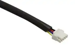
D6T-HARNESS-02
Cable Harness, D6T Series MEMS Thermal Sensors
⚠️ Reference pricing provided. In case of supply shortages, we will connect you with our trusted procurement partners to ensure your project's continuity.
- Manufacturer: OMRON / PARTNER STOCK
- Product type:
- SVHC: To Be Advised
| Delivery and price | |
|---|---|
| Units per pack | 15 |
| Price | 16.75 € |
| Current stock | 100+ |
| Lead time | 30 days |
Datasheet

## **D6T**
## **MEMS Thermal Sensors**
**Contactless measurement with OMRON** \ **D6T Thermal Sensors** : **Able to detect the slightest temperature changes** \
**D6T MEMS Thermal Sensors**
## Contactless Measurement OMRON MEMS Thermal Sensors are able to detect the slightest temperature changes
MEMS Thermal (IR sensor) measures the surface temperature of objects without touching them when the thermopile element absorbs the amount of radiant energy from the object.
2
_**1**_
## Low noise
**World's highest-class stable temperature output***
***According to OMRON's research as of February 2021, except for D6T-32L-01A.**
Easy connection ~~]~~ _**2**_ **Direct temperature value output allows** ~~i~~ **easy software design** ~~**i**~~ i sy i Number of elements and temperature lineup | | _**3**_ **Variation of the number of elements (1 to 1024) x**
Number of elements and temperature lineup **Variation of the number of elements (1 to 1024) x temperature range (-40 to 200°C)**
3
**D6T MEMS Thermal Sensors**
_**1**_
## High Precision
## **World's highest-class stable temperature output***
***According to OMRON's research as of February 2021, except for D6T-32L-01A.**
**Past problem Output was unstable in Stable temperature applications requiring high precision output**
**==> picture [280 x 386] intentionally omitted <==**
**----- Start of picture text -----**<br>
OMRON D6T-1A-01<br>CO<br>28.0<br>27.0 ee<br>Stable output<br>26.0<br>25.024.0 ee<br>23.0 ee<br>ee eee<br>22.0 ee<br>0 5 10 15 20 25 30<br>Time [s]<br>Standard Equivalent Product<br>28.0<br>27.0<br>26.0 Output<br>_ oe fluctuation<br>25.0<br>eeee<br>24.0<br>23.0<br>ee<br>22.0<br>0 5 10 15 20 25 30<br>Time [s]<br>Sensor Output Temperature [°C]<br>Sensor Output Temperature [°C]<br>**----- End of picture text -----**<br>
Note 1. According to OMRON's evaluation method (30-second continuous measurement with a blackbody furnace at 25°C) Note 2. However, product specifications are not guaranteed.
4
**-High Precision- Why?**
## Achieves the world's highest level*[2] of SNR*[1] by combining the in-house designed and manufactured ASIC and MEMS
**==> picture [362 x 51] intentionally omitted <==**
**----- Start of picture text -----**<br>
In-house Pere, In-house =<br>manufactured manufactured<br>ASIC MEMS<br>**----- End of picture text -----**<br>
OMRON designs and manufactures both ASIC and MEMS thermopiles in-house. OMRON's unique digital filter and process optimization reduce the noise of ASIC, achieving the world's highest-level SNR.
*1 SNR: Signal-to-Noise Ratio. Compares the level of a signal to the level of background noise.
*2 According to OMRON's research as of February 2021, except for D6T-32L-01A.
## **Product Structure**
OMRON's unique MEMS technology allows combining thermopile elements and ASICs into one package, resulting in ultra-compact footprint and high precision.
**==> picture [241 x 155] intentionally omitted <==**
**----- Start of picture text -----**<br>
Silicon lens<br>Infrared ray far-infrared focusing<br>» 4<br>MEMS thermopile<br>Electromotive force occurrence<br>ASIC<br>Low noise amplifier<br>MCU<br>A/D conversion,<br>Detect wavelengths in the range 8-12 μm<br>calculation, I2C and I/F<br>**----- End of picture text -----**<br>
## **MEMS thermopile detection principle**
**==> picture [170 x 34] intentionally omitted <==**
**----- Start of picture text -----**<br>
Cold junction Infrared ray (IR) Cold junction<br>Si Hot junction<br>**----- End of picture text -----**<br>
The sensor utilizes the seebeck effect in which thermoelectric force is generated due to the temperature difference that occurs across the junction points of two different types of metal.
5
**D6T MEMS Thermal Sensors**
## Easy connection _**2**_ **Direct temperature value output allows easy software design** »
**==> picture [446 x 451] intentionally omitted <==**
**----- Start of picture text -----**<br>
OMRON D6T CAN packaged thermal sensor from a competitor<br>Temperature<br>o value output<br>Sensor MEMS Sensor MEMS<br>Voltage Voltage<br>A/D conversion A/D conversion<br>Bit value<br>Temperature<br>Bit value<br>conversion<br>Temperature value<br>Customer MCU Customer MCU<br>=<br>Provision of Development Support Tool<br>**----- End of picture text -----**<br>
**==> picture [216 x 79] intentionally omitted <==**
**----- Start of picture text -----**<br>
CAN packaged thermal sensor from a competitor<br>Bit value output<br>**----- End of picture text -----**<br>
MEMS thermal sensors can be connected to **OMRON sensor evaluation boards** .
The below 3 types of platform are applicable. Evaluation can be performed easily by connecting thermal sensor, evaluation board, and harness to the platform.
**Sensor Harness for Connection Evaluation Board** 2JCIE-EV01-RP1 D6T 2JCIE-HARNESS-01 2JCIE-EV01-AR1 2JCIE-EV01-FT1
## **Sample Code**
**Platform**
Raspberry Pi[*1] https://github.com/omron-devhub/d6t-2jcieev01-raspberrypi Arduino[*2] https://github.com/omron-devhub/d6t-2jcieev01-arduino ESP32 Feather[*3] https://github.com/omron-devhub/d6t-2jcieev01-arduino
*1. Raspberry Pi is a registered trademark of the Raspberry Pi Foundation. *2. Arduino is a registered trademark of Arduino LLC and Arduino SRL. *3. Feather is a registered trademark of Adafruit Industries LLC.
6
_**3**_
Number of elements and temperature lineup **Variation of the number of elements (1 to 1024) and the temperature range (-40 to 200°C)**
**==> picture [40 x 409] intentionally omitted <==**
**----- Start of picture text -----**<br>
200<br>80<br>50<br>5<br>0<br>-40<br>Detection Temperature Range [°C]<br>**----- End of picture text -----**<br>
7
**D6T MEMS Thermal Sensors**
## **Example Applications**
The sensors can be used in a wide range of applications, depending on the temperature measurement range.
**==> picture [35 x 11] intentionally omitted <==**
**----- Start of picture text -----**<br>
-40°C<br>**----- End of picture text -----**<br>
**==> picture [309 x 66] intentionally omitted <==**
**----- Start of picture text -----**<br>
Refrigerator Interior & Human Presence<br>Room Temperature Detection Detection<br>Able to detect temperature from Able to detect stationary<br>a long distance human presence<br>**----- End of picture text -----**<br>
**==> picture [155 x 66] intentionally omitted <==**
**----- Start of picture text -----**<br>
Screening of<br>Humans with Fever<br>Contributes to automated<br>non-contact temperature detection<br>**----- End of picture text -----**<br>
**==> picture [32 x 5] intentionally omitted <==**
**----- Start of picture text -----**<br>
36.2°C OK!<br>**----- End of picture text -----**<br>
**==> picture [149 x 18] intentionally omitted <==**
**----- Start of picture text -----**<br>
Home appliances (refrigerators & air conditioners)<br>CO<br>**----- End of picture text -----**<br>
Air conditioners & lighting systems CO)
**==> picture [143 x 18] intentionally omitted <==**
**----- Start of picture text -----**<br>
Room-Entry Management Equipment<br>Co)<br>**----- End of picture text -----**<br>
**==> picture [451 x 156] intentionally omitted <==**
**----- Start of picture text -----**<br>
Recommended Models Recommended Models Recommended Models<br>1×1 1×1 1×1<br>1×8 1×8 1×8<br>°° °<br>4×4 4×4 4×4<br>, ° °<br>32×32 32×32 32×32<br>**----- End of picture text -----**<br>
8
**==> picture [38 x 11] intentionally omitted <==**
**----- Start of picture text -----**<br>
200°C<br>**----- End of picture text -----**<br>
## Comparison with Pyroelectric Sensor
## **Abnormal High Temperature Monitoring** Contributes to prevention of fires due to overheating
Transformers & distribution boards Ct
Both the pyroelectric sensor and non-contact MEMS thermal sensor can detect even the slightest amount of radiant energy from objects such as infrared radiation and convert them into temperature readings. However, unlike pyroelectric sensor that relies on motion detection, non-contact MEMS thermal sensor is able to detect the presence of stationary humans (or objects).
## a **Pyroelectric sensor**
Converts temperature readings only when detecting “temperature changes in the radiant energy” in its field of view.
**==> picture [294 x 237] intentionally omitted <==**
**----- Start of picture text -----**<br>
Output signal<br>Detected Detected<br>a Undetected<br>|; /\- -<br>| :<br>}<br>Able to detect human Unable to detect stationary Able to detect human<br>(object) motion human (object) presence (object) motion<br>[Td MEMS thermal sensor (thermopile)<br>Converts temperature readings by “continuously detecting the temperature<br>of radiant energy” in its field of view<br>**----- End of picture text -----**<br>
## [Td **MEMS thermal sensor (thermopile)**
## **Recommended Models**
**==> picture [30 x 120] intentionally omitted <==**
**----- Start of picture text -----**<br>
1×1<br>1×8<br>4×4<br>32×32<br>**----- End of picture text -----**<br>
**==> picture [283 x 175] intentionally omitted <==**
**----- Start of picture text -----**<br>
Output signal Detected Detected Detected<br>Lf TT<br>. Bi<br>a "- IN 2 _| : oe m ; a<br>~* EE 7 a ye ft é<br>) ome :<br>. } :<br>Able to detect both stationary and motion<br>state of humans (objects).<br>**----- End of picture text -----**<br>
9
**D6T MEMS Thermal Sensors**
## **Viewing Angle and Measurement Area**
Choose your preferred sensor viewing angle to meet your application needs.
|**Model**<br>~~Pe~~|**D6T-1A-01 **<br>~~Pe~~|**D6T-1A-02**<br>~~Pe~~|**D6T-8L-09**<br>~~Pe~~|**D6T-8L-09H **<br>~~Pe~~|**D6T-44L-06**<br>~~Pe~~|**D6T-44L-06H**<br>~~Pe~~|**D6T-32L-01A**<br>~~Pe~~|
|---|---|---|---|---|---|---|---|
|**Appearance**|e||@|||||
|**Number of**<br>**elements**|**1(1x1)**||**8 (1x 8)**||**16 (4x4)**||**10 2 4 (3 2 x 3 2)**|
|**Viewing angle**<br>**X-direction**<br>**Y-direction**|**X = 58.0°**<br>**Y = 58.0°**|**X = 26.5°**<br>**Y = 26.5°**|**X = 54.5°**<br>**Y = 5.5°**||**X=44.2°**<br>**Y=45.7°**||**X=90.0°**<br>**Y=90.0°**|
|**Size of**<br>**measurement**<br>**area**|**X**<br>**Y**<br>**Distance**||**X**<br>**Y**<br>**Distance**||**X**<br>**Y**<br>**Distance**||**X**<br>**Y**<br>**Distance**|
|**Distance**<br>**10 cm**|**X = 11 cm**<br>**Y = 11 cm**|**X = 4.7 cm**<br>**Y = 4.7 cm**|**X = 10 cm**<br>**Y = 1.0 cm**||**X = 8.1 cm**<br>**Y = 8.4 cm**||**X = 20 cm**<br>**Y = 20 cm**|
|**Distance**<br>**50 cm**|**X = 55 cm**<br>**Y = 55 cm**|**X = 24 cm**<br>**Y = 24 cm**|**X = 52 cm**<br>**Y = 4.8 cm**||**X = 41 cm**<br>**Y = 42 cm**||**X = 100 cm**<br>**Y = 100 cm**|
|**Distance**<br>**1 m**|**X = 111 cm**<br>**Y = 111 cm**|**X = 47 cm**<br>**Y = 47 cm**|**X = 103 cm**<br>**Y = 10 cm**||**X = 81 cm**<br>**Y = 84 cm**||**X = 200 cm**<br>**Y = 200 cm**|
|**Distance**<br>**2 m**|**X = 222 cm**<br>**Y = 222 cm**|**X = 94 cm**<br>**Y = 94 cm**|**X = 206 cm**<br>**Y = 20 cm**||**X = 162 cm**<br>**Y = 169 cm**||**X = 400 cm**<br>**Y = 400 cm**|
|**Distance**<br>**3 m**|**X = 333 cm**<br>**Y = 333 cm**|**X = 141 cm**<br>**Y = 141 cm**|**X = 309 cm**<br>**Y = 30 cm**||**X = 244 cm**<br>**Y = 253 cm**||**X = 600 cm**<br>**Y = 600 cm**|
- *. The sizes of measurement areas indicated above are for reference only.
- *. The size of the measurement area changes according to sensor mounting angle
10
D6T **MEMS Thermal Sensors**
## **MEMS Non-Contact Thermal Sensor for Contactless Measurement**
- **Achieves the world's highest level[*2] of SNR[*1] by combining the inhouse designed and manufactured ASIC and MEMS**
- **Direct temperature value output allows easy software design**
- **Variation of the number of elements (1 to 1024) and the temperature range (-40 to 200°C)**
*1. SNR: Signal-to-Noise Ratio. Compares the level of a signal to the level of background noise.
*2. According to OMRON's research as of February 2021, except for D6T-32L-01A.
## **RoHS Compliant** ~~[~~
Refer to _Safety Precautions_ on page 18.
## **Ordering Information**
## **Thermal Sensors**
**==> picture [203 x 249] intentionally omitted <==**
**----- Start of picture text -----**<br>
a Element type Model Shape<br>D6T-1A-01<br>1 1<br>D6T-1A-02<br>D6T-8L-09<br>1 8 _ ©<br>D6T-8L-09H<br>D6T-44L-06<br>4 4<br>eh D6T-44L-06H<br>—_<br>©}<br>32 32 D6T-32L-01A<br>**----- End of picture text -----**<br>
## **Model Number Legend**
## D6T-@-@ @
(1) (2) (3)
## **(1) Number of elements**
- 1A : 1 (1 × 1)
- 8L : 8 (1 × 8)
44L : 16 (4 × 4)
32L : 1024 (32 × 32)
## **(2) Viewing angle**
- 01 : X direction, Y direction=58.0
- 02 : X direction, Y direction=26.5
- 09 : X direction=54.5 , Y direction=5.5
- 06 : X direction=44.2 , Y direction=45.7
01A : X direction, Y direction=90
## **(3) Special Functions**
H : High-temperature type Non-display : Standard sensor
## **Accessories (Sold separately)**
|Type|Model|
|---|---|
|Cable Harness|**D6T-HARNESS-02**|
## **Others**
MEMS thermal sensors can be connected to OMRON sensor evaluation boards.
The below 3 types of platform are applicable. Evaluation can be performed easily by connecting thermal sensor, evaluation board, and harness to the platform.
|Platform|Evaluation Board<br>Harness for connection (Evaluation Board - D6T)|Harness for connection (Evaluation Board - D6T)|Sample Source Code|
|---|---|---|---|
|For Raspberry Pi*1|2JCIE-EV01-RP1|2JCIE-HARNESS-01|https://github.com/omron-devhub/d6t-2jcieev01-raspberrypi|
|For Arduino*2|2JCIE-EV01-AR1|2JCIE-HARNESS-01|https://github.com/omron-devhub/d6t-2jcieev01-arduino|
|For ESP32 Feather*3|2JCIE-EV01-FT1|2JCIE-HARNESS-01|https://github.com/omron-devhub/d6t-2jcieev01-arduino|
For details of evaluation boards and sample source codes, refer to the following website. (https://components.omron.com/sensor/evaluation-board/2jcie)
*1. Raspberry Pi is a registered trademark of the Raspberry Pi Foundation.
*2. Arduino is a registered trademark of Arduino LLC and Arduino SRL.
- *3. Feather is a registered trademark of Adafruit Industries LLC.
**11**
**MEMS Thermal Sensors**
## **D6T**
## **Ratings, Specifications, and Functions**
## **Ratings**
|Item<br>Model|**D6T-1A-01**|**D6T-1A-02**|**D6T-8L-09**|**D6T-8L-09H**|**D6T-44L-06**|**D6T-44L-06H**|**D6T-32L-01A**|
|---|---|---|---|---|---|---|---|
|Power supply voltage|4.5 to 5.5 VDC|||||||
|Storage temperature range|-20 to 80C<br>-40 to 80C<br>-20 to 80C<br>-10 to 60C<br>-20 to 80C<br>(with no icing or condensation)|||||||
|Operating temperature range|0 to 60C<br>-40 to 80C<br>0 to 60C<br>0 to 50C<br>-10 to 70C<br>(with no icing or condensation)|||||||
|Storage humidity range|95% max.<br>95% max.<br>95% max.<br>85% max.<br>95% max.<br>(with no icing or condensation)|||||||
|Operating humidity range|20% to 95%<br>20% to 95%<br>20% to 95%<br>20% to 85%<br>20% to 95%<br>(with no icing or condensation)|||||||
## **Characteristics**
|Item|Model|**D6T-1A-01**|**D6T-1A-02**|**D6T-8L-09**|**D6T-8L-09H**|**D6T-44L-06**|**D6T-44L-06H**|**D6T-32L-01A**|
|---|---|---|---|---|---|---|---|---|
|View angle*1|X direction|58.0|26.5|54.5||44.2||90|
||Y direction|58.0|26.5|5.5||45.7||90|
|Object temperature<br>output accuracy*2|Accuracy 1|1.5C max.<br>Measurement conditions: Vcc = 5.0 V<br>(1) Tx = 25C, Ta = 25C<br>(2) Tx = 45C, Ta = 25C<br>(3) Tx = 45C, Ta = 45C||||||Within ±3.0C<br>Measurement<br>conditions:<br>Vcc = 5.0 V<br>Tx = 25C,<br>Ta = 25C<br>Central 16x16-<br>pixel area|
|Current consumption||3.5 mA typical||5 mA typical||||19 mA typical|
## **Functions**
|Item|Model|**D6T-1A-01**|**D6T-1A-02**|**D6T-8L-09**|**D6T-8L-09H**|**D6T-44L-06**|**D6T-44L-06H**|**D6T-32L-01A**|
|---|---|---|---|---|---|---|---|---|
|Object temperature detection<br>range*2||5 to 50C|-40 to 80C|5 to 50C|5 to 200C|5 to 50C|5 to 200C|0 to 200C|
|Ambient temperature detection<br>range*2||5 to 45C|-40 to 80C|5 to 45C|5 to 45C|5 to 45C|5 to 45C|0 to 80C|
|Output specifications||Digital values that correspond to the object temperature (Tx) and reference temperature<br>(Ta) are output from a serial communications port.|||||||
|Output form<br>(Object temperature detection)||Binary code (10 times the detected temperature (C))|||Binary code<br>(5 times the<br>detected<br>temperature<br>(C))|Binary code (10 times the detected temperature (C))|||
|Output form<br>(Reference temperature inside the<br>sensor)||Binary code (10 times the detected temperature (C))|||||||
|Communications form||I2C compliant|||||||
|Temperature resolution (NETD)*3||0.02C<br>(Data update<br>cycle 100 msec)|0.06C<br>(Data update<br>cycle 100 msec)|0.03C<br>(Data update<br>cycle 250 msec)|0.03C<br>(Data update<br>cycle 250 msec)|0.06C<br>(Data update<br>cycle 300 msec)|0.06C<br>(Data update<br>cycle 300 msec)|0.33C*4<br>(Data update<br>cycle 200 msec)|
*1. Refer to _Field of View Characteristics_ .
*2. Refer to _Object Temperature Detection Range_ .
*3. Reference data
*4. Taken to be the average value of the central 4 pixels.
**12**
D6T
**MEMS Thermal Sensors**
## **Object Temperature Detection Range**
D6T-44L-06, D6T-8L-09, D6T-1A-01
**==> picture [240 x 160] intentionally omitted <==**
**----- Start of picture text -----**<br>
55<br>50<br>45<br>40<br>35<br>30<br>25<br>20<br>15<br>10<br>5<br>0 : Object temperature<br>-5 detection range<br>-5 0 5 10 15 20 25 30 35 40 45 50 55<br>Object temperature Tx (°C)<br>Reference temperature Ta (°C)<br>**----- End of picture text -----**<br>
D6T-44L-06H, D6T-8L-09H
**==> picture [228 x 171] intentionally omitted <==**
**----- Start of picture text -----**<br>
: Object temperature detection range<br>50<br>45<br>40<br>35<br>30<br>25<br>20<br>15<br>10<br>5<br>0<br>-10 0 20 40 60 80 100 120 140 160 180 200<br>Object temperature Tx (°C)<br>Reference temperature Ta (°C)<br>**----- End of picture text -----**<br>
D6T-1A-02
**==> picture [240 x 160] intentionally omitted <==**
**----- Start of picture text -----**<br>
90<br>80<br>70<br>60<br>50<br>40<br>30<br>20<br>10<br>0<br>-10<br>-20<br>-30<br>-40 : Object temperature<br>-50 detection range<br>-50 -40 -30 -20 -10 0 10 20 30 40 50 60 70 80 90<br>Object temperature Tx (°C)<br>Reference temperature Ta (°C)<br>**----- End of picture text -----**<br>
D6T-32L-01A
**==> picture [229 x 171] intentionally omitted <==**
**----- Start of picture text -----**<br>
: Object temperature detection range<br>90<br>80<br>70<br>60<br>50<br>40<br>30<br>20<br>10<br>0<br>-10<br>-10 0 20 40 60 80 100 120 140 160 180 200<br>Object temperature Tx (°C)<br>Reference temperature Ta (°C)<br>**----- End of picture text -----**<br>
## **Connections**
## **Thermal Sensor Configuration Diagram**
<D6T-8L-09>
## <D6T-8L-09H>
**==> picture [217 x 68] intentionally omitted <==**
**----- Start of picture text -----**<br>
Sensor element Amplifier Digital processor<br>Pixel 0<br>4. SCL<br>3. SDA<br>2. VCC<br>1. GND<br>Pixel 7<br>**----- End of picture text -----**<br>
## **Terminal Arrangement**
|Terminal|Name|Function|Remarks|
|---|---|---|---|
|1|GND|Ground||
|2|VCC|Positive power supply<br>voltage input||
|3|SDA|Serial data I/O line|Connect the open-drain SDA<br>terminal to a pull-up resistor.|
|4|SCL|Serial clock input|Connect the open-drain SCL<br>terminal to a pull-up resistor.|
Note: The D6T-44L-06 has pixels 0 to 15. The D6T-44L-06H has pixels 0 to 15. The D6T-1A-01 has pixel 0. The D6T-1A-02 has pixel 0. The D6T-32L-01A has pixel 0 to 1023.
**13**
**D6T**
**MEMS Thermal Sensors**
## **Field of View Characteristics**
## **D6T-44L-06**
## **D6T-44L-06H**
## **Field of View in Y Direction**
## **Detection Area for Each Pixel**
**Field of View in X Direction**
**==> picture [242 x 142] intentionally omitted <==**
**----- Start of picture text -----**<br>
Y View angle<br>X View angle<br>45.7°<br>44.2°<br>poe<br>——=< — so 2 7<br>Note: Definition of view angle: Using the maximum sensor output as a a1cPi<br>reference, the angular range where the Sensor output is 50% or higher<br>when the angle of the Sensor is changed is defined as the View angle.<br>**----- End of picture text -----**<br>
**D6T-8L-09 D6T-8L-09H Field of View in X Direction**
## **Field of View in Y Direction**
**==> picture [185 x 15] intentionally omitted <==**
**----- Start of picture text -----**<br>
X View angle Y View angle<br>54.5° 5.5°<br>**----- End of picture text -----**<br>
Note: Definition of view angle: Using the maximum Sensor output as a reference, the angular range where the Sensor output is 50% or higher when the angle of the Sensor is changed is defined as the view angle.
**==> picture [130 x 123] intentionally omitted <==**
**----- Start of picture text -----**<br>
−<br>Y direction<br>P0<br>P1<br>+<br>P4 P2<br>P3 +<br>P5<br>P8 P6<br>P7<br>P9 _<br>7<br>P12 a P10 a P11 X direction<br>P13<br>P14<br>P15<br>_ −<br>**----- End of picture text -----**<br>
## **Detection Area for Each Pixel**
**==> picture [86 x 166] intentionally omitted <==**
**----- Start of picture text -----**<br>
− Y direction<br>+<br>, , , P0 +<br>P1<br>y<br>¢ , P2<br>P3<br>X direction<br>P4<br>P5<br>\<br>| \ P6<br>\<br>\ \ ‘PS P7<br>. | −<br>**----- End of picture text -----**<br>
**14**
D6T
**MEMS Thermal Sensors**
## **D6T-1A-01**
## **Field of View in X Direction**
X View angle 58.0° ~~Z~~ **D6T-1A-02**
## **Field of View in X Direction**
**==> picture [41 x 15] intentionally omitted <==**
**----- Start of picture text -----**<br>
X View angle<br>26.5°<br>**----- End of picture text -----**<br>
## **Field of View in Y Direction**
**==> picture [42 x 15] intentionally omitted <==**
**----- Start of picture text -----**<br>
Y View angle<br>58.0°<br>**----- End of picture text -----**<br>
## **Field of View in Y Direction**
**==> picture [42 x 14] intentionally omitted <==**
**----- Start of picture text -----**<br>
Y View angle<br>26.5°<br>**----- End of picture text -----**<br>
## **Detection Area for Each Pixel**
**==> picture [68 x 39] intentionally omitted <==**
**----- Start of picture text -----**<br>
X direction<br>Y direction<br>**----- End of picture text -----**<br>
Note: Definition of view angle: Using the maximum Sensor output as a reference, the angular range where the Sensor output is 50% or higher when the angle of the Sensor is changed is defined as the view angle.
## **D6T-32L-01A Field of View in X Direction**
## **Field of View in Y Direction**
## **Detection Area for Each Pixel**
X View angle 90.0°
**==> picture [499 x 150] intentionally omitted <==**
**----- Start of picture text -----**<br>
Y View angle -<br>90.0° 90.0° P0 Y direction<br>P1<br>P32 P33 P2 P3 +<br>P64 P30<br>P31 +<br>P992 X direction<br>P1023<br>se kh<br>Note: Definition of view angle: Using the maximum Sensor output as a refer- -<br>ence, the angular range where the Sensor output is 50% or higher when<br>the angle of the Sensor is changed is defined as the view angle.<br>…<br>…<br>…<br>…<br>**----- End of picture text -----**<br>
**15**
**D6T**
**MEMS Thermal Sensors**
## **Dimensions** ~~mm~~ **CAD Data Please visit our CAD Data website, which is noted on the last page.** (Unit: mm) **D6T-44L-06** GD CAD Data **D6T-44L-06H**
**==> picture [418 x 339] intentionally omitted <==**
**----- Start of picture text -----**<br>
GD CAD Data<br>Supporting and Mounting Area (Shaded Portion)<br>Top View<br>1<br>R1<br>18<br>5 11.5 Two, 1 dia.<br>1.5<br>11 14<br>R1<br>3.4 1<br>8 a .3 di a. __ Bottom View<br>(3.75)<br>1<br>R1<br>1 4.4<br>r e i 4 y=tle (TIL IL ELIOT RF 2.5<br>( 0.85) 7 o )<br>4.05 SCL GND 1 2 Z\__¥<br>SDA VCC ]<br>5 SM04B-GHS-TB(JST) J<br>8.25<br>ol Ld i<br>4] oe 2.5<br>R1<br>1<br>Note: Due to insulation distance limitations, do<br>not allow metal parts to come into contact<br>with the Sensor.<br>**----- End of picture text -----**<br>
**==> picture [393 x 320] intentionally omitted <==**
**----- Start of picture text -----**<br>
CAD Data<br>Supporting and Mounting Area (Shaded Portion)<br>Top View —_<br>2 max.<br>12 0.8 max.<br>2 max.<br>5<br>| pera,<br>11.6<br>cs 6<br>2 max.<br>0.8 max. LZZZZZZZZ LLL LLL LLLLLL<br>© Is<br>8.3 dia. 2 max.<br>5.32<br>Bottom View<br>1 4.4<br>SCL GND<br>4.05 (0.78) SDA VCC 1 max.<br>SM04B-GHS-TB(JST)<br>ia<br>7 Oe<br>8.25<br>1 max.<br>é_, | | Y to<br>1 max.<br>**----- End of picture text -----**<br>
**D6T-8L-09 D6T-8L-09H**
Note: Due to insulation distance limitations, do not allow metal parts to come into contact with the Sensor.
Note: Unless otherwise specified, a tolerance of 0.3 mm applies to all dimensions.
**16**
D6T
**MEMS Thermal Sensors**
## **D6T-1A-01 D6T-1A-02**
**==> picture [397 x 315] intentionally omitted <==**
**----- Start of picture text -----**<br>
Supporting and Mounting Area Ga» CAD Data<br>(Shaded Portion)<br>Top View 2 max.<br>12±0.2 0.8 max.<br>2 max.<br>5<br>11.6±0.2<br>N OY ) O HO<br>2 max.<br>0.8 max. WELL<br>2 max.<br>8.3 dia.<br>(3.79)<br>Bottom View<br>1 4.4<br>SCL GND<br>1 max.<br>7 4.05 a 0.78 i SDA VCC I)<br>SM04B-GHS-TB(JST)<br>ie BE<br>Y oo<br>8.25<br>cq || | i<br>1 max.<br>1 max.<br>Note: Due to insulation distance limitations, do not allow<br>metal parts to come into contact with the Sensor.<br>**----- End of picture text -----**<br>
**==> picture [525 x 282] intentionally omitted <==**
**----- Start of picture text -----**<br>
BO D6T-32L-01A Supporting and Mounting Area CAD Data<br>18 (Shaded Portion) 1<br>5 4-1.3 dia. 1 Top View<br>14.8 4-R1.5<br>- ooo 3.2 ZZ 000<br>WA & S7's s'| 10.7 | 14 | SSS)<br>\ » oy 3.2 TE Vi<br>1 3.1 3.1<br>8.15 dia .<br>4.53 1 Bottom View<br>R1.2<br>Max3.5 1 4.4 1<br>2.9<br>s s 7 ae | 4.05 (0.85) SCL GND \ ©® | =p<br>SDA VCC \eo =<br>SM04B-GHS-TBLFSN(JST)<br>O mo 000 _O \ 90 | tl<br>2.9<br>1<br>Oo os 8.25 :<br>2.8 2.8<br>eo LI Note: Due to insulation distance limitations, do not allow<br>0 000 69 metal parts to come into contact with the Sensor.<br>D6T<br>**----- End of picture text -----**<br>
**==> picture [512 x 19] intentionally omitted <==**
**----- Start of picture text -----**<br>
Cable :UL1061.AWG#28<br>a D6T-HARNESS-02 (Optional - sold separately) CAD Data<br>**----- End of picture text -----**<br>
Cable :UL1061.AWG#28 **D6T-HARNESS-02 (Optional - sold separately)** CAD Data UL Tube : T-105-2 No.8 Connector : GHR-04V-S GND **Cable Color** Contact : SSHL-002T-P0.2 GND ¡ BLACK Wire VCC VCC ¡ RED Wire SDA ¡ BLUE Wire SDA SCL ¡ YELLOW Wire 5 ~~660±10~~ SCL ~~=~~ ***** Length of Cable ~~15±3~~ ***** (ϕ3.38 PVC·Black) ~~730±10~~ removed sheath. ~~750±10~~
Note: Unless otherwise specified, a tolerance of 0.3 mm applies to all dimensions.
**17**
**D6T**
**MEMS Thermal Sensors**
## **Safety Precautions**
## **Precautions for Correct Use**
## ● **Installation**
- The sensor may not achieve the characteristics given in this datasheet due to the ambient environment or installation location. Before using the Sensor, please acquire an adequate understanding and make a prior assessment of Sensor characteristics in your actual system.
## ● **Operating Environment**
- Do not use the Sensor in locations where dust, dirt, oil, and other foreign matter will adhere to the lens. This may prevent correct temperature measurements.
- Do not use the Sensor in any of the following locations.
- Locations where the Sensor may come into contact with water or oil
- Outdoors
- Locations subject to direct sunlight.
- Locations subject to corrosive gases (in particular, chloride, sulfide, or ammonia gases).
- Locations subject to extreme temperature changes
- Locations subject to icing or condensation.
- Locations subject to excessive vibration or shock.
## ● **Noise Countermeasures**
- The Sensor does not contain any protective circuits. Never subject it to an electrical load that exceeds the absolute maximum ratings for even an instance. The circuits may be damaged. Install protective circuits as required so that the absolute maximum ratings are not exceeded.
- Keep as much space as possible between the Sensor and devices that generates high frequencies (such as high-frequency welders and high-frequency sewing machines) or surges.
## ● **Handling**
- This Sensor is a precision device. Do not drop it or subject it to excessive shock or force. Doing so may damage the Sensor or change its characteristics. Never subject the connector to unnecessary force. Do not use a Sensor that has been dropped.
- Take countermeasures against static electricity before you handle the Sensor.
- Turn OFF the power supply to the system before you install the Sensor. Working with the Sensor while the power supply is turned ON may cause malfunctions.
- Secure the Sensor firmly so that the optical axis does not move.
- Install the Sensor on a flat surface. If the installation surface is not even, the Sensor may be deformed, preventing correct measurements.
- Do not install the Sensor with screws. Screws may cause the resist to peel from the board. Secure the Sensor in a way that will not cause the resist to peel.
- Always check operation after you install the Sensor.
- Use the specified connector (GHR-04 from JST) and connect it securely so that it will not come off. If you solder directly to the connector terminals, the Sensor may be damaged.
- Make sure to wire the polarity of the terminals correctly. Incorrect polarity may damage the Sensor.
- Never attempt to disassemble the Sensor.
- Do not use the cable harness to the other product.
- Attach a surge protector or noise filter on nearby noise-generating devices (in particular, motors, transformers, solenoids, magnetic coils, or devices that have an inductance component).
- In order to prevent inductive noise, separate the connector of the Sensor from power lines carrying high voltages or large currents. Using a shielded line is also effective.
- If a switching requlator is used, check that malfunctions will not occur due to switching noise from the power supply.
**18**
MEMO
**==> picture [512 x 767] intentionally omitted <==**
**19**
## **Information of Related Products**
**==> picture [491 x 228] intentionally omitted <==**
**----- Start of picture text -----**<br>
omron D6T Sensor Evaluation Board2JCIE-EV 2JCIE-EV<br>MEMS Thermal SensorsD6T MEMS Thermal Sensor Sensor evaluation board that supports open platform • Easily implement development of a new IoT system that senses a wide variety of environmental information Sensor Evaluation Board<br>User's Manual RoHS compliant _ Refer to Safety Precautions on Page 9. &<br>User’s Manual Features Easily develop sensing IoT applications and PoC • Evaluation board with six types of sensing functions.• The product can be connected to a Raspberry Pi *1, Arduino *2, or Feather *3 baseboard, and enables easy sensor • The product can be connected to OMRON sensors (MEMS thermal sensor, MEMS flow sensor, Light convergent evaluation.reflective sensor, air quality sensor, etc.) and Qwiic sensors.<br>OMRON sensor evaluation board Can be connected to OMRON sensors * 4<br>MEMS Thermal Sensors Six types of sensing functions Temperature, humidity, light, barometric pressure, noise, acceleration Platform + Includes a connector that supports Qwiic sensors. Can be connected to a variety of sensors<br>a> Catalog No. *1.*2.*3.*4. Raspberry Pi is a registered trademark of the Raspberry Pi Foundation. Arduino is a registered trademark of Arduino LLC and Arduino SRL. Feather is a registered trademark of Adafruit Industries LLC. For details, see External Expansion Sensor on page 3. Sam ee ple source code for ac = (Raspberry Pi) quiring + sensor data is available on GitHub Raspberry Pi *1, Arduino *2, Feather *3 Supports three platforms Catalog No.<br>A284-E1 1 A297-E1<br>D6F series MEMS Flow Sensors omRon D6F omron Sensor Selection Guide<br>~~ Faster and more accurate than ever beforeMEMS flow sensor : the ideal means for mass flow measurementSeries Catalog —_ MEMS Flow Sensor SensorSelection Guide ; Sensor Selection Guide<br>OMRON's unique sensing technology responds to evolving needs.<br>Omron flow sensorso preciseeven the flap of a butterfly’s<br>wings will not be missed. © (2)<br>pa _4 is S43<br>Catalog No. Catalog No.<br>X211-E1 Photomicro Sensor Limited Reflective Sensor Sensor Module3D TOF MEMS Flow Sensor Environment Sensor MEMS Non-Contact Thermal Sensor Seismic Sensor Pressure SensorMEMS Gauge Human Vision Components Y232-E1<br>**----- End of picture text -----**<br>
Please check each region's Terms & Conditions by region website.
## **OMRON Corporation Electronic and Mechanical Components Company**
## **Regional Contact**
**Americas Europe** https://components.omron.com/ http://components.omron.eu/ **Asia-Pacific China** https://ecb.omron.com.sg/ https://www.ecb.omron.com.cn/ **Korea Japan** https://www.omron-ecb.co.kr/ https://www.omron.co.jp/ecb/
© OMRON Corporation 2018-2021 All Rights Reserved.
**Cat. No. A274-E1-05**
In the interest of product improvement, specifications are subject to change without notice.
0321(0618)
Updated at June 9, 2026
About Novapart
Novapart is a B2B electronic component broker specialising in stock shortages and cost reduction. We source hard-to-find parts and identify compliant alternatives across a catalogue of 410,000+ components from 500+ manufacturers.
Learn more →Stock Shortage Specialist
When a component is unavailable, discontinued or has an unacceptable lead time, we tap into our network of vetted European and Asian distributors to source what you need — without compromising on quality or traceability.
Request a quote →Compliant Alternatives
We identify pin-to-pin, electrically equivalent substitutes that meet the same certifications (RoHS, AEC-Q100, REACH) as your original specification — validated against datasheets, not just part numbers. Often at a lower cost.
BOM Analysis service →