


D4A0001N
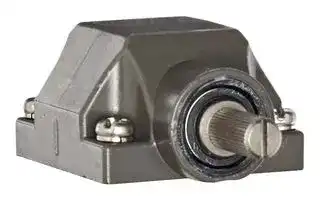
HEAD, STANDARD SIDE, ROLLER LEVER SWITCH
- Manufacturer: OMRON INDUSTRIAL AUTOMATION
- Product type: Industrial Switch Accessories
- Accessory Type:Head; For Use With:Omron D4A Series Roller Lever Switches; Product Range:D4A Series 37B9840
- For Use With: Omron D4A Series Roller Lever Switches
- Product Range: D4A Series
- Accessory Type: Head
| Delivery and price | |
|---|---|
| Units per pack | 1 |
| Price | 76.78 € |
| Current stock | 10+ |
| Lead time | 30 days |
**General-purpose Limit Switch D4A-** @ **N**

CSM_D4A-_N_DS_E_3_1

## **The Limit Switch with Better Seal, Shock Resistance, and Strength**

- A double seal on the head, a complete gasket cover, and other features ensure a better seal (meets UL NEMA 3, 4, 4X, 6P, 12, 13).

- Wide standard operating temperature range:

- −40°C to +100°C (standard type).

- Models with fluoro-rubber available for greater resistance to chemicals.

- Block mounting method also reduces downtime for maintenance.

- DPDT, double-break models available for complex operations.

- Approved by UL, CSA, and CCC (Chinese standard).

(Ask your OMRON representative for information on approved model.)

Be sure to read _Safety Precautions_ on page 14 to 15 and _Safety Precautions for All Limit Switches_ .

## **Model Number Structure**

**Model Number Legend** (Not all combinations are possible. Ask your OMRON representative for details.)

## **D4A-** @@@@ **N (Set model number)**

## **(1) (2) (3)**

## **(1) Receptacle box**

- 1 : 1/2-14 NPT conduit (SPDT, double-break)

- 2 : 1/2-14 NPT conduit (DPDT, double-break)

- 3 : G 1/2 conduit (SPDT, double-break)

- 4 : G 1/2 conduit (DPDT, double-break)

## **(2) Switch Box**

- 1 : SPDT, double-break, without indicator

- 3 : SPDT, double-break, neon lamp

- E : SPDT, double-break, LED (24 VDC, leakage current: 1.3 mA)

- 5 : DPDT, double-break, simultaneous operation, without indicator

- 7 : DPDT, double-break, sequential operation, without indicator *1

- 9 : DPDT, double-break, center neutral operation, without indicator *2

- L : DPDT, double-break, simultaneous operation, neon lamp

- P : DPDT, double-break, simultaneous operation, LED

## **(3) Head**

   - 01 : Roller lever, standard

   - 02 : Roller lever, high-sensitivity 03 : Roller lever, low torque 04 : Roller lever, high-sensitivity, low torque 05 : Roller lever, maintained 17 : Roller lever, sequential operation 18 : Roller lever, center neutral operation 06 : Side plunger, standard

   - 07-V : Side plunger, vertical roller 07-H : Side plunger, horizontal roller 08 : Side plunger, adjustable 09 : Top plunger, standard 10 : Top plunger, roller 11 : Top plunger, adjustable 12 : Flexible rod, spring wire 14 : Flexible rod, plastic rod 15 : Flexible rod, cat whisker 16 : Flexible rod, coil spring

- *1. Use the D4A-0017N Special Head.

- *2. Use the D4A-0018N Special Head.

Note: Fluoro-rubber sealed type is also available.

**1**

**D4A-** @ **N**

## **Ordering Information**

## **Set model number**

## **SPDT, Double-break Switches**

||**Receptacle box**|**Receptacle box**|**G 1/2 Conduit**|**G 1/2 Conduit**|**G 1/2 Conduit**|**G 1/2 Conduit**|**G 1/2 Conduit**|
|---|---|---|---|---|---|---|---|
||**Indicator**||**Without indicator**||**With neon lamp indicator (AC)**||**With LED indicator (DC)**|
||||**Model**|**Approved**<br>**standards**|**Model**|**Approved**<br>**standards**|**Model**|
|**Actuator**||||||||
|**Roller lever *1**|**Standard**||**D4A-3101N**|UL, CSA|**D4A-3301N**|UL, CSA|**D4A-3E01N**|
||**High-sensitivity**||**D4A-3102N**|UL, CSA|**D4A-3302N**|UL, CSA|**D4A-3E02N**|
||**Low-torque**||**D4A-3103N**|UL, CSA|---|---|---|
||**High-sensitivity,**<br>**Low-torque**||**D4A-3104N**|UL, CSA|**D4A-3304N**|UL, CSA|---|
||**Maintained *2**||**D4A-3105N**|UL, CSA|**D4A-3305N**|UL, CSA|**D4A-3E05N**|
|**Side plunger**|**Standard**||**D4A-3106N**|UL, CSA|---|---|---|
||**Vertical roller**||**D4A-3107-VN**|UL, CSA|**D4A-3307-VN**|UL, CSA|**D4A-3E07-VN**|
||**Horizontal roller**||**D4A-3107-HN**|UL, CSA|**D4A-3307-HN**|UL, CSA|---|
||**Adjustable**||**D4A-3108N**|UL, CSA|**D4A-3308N**|UL, CSA|**D4A-3E08N**|
|**Top plunger**|**Standard**||**D4A-3109N**|UL, CSA|**D4A-3309N**|UL, CSA|---|
||**Roller**||**D4A-3110N**|UL, CSA|**D4A-3310N**|UL, CSA|---|
||**Adjustable**||**D4A-3111N**|UL, CSA|**D4A-3311N**|UL, CSA|---|
|**Flexible rod**|**Spring wire**||**D4A-3112N**|UL, CSA|**D4A-3312N**|UL, CSA|**D4A-3E12N**|
||**Plastic rod**||**D4A-3114N**|UL, CSA|**D4A-3314N**|UL, CSA|**D4A-3E14N**|
||**Cat whisker**||**D4A-3115N**|UL, CSA|**D4A-3315N**|UL, CSA|**D4A-3E15N**|
||**Coil spring**||**D4A-3116N**|UL, CSA|**D4A-3316N**|UL, CSA|**D4A-3E16N**|


Note: 1. Switches are also available with @1/2-14 NPT conduits. The model numbers correspond as follows: (Examples) G 1/2 Conduits 1/2-14 NPT Conduits

- D4A-3@@@N D4A-1@@@N

D4A-4@@@N D4A-2@@@N

2. Switches are also available with fluoro-rubber seals for higher resistance to chemicals. (The operating temperature range for these Switches, however, is −10 to +120°C.) Add “-F” to the model number. (Example: D4A-3101N becomes D4A-3101N-F.) Ask your nearest OMRON representative for details.

- *1. The lever is not included with the Roller Level Models. Select the lever from those listed in this data sheet and order it separately (refer to Levers on page 12).

- *2. The Maintained Switches have a lock mechanism for the switch operation and thus use a Fork Lever Lock.

**2**

**D4A-** @ **N**

## **DPDT, Double-break Switches**

|**Receptacle box**<br>**Indicator**<br>**Actuator**<br>~~[_~~|**Receptacle box**<br>**Indicator**<br>**Actuator**<br>~~[_~~|**Receptacle box**<br>**Indicator**<br>**Actuator**<br>~~[_~~|**G 1/2 Conduit**<br>~~[_~~|**G 1/2 Conduit**<br>~~[_~~|**G 1/2 Conduit**<br>~~[_~~|**G 1/2 Conduit**<br>~~[_~~|
|---|---|---|---|---|---|---|
||||**Without indicator**<br>~~[_~~||**With neon lamp indicator (AC)**|**With LED indicator (DC)**|
||||**Model**<br>~~[_~~|**Approved standards**<br>~~|~~|**Model**|**Model**|
|**Roller lever *1**|**Standard**<br>~~[_~~||**D4A-4501N**<br>~~[_~~|UL, CSA<br>~~|~~|**D4A-4L01N**|**D4A-4P01N**|
||**High-sensitivity**<br>~~—~~||**D4A-4502N**|UL, CSA|---|---|
||**Low-torque**<br>~~—~~||**D4A-4503N**|UL, CSA|---|---|
||**High-sensitivity,**<br>**Low-torque**<br>~~—~~<br>~~—~~||**D4A-4504N**|UL, CSA|---|---|
||**Maintained*2**<br>~~—~~||**D4A-4505N**|UL, CSA|---|---|
||**Sequential operation**||**D4A-4717N**|UL, CSA|---|---|
||**Center neutral**<br>**operation**||**D4A-4918N**|UL, CSA|---|---|
|**Side plunger**|**Standard**||**D4A-4506N**|UL, CSA|---|---|
||**Vertical roller**||**D4A-4507-VN**|UL, CSA|---|---|
||**Horizontal roller**<br>~~a,~~||**D4A-4507-HN**|UL, CSA<br>~~——~~|---<br>~~——~~|---|
||**Adjustable**<br>~~a,~~|~~,~~|**D4A-4508N**|UL, CSA<br>~~——~~|---<br>~~——~~|---|
|**Top plunger**|**Standard**<br>~~a,~~<br>~~RK~~||**D4A-4509N**|UL, CSA<br>~~——~~|---<br>~~——~~<br>~~TO~~|---|
||**Roller**<br>~~a,~~<br>~~RK~~<br>~~—E~~<br>~~he~~||**D4A-4510N**<br>~~—E~~<br>~~he~~|UL, CSA<br>~~——~~<br>~~—~~|**D4A-4L10N**<br>~~——~~<br>~~TO~~<br>~~—~~|**D4A-4P10N**|
||**Adjustable**<br>~~—E~~<br>~~he~~||**D4A-4511N**<br>~~—E~~<br>~~he~~|UL, CSA<br>~~—~~|---<br>~~—~~|---|
|**Flexible rod**|**Spring wire**<br>~~—E~~<br>~~he~~||**D4A-4512N**<br>~~—E~~<br>~~he~~|UL, CSA<br>~~—~~|---<br>~~—~~|---|
||**Plastic rod**<br>~~he~~||**D4A-4514N**<br>~~he~~|UL, CSA<br>~~—~~|---<br>~~—~~|---|
||**Cat whisker**<br>~~he~~||**D4A-4515N**<br>~~he~~|UL, CSA<br>~~—~~<br>~~I=~~|---<br>~~—~~<br>~~I=~~|---|
||**Coil spring**||**D4A-4516N**|UL, CSA<br>~~I=~~|---<br>~~I=~~|---|


Note: 1. Switches are also available with @1/2-14 NPT conduits. The model numbers correspond as follows:

(Examples) G 1/2 Conduits 1/2-14 NPT Conduits D4A-3@@@N D4A-1@@@N D4A-4@@@N D4A-2@@@N

   2. Switches are also available with fluoro-rubber seals for higher resistance to chemicals. (The operating temperature range for these Switches, however, is −10 to +120°C.) Add “-F” to the model number. (Example: D4A-4501N becomes D4A-4501N-F.) Ask your nearest OMRON representative about delivery times and prices.

- *1. The lever is not included with the Roller Level Models. Select the lever from those listed in this data sheet and order it separately (refer to Levers on page 12).

*2. The Maintained Switches have a lock mechanism for the switch operation and thus use a Fork Lever Lock.

## **Individual Parts** ~~——~~ **Receptacle box**

**==> picture [502 x 143] intentionally omitted <==**

**----- Start of picture text -----**<br>
Type G1/2 conduit *1 1/2-14NPT conduit *2<br>Appearance Model Approved standards Model Approved standards<br>SPDT dou-<br>D4A-3000N UL, CSA D4A-1000N UL, CSA<br>ble-break<br>—<br>DPDT dou-<br>ble-break D4A-4000N UL, CSA D4A-2000N UL, CSA *1. M6-screw mounting<br>(standard mounting)<br>*2. 10-32UNF-screw mounting<br>Pf fe (standard mounting)<br>**----- End of picture text -----**<br>


**3**

**D4A-** @ **N**

## **Switch Box**

|**Indicator**<br>**Without indicator**<br>**With neon lamp indicator (AC)**<br>**Appearance**<br>**Model**<br>**Approved**<br>**standards**<br>**Model**<br>**Approved**<br>**standards**<br>~~pp~~<br>~~FT~~||**With LED**<br>**indicator (DC)**<br>**Model**|
|---|---|---|
|**SPDT double-**<br>**break**<br>**D4A-0100N**<br>UL, CSA<br>**D4A-0300N**<br>UL, CSA<br>(Without indicator lamp)<br>g||**D4A-0E00N**|
|**DPDT double-**<br>**break**<br>**Simultaneous**<br>**operation**<br>**D4A-0500N**<br>UL, CSA<br>**D4A-0L00N**<br>---<br>**Sequential**<br>**operation**<br>**D4A-0700N**<br>UL, CSA<br>---<br>---<br>~~=~~<br>~~__—a~~||**D4A-0P00N**<br>---|
|**Center neutral**<br>**operation**<br>**D4A-0900N**<br>UL, CSA<br>---<br>---<br>(Without indicator lamp)||---|
|**Heads**|||
|**Model**<br>**Approved**<br>**standards**<br>**Appearance**<br>**Model**<br>**Appearance**<br>**Type**||**Approved**<br>**standards**|
|**Roller lever*1**<br>**Standard**<br>**D4A-0001N**<br>UL, CSA<br>**High-sensitivity**<br>**D4A-0002N**<br>UL, CSA<br>**Low-torque*2**<br>**D4A-0003N**<br>UL, CSA<br>**Sequential oper-**<br>**ation:*3**<br>**D4A-0017N**<br>UL, CSA<br>**Center neutral**<br>**operation:*3**<br>**D4A-0018N**<br>UL, CSA<br>**Maintained**<br>**D4A-0005N**<br>UL, CSA<br>**Side plunger**<br>**Standard**<br>**D4A-0006N**<br>UL, CSA<br>**Vertical roller**<br>**D4A-0007-VN**<br>UL, CSA<br>**Horizontal roller**<br>**D4A-0007-HN**<br>UL, CSA<br>**Top plunger**<br>**Standard**<br>**D4A-0009N**<br>**Roller**<br>**D4A-0010N**<br>**Adjustable**<br>**D4A-0011N**<br>**Spring wire**<br>**D4A-0012N**<br>~~rs~~<br>~~ry~~<br>~~a~~<br>~~S~~<br>~~a~~<br>a,~~QS~~<br>~~| |~~<br>5:<br>~~ss~~<br>~~Q&~~<br>~~|~~<br>~~BQ~~<br>|<br>|<br>B®||UL, CSA<br>UL, CSA<br>UL, CSA<br>UL, CSA|
||||
|1. Levers for Roller Lever Switches are optionally available. Select the lever<br>from those listed in this data sheet and order (refer to Levers on page 12).<br>2. The D4A-C00 adjustable roller lever is too heavy and long for these<br>heads and it should not be used or mechanical malfunction will result.<br>3. These heads cannot be used for simultaneous operations.<br>**Side adjustable**<br>**D4A-0008N**<br>UL, CSA<br>**Flexible rod**<br>**Plastic rod**<br>**D4A-0014N**<br>**Cat whisker**<br>**D4A-0015N**<br>~~Lo~~<br>~~Lo~~||UL, CSA<br>UL, CSA|
|**Coil spring**<br>**D4A-0016N**<br>~~Lo~~||UL, CSA|


## **Heads**

- 1. Levers for Roller Lever Switches are optionally available. Select the lever from those listed in this data sheet and order (refer to Levers on page 12).

- 2. The D4A-C00 adjustable roller lever is too heavy and long for these heads and it should not be used or mechanical malfunction will result.

- 3. These heads cannot be used for simultaneous operations.

**4**

**D4A-** @ **N**

## **Levers**

|**Actuator**|**Model**|
|---|---|
|Roller Lever|**D4A-A00**|
||**D4A-A10**|
||**D4A-A20**|
||**D4A-A30**|
||**D4A-B06**|
|Adjustable Roller Lever|**D4A-C00**|
||**D4A-D00**|
|Resin Loop Lever|**D4A-F00**|
|Fork Lever Lock|**D4A-E30**|
||**D4A-E20**|
||**D4A-E10**|
||**D4A-E00**|


Note: Refer to page 12 for Lever shapes and applicable models.

## **Specifications**

## **Approved Standards**

|**Agency**|**Standard**|**File No.**|
|---|---|---|
|UL|UL508|E76675|
|CSA|CSA C22.2 No.14|LR45746|
|CCC (CQC)|GB14048.5|2003010305077615|


Note: Ask your OMRON representative for information on approved models.

## **Ratings**

## **Ratings for Indicators**

|**Type**|**Rated**<br>**voltage**|**Non-inductive load (A)**|**Non-inductive load (A)**|**Non-inductive load (A)**|**Non-inductive load (A)**|**Inductive load (A)**|**Inductive load (A)**|**Inductive load (A)**|**Inductive load (A)**||**Classi-**<br>**fication**|**Indicator**<br>**Model**|**Indicator**<br>**Model**|**Rated**<br>**voltage**|**Leakage**<br>**current**|**Internal**<br>**resistance**|
|---|---|---|---|---|---|---|---|---|---|---|---|---|---|---|---|---|
|||**Resistive**<br>**load**||**Lamp load**||**Inductive**<br>**load**||**Motor load**|||||||||
||||||||||||**SPDT**<br>**double-**<br>**break**|**Neon lamp**|**D4A-0300N**|125 VAC,<br>250 VAC|Approx.<br>0.47 mA|150 kΩ|
|||**NC**|**NO**|**NC**|**NO**|**NC**|**NO**|**NC**|**NO**||||||||
|**SPDT**<br>**double-**<br>**break**<br>**(with/**<br>**without**<br>**indicator)**|**125 VAC***<br>**250 VAC***<br>**480 VAC**<br>**600 VAC**|10<br>10<br>10<br>3|10<br>10<br>10<br>1|3<br>2<br>1.5<br>1|1.5<br>1<br>0.8<br>0.5|10<br>10<br>3<br>1.5||5<br>3<br>1.5<br>1|2.5<br>1.5<br>0.8<br>0.5|||**LED**|**D4A-0E00N**|24 VDC|Approx.<br>1.3 mA|15 kΩ|
||||||||||||**DPDT**<br>**double-**<br>**break**|**Neon lamp**|**D4A-0L00N**|125 VAC,<br>250 VAC|Approx.<br>0.28 mA|240 kΩ|
||**8 VDC**<br>**14 VDC**<br>**30 VDC**<br>**125 VDC***<br>**250 VDC***|10<br>10<br>6<br>0.8<br>0.4||6<br>6<br>4<br>0.2<br>0.1|3<br>3<br>3<br>0.2<br>0.1|10<br>10<br>6<br>0.8<br>0.4||6<br>6<br>4<br>0.2<br>0.1||||**LED**|**D4A-0P00N**|48 VDC|Approx.<br>1.4 mA|---|
||||||||||||||||||
|**DPDT**<br>**double-**<br>**break**<br>**(without**<br>**indicator)**|**125 VAC**<br>**250 VAC**<br>**480 VAC**<br>**600 VAC**|5<br>3<br>1.5<br>1||2<br>1<br>0.5<br>0.4||4<br>2<br>1<br>0.7||3<br>1.5<br>0.8<br>0.5|||||||||
||**14 VDC**<br>**30 VDC**<br>**125 VDC**<br>**250 VAC**|5<br>3<br>0.4<br>0.2||2<br>1<br>0.1<br>0.05||4<br>2<br>0.4<br>0.2||3<br>1.5<br>0.1<br>0.05|||||||||
|**DPDT**<br>**double-**<br>**break**<br>**(with in-**<br>**dicator)**|**125 VAC**<br>**250 VAC**|5<br>3||2<br>1||4<br>2||3<br>1.5|||||||||
||**12 VDC**<br>**24 VDC**<br>**48 VDC**|5<br>3<br>1|---|---||---||---|||||||||


* For those with indicators, refer to the following rated voltages.

|**Item**|**Type**|**SPDT, Double-break**|**SPDT, Double-break**|**DPDT, Double-break**|**DPDT, Double-break**|
|---|---|---|---|---|---|
|||**Without**<br>**indicator**|**With indi-**<br>**cator**|**Without**<br>**indicator**|**With indi-**<br>**cator**|
|**Inrush**<br>**current**|**Normally closed**|30 A max.||||
||**Normally open**|20 A max.||||


- Note: 1. The above current ratings are for steady-state current.

   2. Inductive loads have a power factor of 0.4 min. (AC) and a time constant of 7 ms max. (DC).

   3. Lamp loads have an inrush current of 10 times the steady-state current.

4. Motor loads have an inrush current of 6 times the steady-state current.

**5**

**D4A-** @ **N**

## **Approved Standard Ratings UL/CSA**

## **A600**

## **D4A-** @ **1** @@ **N (SPDT, Double-break, Without Indicator)**

|**Rated**<br>**voltage**|**Carry**<br>**current**|**Current (A)**|**Current (A)**|**Volt-amperes (VA)**|**Volt-amperes (VA)**|
|---|---|---|---|---|---|
|||**Make**|**Break**|**Make**|**Break**|
|**120 VAC**<br>**240 VAC**<br>**480 VAC**<br>**600 VAC**|10 A|60<br>30<br>15<br>12|6<br>3<br>1.5<br>1.2|7,200|720|


## **A300**

## **D4A-** @ **3** @@ **N (SPDT, Double-break, With Neon Lamp)**

|**Rated**<br>**voltage**|**Carry**<br>**current**|**Current (A)**|**Current (A)**|**Volt-amperes (VA)**|**Volt-amperes (VA)**|
|---|---|---|---|---|---|
|||**Make**|**Break**|**Make**|**Break**|
|**120 VAC**<br>**240 VAC**|10 A|60<br>30|6<br>3|7,200|720|


## **B600**

**D4A-** @ **5** @@ **N (DPDT, Double-break, Simultaneous Operation)**

**D4A-** @ **7** @@ **N (DPDT, Double-break, Sequential Operation) D4A-** @ **9** @@ **N (DPDT, Double-break, Center Neutral Operation)**

|**Rated**<br>**voltage**|**Carry**<br>**current**|**Current (A)**|**Current (A)**|**Volt-amperes (VA)**|**Volt-amperes (VA)**|
|---|---|---|---|---|---|
|||**Make**|**Break**|**Make**|**Break**|
|**120 VAC**<br>**240 VAC**<br>**480 VAC**<br>**600 VAC**|5 A|30<br>15<br>7.5<br>6.0|3<br>1.5<br>0.75<br>0.6|3,600|360|


## **CCC (GB14048.5)**

## **Applicable category and ratings**

AC-15 2 A/125 VAC

## **Characteristics**

|**Characteristics**|**Characteristics**||
|---|---|---|
|**Degree of protection**<br>**(reference standards)**||IP67 and NEMA 1, 2, 3, 4X, 5, 6P, 12,<br>and 13|
|**Durability**<br>***2**|**Mechanical:*1**|SPDT, double-break, roller lever:<br>50,000,000 operations min.<br>DPDT, double-break, roller lever:<br>30,000,000 operations min.|
||**Electrical:**|SPDT, double-break: for 125 VAC,<br>10 A resistive load: 1,000,000 opera-<br>tions min.<br>DPDT, double-break: for 125 VAC, 5 A<br>resistive load: 750,000 operations min.|
|**Operating speed**||1 mm/s to 2 m/s (in case of D4A-3101N<br>roller lever model)|
|**Operating**<br>**frequency**|**Mechanical:**|300 operations/minute|
||**Electrical:**|30 operations/minute|
|**Rated frequency**||50/60 Hz|
|**Insulation resistance**||100 MΩmin. (at 500 VDC) between<br>terminals of the same polarity, be-<br>tween current-carrying metal parts and<br>ground, and between each terminal<br>and non-current-carrying metal part|
|**Contact resistance**||25 mΩmax. (initial value)|
|**Temperature rise**||50°C max.|
|**Dielectric**<br>**strength**|**Between terminals of**<br>**same polarity**|1,000 VAC, 50/60 Hz for 1 min.|
||**Between current-car-**<br>**rying metal parts and**<br>**ground**|2,200 VAC, 50/60 Hz for 1 min.*3|
||**Between each termi-**<br>**nal and non-current-**<br>**carrying metal part**|2,200 VAC, 50/60 Hz for 1 min.*3|
|**Pollution degree**<br>**(operating environment)**||3|
|**Protection**|**against electric shock**|Class I (with grounding terminal)|
|**Vibration**<br>**resistance**|**Malfunction:*4**|10 to 55 Hz, 1.5-mm double amplitude|
|**Shock re-**<br>**sistance**|**Destruction:**|1,000 m/s2min.|
||**Malfunction:*4**|SPDT, double-break, roller lever:<br>600 m/s2min.<br>DPDT, double-break, roller lever:<br>300 m/s2min.|
|**Ambient operating humidity**||35% to 95%RH (with no icing)|
|**Weight**||Approx. 290 g (in case of D4A-3101N)|


Note: The above figures are initial values.

- *1. Excluding maintained models.

- *2. The values are calculated at an operating temperature of +5°C to +35°C, and an operating humidity of 40% to 70%RH. Contact your OMRON sales representative for more detailed information on other operating environments.

- *3. 1,500 VAC is applied to the indicator lamp type.

|*4. Not including Flexible rods (cat whisker, plastic rod, coil spring, and spring<br>wire types).|*4. Not including Flexible rods (cat whisker, plastic rod, coil spring, and spring<br>wire types).|*4. Not including Flexible rods (cat whisker, plastic rod, coil spring, and spring<br>wire types).|*4. Not including Flexible rods (cat whisker, plastic rod, coil spring, and spring<br>wire types).|
|---|---|---|---|
|**Item**<br>**Type**|**Roller lever*1**|**Plunger, flexi-**<br>**ble rod*2**|**With indicator**|
|**Ambient tempera-**<br>**ture**|−40°C to +100°C|−20°C to +100°C|−10°C to +80°C|


- *1. Excluding low-torque and high-sensitivity models.

- *2. Including roller lever low-torque and high-sensitivity operating models.

**6**

**D4A-** @ **N**

## **Engineering Data**

**==> picture [447 x 335] intentionally omitted <==**

**----- Start of picture text -----**<br>
Electrical Durability (SPDT Double-break)  (Ambient temperature: +5°C to +35°C; ambient humidity: 40% to 70%RH)<br>500 500<br>300 T 125 VAC T Operating frequencies:30 operations/min,cosφ = 1 300 To 125 VAC o Operating frequencies:30 operations/min,cosφ = 1<br>250 VAC<br>480 VAC 250 VAC<br>100 EN S 100 cN T<br>480 VAC<br>50 E HHa 50 AH ena<br>30 30<br>COCENS EEC BEEAShiSsndu<br>100 TL)PLETE 2 4 6 EET 8 10 12 100 PTPET 2 4 ET 6 ET 8 ET 10 12<br>Switching current (A) Switching current (A)<br>Electrical Durability (DPDT Double-break)<br>500 500<br>300 Too Operating frequencies:30 operations/min, 300 Too Operating frequencies:30 operations/min,<br>125 VAC cosφ = 1 cosφ = 1<br>125 VAC<br>250 VAC<br>100 N G 100 250 VAC NI<br>480 VAC<br>50 50<br>PR E EET) 480 VAC PUESSSEEEEEE<br>30 POO NER,inn 30 EO R aeRL<br>100 TPATTEPETT 1 2 3 lias 4  ETE) 5 6 100 LLLPELLE 1 2 TN 3 4 5 6<br>Switching current (A) Switching current (A)<br>4 operations)Durability (x 10 4 operations)Durability (x 10<br>4 operations)Durability (x 10 4 operations)Durability (x 10<br>**----- End of picture text -----**<br>


## **Structure and Nomenclature**

## **Structure (DPDT Double-break)**

**==> picture [158 x 174] intentionally omitted <==**

**----- Start of picture text -----**<br>
Head<br>With the Roller Lever and Side Plunger Switches, the<br>direction of the switch head can be varied to any of the four<br>directions by loosing the roller lever switch screws at thefour corners of the head.<br>four corners of the head.<br>The Roller Lever Switch<br>employs a system whichallows selection of the Wis,<br>allows selection of the<br>operation of only one side<br>(left or right) or both sides<br>without use of any tools.<br>Operating Position<br>Mark  (arrow)<br>Bearings<br>The copper-alloy bearings ensure long life<br>expectancy.<br>Receptacle |<br>The plug-in type receptacle provides adequatespace for wiring.<br>space for wiring.<br>**----- End of picture text -----**<br>


## **Easy-maintenance Block Mounting**

**==> picture [515 x 243] intentionally omitted <==**

**----- Start of picture text -----**<br>
Roller<br>With the Roller Lever and Side Plunger Switches, the The roller actuator is made of hardened Block mounting makes it possible to easily assemble<br>direction of the switch head can be varied to any of the four stainless steel and excels in resistance to or disassemble the head, switch body, and<br>directions by loosing the roller lever switch screws at thefour corners of the head. wear. receptacle of the D4A-@N by tightening or loosening<br>the attached screws.<br>Lever<br>The Roller Lever Switch<br>With the Roller Lever Switch, the lever can  Head<br>employs a system whichallows selection of the Wis, .(e soy be installed anywhere in a 360° range (180°<br>if the lever is reversed and attached to<br>operation of only one side<br>the shaft).<br>(left or right) or both sides<br>without use of any tools. Oil Seal<br>Improved sealing property is ensured with a<br>Operating Position  double-seal construction (a oil seal plus an<br>Mark  (arrow) Sin X-ring seal). Actuator * D6<br>Bearings<br>The copper-alloy bearings ensure long life  Switch Box<br>expectancy. Boasts long life expectancy (50 million<br>mechanical operations or more with the<br>2-pole Double-break Switches and<br>Receptacle | = | 30 million mechanical operations or more  2 ee<br>The plug-in type receptacle provides adequatespace for wiring. with the DPDT Double-break Switches). Switch<br>box<br>Ground Terminal Screw<br>A ground terminal is provided to enhance<br>safety.<br>Conduit Opening *1, *2 Switch Box Screw — Receptacle<br>G 1/2 conduit threads featuring high sealing<br>property are used. (Refer to  Limit Switch  Sealed Gasket A Phillips screw is used to secure the switch<br>Connectors  for details on SC connectors). The employed full-cover  housing for ease of use, and features a<br>A terminal box with 1/2-14NPT conduit threads  method prevents the gasket  measure to prevent the screw from coming off.<br>is also available on request. from direct exposure to oil<br>or water spray.<br>**----- End of picture text -----**<br>


Note: 1. NBR is used in rubber components. Fluoro-rubber sealed types use fluoro-rubber.

   2. For Roller Levers, there is some lever play in the free position (about 2 mm), but this is due to the structure of the head and does not interfere with performance.

- *1. A Receptacle and Terminal Box with 1/2-14NPT conduit threads are also available for the North America market.

- *2. The conduit thread indication has been changed from “PF1/2” to “G1/2” accompanying the JIS B 0202 revision. This changes applies only to the indication; thread sizes and pitches have not been affected.

**7** ~~_~~

**D4A-** @ **N**

## **Contact Forms (Switch Boxes)**

## **STDP Double-break Switches**

**==> picture [511 x 178] intentionally omitted <==**

**----- Start of picture text -----**<br>
Contact model<br>Type Without indicator With neon lamp indicator * With LED indicator * Operating pattern<br>D4A-0100N D4A-0300N D4A-0E00N<br>Lamp Lamp<br>unit unit<br>Za Za Za<br>4 3 4 3 4 3<br>1 2 1 2 1 2<br>1NC/1NO  Lamp Lamp Energized<br>snap-action unit unit 1-2<br>3-4<br>Lamp Unit Internal Circuits Lamp Unit Internal Circuits<br>Neon lamp LEDs<br>Rectifier stack<br>Resistor<br>Resistor<br>**----- End of picture text -----**<br>


* Switches with indicators are factory-set to light when the switch is not operated.

## **DTDP Double-break Switches**

Each of these Switches can be used to replace two limit switches in applications, such as high-speed control in machine tools and switching motors between forward and reverse, that previously required 2 limit switches. This simplifies wiring, saves space, and reduces costs.

**==> picture [511 x 410] intentionally omitted <==**

**----- Start of picture text -----**<br>
Contact model<br>Type Without indicator With neon lampindicator * With LED indicator * Operating pattern Remarks<br>Energized<br>1-2 Head is compatible with<br>2NC/2NO snap-action,  D4A-0500N D4A-0L00N D4A-0P00N 3-4 double-break head. Can<br>simultaneous operation 5-6 be switched for operation<br>7-8 on both sides of actuator.<br>Stroke<br>Energized<br>2NC/2NO snap-action,  1-2<br>sequential operation (2-step operation) D4A-0700N --- --- 3-45-6 Use the D4A-0017N Spe-cial Head.<br>7-8<br>Stroke<br>Energized<br>1-2<br>2NC/2NO snap-action,  3-4<br>central neutral opera- D4A-0900N --- --- 5-6 Use the D4A-0018N Spe-cial Head.<br>tion 7-8<br>Left Free Right<br>operation position operation<br>Item Without indicator With neon lamp indicator * With LED indicator *<br>D4A-0500N D4A-0L00N D4A-0P00N<br>D4A-0700N<br>D4A-0900N<br>Za<br>4 3 Lamp Lamp Lamp Lamp<br>unit unit unit unit<br>Contact<br>Za Za Za Za<br>form 1 2 4 3 8 7 4 3 8 7<br>8 7 1 2 5 6 1 2 5 6<br>Lamp Lamp Lamp Lamp<br>unit unit unit unit<br>5 6<br>Constant<br>Rectifier stack current diode<br>Neon lamp<br>Lamp unit<br>internal  ----<br>circuit Resistor<br>LED<br>**----- End of picture text -----**<br>


* Switches with indicators are factory-set to light when the switch is not operated, but the setting can be changed to light for operation (dotted lines).

**8**

**D4A-** @ **N**

**Dimensions and Operating Characteristics**

**(Unit: mm)**

## ~~Po~~ **Set Model Numbers**

(The box in a model number indicates the switch box type.)

**Roller Lever Switches Note: Levers of the side rotary type are optionally available.**

## **Standard**

**D4A-3** @ **01N, D4A-4** @ **01N**

**High-sensitivity D4A-3** @ **02N, D4A-4** @ **02N**

**Low-torque D4A-3** @ **03N, D4A-4** @ **03N**

**High-sensitivity/Low-torque D4A-3** @ **04N, D4A-4** @ **04N**

**Sequential Operation D4A-4** @ **17N**

**==> picture [233 x 130] intentionally omitted <==**

**----- Start of picture text -----**<br>
62.5<br>48<br>Four, M4 (length: 12)<br>screws for head 21<br>7.25 dia.<br>24.5 34<br>19<br>5.2      dia.mounting +0.20<br>holes 75.5<br>R2.6 59.5±0.2 70.5<br>6<br>0.8<br>R2.6 5.2 Two, M6<br>Two, M5 (length: 20) 16.5 (depth: 10) screws for<br>29.4±0.2 screws for box 28 back-mounting<br>42 G1/2 29.5<br>conduit 44<br>**----- End of picture text -----**<br>


**Center Neutral Operating D4A-4** @ **18N**

**Maintained D4A-3** @ **05N, D4A-4** @ **05N**

**==> picture [230 x 133] intentionally omitted <==**

**----- Start of picture text -----**<br>
62<br>Four, M4 (length: 12) 47.5<br>screws for head 21<br>7.25 dia.<br>38.1<br>19.1<br>5.2      dia.mounting +0.20<br>holes 75.5<br>R2.6 59.5±0.2 70.5<br>6 an s<br>0.8 TFT<br>R2.6 5.2 Two, M5 (length: 20) 16.5 Two, M6(depth: 10) screws for<br>29.4±0.2 screws for box 28 back-mounting<br>42 G1/2  29.5<br>conduit 44<br>**----- End of picture text -----**<br>


Note: Unless otherwise specified, a tolerance of  ±0.4 mm applies to all dimensions.

|**Model**<br>**Operating characteristics**|**SPDT Double-break**<br>~~PC~~<br>~~ee~~<br>~~ee~~|**SPDT Double-break**<br>~~PC~~<br>~~ee~~<br>~~ee~~|**SPDT Double-break**<br>~~PC~~<br>~~ee~~<br>~~ee~~|**SPDT Double-break**<br>~~PC~~<br>~~ee~~<br>~~ee~~|**SPDT Double-break**<br>~~PC~~<br>~~ee~~<br>~~ee~~|**DPDT Double-break**<br>~~eeeee~~|**DPDT Double-break**<br>~~eeeee~~|**DPDT Double-break**<br>~~eeeee~~|**DPDT Double-break**<br>~~eeeee~~|**DPDT Double-break**<br>~~eeeee~~|**DPDT Double-break**<br>~~eeeee~~|**DPDT Double-break**<br>~~eeeee~~|
|---|---|---|---|---|---|---|---|---|---|---|---|---|
||**D4A-**<br>**3**@**01N**<br>~~ee~~<br>~~PE~~|**D4A-**<br>**3**@**02N**<br>~~PE~~|**D4A-**<br>**3**@**03N**|**03N**<br>**D4A-**<br>**3**@**04N**<br>~~ee~~|**D4A-**<br>**3**@**05N**<br>~~ee~~|**D4A-**<br>**4**@**01N**<br>~~ee~~|**D4A-**<br>**4**@**02N**<br>~~ee~~|**D4A-**<br>**4**@**03N**<br>~~eee~~|**D4A-**<br>**4**@**04N**<br>**D4A-**<br>**4**@**05N**<br>~~eee~~|**D4A-**<br>**05N**<br>~~eee~~|**D4A-**<br>**4**@**17N**<br>~~eee~~|**D4A-**<br>**4**@**18N**|
|**Operating force**<br>**OF max.**<br>~~PO~~|0.39 N·m<br>~~ee~~<br>~~PE~~<br>~~PO~~|0.39 N·m<br>~~PE~~|0.2 N·m|0.2 N·m<br>0.2 N·m<br>~~ee~~|0.39 N·m<br>~~ee~~|0.39 N·m<br>~~ee~~|0.39 N·m<br>~~ee ~~|0.2 N·m<br> ~~eee~~|0.2 N·m<br>0.39 N·m<br>~~eee~~|0.39 N·m<br>~~eee~~|0.39 N·m<br>~~eee~~|0.39 N·m|
|**Release force**<br>**RF min.**<br>~~PO~~|0.05 N·m<br>~~PE~~<br>~~PO~~|0.05 N·m<br>~~PE~~|---|---|---|0.05 N·m|0.05 N·m|---|---|---|0.05 N·m|0.02 N·m|
|**Pretravel**<br>**PT max.**<br>~~PO~~|15°(12°)<br>~~PO~~<br>~~PT~~|7°(6°)<br>~~PT~~|15°(12|(12°)<br>7°(6°)|65°(60°)|15°(12°)|)<br>7°(6°)|15°(12°)|7°(6°)<br>65°|°(60°)|1-stage:<br>12°(10°)<br>2-stage:<br>20°(17°)|19°(15°)|
|**Overtravel**<br>**OT min.**|70°<br>~~PT~~|75°<br>~~PT~~|70°|75°|20°|70°|75°|70°|75°<br>20|20°|65°|65°|
|**Movement Differential**<br>**MD max.**|5°(4°)<br>~~PT~~|4°(3°)<br>~~PT~~|5°(4°|°)<br>4°(3°)|35°(30°)|7°(6°)|5°(4°)|7°(6°)|5°(4°)<br>35°|°(30°)|6°(5°)|5°(4°)|


Note: The figures in the parentheses are average values.

**9**

**D4A-** @ **N**

## **Side Plunger Switches**

**==> picture [511 x 373] intentionally omitted <==**

**----- Start of picture text -----**<br>
Standard Horizontal Roller<br>D4A-3 @ 06N Four, M4 (length: 12)screws for head Stainlesssteel plunger PT OP 21 D4A-3 @ 07-HN Four, M4 (length: 12)screws for head PT OP 21<br>D4A-4 @ 06N D4A-4 @ 07-HN<br>f\ fi 19 21.5 ‘ 31.1 10 dia. f\ fy f\ (<> \Nx 19 21.5 ‘ 31.1 } f\ A<br>11 dia.x 5<br>5__¢\ A R2.6 jomme 59.5±5.2      dia.mounting holes0.2+0.20 70.5 fre 75.5 —_:, ve, stainlesssteel rollerR2.6 jon 59.5±5.2      dia.mounting holes0.2+0.20 70.5 Fre 75.5<br>6 6<br>0.8 0.8<br>R2.6 29.45.2±0.2 Two, M5 (length: 20)screws for box 228916.5.5 Two, M6(depth: 10) screws for back-mounting R2.6 29.45.2±0.2 Two, M5 (length: 20)screws for box 2816.5 Two, M6(depth: 10) screwsfor back-mounting<br>42 G1/2 42 G1/2 29.5<br>a conduit —_ 44 a conduit 44 —<br>Vertical Roller Four, M4 (length: 12) Adjustable Four, M4 (length: 12) M5 x 0.8 (length:14) Allen-head bolt<br>D4A-3 @ 07-VN screws for head PT OP 21 D4A-3 @ 08N screws for head PT OP 21<br>D4A-4 @ 07-VN D4A-4 @ 08N<br>f\ f 19 21.5 ‘ 31.1 f\ fy 19 21.5 31.1 T.<br>11 dia.x 5<br>BF stainlesssteel roller6 R2.6 LI 59.5 | ±5.2      dia.mounting holes0.2+0.20 70.5 75.5 —— 6 R2.6 59.5±5.2      dia.mounting holes0.2+0.20 70.5 75.5<br>0.8 0.8<br>R2.6 29.45.2±0.2 Two, M5 (length: 20)screws for box 2816.5 Two, M6 (depth: 10) screws for back-mounting R2.6 29.45.2±0.2 Two, M5 (length: 20)screws for box 2816.5 Two, M6(depth: 10) screws for back-mounting<br>C\ac)= 42 G1/2conduit h- ry 4429.5 YSas(5) 42 G1/2 conduit 4429.5<br>Model | SPDT Double-break DPDT Double-break<br>Operating characteristics Ce D4A-3 @ 06N D4A-3 @ 07-HN D4A-3 @ 07-VN  ( D4A-3 @ 08N D4A-4 @ 06N D4A-4 @ 07-HN D4A-4 @ 07-VN D4A-4 @ 08N<br>Operating force  OF max. a 19.61 N 19.61 N 19.61 N 19.61 N 19.61 N 19.61 N 19.61 N 19.61 N<br>Release force RF min. Rs 4.90 N 4.90 N 4.90 N 4.90 N 4.90 N 4.90 N 4.90 N 4.90 N<br>Pretravel  PT max. se 2.4 mm 2.4 mm 2.4 mm eG 2.4 mm 2.4 mm 2.4 mm 2.4 mm 2.4 mm<br>Overtravel  OT min. es 5.1 mm 5.1 mm OG 5.1 mm 5.1 mm 5.1 mm 5.1 mm 5.1 mm 5.1 mm<br>Movement Differential<br>0.6 mm 0.6 mm 0.6 mm 0.6 mm 1.0 mm 1.0 mm 1.0 mm 1.0 mm<br>MD max.<br>OP * 34±0.8 mm 44±0.8 mm 44±0.8 mm 41 to 47.5 mm 34±0.8mm 44±0.8 mm 44±0.8 mm 41 to 47.5 mm<br>a<br>**----- End of picture text -----**<br>


* Operating position

## **Top Plunger Switches**

**==> picture [511 x 290] intentionally omitted <==**

**----- Start of picture text -----**<br>
StandardD4A-3 @ 09N 10 dia. Stainless steel plungerPT 21 Roller PlungerD4A-3 @ 10N 11 dia.x 5 stainless steel roller 21<br>PT<br>D4A-4 @ 09N Four, M4 (length: 12)screws for head D4A-4 @ 10N Four, M4 (length: 12)<br>screws for head<br>27 OP<br>ah ate ff 27 OP ct<br>=s R2.6 TT 59.5±5.2      dia.mounting holes0.2+0.20 70.5 ai 75.5 &3 poe 5.2      dia.mounting holes+0.20 AP 75.5 |<br>R2.6 59.5±0.2 70.5<br>6<br>0.8 6<br>R2.6 5.2 Two, M6 0.8<br>29.4±0.2 Two, M5 (length: 20)screws for box 2816.5 (depth: 10) screwsfor back-mounting R2.6 5.2 Two, M5 (length: 20) 16.5 Two, M6(depth: 10) screws<br>42 G1/2  29.5 29.4±0.2 screws for box 28 for back-mounting<br>conduit 44 42 G1/2  29.5<br>conduit 44<br>Ve} Oa (5) ~<br>Adjustable M5 x 0.8 (length:14) Allen-head bolt Model SPDT double-break DPDT double-break<br>D4A-3 @ 11N PT 21<br>D4A-4 @ 11N Operating character- D4A D4A D4A D4A D4A D4A<br>Four, M4 (length: 12)screws for head istics -3 @ 09N -3 @ 10N -3 @ 11N -4 @ 09N -4 @ 10N -4 @ 11N<br>27 OP OF max.RF min. 17.65 N4.90 N 17.65 N4.90 N 17.65 N4.90 N 17.65 N4.90 N 17.65 N4.90 N 17.65 N4.90 N<br>faea Pad 5.2      dia.mounting holes+0.20 aa | 75.5 PT max.OT min.MD max. 1.6 mm5.1 mm0.4 mm 1.6 mm5.1 mm0.4 mm 1.6 mm5.1 mm0.4 mm 1.6 mm5.1 mm1.0 mm 1.6 mm5.1 mm1.0 mm 1.6 mm5.1 mm1.0 mm<br>R2.6 59.5±0.2 70.5<br>Do — OP * 46±0.8  56±0.8  55.5 to  46±0.8  56±0.8  55.5 to<br>6 mm mm 62 mm mm mm 62 mm<br>See en R2.60.8 | 29.4425.2±0.2 Two, M5 (length: 20)screws for box G1/2  va 29.528 |__ 16.5 . Two, M6(depth: 10) screws for back-mounting * Operating position<br>conduit 44<br>**----- End of picture text -----**<br>


Note: A Fork Lever Lock can be used with D4A-@@05N models only.

**10**

**D4A-** @ **N**

## **Flexible Rod**

**==> picture [512 x 469] intentionally omitted <==**

**----- Start of picture text -----**<br>
Spring wire (see note 1) Plastic Rod<br>D4A-4D4A-3 @@ 12N12N 5 PT H 1.8 dia.8 dia. max. D4A-4D4A-3 @@ 14N14N (see note 1) rn<br>(see note 2) Stainless steel wire rod PT 7 dia.<br>(see note 2) Plastic rod<br>(287) (106.5)<br>Four, M4 (length: 12)screws for head 330 21 Four, M4 (length: 12)screws for head 150 21<br>88.5<br>88<br>27 27<br>R2.6 59.5±5.2      dia.mounting holes0.2+0.20 70.5 75.5 R2.6 59.5±5.2      dia.mounting holes0.2+0.20 70.5 75.5<br>6 6<br>0.8 0.8<br>mS R2.6 29.4 na 5.2±0.2 Two, M5 (length: 20)screws for box 29.52816.5 Two, M6 (depth: 10) screws forback-mounting it R2.6 IF 29.45.2±0.2 Two, M5 (length: 20)screws for box 2816.5 Two, M6 (depth: 10) screws forback-mounting<br>42 G1/2conduit 44 42 G1/2conduit 4429.5<br>DO Note: 1. The stainless rod can be operated from any direction except the  . DO Note: 1. The plastic rod can be operated from any direction except the  =<br>axial direction (i.e., from the top). axial direction (i.e., from the top).<br>2. The optimum operating range of the stainless rod is within 1/3  2. The optimum operating range of the plastic rod is within 1/3<br>of the entire length from the top end. of the entire length from the top end.<br>ag og<br>Cat Whisker (see note 1) Coil Spring<br>D4A-3 @ 15N D4A-3 @ 16N (see note 1)<br>D4A-4 @ 15N S PT 1.4 dia. D4A-4 @ 16N Mn<br>(see note 2) Stainless steel wire rod PT 6.5 dia. Stainless steel<br>(see note 2) coil spring<br>(124)<br>Four, M4 (length: 12) (106.5)<br>F screws for head oam 170.5 21 port Four, M4 (length: 12)screws for head e .& 21<br>150<br>93.5<br>27 27<br>R2.6 59.5±5.2      dia.mounting holes0.2+0.20 70.5 75.5 R2.6 59.5±5.2      dia.mounting holes0.2+0.20 70.5 75.5<br>6 6<br>0.8 0.8<br>R2.6 29.45.2±0.2 Two, M5 (length: 20)screws for box 2816.5 Two, M6(depth: 10) screws for back-mounting R2.6 29.45.2±0.2 Two, M5 (length: 20)screws for box 2816.5 Two, M6 (depth: 10) screws for back-mounting<br>42 G1/2 29.5 42 G1/2 29.5<br>conduit 44 conduit 44<br>Note: 1. The stainless rod can be operated from any direction except the  Note: 1. The coil spring rod can be operated from any direction except the<br>axial direction (i.e., from the top). axial direction (i.e., from the top).<br>2. The optimum operating range of the stainless rod is within 1/3  2. The optimum operating range of the coil spring rod is within 1/3<br>ba oe of the entire length from the top end. a ll of the entire length from the top end.<br>**----- End of picture text -----**<br>


Note: Unless otherwise specified, a tolerance of  ±0.4 mm applies to all dimensions.

|**Model**<br>**Operating characteristics**|**SPDT Double-break**|**SPDT Double-break**|**SPDT Double-break**|**SPDT Double-break**|**DPDT Double-break**|**DPDT Double-break**|**DPDT Double-break**|**DPDT Double-break**|
|---|---|---|---|---|---|---|---|---|
||**D4A-3**@**12N**|**D4A-3**@**14N**|**D4A-3**@**15N**|**D4A-3**@**16N**|**D4A-4**@**12N**|**D4A-4**@**14N**|**D4A-4**@**15N**|**15N**<br>**D4A-4**@**16N**|
|**Operating force**<br>**OF max.**|0.98 N|1.47 N|||0.98 N|1.47 N|||
|**Pretravel**<br>**PT max.**|15°(5°)|15°(5°)|||15°(5°)|15°(5°)|||


Note: The figures in the parentheses are average values.

**11**

**D4A-** @ **N**

## **Levers (for Roller Lever Switches)**

Note: No D4A-0003N or D4A-0004N head should be used with the adjustable roller lever or mechanical malfunctioning could result because the total weight of the adjustable roller lever is comparatively large. Use a standard-load head (D4A-0001N or D4A-0002N) instead.

**==> picture [512 x 668] intentionally omitted <==**

**----- Start of picture text -----**<br>
Roller Lever Roller Lever Fork Lever Lock<br>D4A-A00 D4A-B06 D4A-E30 Note: A Fork Lever<br>19 dia. Stainlesssintered roller 7.911.5 17.5 dia. Stainlesssintered roller 1521 (2) 17 Lock can be used with D4A-@@05N<br>7.9 models only.<br>3.6 Stainless<br>sintered<br>38.1 7.3 dia. 33.7 7.3 dia. 19 dia. roller 90°<br>38.1 7.3 dia.<br>M5 Allen bolt 18 9 M5 Allen bolt 18 9<br>Roller Lever Adjustable Roller Lever Stainless<br>M5 Allen bolt sintered<br>D4A-A10 D4A-C00 9 38.1 roller<br>19.5<br>19 dia. Stainless 7.9 19 dia. Stainless 7.9 14 Fork Lever Lock<br>sintered  sintered roller<br>roller D4A-E20 Note: A Fork Lever<br>6.4 graduation Lock can be<br>used with<br>38.1<br>7.3 dia. 17 D4A-@@05N<br>(adjustable)33 to 91 3.6 7.9 (2) Stainlesssintered models only.<br>7.3 dia. roller<br>113 19 dia. 90°<br>M5 Allen bolt 18 9<br>38.1<br>7.3 dia.<br>Roller Lever M5 Allen bolt 4.5<br>D4A-A20<br>19 dia. Stainlesssintered roller 7.9 18 12.9 2.5 M5 Allen bolt 9 38.1 Stainlesssinteredroller<br>21.2<br>Fork Lever Lock<br>38.1<br>7.3 dia. D4A-E10 Note: A Fork Lever<br>Adjustable Rod Lever Lock can be<br>M5 Allen bolt 18 9 16.5 D4A-D00 3 dia. 2010.5 Stainless rod (2) 7.9 2226.263.6 Stainlesssintered used with D4A-models only.@@05N<br>roller<br>Roller Lever 19 dia. 90°<br>D4A-A30 (adjustable)150 max. 38.1 7.3 dia.<br>19 dia. 13<br>Stainlesssintered  7.9 160 7.3 dia.<br>roller<br>Stainless<br>M5 Allen bolt sintered<br>9 38.1 roller<br>38.1<br>7.3 dia.<br>M5 Allen bolt 4.5<br>Fork Lever Lock<br>D4A-E00 Note: A Fork Lever<br>M5 Allen bolt 18 39.4 9 7.521.2 Lock can be used with<br>26 D4A-@@05N<br>(2) 22 models only.<br>6.2 7.9<br>Nylon Loop Lever 3.6 Stainless<br>150±10 sintered<br>D4A-F00 roller<br>7.3 dia.<br>19 dia. 90°<br>(23.6) 60±10<br>6 11 38.1 7.3 dia.<br>7.5 M5 Allen bolt<br>25 max.<br>13.8<br>5.5 33 4 dia. Nylon Stainless<br>M5 Allen bolt sintered<br>M5 Allen bolt 9 38.1 roller<br>**----- End of picture text -----**<br>


Note: Unless otherwise specified, a tolerance of  ±0.4 mm applies to all dimensions.

**12**

**D4A-** @ **N**

## **Head and Lever Positions**

- The operating head can be positioned and locked in any of four 90° positions and a lever can lock in any position through 360° around the shaft of the Limit Switch. Furthermore, the lever can be reversed and attached to the shaft (refer to the figures below on the right hand side). Therefore the roller is compatible with a wide movement range of a dog.

- A Fork Lever Lock can be used with maintained models (D4A-0005N) only.

**==> picture [320 x 302] intentionally omitted <==**

**----- Start of picture text -----**<br>
Remove the head from the  The operating head can be The lever can lock in any position through 360° around<br>Switch by loosening the screws (the screws can be loosened but not removed from the head). positioned and locked inany of four 90° positions. the shaft. The lever can be reversed and attached to theshaft, in which case the switching operation should complete in a range of 0° to 180°.<br>180° operating<br>position<br>AS! i<br>ais(Zt | dfQJ i\ PN g f\ L2PY<br>f DY PV |S TA\S o)<br>a 360°<br>operating<br>position<br>Four, M4 x 12 SS \ SS [. OS<br>MEF NIRA NZ<br>There are four kinds of fork lever locks.  D4A-E00 D4A-E10<br>The position of each roller is different.<br>It is possible to use D4A-E00 throughD4A-E30 levers instead, if they are reversed  = oy= [ pe<br>before attaching.<br>They can be used with D4A-@@05N  [ | [ed<br>models only.<br>D4A-E20 D4A-E30<br>! : ;<br>ain =<br>By loosening the Allen-head bolt on an adjustable roller lever<br>or rod lever, the length of the lever can be adjusted.<br>D4A-C00 D4A-D00<br>D4A-D00 Loosen  li! Loosen the screw<br>the bolt to adjust  to adjust the<br>the length of the  @ Adjustable between  | length of the rod.<br>lever. 33 and 91 mm<br>**----- End of picture text -----**<br>


## **Lever Position**

**==> picture [392 x 56] intentionally omitted <==**

**----- Start of picture text -----**<br>
D4A-A00 D4A-A10 D4A-A20 D4A-A30<br>59 to 64.5 67 to 72.5 73 to 78.5 86.9 to 92.4<br>52.9 to 58.4 44.9 to 50.4 38.9 to 44.4 25 to 30.5<br>-——_ —i + 7<br>**----- End of picture text -----**<br>


## **Nameplate**

## **Compatibility with D4A-** @

The D4A-@N is compatible with the D4A-@ when the following accessories are attached to the D4A-@N.

**==> picture [104 x 96] intentionally omitted <==**

**----- Start of picture text -----**<br>
The whole switch model without<br>lever is printed.<br>The type of switch box is printed.<br>(The type is also indicated on the<br>head and receptacle.)<br>**----- End of picture text -----**<br>


When ordering, do not confuse set model numbers and model numbers for individual blocks.

**==> picture [189 x 16] intentionally omitted <==**

**----- Start of picture text -----**<br>
D4A- @ D4A- @ N D4A- @ N<br>Receptacle box Switch box Head<br>**----- End of picture text -----**<br>


The D4A-@N without the above accessories is not compatible with the D4A-@.

**13**

**D4A-** @ **N**

## **Safety Precautions**

## **Refer to** _**Safety Precautions for All Limit Switches**_ **.**

## **Precautions for Correct Use**

## **Operating Environment**

- Seal material may deteriorate if a Switch is used outdoor or where subject to special cutting oils, solvents, or chemicals. Always appraise performance under actual application conditions and set suitable maintenance and replacement periods.

- Install Switches where they will not be directly subject to cutting chips, dust, or dirt. The Actuator and Switch must also be protected from the accumulation of cutting chips or sludge.

- Not Suitable Suitable

- • Constantly subjecting a Switch to vibration or shock can result in wear, which can lead to contact interference with contacts, operation failure, reduced durability, and other problems. Excessive vibration or shock can lead to false contact operation or damage.

- Install Switches in locations not subject to shock and vibration and in orientations that will not produce resonance.

- The Switches have physical contacts. Using them in environments containing silicon gas will result in the formation of silicon oxide (SiO2) due to arc energy. If silicon oxide accumulates on the contacts, contact interference can occur. If silicon oil, silicon filling agents, silicon cables, or other silicon products are present near the Switch, suppress arcing with contact protective circuits (surge killers) or remove the source of silicon gas.

## **Lighting Mode Selection of Indicators (SPDT only)**

The lighting mode of the operation indicator can be changed easily between two modes: lighting when the Switch is operating and lighting when the Switch is not operating.

**==> picture [214 x 140] intentionally omitted <==**

**----- Start of picture text -----**<br>
Lights When Not Operating *1 Lights When Operating *2<br>Power supply Power supply<br>Internal circuits Built-in switch<br>4 3<br>4 3<br>Fe Load<br>1 2<br>Load<br>1 2<br>N O o o<br>Built-in switch Cr<br>Internal circuits<br>**----- End of picture text -----**<br>


- *1. The lamp is lit when the actuator is at the free position.

   - The lamp will be off when the contacts of the Limit Switch have been actuated and snapped to each other at the operating position.

- *2. The lamp is lit when the contacts have been released and snapped only from the operating position.

Change the lighting mode as follows:

1. Push the claw securing 2. Remove the lamp 3. Mount the lamp section the lamp section to the section. so that legend “NC-ON” right (do not push or “NO-ON” will appear strongly). in the display window.

## **Changing the Operating Direction**

## **Roller Lever Switch**

The head of the side rotary type can be converted in seconds to CW, CCW, or both-way operation. Follow the procedures on the right hand side for conversion (not applicable to the Maintained, Sequential Operating, Center Neutral Operating Switches).

- **Operating Part (Rear of Head) Procedures** 1. Dismount the head by loosening the

- Operating position arrow marks four screws that secure it. 2. Turn over the head to set the desired operation (CW, CCW, or both). The

- ze:SZ desired side can be selected by set-ting the mode selector knob shown in the figure. This knob is factory set to the “CW+CCW” (both-way operation)

- © oS © position.

   3. When set to the CW position, the head rotates in clockwise direction. When set to the CCW position, the head rotates in counterclockwise direction. In either case, be sure to accurately align the arrow mark to the setting position.

In either case, the lamp will not light when the load is ON.

## **Mounting**

**==> picture [237 x 234] intentionally omitted <==**

**----- Start of picture text -----**<br>
G1/2 Conduit<br>Model D4A-3 @@@ N Mounting lo-cations<br>D4A-4 @@@ N<br>ee Two, 5.2      dia. holes+0.20<br>or M5 tapped holes<br>Front<br>Mounting 59.5±0.15<br>| L]ri<br>e : Mounting<br>  locations<br>an 29.4±0.15 NOeEC)<br>Two, 6.2      dia. holes+0.20<br>(Recommended mounting<br>screws: M6.<br>Switch Box depth: 10.)<br>aa| omy =<br>Rear<br>Mounting 59.5±0.15<br>: Mounting<br>  locations<br>a 29.4±0.15 .<br>**----- End of picture text -----**<br>


**14**

**D4A-** @ **N**

## **Screw Tightening Torques for Heads and Switch Boxes**

To maintain the high sealing capability of the Limit Switch, tighten the screws for the head and switch box with the following torques: Head (four 12-mm M4 screws): 1.2 to 1.4 N **·** m Switch box (two 20-mm M5 screws): 2.4 to 2.7 N **·** m

## **Appropriate Tightening Torque**

A loose screw may cause malfunctions. Be sure to tighten each screw to the proper tightening torque as shown in the table.

## **Solderless Terminals**

The D4A-@N with DPDT double-break incorporates solderless terminals.

## **Operation**

- The operating methods, cam and dog shapes, operating frequency, and overtravel (OT) have a significant effect on the service life and accuracy of the Limit Switch. The shape of the cam should be as smooth as possible.

- A marginal overtravel (OT) value should be set. The ideal value is the rated OT value x 0.7.

- The actuator should not be remodeled to change the operating position.

## **Connectors**

To satisfy IP67, apply sealing tape to the connector conduit. Appropriate external diameter of cables is 5.5 to 14 dia. Use OMRON’s SC-@M Series. Tighten the Connectors to a torque of 1.8 to 2.2 N **·** m.

## **Maintenance and Repair**

The user must not maintain or repair equipment incorporating any D4A-N model. Contact the manufacturer of the equipment for any maintenance or repairs required.

|**No.**|**Type**|**Appropriate tightening**<br>**torque**|
|---|---|---|
|**1**|Terminal screws (M3.5 screws) (in-<br>cluding grounding terminals)|0.78 to 0.88 N**·**m|
|**2**|Head mounting screws|1.18 to 1.37 N**·**m|
|**3**|Switch box mounting screws|2.35 to 2.75 N**·**m|
|**4***|Body mounting screws|4.90 to 5.88 N**·**m|
|**5**|Connectors|1.77 to 2.16 N**·**m|
|**6**|Actuator mounting screws|2.45 to 2.65 N**·**m|


- When using M5 Allen-head bolts, particularly when the head direction has been changed, check the torque of each screw and make sure that the screws are free of foreign substances, and that each screw is tightened to the proper torque.

## **How to Order**

The D4A-@N is compatible with the D4A-@ when the following accessories are attached to the D4A-@N.

Individual model numbers Set model numbers = Receptacle Switch box Head Lever * Example: D4A- 3101N = D4A-  3  000N LJ + D4A-0  1  00N [| + D4A-00  01  N LJ 4 D4A-A00

- The D4A-@N without the above accessories is not compatible with the D4A-@.

**15**

## **OMRON AUTOMATION AMERICAS HEADQUARTERS •** Chicago, IL USA **•** 847.843.7900 **•** 800.556.6766 **•** www.omron247.com

## **OMRON CANADA, INC. • HEAD OFFICE**

Toronto, ON, Canada • 416.286.6465 • 866.986.6766 • www.omron247.com

## **OMRON ELECTRONICS DE MEXICO • HEAD OFFICE**

México DF • 52.55.59.01.43.00 • 01-800-226-6766 • mela@omron.com

## **OMRON ELECTRONICS DE MEXICO • SALES OFFICE**

Apodaca, N.L. • 52.81.11.56.99.20 • 01-800-226-6766 • mela@omron.com

## **OMRON ARGENTINA • SALES OFFICE**

Cono Sur • 54.11.4783.5300

## **OMRON CHILE • SALES OFFICE**

Santiago • 56.9.9917.3920

**OTHER OMRON LATIN AMERICA SALES** 54.11.4783.5300

## **OMRON ELETRÔNICA DO BRASIL LTDA • HEAD OFFICE**

São Paulo, SP, Brasil • 55.11.2101.6300 • www.omron.com.br

**OMRON EUROPE B.V. •** Wegalaan 67-69, NL-2132 JD, Hoofddorp, The Netherlands. **•** +31 (0) 23 568 13 00 **•** www.industrial.omron.eu

## _Authorized Distributor:_

## **Controllers & I/O**

- Machine Automation Controllers (MAC) • Motion Controllers

- Programmable Logic Controllers (PLC) • Temperature Controllers • Remote I/O

## **Robotics**

- Industrial Robots • Mobile Robots

## **Operator Interfaces**

- Human Machine Interface (HMI)

## **Motion & Drives**

- Machine Automation Controllers (MAC) • Motion Controllers • Servo Systems

- Frequency Inverters

## **Vision, Measurement & Identification**

- Vision Sensors & Systems • Measurement Sensors • Auto Identification Systems

## **Sensing**

- Photoelectric Sensors • Fiber-Optic Sensors • Proximity Sensors

- Rotary Encoders • Ultrasonic Sensors

## **Safety**

- Safety Light Curtains • Safety Laser Scanners • Programmable Safety Systems

- Safety Mats and Edges • Safety Door Switches • Emergency Stop Devices

- Safety Switches & Operator Controls • Safety Monitoring/Force-guided Relays

## **Control Components**

- Power Supplies • Timers • Counters • Programmable Relays

- Digital Panel Meters • Monitoring Products

## **Switches & Relays**

- Limit Switches • Pushbutton Switches • Electromechanical Relays

- Solid State Relays

## **Software**

- Programming & Configuration  • Runtime

CSM_D4A-_N_DS_E_3_1     04/17             Note: Specifications are subject to change. © 2017 Omron. All Rights Reserved.

Printed in U.S.A.

_Printed on recycled paper._
Updated at April 23, 2026
With a legacy spanning over 80 years, Omron Industrial Automation is a globally recognized leader in the manufacture of advanced industrial control and automation components. Renowned for their reliability and engineering excellence, Omron delivers comprehensive solutions that enhance efficiency, machine safety, and precision across a wide range of manufacturing environments. Our extensive portfolio of Omron products is heavily focused on their industry-leading sensing and switching technologies. We offer a vast selection of sensors, excelling specifically in high-performance proximity sensors, light sensors, and temperature sensors. Complementing this range are robust switching solutions, featuring a deep inventory of power relays, solid-state relays, safety relays, and essential relay accessories designed for demanding operational requirements. Beyond sensing and switching, Omron is highly regarded for its precision automation and process control equipment. Our selection features highly accurate temperature controllers, versatile process controllers, and sophisticated panel displays and instrumentation. To support these fundamental systems, we also supply dependable Omron power supplies, notably AC/DC converters, alongside vital connectivity components like DIN rail terminal blocks to ensure secure, efficient, and complete industrial setups.
About Novapart
Novapart is a B2B electronic component broker specialising in stock shortages and cost reduction. We source hard-to-find parts and identify compliant alternatives across a catalogue of 410,000+ components from 500+ manufacturers.
Learn more →Stock Shortage Specialist
When a component is unavailable, discontinued or has an unacceptable lead time, we tap into our network of vetted European and Asian distributors to source what you need — without compromising on quality or traceability.
Request a quote →Compliant Alternatives
We identify pin-to-pin, electrically equivalent substitutes that meet the same certifications (RoHS, AEC-Q100, REACH) as your original specification — validated against datasheets, not just part numbers. Often at a lower cost.
BOM Analysis service →