
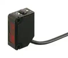


CX-441-P
Photo Sensor, 50 mm, PNP Open Collector, Reflective, 12 to 24 VDC, Cable, CX-400 Series
- Manufacturer: PANASONIC
- Product type:
- SVHC: To Be Advised
- Product Range: CX-400 Series
- Sensing Method: Reflective
- Connection Method: Cable
- Sensing Range Max: 50mm
- Sensor Output Type: PNP Open Collector
- Supply Voltage DC Max: 24V
- Supply Voltage DC Min: 12V
| Delivery and price | |
|---|---|
| Units per pack | 50 |
| Price | 87.0 € |
| Current stock | 10+ |
| Lead time | 30 days |
Amplifier Built-in

## Compact Photoelectric Sensor

CX-400 SERIES Ver.2

2022.6 a

* The contents of this catalog are as of October 2017. For the latest information, please visit our company website.

Compact Photoelectric Sensor Amplifier Built-in **CX-400 SERIES Ver.2**

2

**==> picture [107 x 204] intentionally omitted <==**

**----- Start of picture text -----**<br>
Recognition<br>Certified<br>(Some models only)<br>PNP output Light intensity Interference<br>type available monitor prevention<br>**----- End of picture text -----**<br>


## **Sensors that are environmentally and user friendly.**

**CX-41□/42□/49□**

## **Reducing environmental burdens further Up to 60% less power consumption**

## **Strong against oil and coolant liquids**

The lens material for the thru-beam type, retroreflective type (excluding the **CX-48□** ) and the diffuse reflective type are made of a strong acrylic that resists the harmful effects of coolants. These sensors can be used with confidence even around metal processing os* 2 machinery that disperses oil mists. The protection mechanism also conforms to IP67 (IEC).

The various lineup covers through the inclusion of a newly developed custom integrated circuit.The **CX-400** series achieves reductions in power consumption of up to 60%, averaging 44% reduction when upgrading due to its unique design. These sensors reduce carbon emissions and contribute to environmental friendliness. **Providing stable detection with low power consumption** a **Includes an analog CMOS processor ASIC**

|Test Oil|JIS Standard|Product Name|
|---|---|---|
|Lubricant|-|VelocityOil No. 3|
|Water-insoluble<br>cutting oil|2-5|Daphnecut AS-30D|
||2-11|Yushiron Oil No.2ac(Note)|
|Water-soluble<br>cutting oil|W1-1|Yushiron Lubic HWC68(Note)|
||W2-1|Yushiroken S50N(Note)|


Upgrade for up to Water-soluble cutting oil 60% reduction ~~ra4~~ , Previous **CX-482** New **CX-482 Strong agg ag aggainst ethanol** 25 mA 10 mA **Contributing to reduced carbon dioxide emissions** Electricity consumed by the **CX-400** series has been reduced on average The **CX-400** 10.5 mA. Calculating 8 hours/day, 260 contributes days (operating 5 days/week) for a total of 2,080 hours/year leads to: conforms to IP67 (IEC). **Approx. 84.6 t** annually in carbon dioxide reductions to the world Caution:  Set the **CX-48□** ~~a~~

1,000 hours; Immersion (depth 0 m); Insulation resistance 20 MΩ/250 V Note: Yushiron and Yushiroken are registered trademarks of Yushiro Chemical Industry Co., Ltd.

**CX-44□/48□**

**Strong agg ag aggainst ethanol**

A strong, ethanol resistant polycarbonate was used for the front and display covers. Safe even for installing near food processing machinery that disperses ethanol based detergents. The protection mechanism also > conforms to IP67 (IEC).

Caution:  Set the **CX-48□** so that cleaning liquid will not get on to the attached reflector.

Compact Photoelectric Sensor **CX-400 SERIES Ver.2**

3

## ~~ee~~ **APPLICATIONS**

**==> picture [460 x 287] intentionally omitted <==**

**----- Start of picture text -----**<br>
Detecting out of position tape  Detecting objects in dusty  Passage confirmation of object<br>feeder cassette environment on a conveyor belt<br>CX - 412<br>Slit mask<br>—- Joe CX - 491<br>Out of position<br>CX-411<br>Detecting transparent glass bottles Detecting a small tablet Detecting a biscuit<br>CX-441<br>CX-443<br>CX-481<br>oot -<br>**----- End of picture text -----**<br>


## ~~e~~ **BASIC PERFORMANCE** ~~e~~ **Strong infrared beam** a **CX-412/413 Can sense differences as small as 0.4 mm 0.016 in0.016 in,**

## **Can sense differences as small as 0.4 mm 0.016 in0.016 in, with hysteresis of 2 % or less CX-441/443**

Remarkable penetrating power enables applications such as package content detection.

An advanced optical system provides sensing performance that is 2.5 times approx. than conventional models. Even ultra-small differences of 0.4 mm 0.016 in can be detected accurately.

Note: When sensing utilizing penetrating power, make sure to verify using the actual sensor.

**==> picture [83 x 45] intentionally omitted <==**

**----- Start of picture text -----**<br>
Height differences of as<br>little as 0.4 mm 0.016 in<br>can be detected at a<br>setting distance of 20 mm<br>0.787 in<br>**----- End of picture text -----**<br>


## **CX-441/443**

## **Hardly affected by colors**

Both black and white objects can be sensed at the same distances. No adjuster control is needed, even when products of different colors are moving along the production line.

**Retroreflective type with polarizing filters CX-491**

Built-in polarizing filters ensure stable sensing even on a specular object.

**==> picture [53 x 24] intentionally omitted <==**

**----- Start of picture text -----**<br>
30 % higher<br>sensing sensing capability   capability<br>**----- End of picture text -----**<br>


**==> picture [25 x 18] intentionally omitted <==**

**----- Start of picture text -----**<br>
CX - 491<br>co x a<br>**----- End of picture text -----**<br>


The difference in sensing ranges is 1% or less between non-glossy white paper with a setting distance of 50 mm 1.969 in and non-glossy gray paper with a brightness level of 5. |

Compact Photoelectric Sensor **CX-400 SERIES Ver.2**

4

## ~~O~~ **BASIC PERFORMANCE** ~~O~~

## **CX-48□**

## **Introducing the transparent object sensing type sensor**

Transparent objects detectable with **CX-48□** (Typical examples)

Our unique optical system and transparent object sensing circuitry provide stable sensing of even thinner transparent objects than the conventional models.

|Sensing object|Sensing object size (mmin)|
|---|---|
|Glass sheet|50 × 501.969 × 1.969<br>t = 0.70.028|
|Cylindrical glass|ø50ø1.969ℓ = 501.969<br>t = 1.30.051|
|Acrylic board|50 × 501.969 × 1.969<br>t = 1.00.039|
|Styrol (Floppy case)|50 × 501.969 × 1.969<br>t = 0.90.035|
|Food wrapping film|50 × 501.969 × 1.969<br>t = 10 µm0.394 mil|
|Cigarette case film|50 × 501.969 × 1.969<br>t = 20 µm0.787 mil|
|Vinyl sack|50 × 501.969 × 1.969<br>t = 30 µm1.181 mil|
|PET bottle (500mℓ)|ø66ø2.598|


Reflector setting range **CX-481** : 300 to 500 mm 11.811 to 19.685 in, **CX-482** : 1 to 2 m 3.281 to 6.562 ft

**==> picture [27 x 6] intentionally omitted <==**

**----- Start of picture text -----**<br>
CX - 482<br>**----- End of picture text -----**<br>


[with the **RF-230** reflector at the optimum condition (Note)] Each object should pass across the beam at the center between the sensor and the reflector.

ℓ: Length of cylindrical glasses

t: Thickness of sensing object

Note: The optimum condition is defined as the condition in which the sensitivity level is set such that the stability indicator just lights up when the object is absent.

## **Long sensing range of 5 m 16.4 ft**

A long 5 m 16.4 ft sensing range is possible with the red LED type that is easy to align with the beam axis. Can be used for wide automatic door shutters.

**CX-493**

**Ultra-long sensing range of 30 m 98.4 ft CX-413**

The **CX-413** achieves the ultra-long sensing range of 30 m 98.4 ft. It can be used for a stacker crane or a multilevel parking structure.

## **ENVIRONMENTAL RESISTANCE**

## **CX-412/413**

## **Strong on dust and dirt**

Because the light source is an infrared light, it is strong on dust and dirt compared to the red beam type.

## **Strong even in cold environments**

## **Stronger noise resistance**

Fluorescent light

The **CX-400** series has a higher noise resistance than its previons model. By incorporating an inverter countermeasure circuit that appropriately shifts with peak wavelength, the sensor now resists high-frequency noise from high-voltage inverter motors and inverter lights more effectively.

**==> picture [44 x 6] intentionally omitted <==**

**----- Start of picture text -----**<br>
Inverter motor<br>**----- End of picture text -----**<br>


Stable performance can be maintained even in environments of –25 °C –13 °F.

## ~~OE~~ **ECO**

## **Thoroughly eliminating unnecessary waste, Reducing many environmental burdens**

The **CX-400** series has three different cable length types and uses very simple packaging to reduce waste. The bag is made of polyethylene and does not emit toxic gasses.

Compact Photoelectric Sensor **CX-400 SERIES Ver.2**

5

## ~~ee~~ **MOUNTING**

**Beam axis alignment made easy with a high luminance spot beam CX-423** These sensors have a ad high luminance red LED spot beam which provides bright visibility enabling the sensing position to be checked at a glance. p& Pm ahi, Because it achieved small beam spot approx. ø2 mm **CX-423** ø0.079 in at setting distance 100 mm 3.937 in, approx. ø5 mm ø0.197 in at setting Great visibility approx. ø2 mm distance 200 mm 7.874 in, ø0.079 in high luminance spot beam even the minutest object (at setting distance 100 mm 3.937 in) ’ 7 can be accurately detected.

**The bright spot makes beam axis alignment easy CX-44□** These sensors have a high luminance red spot that provides bright visibility. The sensing position can be checked at a glance. Because the **CX-441** sensor has the smallest spot in its class ø2 mm ø0.079 in approx., even Great visibility the minutest object can approx. ø2 mm be accurately detected. ø0.079 in high luminance spot **CX-441**

## ~~ee~~ **OPERABILITY**

**Reduction of volume adjustment labor CX-42□**

Because these sensors possess many variations depending on the sensing range, enables you to make optimal volume adjustment easily.

**==> picture [29 x 8] intentionally omitted <==**

**----- Start of picture text -----**<br>
CX-44□<br>**----- End of picture text -----**<br>


## **Can be used for sensing minute differences**

Equipped with a 5-turn adjuster so that even challenging range settings can be handled with ease.

**CX-422** : 800 mm 31.496 in **CX-421** : 300 mm 11.811 in **CX-424** : 100 mm 3.937 in GalD Narrow-view type **CX-423** : 70 to 300 mm 2.756 to 11.811 in

## ~~e~~ **VARIETIES** ~~e~~

## **Basic type available**

Omit the sensitivity adjuster and operation mode switch and release a basic type cable 0.5 m 1.641 ft in length. If the usage is clear, quick construction can be performed onsite without detailed adjustments and the cost can be controlled.

**CX-441/443**

**Select from 2 spot diameters as per the application CX-441/443** Within the choice of 50 mm 1.969 in sensing range sensors, we offer small spot approx. ø2 mm ø0.079 in type optimal for detecting minute object and large approx. ø6.5 mm ø0.256 in spot type capable of sensing object covered with holes and grooves.

## **Less processing time**

M8 plug-in connector type and M12 pigtailed type are available. This contributes to less time spent in setting up. In addition, cable types are available with cable lengths of 0.5 m 1.640 ft, 2 m 6.562 ft and 5 m 16.404 ft. This results in less wastage.

**==> picture [337 x 141] intentionally omitted <==**

**----- Start of picture text -----**<br>
po No unnecessary cables or terminal blocks<br>Cable type  CX-441<br>Spot diameter: ø2 mm<br>ø0.079 in<br>5 m 16.404 ft  approx.<br>St<br>[Positioning]<br>Great maintainability  Detects minute holes.<br>sD pe<br>2 m 6.562 ft  M8 plug-in<br>connector<br>type  Elbow  2 m 6.562 ft /<br>( 5 m 16.404 ft )<br>|,  & Straight  _i ( 2 m 5 m 6.562 ft16.404 ft  / )<br>| 0.5 m<br>1.640 ft  M12 pigtailed<br>type  Straight<br>2 m 6.562 ft /<br>| ( 5 m 16.404 ft )<br>**----- End of picture text -----**<br>


**==> picture [196 x 65] intentionally omitted <==**

**----- Start of picture text -----**<br>
CX-441 CX-443<br>Spot diameter: ø2 mm   Spot diameter: ø6.5 mm<br>ø0.079 in ø0.256 in<br>approx.  approx.<br>[Positioning]  Detection of presence /<br>Detects minute holes.  absence of objects<br>Ignores minute holes and<br>accurately detects objects.<br>**----- End of picture text -----**<br>


Compact Photoelectric Sensor **CX-400 SERIES Ver.2**

6

## ~~e~~ **FUNCTIONS** ~~e~~ **BGS/FGS functions make even the most challenging settings possible! CX-44□**

**==> picture [467 x 212] intentionally omitted <==**

**----- Start of picture text -----**<br>
Ce The BGS function is best suited for the following case The FGS function is best suited for the following case<br>Background not present Background present<br>BGS FGS<br>When object and background are separated When object and background are close together<br>_) _<br>When the object is glossy or uneven<br>Not affected if the background  Unaffected by gloss, color or<br>color changes or someone  uneven surfaces when sensing<br>passes behind the conveyor.  objects present on a conveyor belt.<br>DS<br>Caution:  Please use the FGS function together with a conveyor or other<br>background unit.<br>**----- End of picture text -----**<br>


**==> picture [228 x 71] intentionally omitted <==**

**----- Start of picture text -----**<br>
The FGS function is best suited for the following case<br>Background present<br>FGS<br>When object and background are close together<br>_<br>When the object is glossy or uneven<br>Unaffected by gloss, color or<br>uneven surfaces when sensing<br>**----- End of picture text -----**<br>


## > **BGS (Background suppression) function**

## **FGS (Foreground suppression) function**

The sensor judges that an object is present when no light is received at position B of the light-receiving element (2- segment element). Accordingly, even objects that are glossy can be sensed. This is useful if the object and background are close together, or if the object being sensed is glossy.

The sensor judges that an object is present when light is received at position A of the light-receiving element (2-segment element).

This is useful if the object and background are far apart. The distance adjustment method is the same as the conventional adjustment method for adjustable range reflective type sensors.

**==> picture [224 x 191] intentionally omitted <==**

**----- Start of picture text -----**<br>
OFFinthiscondiiononiyy OFF in this condition only ON ON in all other conditions in.alll other conditions<br>Object absent Object present For glossy object<br>OFF ON ON<br>A<br>Emitting<br>B element<br>Lens<br>Setting<br>distance<br>Conveyor Conveyor Conveyor<br>ee<br>Light received Light received  Light is not<br>at position B at  position A received at<br>A conveyor or  position B, so a<br>other  object is judged<br>back-ground  to be present<br>must be present<br>**----- End of picture text -----**<br>


**==> picture [160 x 87] intentionally omitted <==**

**----- Start of picture text -----**<br>
OFF ON<br>Light received at (Light received at element A)<br>element B, or Element A<br>light not received<br>Element B<br>Moving object Object<br>in the back<br>Setting distance<br>Background<br>**----- End of picture text -----**<br>


## **Strong against interference**

The interference prevention function lets two sensors to be mounted close together precisely.

**==> picture [228 x 77] intentionally omitted <==**

**----- Start of picture text -----**<br>
Interference<br>Retroreflective type<br>prevention  2 |<br>filter (Optional)  a Diffuse reflective type<br>Adjustable range reflective type<br>= s<br>Thru-beam type  Automatic<br>interference<br>Only  CX-411  prevention function<br>**----- End of picture text -----**<br>


Compact Photoelectric Sensor **CX-400 SERIES Ver.2**

7

## **ORDER GUIDE**

## **Standard type**

**==> picture [504 x 442] intentionally omitted <==**

**----- Start of picture text -----**<br>
Model No. (Note 1) Output  Emitting<br>Type Appearance Sensing range operation element<br>NPN output PNP output<br>10 m 32.808 ft CX-411 CX-411-P Red LED<br>15 m 49.213 ft CX-412 CX-412-P<br>Infrared<br>LED<br>30 m 98.425 ft CX-413 CX-413-P<br>3 m 9.843 ft  (Note 2) CX-491 CX-491-P<br>Red LED<br>5 m 16.404 ft (Note 2) CX-493 CX-493-P<br>50 to 500 mm 1.969 to 19.685 in (Note 2) CX-481 CX-481-P<br>Switchable<br>either Light-ON<br>50 to 1,000mm 1.969 to 39.37 in (Note 2) CX-483 CX-483-P or Dark-ON Infrared LED<br>0.1 to 2 m 0.328 to 6.562 ft (Note 2) CX-482 CX-482-P<br>100 mm 3.937 in CX-424 CX-424-P<br>Infrared<br>300 mm 11.811 in CX-421 CX-421-P<br>LED<br>800 mm 31.496 in CX-422 CX-422-P<br>70 to 300 mm 2.756 to 11.811 in CX-423 CX-423-P Red LED<br>CX-441 CX-441-P<br>2 to 50 mm 0.079 to 1.969 in<br>CX-443 CX-443-P<br>Switchable either<br>Detection-ON or  Red LED<br>Detection-OFF<br>15 to 100 mm 0.591 to 3.937 in CX-444 CX-444-P<br>20 to 300 mm 0.787 to 11.811 in CX-442 CX-442-P<br>Thru-beam<br>Long sensing  range<br>With polarizing filters<br>Retroreflective Long sensing  range<br>For transparent  object sensing<br>Diffuse reflective<br>Narrow- view<br>Adjustable range reflective Small  spot<br>**----- End of picture text -----**<br>


NOTE: Mounting bracket is not supplied with the sensor. Please select from the range of optional sensor mounting brackets.

Notes: 1)  The model No. with “ **E** ” shown on the label affixed to the thru-beam type sensor is the emitter, “ **D** ” shown on the label is the receiver.

- 2)  The sensing range of the retroreflective type sensor is specified for the **RF-230** (optional) reflector. The sensing range represents the actual sensing range of the sensor. The sensing ranges itemized in “A” of the table below may vary depending on the shape of sensing object. Be sure to check the operation with the actual sensing object.

**==> picture [410 x 58] intentionally omitted <==**

**----- Start of picture text -----**<br>
Sensing CX-491□  CX-493□  CX-481□  CX-483□  CX-482□<br>range: A<br>0 to 3 m 0 to 5 m 50 to 500 mm 50 to 1,000 mm 0.1 to 2 m<br>Sensingobject A 0 to 9.843 ft 0 to 16.404 ft 1.969 to 19.685 in 1.969 to 39.37 in 0.328 to 6.562 ft<br>0.1 to 3 m  0.1 to 5 m  100 to 500 mm  100 to 1,000 mm 0.8 to 2 m<br>Setting range B<br>of the reflector: B 0.328 to 9.843 ft 0.328 to 16.404 ft 3.937 to 19.685 in 3.937 to 39.37 in 2.625 to 6.562 ft<br>Sensor Reflector<br>**----- End of picture text -----**<br>


Compact Photoelectric Sensor **CX-400 SERIES Ver.2**

8

## **ORDER GUIDE**

**Basic type** (Without operation mode switch and sensitivity adjuster. Cable is 0.5 m 1.640 ft long.)

**==> picture [503 x 184] intentionally omitted <==**

**----- Start of picture text -----**<br>
Model No.(Note 1) Output  Emitting<br>Type Appearance Sensing range operation element<br>NPN output PNP output<br>CX-411A-C05 CX-411A-P-C05 Light-ON<br>10 m 32.808 ft Red LED<br>CX-411B-C05 CX-411B-P-C05 Dark-ON<br>CX-412A-C05 CX-412A-P-C05 Light-ON<br>Infrared<br>15 m 49.213 ft<br>LED<br>CX-412B-C05 CX-412B-P-C05 Dark-ON<br>CX-491A-C05-Y CX-491A-P-C05-Y Light-ON<br>3 m 9.843 ft (Note 3) Red LED<br>CX-491B-C05-Y CX-491B-P-C05-Y Dark-ON<br>Optional (Note 2)<br>Thru-beam<br>Long sensing range<br>Retroreflective With polarizing filters<br>**----- End of picture text -----**<br>


NOTE: Mounting bracket is not supplied with the sensor. Please select from the range of optional sensor mounting brackets.

Notes: 1)  The model No. with “ **E** ” shown on the label affixed to the thru-beam type sensor is the emitter, “ **D** ” shown on the label is the receiver.

- 2)  The reflector is an option. The sensing range of the leflector is specified for the **RF-230** .

3)  The sensing range of the retroreflective type sensor is specified for the **RF-230** (optional) reflector (p.10). The sensing range represents the actual sensing range of the sensor. The sensing range : A of the table below may vary depending on the shape of sensing object. Be sure to check the operation with the actual sensing object.

**==> picture [222 x 65] intentionally omitted <==**

**----- Start of picture text -----**<br>
Sensing CX-491 □<br>range: A<br>0 to 3 m<br>Sensingobject A 0 to 9.843 ft<br>0.1 to 3 m<br>Setting range B<br>of the reflector: B 0.328 to 9.843 ft<br>Sensor Reflector<br>(Optional)<br>**----- End of picture text -----**<br>


Compact Photoelectric Sensor **CX-400 SERIES Ver.2**

9

## ~~we~~ **ORDER GUIDE**

## **0.5 m 1.640 ft / 5 m 16.404 ft cable length types**

- 0.5 m 1.640 ft / 5 m 16.404 ft cable length types (standard: 2 m 6.562 ft, basic: 0.5 m 1.640 ft) are also available. When ordering this type, suffix “ **-C05** ” for the 0.5 m 1.640 ft cable length type, “ **-C5** ” for the 5 m 16.404 ft cable length type to the model No. (Excluding **CX-44□** and basic type)

(e.g.)  0.5 m 1.640 ft cable length type of **CX-411-P** is “ **CX-411-P-C05** ”

- 5 m 16.404 ft cable length type of **CX-411-P** is “ **CX-411-P-C5** ”

## **M8 plug-in connector type, M12 pigtailed type**

M8 plug-in connector type and M12 pigtailed type are also available.

When ordering this type, suffix “ **-Z** ” for the M8 connector type, “ **-J** ” for the M12 pigtailed type to the model No. (Please note that M12 pigtailed type is not available for **CX-44□** . Excluding basic type)

- (e.g.)  M8 connector type of **CX-411-P** is “ **CX-411-P-Z** ”

   - M12 pigtailed type of **CX-411-P** is “ **CX-411-P-J** ”

## **•** Mating cable (2 cables are required for the thru-beam type.)

**==> picture [56 x 10] intentionally omitted <==**

**----- Start of picture text -----**<br>
Mating cable<br>**----- End of picture text -----**<br>


|Type|Type|Model No.|Cable length|Description|
|---|---|---|---|---|
|For M8 plug-in<br>connector type|Straight|**CN-24A-C2**|2 m6.562 ft|Can be used with all models|
|||**CN-24A-C5**|5 m16.404 ft||
||Elbow|**CN-24AL-C2**|2 m6.562 ft||
|||**CN-24AL-C5**|5 m16.404 ft||
|For M12<br>pigtailed type|2-core|**CN-22-C2**<br>**CN-22-C5**|2 m6.562 ft<br>5 m16.404 ft|For thru-beam type emitter<br>(2-core)|
||4-core|**CN-22-C5**<br>**CN-24-C2**|5 m16.404 ft<br>2 m6.562 ft|(2-core)<br>Can be used with all models|
|||**CN-24-C5**|5 m16.404 ft||


**==> picture [158 x 122] intentionally omitted <==**

**----- Start of picture text -----**<br>
• CN-24A-C2 • CN-24AL-C2<br>CN-24A-C5 CN-24AL-C5<br>ø9 mm ø0.354 in  23.1 mm 0.909 in  ø9 mm ø0.354 in<br>LW 31.4 mm  . .<br>1.236 in  20.5 mm<br>0.807 in<br>ø4 mm<br>ø0.157 in<br>a —<br>**----- End of picture text -----**<br>


ø4 mm ø0.157 in

## **Package without reflector**

NPN output type: **CX-491-Y** PNP output type: **CX-491-P-Y**

## **Accessory**

**==> picture [72 x 12] intentionally omitted <==**

**----- Start of picture text -----**<br>
• RF-230  (Reflector)<br>**----- End of picture text -----**<br>


**==> picture [130 x 76] intentionally omitted <==**

**----- Start of picture text -----**<br>
• CN-22-C2 ,  CN-22-C5<br>CN-24-C2 ,  CN-24-C5<br>ø14 mm  ø5 mm<br>ø0.551 in  ø0.197 in<br>300 mm<br>11.811 in<br>**----- End of picture text -----**<br>


Compact Photoelectric Sensor **CX-400 SERIES Ver.2**

10

## ~~Be~~ **OPTIONS**

**==> picture [508 x 484] intentionally omitted <==**

**----- Start of picture text -----**<br>
|||||||||||||||
|---|---|---|---|---|---|---|---|---|---|---|---|---|---|
|Model No.|Sensing range|Min. sensing object|
|Designation|Slit size|
|Slit mask|Sensor|Slit on one side|Slit on both sides|Slit on one side|Slit on both sides|
|||ee|
|ee|[ee]|CX-411|□|400 mm 15.748 in|20 mm 0.787 in|
|||ø0.5 mm|ee|
|OS-CX-05|CX-412|□|600 mm 23.622 in|30 mm 1.181 in|ø12 mm ø0.472 in|ø0.5 mm ø0.020 in|
|ø0.020 in|
|||ee|ee|
|CX-413|□|1,200 mm 47.242 in|60 mm 2.362 in|
|Round slit mask|||CX-411|□|ee|900 mm 35.433 in|100 mm|ee|3.937 in|ø1 mm ø0.039 in|
|For thru-|||ø1 mm|ee|ee|
|OS-CX-1|CX-412|□|1.35 m 4.429 ft|150 mm 5.906 in|ø12 mm ø0.472 in|
|beam type|||ø0.039 in|ee|ee|ø1.5 mm ø0.059 in|
|( sensor only|)|||CX-413|□|ee|2.7 m 8.857 ft|300 mm|ee|11.811 in|
|CX-411|□|2 m 6.562 ft|400 mm 15.748 in|ø2 mm ø0.079 in|
|||ø2 mm|ee|ee|
|OS-CX-2|CX-412|□|3 m 9.843 ft|600 mm 23.622 in|ø12 mm ø0.472 in|
|||ø0.079 in|ee|ee|ø3 mm ø0.118 in|
|CX-413|□|6 m 19.685 ft|1,200 mm 47.242 in|
|||ee|ee|
|CX-411|□|2 m 6.562 ft|400 mm 15.748 in|
|||0.5 × 6 mm|ee|ee|0.5 × 6 mm|
|OS-CX-05|×|6|||CX-412|□|0.020 × 0.236 in|ee|3 m 9.843 ft|600 mm|ee|23.622 in|ø12 mm ø0.472 in|0.020 × 0.236 in|
|CX-413|□|6 m 19.685 ft|1,200 mm 47.242 in|
|Rectangular slit|||ee|ee|
|mask|CX-411|□|3 m 9.843 ft|1 m 3.281 ft|
|For thru-|OS-CX-1|×|6|||CX-412|□|1 × 6 mm|ee|4.5 m 14.764 ft|1.5 m 4.921 ft|ee|ø12 mm ø0.472 in|1 × 6 mm|
|beam type|||0.039 × 0.236 in|ee|ee|0.039 × 0.236 in|
|( sensor only|)|||CX-413|□|ee|9 m 29.528 ft|3 m 9.843 ft|ee|
|CX-411|□|5 m 16.404 ft|2 m 6.562 ft|
|||2 × 6 mm|ee|ee|2 × 6 mm|
|OS-CX-2|×|6|||CX-412|□|0.079 × 0.236 in|ee|7.5 m 24.606 ft|3 m 9.843 ft|ee|ø12 mm ø0.472 in|0.079 × 0.236 in|
|CX-413|□|15 m 49.213 ft|6 m 19.685 ft|
|||ee|eeeee|
|Round slit mask|Round slit mask|
|(Stainless steel)|
|Designation|Model No.|Sensing range|Min. sensing object|• OS-CX-|□|
|Fitted on the front face|
|Interference|PF-CX4-V|of the sensor with one-|
|prevention filter|(Vertical, Silver)|2 pcs. per set|ø12 mm ø0.472 in|touch.|
|For|CX-411|□|5 m 16.404 ft (Note 1)|(Note 1)|
|(|only|)|PF-CX4-H|
|(Horizontal, Light brown)|2 pcs. per set|
|CX-491|□|1 m 3.281 ft (Note 2)|
|——tee eee|Rectangular slit mask|Rectangular slit mask|PLA|
|CX-493|□|1.5 m 4.921 ft (Note 2)|(Stainless steel)|
|• OS-CX-|□|×6|
|RF-210|||CX-481|□|ø30 mm ø1.181 in|Fitted on the front face|
|CX-483|□|0.1 to 0.3 m 0.328 to 0.984 ft (Note 2)|of the sensor with one-|
|Reflector|CX-482|□|0.1 to 0.6 m 0.328 to 1.969 ft (Note 2)|touch.|
|For retro-|
|reflective type|es|CX-491|□|1.5 m 4.921 ft (Note 2)|*||
|( sensor only|)|ee|CX-493|□|3 m 9.843 ft|ee|(Note 2)|NLA|
|RF-220|CX-481|□|50 to 300 mm 1.969 to 11.811 in (Note 2)|ø35 mm ø1.378 in|
|ee|eee|Interference|Interference prevention filter|
|CX-482CX-483|□□|0.1 to 1.3 m 0.1 to 0.7 m 0.328 to 4.265 ft0.328 to 2.297 ft (Note 2) (Note 2)|prevention filter|
|• PF-CX4-V|
|RF-230|(Note 3)|CX-491|□-|Y|□|3 m 9.843 ft (Note 2)|ø50 mm ø1.969 in|(Vertical, Silver)|

**----- End of picture text -----**<br>


- Notes: 1) Value when attached on both sides.

   - 2)  Set the distance between the **CX-491** □/ **493** □ and the reflector to 0.1 m 0.328 ft or more. However, see the table below for **CX-48** □.

   - The sensing range “A” may vary depending on the shape of sensing object. Be sure to check the operation with the actual sensing object.

**• PF-CX4-H** (Horizontal, Light brown) Two sets of **CX-411** □ o can be mounted close together.

**==> picture [477 x 150] intentionally omitted <==**

**----- Start of picture text -----**<br>
Sensing<br>range: A<br>J oF<br>Sensing<br>object Reflector<br>{ ] Setting rangeof the reflector: B o f • RF-210 11 mm • RF-220 8.3 mm • RF-230 8.3 mm<br>Sensor Reflector 33.3 mm 0.433 in 35.3 mm 0.327 in 50.3 mm 0.327 in<br>Model No. 1.311 in 1.390 in 1.98 in<br>A B 12.8 mm<br>Sensor Reflector 0.504 in<br>CX-481 □ RF-220 50 to 300 mm 1.969 to 11.811 in 100 to 300 mm 3.937 to 11.811 in<br>42.3 mm<br>RF-220 0.1 to 0.7 m 0.328 to 2.297 ft 0.2 to 0.7 m 0.656 to 2.297 ft 1.665 in<br>CX-483 □ RF-210 0.1 to 0.3 m 0.328 to 0.984 ft 0.1 to 0.3 m 0.328 to 0.984 ft<br>59.3 mm<br>RF-230 0.05 to 1 m 0.164 to 3.281 ft 0.1 to 1 m 0.328 to 3.281 ft 2.235 in<br>RF-220 0.1 to 1.3 m 0.328 to 4.265 ft 0.5 to 1.3 m 1.640 to 4.265 ft<br>CX-482 □<br>RF-210 0.1 to 0.6 m 0.328 to 1.969 ft 0.3 to 0.6 m 0.984 to 1.969 ft<br>**----- End of picture text -----**<br>


- 3) **RF-230** is attached to the retroreflective type sensor other than the basic type.

Compact Photoelectric Sensor **CX-400 SERIES Ver.2**

11

## ~~—_~~ **OPTIONS**

**==> picture [507 x 711] intentionally omitted <==**

**----- Start of picture text -----**<br>
Reflector mounting bracket<br>Designation Model No. Description • MS-RF21-1 • MS-RF22<br>Protective mounting bracket for  RF-210<br>Reflector  MS-RF21-1 It protects the reflector from damage and maintains alignment.<br>mounting<br>bracket MS-RF22 For  RF-220<br>MS-RF23 For  RF-230<br>RF-11 • 0.8 m 0.5 m  Sensing range (Note 1.640 ft2.625 ft [ [ CX-491CX-493 2□]□]):  •• [Ambient temperature:  –25 to +50 °C][Ambient humidity: 35 to 85 % RH] –13 to +122 °F Two M3 (length 12 mm 0.472 inwashers are attached.) screws with  Two M3 (length 8 mm 0.315 inwashers are attached.) screws with<br>Notes: 1)  Keep the tape free from  • MS-RF23<br>•  Sensing range (Note 2):  stress. If it is pressed too<br>Reflective tape RF-12 1.2 m 0.7 m 2.297 ft3.937 ft [ [ CX-491CX-493 □]□] much, its capability may deteriorate.<br>0.1 to 0.6 m  2) Do not cut the tape. It will<br>0.328 to 1.969 ft [ CX-482 □] deteriorate the sensing  Two M4 (length 10 mm<br>performance. 0.394 in) screws with<br>RF-13 •  Sensing range (Note 3):  • [Ambient temperature:  –25 to +55 °C] –13 to +131 °F " washers are attached.<br>0.5 m 1.640 ft [ CX-491 □] • [Ambient humidit][y][: 35 to 85 % RH] Reflective tape<br>MS-CX2-1 Foot angled mounting bracket   • RF-11 • RF-12<br>It can also be used for mounting  RF-210 . 0.7 mm 0.7 mm<br>30 mm 0.028 in 0.028 in<br>Foot biangled mounting bracket   1.181 in<br>Sensor  MS-CX2-2 It can also be used for mounting  RF-210 . The thru-beam type  8 mm<br>mounting  sensor needs two  0.315 in<br>bracket (Note 1) Pf MS-CX2-4 Protective mounting bracket brackets. a” 0.984 in25 mm wa.<br>MS-CX2-5 Back biangled mounting bracket • RF-13<br>ee ee uy<br>MS-CX-3 Back angled mounting bracket<br>ee ee ee<br>MS-AJ1 Horizontal mounting type<br>Basic assembly<br>MS-AJ2 Vertical mounting type<br>Universal  30 mm<br>sensor  MS-AJ1-A Horizontal mounting type Lateral arm assembly 1.181 in<br>mounting stand  MS-AJ2-A Vertical mounting type<br>ee J<br>es MS-AJ1-M Horizontal mounting type Sensor mounting bracket<br>MS-AJ2-M Po Vertical mounting type Assembly for reflector • MS-CX2-1 • MS-CX2-2<br>Sensor checker  It is useful for beam alignment of thru-beam type sensors. The optimum<br>CHX-SC2<br>receiver position is given by indicators, as well as an audio signal.<br>ly?<br>Notes: 1)  The plug-in connector type sensor does not allow use of some sensor mounting brackets<br>because of the protrusion of the connector.<br>2) Set the distance between the sensor and the reflective tape to 0.1 m 0.328 ft ( CX-482 □: 0.4 m  SA<br>1.312 ft) or more. Two M3 (length 12 mm  Two M3  (length 12 mm<br>3)  Set the distance between the sensor and the reflective tape to 0.2 m 0.656 ft or more. 0.472 inwashers are attached.) screws with  0.472 inwashers are attached.) screws with<br>• MS-CX2-4 • MS-CX2-5<br>Universal sensor mounting stand<br>• MS-AJ1 • MS-AJ1-A • MS-AJ1-M<br>Swivel:  With the lateral arm, the  Swivel:  Swivel:<br>360˚ rotation sensor can sense from  360˚ rotation 360˚ rotation<br>above a production line.<br>Elevationangle: ±45˚45˚45˚ si8 150 mm 5.906 in approx.Height adjustment: Forward / back adjustment: 130 mm approx. 5.118 in 150 mm 5.906 in approx.Height adjustment: Elevationangle: ±45˚45˚45˚ -RE Height adjustment:150 mm 5.906 in approx. • MS-CX-3 ran Two M3 (length 14 mm 0.551 inwashers are attached.) screws with  Two M3 (length 12 mm 0.472 inwashers are attached. fC ) screws with<br>360˚<br>Mounting hole  Mounting hole<br>Q for M6 screw rotation cas | for M6 screw 3<br>45˚ [45˚] Mounting<br>Angle adjustment: ±45˚ hole for<br><s M6 screw fe b<br>• MS-AJ2 • MS-AJ2-A • MS-AJ2-M<br>IZ<br>Swivel:  With the lateral arm, the  Swivel:  Swivel:<br>360˚ rotation sensor can sense from  360˚ rotation 360˚ rotation Two M3 (length 12 mm 0.472 in)<br>above a production line. screws with washers are attached.<br>45˚ Height  Forward / back Height<br>adjustment: adjustment:  Height  45˚ adjustment: Sensor checker<br>45˚ 150 mm  130 mm 5.118 in adjustment: 150 mm<br>Elevationangle: ±45˚ 5.906 in approx. approx. 150 mm 5.906 in approx. Elevationangle: ±45˚45˚ 5.906 in approx. • CHX-SC2<br>tL Mounting hole for M6 screw 360˚ @ 7 Mounting hole  5<br>rotation 45˚ [45˚] Mounting  for M6 screw<br>Angle adjustment: ±45˚ hole for  Sensor checker<br>ba M6 screw SXZ<br>30 mm<br>1.181 in<br>0.5 mm<br>0.020 in<br>30 mm<br>1.181 in<br>POWER<br>CHX-SC2 LEVEL<br>**----- End of picture text -----**<br>


Compact Photoelectric Sensor **CX-400 SERIES Ver.2**

12

## **SPECIFICATIONS**

## **Standard type**

**==> picture [503 x 666] intentionally omitted <==**

**----- Start of picture text -----**<br>
Thru-beam Retroreflective<br>Type Diffuse reflective<br>Long sensing range With polarizing filters Long sensing range For transparent object sensing Narrow-view<br>NPN output CX-411 CX-412 CX-413 CX-491 CX-493 CX-481 CX-483 CX-482 CX-424 CX-421 CX-422 CX-423<br>Item PNP output CX-411-P CX-412-P CX-413-P CX-491-P CX-493-P CX-481-P CX-483-P CX-482-P CX-424-P CX-421-P CX-422-P CX-423-P<br>CE marking directive compliance EMC Directive, RoHS Directive<br>10 m  15 m  30 m 3 m 9.843 ft 5 m 16.404 ft 50 to 500 mm   50 to 1,000 mm 0.1 to 2 m  100 mm  300 mm 800 mm  70 to 300 mm<br>Sensing range 32.808 ft 49.213 ft 98.425 ft (Note 2) (Note 2) 1.969 to 19.685 in (Note 2) 1.969 to 39.37 in (Note 2) 0.328 to 6.562 ft (Note 2) 3.937 in (Note 3) 11.811 in (Note 3) 31.496 in (Note 3) 2.756 to 11.811 in (Note 3)<br>ø50 mm ø1.969 in Opaque, translucent<br>ø50 mm ø1.969 in<br>Sensing object ø12 mm or more opaque object (Note 4) ø0.472 in or more opaque, translucent or  or more opaque or translucent  ø50 mm transparent, translucent or ø1.969 in or more  Opaque, translucent or transparent object (Note 5) or transparent object (Note 5)<br>specular object  opaque object (Note 2, 5) Min. sensing object: ø0.5 mm<br>(Note 2, 5) object (Note 2, 5) ( ø0.020 in copper wire )<br>Hysteresis 15 % or less of operation distance (Note 3)<br>Repeatability (perpendicular to sensing axis) 0.5 mm 0.020 in or less 1 mm 0.039 in or less 0.5 mm 0.020 in or less<br>Supply voltage 12 to 24 V DC ±10 %  Ripple P-P 10 % or less<br>Emitter: 15 mA or less Emitter: 20 mA or less Emitter: 25 mA or less 13 mA<br>Current consumption Receiver: 10 mA or less Receiver: 10 mA or less Receiver: 10 mA or less or less 10 mA or less 13 mA or less 15 mA or less<br><NPN output type> <PNP output type><br>NPN open-collector transistor PNP open-collector transistor<br>• Maximum sink current: 100 mA  • Maximum source current: 100 mA<br>Output • Applied voltage: 30 V DC or less (between output and 0 V) • Applied voltage: 30 V DC or less (between output and +V)<br>• Residual voltage:  2 V or less (at 100 mA sink current) • Residual voltage:  2 V or less (at 100 mA source current)<br>1 V or less (at 16 mA sink current) 1 V or less (at 16 mA source current)<br>Output operation Switchable either Light-ON or Dark-ON<br>Short-circuit protection Incorporated<br>Response time 1 ms or less 2 ms or less 1 ms or less<br>Operation indicator Orange LED (lights up when the output is ON)(incorporated on the receiver for thru-beam type)<br>Stability indicator Green LED (lights up under stable light received condition or stable dark condition)(incorporated on the receiver for thru-beam type)<br>Power indicator Green LED (lights up when the power<br>is ON) (incorporated on the emitter)<br>Sensitivity adjuster Continuously variable adjuster (incorporated on the receiver for thru-beam type)<br>Two units of sensors<br>can be mounted<br>Automatic interference  close together with<br>prevention function interference prevention  Incorporated (Two units of sensors can be mounted close together.)<br>filters. (Sensing range:<br>5 m 16.404 ft)<br>Protection IP67 (IEC)<br>Ambient temperature -25 to +55 °C -13 to +131 °F (No dew condensation or icing allowed), Storage: -30 to +70 °C -22 to +158 °F<br>Ambient humidity 35 to 85 % RH, Storage: 35 to 85 % RH<br>Ambient illuminance Incandescent light: 3,000 ℓx or less at the light-receiving face<br>Voltage withstandability 1,000 V AC for one min. between all supply terminals connected together and enclosure<br>Insulation resistance 20 MΩ, or more, with 250 V DC megger between all supply terminals connected together and enclosure<br>Vibration resistance 10 to 500 Hz frequency, 1.5 mm 0.059 in double amplitude (10 G max.) in X, Y and Z directions for two hours each<br>Shock resistance 500 m/s [2]  acceleration (50 G approx.) in X, Y and Z directions three times each<br>Emitting element (modulated) Red LED Infrared LED Red LED Infrared LED Infrared LED Red LED<br>Peak emission wavelength 680 nm 0.027 mil 870 nm 0.034 mil 850 nm 0.033 mil 680 nm 0.027 mil 650 nm 0.026 mil 870 nm 0.034 mil 860 nm 0.033 mil 645 nm 0.025 mil<br>Material Enclosure: PBT (Polybutylene terephthalate), Lens: Acrylic ( CX-48 □: Polycarbonate), Indicator cover: Acrylic ( CX-48 □: Polycarbonate)<br>Cable 0.2 mm [2]  3-core (thru-beam type emitter: 2-core) cabtyre cable, 2 m 6.562 ft long<br>Cable extension Extension up to total 100 m 328.084 ft is possible with 0.3 mm [2] , or more, cable (thru-beam type: both emitter and receiver)<br>Net Emitter: 45 g approx., Receiver: 50 g approx. 50 g approx.<br>Weight<br>Gross 100 g approx. 80 g approx. 60 g approx.<br>Accessories RF-230  (Reflector): 1 pc.<br>Notes: 1) Where measurement conditions have not been specified precisely, the conditions used were an ambient temperature of +23 °C +73.4 °F.<br>2)  The sensing range and the sensing object of the retroreflective type sensor are specified for the  RF-230  reflector. The sensing range represents the<br>actual sensing range of the sensor. The sensing range : A of the table below may vary depending on the shape of sensing object. Be sure to check the<br>operation with the actual sensing object.<br>Sensing CX-491 □  CX-493 □  CX-481 □  CX-483 □  CX-482 □<br>range: A<br>0 to 3 m  0 to 5 m 50 to 500 mm 50 to 1,000 mm 0.1 to 2 m<br>Sensing A<br>0 to 9.843 ft 0 to 16.404 ft 1.969 to 19.685 in 1.969 to 39.37 in 0.328 to 6.562 ft<br>object<br>Setting range B 0.1 to 3 m 0.1 to 5 m 100 to 500 mm 100 to 1,000 mm 0.8 to 2 m<br>of the reflector: B 0.328 to 9.843 ft 0.328 to 16.404 ft 3.937 to 19.685 in 3.937 to 39.37 in 2.625 to 6.562 ft<br>Sensor Reflector<br>Model No.<br>Environmental resistance<br>**----- End of picture text -----**<br>


- 3) The sensing range and hysteresis of the diffuse reflective type sensor are specified for white non-glossy paper (200 × 200 mm 7.874 × 7.874 in) as the object. 4) If slit masks (optional) are fitted, an object of ø0.5 mm ø0.020 in (using round slit mask) can be detected. 5) Make sure to confirm detection with an actual sensor before use.

Compact Photoelectric Sensor **CX-400 SERIES Ver.2**

13

## **SPECIFICATIONS**

## **Standard type**

**==> picture [504 x 640] intentionally omitted <==**

**----- Start of picture text -----**<br>
Type Adjustable range reflective<br>Small spot<br>NPN output CX-441 CX-443 CX-444 CX-442<br>Item PNP output CX-441-P CX-443-P CX-444-P CX-442-P<br>CE marking directive compliance EMC Directive, RoHS Directive<br>Adjustable range (Note 2) 20 to 50 mm 0.787 to 1.969 in 20 to 100 mm 0.787 to 3.937 in 40 to 300 mm 1.575 to 11.811 in<br>Sensing range (with white non-glossy paper) 2 to 50 mm 0.079 to 1.969 in 15 to 100 mm 0.591 to 3.937 in 20 to 300 mm 0.787 to 11.811 in<br>Hysteresis<br>2 % or less of operation distance 5 % or less of operation distance<br>(with white non-glossy paper)<br>Repeatability Along sensing axis: 1 mm 0.039 in or less, Perpendicular to sensing axis: 0.2 mm 0.008 in or less (with white non-glossy paper)<br>Supply voltage 12 to 24 V DC ±10 %  Ripple P-P 10 % or less<br>Current consumption  20 mA or less<br><NPN output type> <PNP output type><br>NPN open-collector transistor PNP open-collector transistor<br>• Maximum sink current: 100 mA • Maximum source current: 100 mA<br>Output • Applied voltage: 30 V DC or less (between output and 0 V) • Applied voltage: 30 V DC or less (between output and +V)<br>• Residual voltage:  2 V or less (at 100 mA sink current) • Residual voltage:  2 V or less (at 100 mA source current)<br>1 V or less (at 16 mA sink current) 1 V or less (at 16 mA source current)<br>Output operation Switchable either Detection-ON or Detection-OFF<br>Short-circuit protection Incorporated<br>Response time 1 ms or less<br>Operation indicator Orange LED (lights up when the output is ON)<br>Stability indicator Green LED (lights up under stable operating condition)<br>Distance adjuster 5-turn mechanical adjuster<br>Sensing mode BGS/FGS functions  Switchable with wiring of sensing mode selection input<br>Automatic interference prevention function (Note 3) Incorporated<br>Protection IP67 (IEC)<br>Ambient temperature –25 to +55 °C –13 to +131 °F (No dew condensation or icing allowed), Storage: –30 to +70 °C –22 to +158 °F<br>Ambient humidity 35 to 85 % RH, Storage: 35 to 85 % RH<br>Ambient illuminance Incandescent light: 3,000 ℓx or less at the light-receiving face<br>Voltage withstandability 1,000 V AC for one min. between all supply terminals connected together and enclosure<br>Insulation resistance 20 MΩ, or more, with 250 V DC megger between all supply terminals connected together and enclosure<br>Vibration resistance 10 to 500 Hz frequency, 3 mm 0.118 in double amplitude (20 G max) in X, Y and Z directions for two hours each<br>Shock resistance 500 m/s [2]  acceleration (50 G approx.) in X, Y and Z directions three times each<br>Emitting element Red LED (Peak emission wavelength: 650 nm 0.026 mil, modulated)<br>Spot diameter ø2 mm (at 50 mm ø0.079 in1.969 in approx. distance) ø6.5 mm (at 50 mm ø0.256 in1.969 in distance approx. ) ø9 mm (at 100 mm ø0.354 in3.937 in  approx.distance) ø15 mm (at 300 mm ø0.591 in11.811 in approx. distance)<br>Material Enclosure: PBT (Polybutylene terephthalate), Lens: Polycarbonate, Indicator cover: Polycarbonate<br>Cable 0.2 mm [2]  4-core cabtyre cable, 2 m 6.562 ft long<br>Cable extension Extension up to total 100 m 328.084 ft is possible with 0.3 mm [2] , or more, cable.<br>Weight Net weight: 55 g approx., Gross weight: 65 g approx.<br>Notes: 1)  Where measurement conditions have not been specified precisely, the conditions used were an ambient temperature of +23 °C +73.4 °F.<br>2)  The adjustable range stands for the maximum sensing range which can be set with the distance adjuster. The sensor can detect an object<br>2 mm 0.079 in [ CX-444 ( -P ): 15 mm 0.591 in,  CX-442 ( -P ): 20 mm 0.787 in], or more, away.<br>Actual sensing range  CX-441 □/ 443 □ CX-444 □ CX-442 □<br>of the sensor: A<br>2 to 50 mm 15 to 100 mm 20 to 300 mm<br>A<br>0.079 to 1.969 in 0.591 to 3.937 in 0.787 to 11.811 in<br>Adjustable range: B 20 to 50 mm 20 to 100 mm 40 to 300 mm<br>B<br>0.787 to 1.969 in 0.787 to 3.937 in 1.575 to 11.811 in<br>Sensing<br>object<br>Model No.<br>Environmental resistance<br>**----- End of picture text -----**<br>


- 3) Note that detection may be unstable depending on the mounting conditions or the sensing object. In the state that this product is mounted, be sure to check the operation with the actual sensing object.

Compact Photoelectric Sensor **CX-400 SERIES Ver.2**

14

## **SPECIFICATIONS**

## **Basic type**

**==> picture [503 x 537] intentionally omitted <==**

**----- Start of picture text -----**<br>
Thru-beam Retroreflective<br>Type Long sensing range With polarizing filters<br>Light-ON Dark-ON Light-ON Dark-ON Light-ON Dark-ON<br>NPN output CX-411A-C05 CX-411B-C05 CX-412A-C05 CX-412B-C05 CX-491A-C05-Y CX-491B-C05-Y<br>Item PNP output CX-411A-P-C05 CX-411B-P-C05 CX-412A-P-C05 CX-412B-P-C05 CX-491A-P-C05-Y CX-491B-P-C05-Y<br>CE marking directive compliance EMC Directive, RoHS Directive<br>Sensing range 10 m 32.808 ft 15 m 49.213 ft 3 m 9.843 ft (Note 2)<br>Sensing object ø12 mm ø0.472 in or more opaque object (Note 3) ø50 mm ø1.969 in or more transparent,<br>translucent or opaque object (Note 2, 4)<br>Hysteresis<br>Repeatability (perpendicular to sensing axis) 0.5 mm 0.020 in or less<br>Supply voltage 12 to 24 V DC ±10 %  Ripple P-P 10 % or less<br>Emitter: 15 mA or less Emitter: 20 mA or less<br>Current consumption Receiver: 10 mA or less Receiver: 10 mA or less 13 mA or less<br><NPN output type> <PNP output type><br>NPN open-collector transistor PNP open-collector transistor<br>• Maximum sink current: 100 mA  • Maximum source current: 100 mA<br>Output • Applied voltage: 30 V DC or less (between output and 0 V) • Applied voltage: 30 V DC or less (between output and +V)<br>• Residual voltage:  2 V or less (at 100 mA sink current) • Residual voltage:  2 V or less (at 100 mA source current)<br>1 V or less (at 16 mA sink current) 1 V or less (at 16 mA source current)<br>Short-circuit protection Incorporated<br>Response time 1 ms or less<br>Operation indicator Orange LED (lights up when the output is ON)(incorporated on the receiver for thru-beam type)<br>Stability indicator Green LED (lights up under stable light received condition or stable dark condition)(incorporated on the receiver for thru-beam type)<br>Power indicator Green LED (lights up when the power is ON) (incorporated on the emitter)<br>Sensitivity adjuster<br>Two units of sensors can be mounted<br>Automatic interference Incorporated (Two units of sensors can<br>close together with interference prevention<br>prevention function filters. (Sensing range: 5 m 16.404 ft) be mounted close together.)<br>Protection IP67 (IEC)<br>Ambient temperature –25 to +55 °C –13 to +131 °F (No dew condensation or icing allowed), Storage: –30 to +70 °C –22 to +158 °F<br>Ambient humidity 35 to 85 % RH, Storage: 35 to 85 % RH<br>Ambient illuminance Incandescent light: 3,000 ℓx or less at the light-receiving face<br>Voltage withstandability 1,000 V AC for one min. between all supply terminals connected together and enclosure<br>Insulation resistance 20 MΩ, or more, with 250 V DC megger between all supply terminals connected together and enclosure<br>Vibration resistance 10 to 500 Hz frequency, 1.5 mm 0.059 in double amplitude (10 G max.) in X, Y and Z directions for two hours each<br>Shock resistance 500 m/s [2]  acceleration (50 G approx.) in X, Y and Z directions three times each<br>Emitting element (modulated) Red LED Infrared LED Red LED<br>Peak emission wavelength 680 nm 0.027 mil 870 nm 0.034 mil 680 nm 0.027 mil<br>Material Enclosure: PBT (Polybutylene terephthalate), Lens: Acrylic, Indicator cover: Acrylic<br>Cable 0.2 mm [2]  3-core (thru-beam type emitter: 2-core) cabtyre cable, 0.5 m 1.640 ft long<br>Cable extension Extension up to total 100 m 328.084 ft is possible with 0.3 mm [2] , or more, cable (thru-beam type: both emitter and receiver)<br>Net Emitter: 20 g approx., Receiver: 20 g approx. 20 g approx.<br>Weight<br>Gross 50 g approx. 30 g approx.<br>Model No.<br>Environmental resistance<br>**----- End of picture text -----**<br>


Notes: 1) Where measurement conditions have not been specified precisely, the conditions used were an ambient temperature of +23 °C +73.4 °F. 2) The sensing range and the sensing object of the retroreflective type sensor are specified for the **RF-230** reflector (optional). The sensing range represents the actual sensing range of the sensor. The sensing range : A of the table below may vary depending on the shape of sensing object. Be sure to check the operation with the actual sensing object.

**==> picture [229 x 64] intentionally omitted <==**

**----- Start of picture text -----**<br>
Sensing CX-491 □<br>range: A<br>0 to 3 m<br>Sensing A<br>0 to 9.843 ft<br>object<br>0.1 to 3 m<br>Setting range B<br>of the reflector: B 0.328 to 9.843 ft<br>Sensor Reflector<br>(Optional)<br>**----- End of picture text -----**<br>


- 3) If slit masks (optional) are fitted, an object of ø0.5 mm ø0.020 in (using round slit mask) can be detected. 4) Make sure to confirm detection with an actual sensor before use.

Compact Photoelectric Sensor **CX-400 SERIES Ver.2**

15

## **I/O CIRCUIT AND WIRING DIAGRAMS**

## **NPN output type**

## **I/O circuit diagram**

**==> picture [238 x 100] intentionally omitted <==**

**----- Start of picture text -----**<br>
Color code / Connector pin No. of the connector type<br>D (Brown / 1) +V<br>(Black / 4) Load<br>D Output (Note 1) + 12 to 24 V DC<br>Tr ZD  100 mA max. – ±10 %<br>ZD (Blue / 3) 0 V<br>*1<br>(Pink / 2) Sensing mode<br>selection input (Note 2, 3)<br>Internal circuit User’s circuit<br>Sensor circuit<br>**----- End of picture text -----**<br>


- Notes: 1)  The emitter of the thru-beam type sensor does not incorporate the output.

   - 2)  Sensing mode selection input is incorporated only for the **CX-44** □ adjustable range reflective type. When using the **CX-44** □, be sure to wire the sensing mode selection input (pink / 2) as mentioned *[1] . Unstable operation may occur.

   - 3)  When the mating cable is connected to the plug-in connector type of **CX-44** □, its color is white.

## **Wiring diagram**

**==> picture [37 x 43] intentionally omitted <==**

**==> picture [187 x 74] intentionally omitted <==**

**----- Start of picture text -----**<br>
Brown<br>Load<br>Black (Note 1) + 12 to 24 V DC<br>– ±10 %<br>Blue<br>*1<br>Pink (Note 2, 3)<br>**----- End of picture text -----**<br>


Notes: 1) The emitter of the thru-beam type sensor does not incorporate the black wire.

   - 2)  The pink wire is incorporated only for the **CX-44** □ adjustable range reflective type. When using the **CX-44** □, be sure to wire the pink wire as mentioned *[1] . Unstable operation may occur.

   - 3)  When the mating cable is connected to the plug-in connector type of **CX-44** □, its color is white.

- *1

- Sensing mode selection input BGS function: Connect to 0 V FGS function: Connect to +V

*1

- Sensing mode selection input BGS function: Connect to 0 V FGS function: Connect to +V

Symbols ...  D : Reverse supply polarity protection diode ZD : Surge absorption zener diode Tr : NPN output transistor

## **Connector pin position**

## **M8 plug-in connector type M12 pigtailed type**

**==> picture [236 x 56] intentionally omitted <==**

**----- Start of picture text -----**<br>
2 4 2 1<br>Sensing mode Output Not +V<br>selection input (Note 1) connected<br>(Note 2)<br>1 3<br>+V 0 V 3 4<br>0 V Output (Note 1)<br>**----- End of picture text -----**<br>


- Notes: 1) The emitter of the thru-beam type sensor does not incorporate the output. 2)  Sensing mode selection input is incorporated only for the **CX-44** □ adjustable range reflective type. When using the **CX-44** □, be sure to wire the sensing mode selection input (pink / 2). Unstable operation may occur.

## **PNP output type**

## **I/O circuit diagram**

**==> picture [238 x 100] intentionally omitted <==**

**----- Start of picture text -----**<br>
Color code / Connector pin No. of the connector type<br>(Brown / 1) +V<br>ZD<br>Tr ZD  100 mA max. + 12 to 24 V DC<br>D (Black / 4) Output (Note 1) – ±10 %<br>Load<br>D (Blue / 3) 0 V<br>*1<br>(Pink / 2) Sensing mode<br>selection input (Note 2, 3)<br>Internal circuit User’s circuit<br>Sensor circuit<br>**----- End of picture text -----**<br>


- Notes: 1)  The emitter of the thru-beam type sensor does not incorporate the output.

   - 2)  Sensing mode selection input is incorporated only for the **CX-44** □ **-P** adjustable range reflective type. When using the **CX-44** □ **-P** , be sure to wire the sensing mode selection input (pink /

   - 2) as mentioned *[1] . Unstable operation may occur.

   - 3)  When the mating cable is connected to the plug-in connector type of **CX-44** □ **-P** , its color is white.

*1

**•** Sensing mode selection input BGS function: Connect to 0 V FGS function: Connect to +V

Symbols ...  D : Reverse supply polarity protection diode ZD : Surge absorption zener diode Tr : PNP output transistor

## **Wiring diagram**

**==> picture [37 x 43] intentionally omitted <==**

**==> picture [186 x 75] intentionally omitted <==**

**----- Start of picture text -----**<br>
Brown<br>Black (Note 1) + 12 to 24 V DC<br>– ±10 %<br>Load<br>Blue<br>*1<br>Pink (Note 2, 3)<br>**----- End of picture text -----**<br>


Notes: 1) The emitter of the thru-beam type sensor does not incorporate the black wire.

- 2)  The pink wire is incorporated only for the **CX-44** □ **-P** adjustable range reflective type. When using the **CX-44** □ **-P** , be sure to wire the pink wire as mentioned *[1] . Unstable operation may occur.

- 3)  When the mating cable is connected to the plug-in connector type of **CX-44** □ **-P** , its color is white.

*1

- Sensing mode selection input BGS function: Connect to 0 V FGS function: Connect to +V

## **Connector pin position**

## **M8 plug-in connector type M12 pigtailed type**

**==> picture [235 x 56] intentionally omitted <==**

**----- Start of picture text -----**<br>
2 4 2 1<br>Sensing mode   Output (Note 1) Not +V<br>selection input connected<br>(Note 2)<br>1 3<br>+V 0 V 3 4<br>0 V  Output (Note 1)<br>**----- End of picture text -----**<br>


Notes: 1) The emitter of the thru-beam type sensor does not incorporate the output.

- 2)  Sensing mode selection input is incorporated only for the **CX-44** □ **-P** adjustable range reflective type. When using the **CX-44** □ **-P** , be sure to wire the sensing mode selection input (pink / 2). Unstable operation may occur.

Compact Photoelectric Sensor **CX-400 SERIES Ver.2**

16

## **SENSING CHARACTERISTICS (TYPICAL)**

**==> picture [515 x 691] intentionally omitted <==**

**----- Start of picture text -----**<br>
CX-411□ Thru-beam type<br>Parallel deviation Angular deviation Parallel deviation with round Parallel deviation with round<br>slit masks (ø0.5 mm ø0.020 in) slit masks (ø1 mm ø0.039 in)<br>10 10 400 800 Slit on<br>32.808  32.808  15.748  Slit on  31.496 one side<br>one side<br>Emitter<br>5 Emitter  5 θ  L  200 Slit on  Emitter  400 Slit on  Emitter<br>16.404  16.404  7.874  both sides  15.748  both sides<br>ℓ L  Receiver  ℓ L  ℓ L<br>Receiver  Receiver  Receiver<br>0  0 0  0<br>400  200  0  200  400  40  20  0  20  40  20  10  0  10  20  40  20  0  20  40<br>15.748  7.874  7.874  15.748 Left  Center  Right  0.787  0.394  0.394  0.787  1.575  0.787  0.787  1.575<br>Left  Center  Right  Operating angle θ ( ° )  Left  Center  Right  Left  Center  Right<br>Operating point ℓ (mm in)  Operating point ℓ (mm in)  Operating point ℓ (mm in)<br>Parallel deviation with round Parallel deviation with rectangular Parallel deviation with rectangular Parallel deviation with rectangular<br>slit masks (ø2 mm ø0.079 in) slit masks (0.5 × 6 mm 0.020 × 0.236 in) slit masks (1 × 6 mm 0.039 × 0.236 in) slit masks (2 × 6 mm 0.079 × 0.236 in)<br>4  8<br>2 Slit on one side  2 Slit on one side Vertical  direction  13.123  Slit on one side Horizontal direction  Slit on one side Vertical direction  26.247  Slit on one side Horizontal direction<br>6.562  6.562  3 6<br>Slit on one side Horizontal  9.843  Slit on both sides Horizontal  19.685  Slit on one side Vertical<br>direction  direction  direction<br>3.281 1 Slit on both sides  Emitter  3.281 1 Horizontal direction Emitter  Slit on both sides  Vertical  direction  Slit on both sides  Horizontal  direction  Vertical direction Emitter  6.562 2 EmitHorizontal direction ter  Slit on both sides Vertical direction  Vertical  direction Emitter  13.123 4 Horizontal direction Emitter  Slit on both sides Horizontal direction  Slit on both sides Vertical direction  Emitter  Vertical  direction<br>ℓ L  ℓ L  ℓ L  3.281 1 ℓ L  ℓ L  6.562 2 ℓ L  ℓ L<br>Receiver  Receiver  Receiver  Receiver  Receiver  Receiver  Receiver<br>0 0 0 0<br>100  50  0  50  100  100  50  0  50  100  200  100  0  100  200  200  100  0  100  200<br>3.937  1.969  1.969  3.937  3.937  1.969  1.969  3.937  7.874  3.937  3.937  7.874  7.874  3.937  3.937  7.874<br>Left  Center  Right  (Down) Left  Center  Right (Up)  (Down) Left  Center  Right (Up)  (Down) Left  Center  Right (Up)<br>Operating point ℓ (mm in)  Operating point ℓ (mm in)  Operating point ℓ (mm in)  Operating point ℓ (mm in)<br>CX-412□ Thru-beam type<br>Parallel deviation Angular deviation Parallel deviation with round Parallel deviation with round<br>slit masks (ø0.5 mm ø0.020 in) slit masks (ø1 mm ø0.039 in)<br>20  20  800  2<br>65.617  65.617  31.496  Slit on  6.562  Slit on<br>one side  one side<br>15 15 600 1.5<br>49.213  49.213  Emitter  23.622  4.921<br>10 10 θ  L  400 1<br>32.808  Emitter  32.808  15.748  Emitter  3.281  Emitter<br>Receiver<br>16.404 5 ℓ L  16.404 5 2007.874  Slit on  both sides  ℓ  L  1.640 0.5 Slit on  both sides  ℓ  L<br>Rec e iver  Receiver  Receiver<br>0 0  0 0<br>1,000  500  0  500  1,000  40  20  0  20  40  100  50  0  50  100  200  100  0  100  200<br>39.370 19.685  19.685  39.370 Left  Center  Right  3.937  1.969  1.969  3.937  7.874  3.937  3.937  7.874<br>Left  Center  Right  Operating angle θ( ° )  Left  Center  Right  Left  Center  Right<br>Operating point ℓ (mm in)  Operating point ℓ (mm in)  Operating point ℓ (mm in)<br>Parallel deviation with round Parallel deviation with rectangular Parallel deviation with rectangular Parallel deviation with rectangular<br>slit masks (ø2 mm ø0.079 in) slit masks (0.5 × 6 mm 0.020 × 0.236 in) slit masks (1 × 6 mm 0.039 × 0.236 in) slit masks (2 × 6 mm 0.079 × 0.236 in)<br>4  4  8<br>13.123  Slit on  13.123  Slit on one side  Slit on one side  Slit on one side  Slit on one side  26.247  Slit on one side  Slit on one side<br>one side  Horizontal direction  Vertical direction  Vertical direction  Horizontal direction  Horizontal direction  Vertical direction<br>4<br>3 3 13.123  6<br>9.843  Slit on both sides  9.843  Slit on both sides Horizontal and Vertical direction  Slit on both sides Horizontal and Vertical direction  19.685  Slit on both sides Horizontal and Vertical direction<br>6.562 2 Emitter  6.562 2 Emitter Horizontal direction  Vertical  direction Emitter  6.562 2 EmitHorizontal  direction  ter  Vertical direction Emitter  13.123 4 Emitter  Horizontal  direction  Vertical  direction Emitter<br>3.281 1 ℓ  L  3.281 1 ℓ L  ℓ L  ℓ L  ℓ L  6.562 2 ℓ L  ℓ L<br>Receiver  Receiver  Receiver  Receiver  Receiver  Receiver  Receiver<br>0 0 0 0<br>400  200  0  200  400  400  200  0  200  400  400  200  0  200  400  800  400  0  400  800<br>15.748  7.874  7.874  15.748  15.748  7.874  7.874  15.748  15.748  7.874  7.874  15.748  31.496  15.748  15.748 31.496<br>Left  Center  Right  (Down) Left  Center  Right (Up)  (Down) Left  Center  Right (Up)  (Down) Left  Center  Right (Up)<br>Operating point ℓ (mm in)  Operating point ℓ (mm in)  Operating point ℓ (mm in)  Operating point ℓ (mm in)<br>)  )<br>) ftSetting distance L (m  ) ftSetting distance L (m  Setting distance L (mm in Setting distance L (mm in<br>)  )  )  )<br>ft ft ft ft<br>Setting distance L (m  Setting distance L (m  Setting distance L (m  Setting distance L (m<br>) ftSetting distance L (m  ) ftSetting distance L (m  )Setting distance L (mm in ) ftSetting distance L (m<br>)  )  )  )<br>ft ft ft ft<br>Setting distance L (m  Setting distance L (m  Setting distance L (m  Setting distance L (m<br>**----- End of picture text -----**<br>


Compact Photoelectric Sensor **CX-400 SERIES Ver.2**

17

## **SENSING CHARACTERISTICS (TYPICAL)**

**==> picture [510 x 683] intentionally omitted <==**

**----- Start of picture text -----**<br>
CX-491□ Retroreflective type CX-493□ Retroreflective type<br>Parallel deviation Angular deviation Parallel deviation Angular deviation<br>4  4  8  8<br>13.123  13.123  Reflector  26.247  26.247<br>angular<br>deviation<br>3 3 6  6<br>9.843  Reflector  ( RF-230 )  9.843  Sensor angular  19.685  19.685  Reflector angular<br>6.562 3.281 12 Sensor ℓ L  6.562 3.281 21 Reflector deviation angular  Sensor  Sensor ( θ  RF-230 L  )  Reflector (deviation  Reflector  angular deviation  RF-230 θ Sensor L  )  13.123 6.562 2 4  Reflector  ( RF-230 ℓ  L )  13.123 6.562 2 4  Reflector ( deviation  angular angular Sensor Sensor θ RF-230 L  )  Reflector angular deviation (Reflector deviation  RF-230 Sensor angular deviation )  θ  L<br>0 0 0 Sensor  0 Sensor  Sensor<br>200  100  0  100  200  40  20  0  20  40  200  100  0  100  200  40  20  0  20  40<br>7.874  3.937  3.937  7.874  Left  Center  Right  7.874  3.937  3.937  7.874  Left  Center  Right<br>Left  Center  Right  Operating angle θ ( ° )  Left  Center  Right  Operating angle θ( ° )<br>Operating point ℓ (mm in)  Operating point ℓ (mm in)<br>CX-481□ Retroreflective type CX-482□ Retroreflective type<br>Parallel deviation Angular deviation Parallel deviation Angular deviation<br>800 800 Sensor angular<br>31.496  31.496  deviation<br>Reflector ( RF-230 )<br>600 600 θ  L  6.562 2  6.562 2<br>23.622  Reflector   23.622  Sensor  Reflector<br>( RF-230 )  ( RF-230 )  Sensor  Reflector<br>15.748 400 ℓ  L  15.748 400 Reflector  ℓ L  angular deviation  angular deviation<br>200 Sensor  200 Reflector angular deviation  Reflector (angular deviation  RF-230 )  3.281 1  Sensor  3.281 1  deviation angular Sensor  Reflector angular deviation<br>7.874  7.874  Sensor angular  θ  L  θ  L ( [Reflector ] RF-230 )  (Reflector  RF-230 )  θ  L<br>deviation  Sensor  Sensor  Sensor<br>0 0 0  0<br>100  50  0  50  100  40  20  0  20  40  200  100  0  100  200  40  20  0  20  40<br>3.937  1.969  1.969  3.937  Left  Center  Right  7.874  3.937  3.937  7.874  Left  Center  Right<br>Left  Center  Right  Operating angle θ ( ° )  Left  Center  Right  Operating angle θ ( ° )<br>Operating point ℓ (mm in)  Operating point ℓ (mm in)<br>CX-424□ Diffuse reflective type<br>Sensing field Correlation between sensing object size and sensing range<br>As the sensing object size becomes smaller than the standard<br>200 × 200 mm  size (white non-glossy paper 200 × 200 mm 7.874 × 7.874 in), the<br>100 3.937  7.874 × 7.874 in White non-glossy paper  100 3.937  sensing range shortens, as shown in the left graph.<br>ℓ  For plotting the left graph, the sensitivity has been set such that<br>L  a 200 × 200 mm 7.874 × 7.874 in white non-glossy paper is just<br>a × a mm   detectable at a distance of 100 mm 3.937 in.<br>50  Sensor  50  White non-glossy paper<br>1.969  1.969<br>L<br>Sensor<br>0<br>20  10  0  10  20  0  50  100  150  200<br>0.787  0.394  0.394  0.787  1.969  3.937  5.906  7.874<br>Left  Center  Right  White non-glossy paper<br>Operating point ℓ (mm in)  side length a (mm in)<br>CX-421□ Diffuse reflective type<br>Sensing field Correlation between sensing object size and sensing range<br>15.748 400  200 × 200 mm  15.748 400  As the sensing object size becomes smaller than the standard<br>7.874 × 7.874 in  size (white non-glossy paper 200 × 200 mm 7.874 × 7.874 in), the<br>300  White non- glossy paper  300  sensing range shortens, as shown in the left graph.<br>11.811  ℓ  L  11.811  For plotting the left graph, the sensitivity has been set such that<br>a 200 × 200 mm 7.874 × 7.874 in white non-glossy paper is just<br>200 Sensor  200  a × a mm   detectable at a distance of 300 mm 11.811 in.<br>7.874  7.874  White non-<br>glossy paper<br>100 100  L<br>3.937  3.937<br>Sensor<br>0<br>40  20  0  20  40  0  50  100  150  200<br>1.575  0.787  0.787  1.575  1.969  3.937  5.906  7.874<br>Left  Center  Right  White non-glossy paper<br>Operating point ℓ (mm in)  side length a (mm in)<br>) ftSetting distance L (m  ) ftSetting distance L (m  ) ftSetting distance L (m  ) ftSetting distance L (m<br>) in ) in ) ft ) ft<br>Setting distance L (mm  Setting distance L (mm  Setting distance L (m  Setting distance L (m<br>)<br>in )<br>in<br>Setting distance L (mm  Sensing range L (mm<br>)  )<br>in in<br>m<br>ing range L (m<br>Sens<br>Setting distance L (mm<br>**----- End of picture text -----**<br>


Compact Photoelectric Sensor **CX-400 SERIES Ver.2**

18

## **SENSING CHARACTERISTICS (TYPICAL)**

Diffuse reflective type

## **CX-422□**

**==> picture [255 x 318] intentionally omitted <==**

**----- Start of picture text -----**<br>
Sensing field<br>1,000  800<br>39.370  200 × 200 mm  31.496<br>7.874 × 7.874 in<br>White non-<br>glossy paper  a × a mm  White non-<br>500 ℓ  L  400 glossy paper<br>19.685  15.748<br>L<br>Sensor<br>Sensor<br>0<br>40  20  0  20  40  0  50  100  150  200<br>1.575  0.787  0.787  1.575  1.969  3.937  5.906  7.874<br>Left  Center  Right  White non-glossy paper<br>Operating point ℓ (mm in)  side length a (mm in)<br>CX-423□<br>Sensing field<br>White  White<br>200 200<br>7.874  7.874<br>N6<br>N6<br>100 200 × 200 mm  100<br>3.937  7.874 × 7.874 in 3.937<br>Non-glossy paper  a × a mm<br>ℓ  Non-glossy paper  L<br>L<br>Sensor  Sensor<br>0<br>2  1  0  1  2  0  50  100  150  200<br>0.079  0.039  0.039  0.079  1.969  3.937  5.906  7.874<br>Left  Center  Right  Non-glossy paper<br>Operating point ℓ (mm in)  side length a (mm in)<br>)  )<br>in in<br>m<br>ing range L (m<br>Sens<br>Setting distance L (mm<br>) in ) in<br>m<br>ing range L (m<br>Setting distance L (mm  Sens<br>**----- End of picture text -----**<br>


## **Correlation between sensing object size and sensing range**

As the sensing object size becomes smaller than the standard size (white non-glossy paper 200 × 200 mm 7.874 × 7.874 in), the sensing range shortens, as shown in the left graph.

For plotting the left graph, the sensitivity has been set such that a 200 × 200 mm 7.874 × 7.874 in white non-glossy paper is just detectable at a distance of 800 mm 31.496 in.

Diffuse reflective type

## **Correlation between sensing object size and sensing range**

As the sensing object size becomes smaller than the standard size (white non-glossy paper 200 × 200 mm 7.874 × 7.874 in), the sensing range shortens, as shown in the left graph.

For plotting the left graph, the sensitivity has been set such that a 200 × 200 mm 7.874 × 7.874 in white non-glossy paper is just detectable at a distance of 200 mm 7.874 in. Contact us for the sensing characteristics of 300 mm 11.811 in distance. Please contact us for the sensing field at the setting distance 300 mm 11.811 in.

## **Correlation between lightness and sensing range**

## **Emitted beam**

**==> picture [386 x 135] intentionally omitted <==**

**----- Start of picture text -----**<br>
250<br>The sensing region is  9.843<br>7.874200 represented by oblique lines in the left figure.  7.874 200  ø5 mm ø0.197 in<br>However, the sensitivity should  150<br>be set with an enough margin  5.906  ø2.5 mm  ø0.098 in<br>because of slight variation in  110 ø2 mm<br>3.937100 Sensingregion products. 1004.3313.937  ø0.079 in ø2.2 mm ø0.087 in<br>50 ø4 mm<br>1.969  ø0.157 in<br>0 0<br>N2 N4 N6 N8<br>Dark Lig htness Light Lightness shown on the left may<br>differ slightly from the actual<br>N1 N2 N3 N4 N5 N6 N7 N8 N9 object condition.<br>)in )<br>in<br>Distance L (mm<br>Sensing range L (mm  Visible spot range<br>**----- End of picture text -----**<br>


Compact Photoelectric Sensor **CX-400 SERIES Ver.2**

19

## **SENSING CHARACTERISTICS (TYPICAL)**

**==> picture [506 x 706] intentionally omitted <==**

**----- Start of picture text -----**<br>
CX-441□ Adjustable range reflective type<br>Sensing fields Emitted beam<br>•  Setting distance: 25 mm 0.984 in •  Setting distance: 50 mm 1.969 in<br>40 80 80<br>1.575 White non- 3.150 White non- 3.150<br>glossy paper glossy paper<br>30 Gray non-glossy paper 60 Gray non-glossy paper 60<br>1.181 Lightness: 5 2.362 Lightness: 5 2.362<br>50<br>1.969 ø2 mm 0.079 in<br>20 40 40<br>0.787 50 × 50 mm 1.969 × 1.969 inNon-glossy paper 1.575 Non-glossy paper50 × 50 mm 1.969 × 1.969 in 1.5751.18130 ø2 mm ø3 mm 0.079 in0.118 in<br>0.39410 L ℓ 0.78720 L ℓ 0.78720 ø3 mm 0.118 in<br>Sensor Sensor<br>0 0   0<br>4 2 0 2 4 4 2 0 2 4<br>0.157 0.079 0.079 0.157 0.157 0.079 0.079 0.157<br>Left Center Right Left Center Right<br>Operating point ℓ (mm in)  Operating point ℓ (mm in)<br>Correlation between color Correlation between material<br>(50 × 50 mm 1.969 × 1.969 in construction paper) and sensing range (50 × 50 mm 1.969 × 1.969 in) and sensing range<br>50 These bars indicate the  50 These bars indicate<br>1.969 sensing range with the  1.969<br>the sensing range<br>respective colors when<br>with the respective<br>the distance adjuster is<br>objects when the<br>0.98425 … [50 mm] 1.969 in set to a sensing range of 50 mm 1.969 in and  0.98425 … [50 mm] 1.969 in distance adjuster is set to a sensing range<br>…25 mm0.984 in 25 mm respectively, with white 0.984 in long,  …25 mm0.984 in of 50 mm and 25 mm 1.969 in0.984 in<br>color.<br>long, respectively,<br>0 The sensing range also  0<br>with white non-glossy<br>varies depending on<br>paper.<br>material.<br>CX-443□ Adjustable range reflective type<br>Sensing fields Emitted beam<br>•  Setting distance: 25 mm 0.984 in •  Setting distance: 50 mm 1.969 in<br>1.57540 50 × 50 mm Non-glossy paper1.969 × 1.969 in 3.15080 50 × 50 mm Non-glossy paper1.969 × 1.969 in 3.150 80<br>30 L ℓ 60 L ℓ 60<br>1.181 2.362 2.362<br>Sensor Sensor 50<br>1.969  ø6.5 mm 0.256 in<br>0.78720 glossy paperWhite non- 1.57540 glossy paperWhite non- 1.575 4030 ø6.2 mm 0.244 in<br>0.39410 Gray non-glossy paperLightness: 5 0.78720 Gray non-glossy paperLightness: 5 0.787 1.181 20 ø5.9 mm ø5.3 mm 0.232 in 0.209 in<br>0 0   0<br>4 2 0 2 4 4 2 0 2 4<br>0.157 0.079 0.079 0.157 0.157 0.079 0.079 0.157<br>Left Center Right Left Center Right<br>Operating point ℓ (mm in)  Operating point ℓ (mm in)<br>Correlation between color Correlation between material<br>(50 × 50 mm 1.969 × 1.969 in construction paper) and sensing range (50 × 50 mm 1.969 × 1.969 in) and sensing range<br>These bars indicate<br>1.96950 the sensing range with  1.96950 These bars indicate<br>the respective colors  the sensing range<br>when the distance  with the respective<br>adjuster is set to a  objects when the<br>25 … [50 mm] 1.969 in sensing range of  25 … [50 mm] 1.969 in distance adjuster is<br>0.984 50 mm 1.969 in and  0.984 set to a sensing range<br>…25 mm0.984 in 25 mm 0.984 in long,  …25 mm0.984 in of 50 mm 1.969 in<br>respectively, with white  and 25 mm 0.984 in<br>0 color.The sensing range  0 long, respectively, with white non-glossy<br>also varies depending  paper.<br>on material.<br>)in )in<br>mm  mm  )in<br>m<br>ance L (m<br>g distance L ( g distance L (<br>Dist<br>Settin Settin<br>)in )in<br>m  m<br>ing range L (m ing range L (m<br>Sens Sens<br>White Yellow Orange Red Brown Green Blue Gray Black White non- glossy paper Gray non-glossy paper (Lightness: 5) Cardboard Plywood Black rubber<br>)in )in<br>)<br>in<br>m<br>ance L (m<br>Dist<br>Setting distance L (mm  Setting distance L (mm<br>)in )in<br>m  m<br>ing range L (m ing range L (m<br>Sens Sens<br>White Yellow Orange Red Brown Green Blue Gray Black White non- glossy paper Gray non-glossy paper (Lightness: 5) Cardboard Plywood Black rubber<br>**----- End of picture text -----**<br>


Compact Photoelectric Sensor **CX-400 SERIES Ver.2**

20

## **SENSING CHARACTERISTICS (TYPICAL)**

## **CX-444□**

## **Sensing fields**

**==> picture [119 x 13] intentionally omitted <==**

**----- Start of picture text -----**<br>
Adjustable range reflective type<br>**----- End of picture text -----**<br>


**==> picture [53 x 7] intentionally omitted <==**

**----- Start of picture text -----**<br>
Emitted beam<br>**----- End of picture text -----**<br>


**==> picture [507 x 674] intentionally omitted <==**

**----- Start of picture text -----**<br>
•  Setting distance: 25 mm 0.984 in •  Setting distance: 50 mm 1.969 in •  Setting distance: 100 mm 3.937 in<br>40 80<br>1.575 3.150 White non-<br>glossy paper<br>White non- White non- 100 100<br>1.18130 glossy paper 2.36260 glossy paper 3.937 3.937 ø9 mm ø0.354 in<br>80<br>Gray non-glossy paper 3.150 ø8 mm ø0.315 in<br>20 Gray non-glossy paper 50 × 50 mm  40 Gray non-glossy paper 50 × 50 mm  Lightness: 5 50 × 50 mm<br>0.787 Lightness: 5 Non-glossy paper1.969 × 1.969 in 1.575 Lightness: 5 1.969 × 1.969 inNon-glossy paper 1.96950 Non-glossy paper1.969 × 1.969 in 1.96950 ø6.5 mm ø0.256 in<br>10 L ℓ 20 L ℓ L ℓ<br>0.394 0.787 20<br>Sensor Sensor Sensor 0.787 ø5.3 mm ø0.209 in<br>0 0 0 0<br>10 5 0 5 10 10 5 0 5 10 10 5 0 5 10<br>0.394 0.197 0.197 0.394 0.394 0.197 0.197 0.394 0.394 0.197 0.197 0.394<br>Left Center Right Left Center Right Left Center Right<br>Operating point ℓ (mm in)  Operating point ℓ (mm in)  Operating point ℓ (mm in)<br>Correlation between color Correlation between material<br>(50 × 50 mm 1.969 × 1.969 in construction paper) and sensing range (50 × 50 mm 1.969 × 1.969 in) and sensing range<br>100 100<br>3.937 These bars indicate the  3.937<br>sensing range with the  These bars indicate<br>respective colors when  the sensing range with<br>the distance adjuster is  the respective objects<br>1.96950 … [100 mm] 3.937 in set to a sensing range of 100 mm 3.937 in 1.96950 … [100 mm] 3.937 in when the distance adjuster is set to a<br>…50 mm1.969 in and 50 mm long, respectively, with 1.969 in …50 mm1.969 in sensing range of 100 mm 3.937 in and 50<br>0 white color. 0 mm 1.969 in long,<br>The sensing range also  respectively, with white<br>varies depending on  non-glossy paper.<br>material.<br>CX-442□ Adjustable range reflective type<br>Sensing fields Emitted beam<br>•  Setting distance: 100 mm 3.937 in •  Setting distance: 200 mm 7.874 in •  Setting distance: 300 mm 11.811 in<br>400 400<br>White non- White non- 15.748 Gray non-glossy paper 15.748<br>glossy paper glossy paper Lightness: 5<br>1003.937 7.874200 Gray non-glossy paper 30011.811 glossy paperWhite non- 30011.811 □15 mm □0.591 in<br>Gray non-glossy paper Lightness: 5<br>Lightness: 5<br>50 × 50 mm  50 × 50 mm  200 50 × 50 mm  200<br>1.96950 1.969 × 1.969 inNon-glossy paper 1003.937 1.969 × 1.969 inNon-glossy paper 7.874 1.969 × 1.969 inNon-glossy paper 7.874 □11 mm □0.433 in<br>L ℓ L # ℓ 1003.937 L # ℓ 1003.937 □9 mm □0.354 in<br>Sensor Sensor 1.181 ø8 mm ø0.315 in<br>Sensor 30<br>010 5 0 5 10 010 5 0 5 10 010 5 0 5 10   0<br>0.394 0.197 0.197 0.394 0.394 0.197 0.197 0.394 0.394 0.197 0.197 0.394<br>Left Center Right Left Center Right Left Center Right<br>Operating point ℓ (mm in)  Operating point ℓ (mm in)  Operating point ℓ (mm in)<br>Correlation between color Correlation between material<br>(50 × 50 mm 1.969 × 1.969 in construction paper) and sensing range (50 × 50 mm 1.969 × 1.969 in) and sensing range<br>400 400<br>15.748 15.748<br>11.811300 These bars indicate the sensing range with the  11.811300 These bars indicate<br>respective colors when  the sensing range with<br>2001003.9377.874 ………300 mm11.811 in200 mm7.874 in100 mm3.937 in the distance adjuster is set to a sensing range of 300 mm 200 mm 100 mm respectively, with white 7.874 in3.937 in11.811 in and  long, ,  2001003.9377.874 ………300 mm11.811 in200 mm7.874 in100 mm3.937 in 200 mm the respective objects when the distance adjuster is set to a sensing range of 300 mm 7.874 in11.811 in and ,<br>0 color. 0 100 mm 3.937 in long,<br>The sensing range also  respectively, with white<br>varies depending on  non-glossy paper.<br>material.<br>)in )in )in<br>mm  mm  )in<br>m<br>ance L (m<br>g distance L ( g distance L (<br>Dist<br>Settin Settin Setting distance L (mm<br>)in )in<br>m  m<br>ing range L (m ing range L (m<br>Sens Sens<br>White Yellow Orange Red Brown Green Blue Gray Black White non- glossy paper Gray non-glossy paper (Lightness: 5) Cardboard Plywood Black rubber<br>)in )in )in<br>mm  mm  )in<br>m<br>ance L (m<br>g distance L ( g distance L (<br>Dist<br>Settin Settin Setting distance L (mm<br>)in )in<br>m  m<br>ing range L (m ing range L (m<br>Sens Sens<br>White Yellow Orange Red Brown Green Blue Gray Black White non- glossy paper Gray non-glossy paper (Lightness: 5) Cardboard Plywood Black rubber<br>**----- End of picture text -----**<br>


Compact Photoelectric Sensor **CX-400 SERIES Ver.2**

21

## **PRECAUTIONS FOR PROPER USE**

## **All models**

**==> picture [46 x 83] intentionally omitted <==**

- Never use this product as a sensing device for personnel protection.

- In case of using sensing devices for personnel protection, use products which meet laws and standards, such as OSHA, ANSI or IEC etc., for personnel protection applicable in each region or country.

## **Mounting**

**==> picture [241 x 71] intentionally omitted <==**

**----- Start of picture text -----**<br>
• The tightening<br>torque should be M3<br>0.5 N·m or less. (length 12 mm 0.472 in)<br>screw with washers  Sensor<br>mounting<br>bracket<br>(Optional)<br>**----- End of picture text -----**<br>


## **Others**

- Do not use during the initial transient time (50 ms) after the power supply is switched on.

## **CX-41□  CX-42□  CX-49□  CX-48□**

## **Part description and functions**

|Sensitivityadjuster(Note 1)<br> <br>Stabilityindicator(Green) (Note 1)<br>Lights up under the<br>stable light condition or<br>the stable dark condition|Operation indicator(Orange) (Note 2)<br>Lights up when the sensing<br>output is ON<br>Operation mode switch (Note 1)<br>L LihtON|
|---|---|
|Sensing range becomes<br>longer when turned.|: g-<br>D: Dark-ON|


Notes: 1) Not incorporated on the emitter.

- 2) It is the power indicator (green, lights up when the power is ON. ) on the emitter.

## **Operation mode switch**

**==> picture [240 x 111] intentionally omitted <==**

**----- Start of picture text -----**<br>
Operation mode switch Description<br>Light-ON mode is obtained when the<br>operation mode switch (thru-beam type in-<br>corporate it in the receiver ) is turned fully<br>clockwise (L side).<br>Dark-ON mode is obtained when the opera-<br>tion mode switch (thru-beam type incorpo-<br>rate it in the receiver ) is turned fully counter-<br>clockwise (D side).<br>**----- End of picture text -----**<br>


## **Beam alignment**

## **Thru-beam type**

1. Set the operation mode switch to the Light-ON mode position (L side).

2. Place the emitter and the receiver face to face along a straight line, move the emitter in the up, down, left and right directions, in order to determine the range of the light received condition with the help of the operation indicator (orange). Then, set the emitter at the center of this range.

3. Similarly, adjust for up, down, left and right angular movement of the emitter.

- Sensing object

- 4. Further, perform the angular adjustment for the receiver also.

- 5. Check that the stability indicator (green) lights up.

- 6. Choose the operation mode, LightEmitter ON or Dark-ON, as per your requirement, with the operation mode switch. Receiver

## **Retroreflective type**

1. Set the operation mode switch to the Light-ON mode position (L side).

2. Placing the sensor and the reflector face to face along a straight line, move the reflector in the up, down, left and right directions, in order to determine the range of the light received condition with the help of the operation indicator (orange). Then, set the reflector at the center of this range.

3. Similarly, adjust for up, down, left and right angular movement of the reflector.

4. Further, perform the angular adjustment for the sensor also.

**==> picture [239 x 95] intentionally omitted <==**

**----- Start of picture text -----**<br>
5.  Check that the stability indicator<br>(green) lights up. Sensing object<br>6. Choose the operation mode,<br>Light-ON or Dark-ON, as per your<br>requirement, with the operation<br>mode switch.<br>Reflector<br>Sensor<br>**----- End of picture text -----**<br>


Compact Photoelectric Sensor **CX-400 SERIES Ver.2**

22

## **PRECAUTIONS FOR PROPER USE**

## **CX-41□  CX-42□  CX-49□  CX-48□**

## **Sensitivity adjustment**

**==> picture [239 x 263] intentionally omitted <==**

**----- Start of picture text -----**<br>
Sensitivity<br>Step Description<br>adjuster<br>Turn the sensitivity adjuster fully<br>1 counterclockwise to the minimum<br>sensitivity position, MIN.<br>A In the light received condition, turn the<br>2 sensitivity adjuster slowly clockwise and<br>confirm the point   where the sensor<br>enters the “Light” state operation.<br>In the dark condition, turn the sensitivity adjuster<br>further clockwise until the sensor enters the<br>A B “Light” state operation and then bring it back to<br>confirm point   where the sensor just returns to<br>3 the “Dark” state operation.<br>If the sensor does not enter the “Light”<br>state operation even when the sensitivity<br>adjuster is turned fully clockwise, the<br>position is point  .<br>Optimum<br>position<br>4 A B The position at the middle of points and<br> is the optimum sensing position.<br>**----- End of picture text -----**<br>


Note: Use the flathead screwdriver (purchase separately) to turn the adjuster slowly. Turning with excessive strength will cause damage to the adjuster.

## **Retroreflective type sensor (excluding CX-491□)**

- Please take care of the following points when detecting materials having a gloss.

**==> picture [229 x 94] intentionally omitted <==**

**----- Start of picture text -----**<br>
  Make L, shown in the  Make L sufficientlylong L<br>diagram, sufficiently long. Sensing<br>  Install at an angle of 10 to  object<br>10° to 30°<br>30 degrees to the sensing<br>object.<br>Reflector Glossy surface<br>**----- End of picture text -----**<br>


- 1  Make L, shown in the diagram, sufficiently long.

- 2  Install at an angle of 10 to

## **Retroreflective type sensor with polarizing filters (CX-491□)**

- If a shiny object is covered or wrapped with a transparent film, such as those described below, the retroreflective type sensor with polarizing filters may not be able to detect it. In that case, follow the steps given below.

## **Example of sensing objects**

- Can wrapped by clear film

- Aluminum sheet covered by plastic film

- Gold or silver color (specular) label or wrapping paper

## **Steps**

- Tilt the sensor with respect to the sensing object while fitting.

- Reduce the sensitivity.

**==> picture [239 x 197] intentionally omitted <==**

**----- Start of picture text -----**<br>
Light condition Dark condition<br>Emitter Receiver Emitter Receiver<br>Thru-beam<br>type<br>Sensing object<br>Sensor Reflector Sensor Reflector<br>Retroreflective<br>type<br>Sensing object<br>Sensor Sensor<br>Diffuse<br>reflective<br>type Sensing object<br>**----- End of picture text -----**<br>


## **Relation between output and indicators**

|In c|ase of Light-ON|ase of Light-ON||In case of Dark-ON|In case of Dark-ON|In case of Dark-ON|
|---|---|---|---|---|---|---|
|Stability<br>indicator|Operation<br>indicator|Output|Sensing<br>condition|Output|Operation<br>indicator|Stability<br>indicator|
|||ON|Stable light<br>receiving|<br>OFF<br>|||
||||Unstable light<br>receiving||||
|||OFF|Unstable dark<br>receiving|<br>ON<br>|||
||||Stable dark<br>receiving||||
|,<br>: Lights up,<br>: Turns OFF|||||||


- Increase the distance between the sensor and the sensing object.

## **CX-48□**

## **Retroreflective type sensor for transparent object sensing (CX-48□)**

- Optimum sensing is possible when the position of the transparent sensing object is set at the center of the sensor and the reflector. If the sensing position is set near the sensor or the reflector, the sensing may be unstable. In this case, set the sensing position at the center of the sensor and the reflector.

**==> picture [118 x 54] intentionally omitted <==**

**----- Start of picture text -----**<br>
Sensor   Reflector<br>Transparent sensing object<br>**----- End of picture text -----**<br>


- When the sensor detects an uneven plastic receptacle or glass bottle, the received-light amount may differ with the sensing position or direction. Adjust the sensitivity after confirming the stable sensing condition by turning the sensing object, etc.

- When sensing pipe-shaped transparent sensing object, set it in a standing, not lying, position as shown in Figure A. The sensor may fail to detect a lying object as shown in Figure B.

**==> picture [227 x 90] intentionally omitted <==**

**----- Start of picture text -----**<br>
Correct Incorrect<br>A<br>B<br>Reflector  Reflector<br>Sensor  Sensor<br>**----- End of picture text -----**<br>


Compact Photoelectric Sensor **CX-400 SERIES Ver.2**

23

## **PRECAUTIONS FOR PROPER USE**

## **CX-41□**

## **Slit mask (Optional)**

- With the slit mask **OS-CX-□** , the sensor can detect a small object.

- However, the sensing range is reduced when the slit mask is mounted.

## **How to mount**

1. Insert the fixing hook into the fixing groove.

2.  Then, pressing the slit mask against the main unit, insert the fixing tab into the fixing groove.

**==> picture [156 x 108] intentionally omitted <==**

**----- Start of picture text -----**<br>
Fixing groove<br>Fixing tab<br>Removing tab<br>Slit mask Fixing groove<br>Fixing hook<br>**----- End of picture text -----**<br>


## **How to remove**

1. Insert a screwdriver into the removing tab.

2. Pull forward while lifting the removing tab.

## **Interference prevention filter (CX-411□)**

- By mounting the interference prevention filters **PF-CX4-□** , two sets of the **CX-411** □ can be mounted close together. However, the sensing range is reduced when the interference prevention filter is mounted.

- The filters can be mounted by the same method as for the slit masks.

- Since there are two types of the interference prevention filter, the two sets of sensors should be fitted with different types of interference prevention filters, as shown in the figure below.

- The interference prevention does not work even if the filters are mounted for emitters only, receivers only or the same model No. of the interference prevention filters are mounted on both the sets of the sensor.

**==> picture [150 x 120] intentionally omitted <==**

**----- Start of picture text -----**<br>
PF-CX4-H<br>(Horizontal, Light brown)<br>PF-CX4-V<br>(Vertical, Silver)<br>**----- End of picture text -----**<br>


## **CX-44□**

## **Mounting**

- Care must be taken regarding the sensor mounting direction with respect to the object’s direction of movement.

**==> picture [232 x 74] intentionally omitted <==**

**----- Start of picture text -----**<br>
Correct Correct Incorrect<br>Do not make the<br>sensor detect an<br>object in this direction<br>because it may cause<br>unstable operation.<br>Sensing   Sensing   Sensing<br>object  object  object<br>**----- End of picture text -----**<br>


- When detecting a specular object (aluminum or copper foil, etc.) or an object having a glossy surface or coating, please take care that there are cases when the object may not be detected due to a change in angle, wrinkles on the object surface, etc.

- When a specular body is present below the sensor, use the sensor by tilting it slightly upwards to avoid wrong operation.

**==> picture [168 x 89] intentionally omitted <==**

**----- Start of picture text -----**<br>
Incorrect Correct<br>Specular<br>face<br>Tilt<br>**----- End of picture text -----**<br>


- If a specular body is present in the background, wrong operation may be caused due to a small change in the angle of the background body. In that case, install the sensor at an inclination and confirm the operation with the actual sensing object.

- Take care that there is a non-detectable area right in front of the sensor.

## **Operation mode switch**

**==> picture [240 x 106] intentionally omitted <==**

**----- Start of picture text -----**<br>
Operation mode switch Description<br>Detecting-ON mode is obtained when<br>the operation mode switch is turned fully<br>clockwise (L side).<br>Not detecting-ON is obtained when the<br>operation mode switch is turned fully<br>counterclockwise (D side)<br>**----- End of picture text -----**<br>


- Note: Use the flathead screwdriver (purchase separately) to turn the operation mode switch slowly. Turning with excessive strength will cause damage to the adjuster.

- Depending on whether you select the BGS or FGS function, the output operation changes as follows.

**==> picture [193 x 155] intentionally omitted <==**

**----- Start of picture text -----**<br>
Sensing range<br>Setting<br>dista nce<br>Non-detectable area<br>ON<br>L-ON<br>OFF<br>BGS<br>ON<br>D-ON<br>OFF<br>ON<br>L-ON<br>OFF<br>FGS<br>ON<br>D-ON<br>OFF<br>**----- End of picture text -----**<br>


Compact Photoelectric Sensor **CX-400 SERIES Ver.2**

24

## **PRECAUTIONS FOR PROPER USE**

## **CX-44□**

## **Stability indicator**

- Since the **CX-44□** use a 2-segment photodiode as its receiving element, and sensing is done based on the difference in the incident beam angle of the reflected beam from the sensing object, the output and the operation indicator (orange) operate according to the object distance.

- Further, the stability indicator (green) shows the margin to the setting distance.

**==> picture [239 x 85] intentionally omitted <==**

**----- Start of picture text -----**<br>
Sensor<br>Setting distance<br>Sensing object<br>Output (operation indicator) ON (Lights up)<br>(BGS mode, In case of Detection-ON) OFF (Lights off)<br>Lights up<br>Stability indicator Stable operating condition Stable operating condition<br>Lights off<br>Unstable operating condition<br>**----- End of picture text -----**<br>


## **BGS/FGS functions**

- This sensor incorporates BGS/FGS functions. Select either BGS or FGS function depending on the positions of the background and sensing object.

## **BGS function**

- This function is used when the sensing object is apart from the background.

**==> picture [236 x 149] intentionally omitted <==**

**----- Start of picture text -----**<br>
Sensing<br>object<br>FGS function<br>• This function is used when the<br>sensing object contacts the<br>background or the sensing object is<br>glossy, etc.<br>• Please use the FGS function<br>together with a conveyor or other Sensing<br>background unit. object<br>Background<br>Background<br>**----- End of picture text -----**<br>


## **Distance adjustment**

**==> picture [47 x 133] intentionally omitted <==**

   - When this product is used, be sure to carry out the distance adjustment.

   - Since the distance adjuster of this sensor is a 5-turn adjuster, when the point[A] and[B] is adjusted as explained in the table right, there may be more than 1 turn between the point[A] and[B] . Therefore, make sure to remember the turns of both points to find the optimum position.

   - Be sure to wire the sensing mode selection input (Pink / 2) before distance adjustment. If the wiring is done after the distance adjustment, the sensing area is changed.

- Turn the distance adjuster gradually and lightly with a “minus” screwdriver (purchase separately). In order to protect itself, the distance adjuster idles if turned fully. If the adjuster is idled when distance adjustment is done, carry out the adjustment again.

## **When using the BGS function**

## **<When a sensing object is moving right or left to the sensor>**

**==> picture [240 x 268] intentionally omitted <==**

**----- Start of picture text -----**<br>
Distance<br>Step Description<br>adjuster<br>Turn the distance adjuster fully counterclockwise<br>to the minimum sensing range position.<br>1 ( CX-441□/443□/444□ : 20 mm 0.787 in approx.,<br>CX-442□ : 40 mm 1.575 in approx.) Turn fully<br>Place an object at the required distance from the<br>sensor, turn the distance adjuster gradually<br>2 clockwise, and find out point  [A]  where the sensor<br>changes to the detecting condition.<br>Remove the object, turn the adjuster clockwise<br>further until the sensor goes into the detecting<br>state again. Once it has entered, turn the<br>distance adjuster backward until the sensor<br>returns to the non-detecting condition. This<br>position is designated as point  [B] . When the<br>3 sensor does not go into the detecting condition<br>even if the adjuster is turned fully clockwise, the<br>position where the adjuster was fully turned is<br>regarded as the point  [B] .<br>There may be more than 1 turn between point<br>A  and  [B] , since this sensor incorporates a<br>5-turn adjuster.<br>Optimum<br>position<br>4 The optimum position to stably detect objects is<br>the center point between  [A]  and  [B] .<br>**----- End of picture text -----**<br>


## **<When a sensing object is approaching / moving away from the sensor>**

- Follow only steps 1  and 2 . Since the sensing point may change depending on the sensing object, be sure to check the operation with the actual sensing object.

## **When using the FGS function**

- Please use the FGS function together with a conveyor or other background unit.

**==> picture [240 x 274] intentionally omitted <==**

**----- Start of picture text -----**<br>
Distance<br>Step Description<br>adjuster<br>Turn the distance adjuster fully clockwise to the<br>maximum sensing range position.<br>1 ( CX-441□/443□ : 50 mm 1.969 in approx.,<br>CX-444□ : 100 mm 3.937 in approx.,<br>CX-442□ : 300 mm 11.811 in approx.) Turn fully<br>In the state where the sensor detects the<br>background, turn the distance adjuster gradually<br>2 counterclockwise, and find out point  [A]  where<br>the sensor changes to the non-detecting<br>condition.<br>Place an object at the required distance from the<br>sensor, turn the adjuster counterclockwise further<br>until the sensor goes into the non-detecting<br>condition again. Once entered, turn the distance<br>adjuster backward until the sensor returns to the<br>detecting condition. This position is designated<br>as point  [B] . When the sensor does not go into<br>3 the non-detecting condition even if the adjuster is<br>turned fully counterclockwise, the position where<br>the adjuster was fully turned is regarded as the<br>point B .<br>There may be more than 1 turn between point<br>A  and  [B] , since this sensor incorporates a<br>5-turn adjuster.<br>Optimum<br>The optimum position to stably detect objects is  position<br>4<br>the center point between  [A]  and  [B] .<br>**----- End of picture text -----**<br>


## **Others**

- Its distance adjuster is mechanically operated. Do not drop; avoid other shocks.

Compact Photoelectric Sensor **CX-400 SERIES Ver.2**

25

## **DIMENSIONS (Unit: mm in)**

**==> picture [244 x 193] intentionally omitted <==**

**----- Start of picture text -----**<br>
CX-41 □ Sensor<br>Sensitivity adjuster (Note 1) 11.8<br>0.465<br>Operation indicator (Orange)(Note 2) 7.85 0.309<br>3.95 0.156<br>Stability indicator (Green)(Note 3) Operation mode switch (Note 1)<br>20<br>0.787<br>11.2 3<br>0.441 0.118<br>Beam<br>axis<br>15.5 0.610 2.3<br>31 25.4 (0.091)<br>1.220 1.000<br>2-M3 × 0.5 0.020 ø3.7 ø0.146 cable,<br>thru-hole threads  2 m 6.562 ft long (Note 4)<br>3-core (emitter: 2-core) × 0.2 mm [2]<br>insulator diameter: ø1.2 ø0.047<br>**----- End of picture text -----**<br>


Notes: 1) Not incorporated on the emitter and the basic type sensor. 2) It is the power indicator (green) on the emitter.

**==> picture [227 x 190] intentionally omitted <==**

**----- Start of picture text -----**<br>
□ -Z Sensor<br>Sensitivity adjuster (Note 1) 11.8<br>0.465<br>Operation indicator (Orange)(Note 2) 7.85 0.309<br>3.95 0.156<br>Stability indicator (Green)(Note 1)<br>Operation mode switch (Note 1)<br>20<br>11.2 0.787<br>0.441 3<br>0.118<br>Beam<br>axis 31 15.50.610 25.4 (          )0.0912.3<br>1.220 1.000<br>35.5<br>1.398<br>42.5<br>1.673<br>2-M3 × 0.5 0.020<br>ø9.4 thru-hole threads<br>ø0.370 M8 connector<br>**----- End of picture text -----**<br>


## **CX-41** □ **-Z**

Notes: 1) Not incorporated on the emitter.

2) It is the power indicator (green) on the emitter.

3) Not incorporated on the emitter.

4) Basic type: 0.5 m 1.640 ft long

**==> picture [45 x 12] intentionally omitted <==**

**----- Start of picture text -----**<br>
Sensor<br>**----- End of picture text -----**<br>


## **CX-41** □ **-J**

**==> picture [206 x 171] intentionally omitted <==**

**----- Start of picture text -----**<br>
Sensitivity adjuster (Note 1) 11.8<br>0.465<br>Operation indicator (Orange)(Note 2) 7.85 0.309<br>3.95 0.156<br>Stability indicator (Green)(Note 1) Operation mode switch (Note 1)<br>20<br>11.2 0.7873<br>0.441 0.118<br>Beam<br>axis<br>15.5 0.610 2.3<br>31 25.4 (            )0.091 M12 connector<br>1.220 1.000 44<br>(            )1.732<br>2-M3 × 0.5 0.020<br>thru-hole threads<br>ø3.7 ø0.146 cable<br>300<br>(              ) 11.811<br>**----- End of picture text -----**<br>


Notes: 1) Not incorporated on the emitter. 2) It is the power indicator (green) on the emitter.

**==> picture [45 x 12] intentionally omitted <==**

**----- Start of picture text -----**<br>
Sensor<br>**----- End of picture text -----**<br>


## **CX-49** □ **-Z  CX-48** □ **-Z  CX-42** □ **-Z**

**==> picture [221 x 162] intentionally omitted <==**

**----- Start of picture text -----**<br>
Sensitivity adjuster 11.8<br>0.465<br>Operation indicator (Orange) 7.85 0.309<br>3.95 0.156<br>Stability indicator (Green) Operation mode switch<br>20<br>11.2 0.787<br>Beam-receivingpart 0.441 Center of  30.118<br>sensing<br>15.5 0.610 2.3<br>35.5 31 25.4 (             )0.091<br>42.5 1.398 1.220 1.000<br>4 1.673<br>4 0.157<br>0.157<br>Beam-emitting<br>part M8 connector<br>ø9.4 2-M3 × 0.5 0.020<br>ø0.370 thru-hole threads<br>**----- End of picture text -----**<br>


**==> picture [46 x 12] intentionally omitted <==**

**----- Start of picture text -----**<br>
Sensor<br>**----- End of picture text -----**<br>


## **CX-49** □ **CX-48** □ **CX-42** □

**==> picture [242 x 163] intentionally omitted <==**

**----- Start of picture text -----**<br>
Sensitivity adjuster (Note 1) 11.8<br>0.465<br>Operation indicator (Orange) 7.85 0.309<br>3.95 0.156<br>Stability indicator (Green) Operation mode switch (Note 1)<br>20<br>11.2 0.787<br>Beam-receiving 0.441 3<br>part 0.118<br>Center of<br>4 0.157 sensing<br>15.5 0.610 2.3<br>31 25.4 (         )0.091<br>1.220 1.000<br>4<br>0.157<br>Beam-emittingpart 2-M3 × 0.5 thru-hole threads0.020 ø3.7 2 m 6.562 ftø0.146 long (Note 2) cable,<br>3-core × 0.2 mm [2]<br>insulator diameter: ø1.2 ø0.047<br>**----- End of picture text -----**<br>


Notes: 1) Not incorporated on the Bacic type sensors. 2) Basic type: 0.5 m 1.640 ft long

**==> picture [245 x 12] intentionally omitted <==**

**----- Start of picture text -----**<br>
CX-49 □ -J  CX-48 □ -J  CX-42 □ -J Sensor<br>**----- End of picture text -----**<br>


**==> picture [225 x 164] intentionally omitted <==**

**----- Start of picture text -----**<br>
Sensitivity adjuster 11.8<br>0.465<br>Operation indicator (Orange) 7.85 0.309<br>3.95 0.156<br>Stability indicator (Green) Operation mode switch<br>20<br>11.2 0.787<br>Beam-receivingpart 0.441 Center of  30.118<br>4 0.157 sensing<br>15.5 0.610 2.3<br>31 25.4 (             )0.091 M12 connector<br>1.220 1.000 44<br>(            )1.732<br>4<br>0.157<br>Beam-emittingpart 2-M3 × 0.5 thru-hole threads0.020 ø3.7 ø0.146 cable<br>300<br>(             )11.811<br>**----- End of picture text -----**<br>


Compact Photoelectric Sensor **CX-400 SERIES Ver.2**

26

## **DIMENSIONS (Unit: mm in)**

**==> picture [509 x 630] intentionally omitted <==**

**----- Start of picture text -----**<br>
CX-44 □ Sensor CX-44 □ -Z Sensor<br>12.5 12.5<br>Operation indicator (Orange) 0.492 8.20.323 Operation indicator (Orange) 0.492 8.20.323<br>4 4<br>Distance adjuster (5-turn)  0.157 Distance adjuster (5-turn)  0.157<br>Operation mode switch Operation mode switch<br>Stability indicator (Green) Stability indicator (Green)<br>0.44111.2 0.0792 0.1102.8 0.787203 0.118 0.44111.2 0.0792 0.1102.8 0.787203 0.118<br>Beam- Beam-<br>receiving part receiving part<br>0.86622 31 25.4 0.0350.9 0.86622 31 25.4 0.0350.9<br>Beam- 1.220 1.000 42.5 1.39835.5 1.220 1.000<br>Center of  emitting part Center of  Beam-emitting part1.673<br>sensing sensing<br>2-M3 × 0.5 0.020<br>thru-hole threads ø3.7 ø0.146 cable,<br>2 m 6.562 ft long ø9.4<br>4-core × 0.2mm [2] 0.370 M8 connector<br>insulator diameter:  2-M3 × 0.5 0.020<br>ø1.2 ø0.047 thru-hole threads<br>RF-230 Reflector (Accessory for the retroreflective type sensor) RF-220 Reflector (Optional) RF-210 Reflector (Optional)<br>33.3<br>50.3 1.311<br>1.980<br>35.3 12.8 0.504<br>1.390<br>M3 nut mounting holes<br>Reflector (for mounting at the back)<br>49.3<br>59.3 1.941<br>2.335 34.3 11 0.433 Base<br>30 42.31.350<br>(        )1.181 1.665 21 3.2 2-ø3.4 ø0.134 thru-holes<br>(         )0.827 0.126 25 (for mounting at the side)<br>10 0.394 5 0.197 3.30.130 8 0.315 4 2-ø3.6 0.157ø0.142 3.30.130 0.984 0.39410 (for mounting at the back)2-ø3.4 6 0.236 ø0.134deep  holes,<br>40 25 mounting 8.3<br>1.575 8.3 0.984 holes 0.327<br>0.327<br>2-M3 nut mounting holes<br>Material:  Acrylic (Reflector)  (for mounting at the side)<br>ABS (Base)<br>Material:  Acrylic (Reflector)  2-ø4.6 mountingø0.181 Material:  Acrylic (Reflector)<br>ABS (Base) holes ABS (Base)<br>Two M3 (length 8 mm 0.315 in)<br>screws with washers and two nuts are attached.<br>Note: It is not attached with the basic type sensor.<br>RF-11 Reflective tape (Optional) RF-12 Reflective tape (Optional) RF-13 Reflective tape (Optional)<br>30 30 30<br>1.181 1.181 1.181 0.5<br>(         )1.10228 0.70.028 (         )1.10228 0.70.028 0.020<br>30<br>8 6 1.181<br>0.315 (       )0.236<br>Rear surface<br>Effective reflecting surface Adhesivetape 25 23 (                             )pressure-sensitiveadhesive<br>0.984 (         )0.906 Reflective surface<br>Material: Acrylic (Acrylic)<br>Adhesive<br>Effective  tape<br>reflecting surface<br>Material: Flexible polyvinyl chloride<br>**----- End of picture text -----**<br>


Compact Photoelectric Sensor **CX-400 SERIES Ver.2**

27

## **DIMENSIONS (Unit: mm in)**

## **MS-CX2-1**

**==> picture [190 x 157] intentionally omitted <==**

**----- Start of picture text -----**<br>
5 12<br>0.197 0.472<br>3.4 3<br>0.134 0.118<br>  R12<br>14 0.551 R0.472 14°<br>8 0.315<br>3.4<br>0.134<br>22<br>0.866<br>15<br>0.591<br>7°<br>2-ø3.4 ø0.134 holes<br>(for  RF-210 )<br>3.4<br>42.5 0.98425 0.134 R0.984R25 10 0.394<br>1.673<br>t 1.2 20<br>t 0.047 12.5 0.492 0.787<br>**----- End of picture text -----**<br>


Material: Stainless steel (SUS304)

Two M3 (length 12 mm 0.472 in) screws with washers are attached.

## Sensor mounting bracket (Optional)

## **Assembly dimensions**

**==> picture [234 x 194] intentionally omitted <==**

**----- Start of picture text -----**<br>
0.5 20<br>Mounting drawing with the  0.020 0.787<br>receiver of  CX-41□<br>3.4<br>0.134 13.6 0.535 25.2<br>0.992<br>14˚<br>R12 R0.472<br>3.4 3<br>0.134 0.118<br>12 5<br>0.472 0.197<br>22<br>0.866<br>0.3<br>(         )0.012<br>7˚<br>Beam axis<br>31 25.4<br>1.220 1.000 42.5<br>1.673<br>25<br>0.984 t 1.2<br>9.5 12.3 0.484 t 0.047<br>0.374<br>**----- End of picture text -----**<br>


## **MS-CX2-2**

**==> picture [180 x 199] intentionally omitted <==**

**----- Start of picture text -----**<br>
14 7<br>0.551 0.276<br>0.62215.8 22 0.86614 8-ø3.4 holes ø0.134<br>0.551<br>36 10 25<br>1.417 0.394 0.984<br>55<br>2.165<br>23<br>R12 R0.472 0.906 0.61015.5<br>14°<br>7 0.276<br>4.5 4.5<br>t 2 0.177 12 0.177<br>t 0.079 0.472 5 0.197<br>4 0.157<br>4.5 0.177<br>7.8<br>0.307<br>7.8<br>0.307<br>**----- End of picture text -----**<br>


Material: Stainless steel (SUS304)

Two M3 (length 12 mm 0.472 in) screws with washers are attached.

**==> picture [134 x 13] intentionally omitted <==**

**----- Start of picture text -----**<br>
Sensor mounting bracket (Optional)<br>**----- End of picture text -----**<br>


**==> picture [96 x 9] intentionally omitted <==**

**----- Start of picture text -----**<br>
Assembly dimensions<br>**----- End of picture text -----**<br>


Mounting drawing with the receiver of **CX-41□**

**==> picture [201 x 195] intentionally omitted <==**

**----- Start of picture text -----**<br>
CX-41□<br>22<br>0.866<br>15.8 3.6 4 14<br>0.622 (         )0.142 0.157 0.551<br>8.2<br>0.323<br>25.4<br>Beam axis 1.000<br>36<br>1.417<br>55<br>2.165 28 R12 R0.472 0.61015.5<br>1.102 14˚<br>7 0.276<br>4.5 4.5<br>0.177 12 0.1775 0.197<br>t 2 4 0.472<br>t 0.079 0.157<br>4.5 0.177<br>8.2 0.323<br>**----- End of picture text -----**<br>


**==> picture [502 x 221] intentionally omitted <==**

**----- Start of picture text -----**<br>
MS-CX2-4 Sensor mounting bracket (Optional)<br>ø55 ø2.165 Assembly dimensions<br>ø39 ø1.535<br>ø55 ø2.165<br>6 Mounting drawing  ø39 ø1.535<br>0.236 with the receiver  7<br>of  CX-41□ 0.276<br>40° 20° 0.74819 1.14229 29<br>40°20° 1.142<br>5.5<br>0.2767 0.217 5.5 0.9<br>19 0.217 0.035<br>0.748 18<br>14° 4 18 6.2 0.709<br>7° 0.157 0.709 0.244 13<br>3.4 3.4 0.512 11.2<br>0.134 0.134 0.9 0.441<br>0.035<br>R9.5<br>25 ø25 ø0.984 25 46 R0.374<br>25 0.984    R25R0.984 0.984 1.811 1.00025.4 1.81146<br>0.984 25<br>0.984<br>12.3 0.484<br>13 t 2.5<br>Material: Stainless steel (SUS304) 0.512 t 0.098 Beam axis  t 2.5<br>Two M3 (length 14 mm 0.551 in) screws with washers are attached.  t 0.098<br>SENSOR<br>S<br>ENSO<br>R SENSOR<br>SENSOR<br>**----- End of picture text -----**<br>


Compact Photoelectric Sensor **CX-400 SERIES Ver.2**

28

## **DIMENSIONS (Unit: mm in)**

## **MS-CX2-5**

**==> picture [165 x 195] intentionally omitted <==**

**----- Start of picture text -----**<br>
25<br>0.984<br>19<br>0.748<br>19<br>15 3.4 0.748<br>0.591 t 1.5t 0.059 0.1383.5 3.40.134<br>0.134<br>7° R19<br>R 0.748<br>R25<br>45 R0.984<br>1.772<br>18.9<br>0.744 5 0.197<br>6.5 0.256<br>20<br>7 0.787<br>0.276 37<br>1.457<br>5 8<br>0.197 0.315<br>7.9<br>0.311<br>**----- End of picture text -----**<br>


Material: Stainless steel (SUS304)

## Sensor mounting bracket (Optional)

## **Assembly dimensions**

**==> picture [222 x 185] intentionally omitted <==**

**----- Start of picture text -----**<br>
Mounting drawing with the<br>receiver of  CX-41□ 26.2  0.811 20.6<br>1.031<br>15<br>0.591  t 1.5  25.4  Beam axis<br>t 0.059  1.000<br>7°<br>R25<br>R0.984<br>45<br>1.772<br>18.9<br>0.744  5 0.197<br>6.5 0.256<br>20<br>7  0.787<br>0.276  37<br>1.457<br>5<br>0.197<br>7.9 0.311<br>**----- End of picture text -----**<br>


Two M3 (length 12 mm 0.472 in) screws with washers are attached.

## **MS-CX-3**

**==> picture [181 x 147] intentionally omitted <==**

**----- Start of picture text -----**<br>
t 1.2<br>t 0.047<br>14<br>0.551<br>30 1.181 8<br>20.5 3.5 0.315 3.4<br>0.807 0.138 5 0.134<br>R25 10° 3.4 0.197 6<br>R0.984 0.134 0.236<br>8.5<br>3.4 0.335<br>0.134<br>25 35 18<br>0.984 1.378 0.709<br>R25 3.4 6<br>R0.984 10° 0.134 0.236<br>15 5<br>0.591 0.197<br>**----- End of picture text -----**<br>


Material: Stainless steel (SUS304)

Two M3 (length 12 mm 0.472 in) screws with washers are attached.

Sensor mounting bracket (Optional)

## **Assembly dimensions**

**==> picture [234 x 179] intentionally omitted <==**

**----- Start of picture text -----**<br>
Mounting drawing with the  0.020 0.5  0.787 20<br>receiver of  CX-41□<br>25.2  30<br>0.99213.6  3.5  1.181  t 1.2<br>0.535 0.138  t 0.047<br>0.441 11.2  0.236 6  0.189 4.8  10°  (         ) 0.016 0.4<br>8.5<br>0.335<br>Beam axis<br>9 0.354<br>31  18  25.4  35<br>1.220  0.709  1.000  1.378<br>6 0.236<br>3.4<br>0.134   8<br>0.315<br>14<br>0.551<br>**----- End of picture text -----**<br>


Compact Photoelectric Sensor **CX-400 SERIES Ver.2**

29

## **DIMENSIONS (Unit: mm in)**

## **MS-RF21-1**

**==> picture [182 x 13] intentionally omitted <==**

**----- Start of picture text -----**<br>
Reflector mounting bracket for  RF-210  (Optional)<br>**----- End of picture text -----**<br>


## **Assembly dimensions**

**==> picture [419 x 174] intentionally omitted <==**

**----- Start of picture text -----**<br>
23 23<br>5.5 0.906 5.5 0.906<br>0.217 0.217<br>ø36 50 ø36 50<br>ø1.417 1.969 ø1.417 1.969<br>30°<br>30°<br>20°<br>16<br>10 0.630<br>0.3943.2 3.5 10 20°<br>0.126 0.138 0.394<br>R7.5<br>R0.295<br>ø25 46 46<br>t 1.2 ø0.984 1.811 1.811<br>t 0.047 25 25<br>12.5 0.492 0.984 0.984<br>13 13<br>0.512 0.512<br>**----- End of picture text -----**<br>


Material: Stainless steel (SUS304)

Two M3 (length 12 mm 0.472 in) screws with washers are attached.

## **MS-RF22**

**==> picture [151 x 167] intentionally omitted <==**

**----- Start of picture text -----**<br>
25<br>0.984<br>4.5<br>0.177<br>11<br>0.433<br>10<br>35 0.394<br>1.378<br>25 4<br>0.984 0.157<br>16 0.630<br>44<br>10 0.394 1.732<br>t 1.6<br>8 0.315 t 0.063<br>6 0.236<br>8-M3 × 0.5 0.020 20<br>thru-hole threads 0.787<br>**----- End of picture text -----**<br>


## Reflector mounting bracket for **RF-220** (Optional)

## **Assembly dimensions**

**==> picture [178 x 162] intentionally omitted <==**

**----- Start of picture text -----**<br>
25<br>0.984<br>4.5<br>0.177<br>10<br>0.394 28.3<br>19.3 1.114<br>0.760<br>8.3<br>35.3 0.327<br>1.390<br>34.3<br>44.3 1.350<br>1.744 21<br>27 (         )0.827 t 1.6<br>(        )1.063 t 0.063<br>8 0.315<br>6 4<br>0.236 0.157<br>**----- End of picture text -----**<br>


Material:  Cold rolled carbon steel (SPCC) (Uni-chrome plated)

Two M3 (length 8 mm 0.315 in) screws with washers are attached.

## **MS-RF23**

**==> picture [184 x 173] intentionally omitted <==**

**----- Start of picture text -----**<br>
40<br>1.575 4.5<br>0.177<br>3<br>(         )0.118 0.39410 11<br>0.433<br>50<br>1.969<br>40<br>1.575<br>5 0.197<br>16 0.630<br>35 15 0.5912.40261<br>1.378<br>18 0.709 t 2<br>12 t 0.079<br>0.472 7 0.276<br>(         )0.1183 1.0242826 8-M4 × 0.7 0.028 thru-hole threads0.78720<br>(         )1.102<br>**----- End of picture text -----**<br>


## Reflector mounting bracket for **RF-230** (Optional)

## **Assembly dimensions**

**==> picture [185 x 166] intentionally omitted <==**

**----- Start of picture text -----**<br>
40<br>4.5 1.575<br>0.177<br>10<br>0.394 28.3<br>19.3 1.114<br>0.760<br>50.3 8.3<br>1.980 0.327<br>49.3<br>61.3 1.941<br>2.413<br>30<br>(        )1.45737 (        )1.181 t 2<br>10 t 0.079<br>0.394<br>0.2767 1.57540 0.1975<br>**----- End of picture text -----**<br>


Material:  Cold rolled carbon steel (SPCC) (Uni-chrome plated)

Two M4 (length 10 mm 0.394 in) screws with washers are attached.

## Disclaimer

The applications described in the catalog are all intended for examples only. The purchase of our products described in the catalog shall not be regarded as granting of a license to use our products in the described applications. We do NOT warrant that we have obtained some intellectual properties, such as patent rights, with respect to such applications, or that the described applications may not infringe any intellectual property rights, such as patent rights, of a third party.

**==> picture [97 x 43] intentionally omitted <==**

## Panasonic Industry Co., Ltd.

Industrial Device Business Division

7-1-1, Morofuku, Daito-shi, Osaka 574-0044, Japan industrial.panasonic.com/ac/e/

ⓒPanasonic Industry Co., Ltd.

2022.6

Printed in Japan
Updated at April 28, 2026
Panasonic Industry is a global leader in the design and manufacture of high-quality electronic components. Renowned for a commitment to continuous innovation, the company provides the essential building blocks that empower modern engineering. From industrial automation to consumer electronics, Panasonic's components are trusted worldwide for their outstanding reliability, efficiency, and long-term performance. The extensive portfolio is anchored by a massive selection of passive components, featuring an industry-leading range of aluminium electrolytic, film, and polymer capacitors. Alongside these advanced capacitance solutions, engineers rely on Panasonic's robust power inductors and a highly versatile array of electromechanical devices, including solid-state, power, and signal relays engineered to excel in demanding environments. Beyond core passives and switching solutions, the offering encompasses critical circuit protection devices such as TVS varistors and NTC thermistors, as well as sophisticated thermal management materials. Panasonic also delivers precision light and motion sensors, highly reliable batteries, and advanced Bluetooth and WLAN connectivity modules, providing a comprehensive ecosystem of components to support next-generation technological design.
About Novapart
Novapart is a B2B electronic component broker specialising in stock shortages and cost reduction. We source hard-to-find parts and identify compliant alternatives across a catalogue of 410,000+ components from 500+ manufacturers.
Learn more →Stock Shortage Specialist
When a component is unavailable, discontinued or has an unacceptable lead time, we tap into our network of vetted European and Asian distributors to source what you need — without compromising on quality or traceability.
Request a quote →Compliant Alternatives
We identify pin-to-pin, electrically equivalent substitutes that meet the same certifications (RoHS, AEC-Q100, REACH) as your original specification — validated against datasheets, not just part numbers. Often at a lower cost.
BOM Analysis service →