
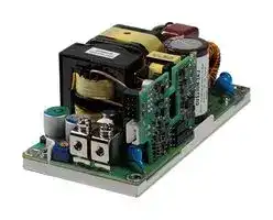


CUS250M-12
AC/DC Open Frame Power Supply (PSU), ITE, Household, Laboratory & Medical, 1 Output, 250W, 250 W
- Manufacturer: TDK-LAMBDA
- Product type: AC / DC Open Frame Power Supplies
- SVHC: No SVHC (15-Jan-2018)
- Product Range: CUS250M Series
- No. of Outputs: 1 Output
- Input Voltage VAC: 85V AC to 264V AC
- Power Supply Output Type: Adjustable, Fixed
- Output Current - Output 1: 20.83A
- Output Current - Output 2: -
- Output Current - Output 3: -
- Output Current - Output 4: -
- Output Voltage - Output 1: 12VDC
- Output Voltage - Output 2: -
- Output Voltage - Output 3: -
- Output Voltage - Output 4: -
- Power Supply Applications: ITE, Household, Laboratory & Medical
- Power Rating (Forced Cooling): 250W
- Power Rating (Convection Cooling): 250W
| Delivery and price | |
|---|---|
| Units per pack | 10 |
| Price | 97.61 € |
| Current stock | 10+ |
| Lead time | 30 days |
CUS250M Series

https://product.tdk.com/en/power/cus-m www.emea.lambda.tdk.com/cus250m

## 2 x 4” 250W AC-DC Power Supplies

The compact CUS250M is packaged in the industry standard 2x4” footprint.  The series can deliver 250W with forced air or conduction cooling in ambient temperatures of up to 45°C.  With Medical & ITE certifications, the unit can be used in both Class I & Class II (no ground wire) applications, and meets Class B Conducted and Radiated EMI with generous margins. Input voltage range includes operation down to 80Vac (see instruction manual for ratings). Other options include a 5V standby voltage, remote on/off, DC_OK and AC_Fail signals, with a U channel, cover or top fan mechanical construction.

|**Features**|**Benefits**|
|---|---|
|• Up to 250W Utilizing Convection and Conduction Cooling|• Quiet Operation|
|• Operation in Ambient Temperatures of up to 85oC|• Suitable for High Ambient Temperature Environments|
|• Medical Certifications (2 x MOPP)|• Suitable for B and BF Type Medical Equipment|
|• Class B Conducted and Radiated EMI with Significant Margins|• Easier System EMC Compliance|
|• Certified for Class I and Class II installations|• Flexible Utilisation|
|• Compact 2 x 4 x 1.56” / 50.8 x 101.6 x 39.5mm Size|• Space Saving in End Equipment|
|• Enclosure & Cooling Options|• Versatile Application|
|• EN60335-1 Compliant|• Suitable for Household and Similar Electrical Appliances|


## **Model Selector**

|Nominal Output|Nominal Output|Nominal Output||||Output|||Fan|Fan||Maximum Current|Maximum Current|Maximum Current|Maximum Current|Maximum Current|Maximum Current|Maximum Power|Maximum Power|Maximum Power|Maximum Power|
|---|---|---|---|---|---|---|---|---|---|---|---|---|---|---|---|---|---|---|---|---|---|
|Model|Voltage||||Adjustment(1)||||Supply||||Forced Air|||||Forced Air||Forced Air||
||(V)|||||(V)|||(V)|(V)|||(A)|||||(W)||||
|CUS250M-12|12||||12 - 13.2||||11.4||||20.83|||||250||||
|CUS250M-15|15||||15 - 16.5||||11.4||||16.66|||||250||||
|CUS250M-18|18||||18 - 19.8||||11.4||||13.88|||||250||||
|CUS250M-24|24||||24 - 26.4||||11.4||||10.41|||||250||||
|CUS250M-28|28||||28 - 30.8||||11.4||||8.92|||||250||||
|CUS250M-36|36||||36 - 39.6||||11.4||||6.94|||||250||||
|CUS250M-48|48||||48 - 52.8||||11.4||||5.2|||||250||||
|||||||||||||||||||||||
|**CUS250M-**|**12**||||**/**||**U**||||**M**|||||**-**||||**J**||
|||||||||||||||||||||||
|Output voltage 12, 15, 18, 24, 28, 36, 48||Output voltage 12, 15, 18, 24, 28, 36, 48|||||||blank JST connectors|blank JST connectors||||||||||||
||||||||||M(2)Molex type input connectors|Molex type input connectors|||Molex type input connectors|||||||||
|||||||||||||||||||||||
|||||blank||Open frame (with integral baseplate)|||||||blank Dual fuses|blank Dual fuses|blank Dual fuses|||||||
|||||U||U channel|||||||E(2)|Single input fuse in line||||||||
|||||A||U channel with cover||||||||||||||||
|||||F||U channel, cover and top mounted fan||||||||||blank||No options||||
|||||C||M3 inserts for underside mounting||||||||||G||5V 0.1A standby supply,||||
|||||||||||||||||||remote on/off (enable),||||
|Notes:<br>See website for detailed specifications, test methods and installation manual.<br>Specification parameters apply at 25oC ambient temperature unless otherwise stated.||||||||||||||||J|J|DC_OK, AC_Fail<br>5V 0.1A standby supply,||||
|(1) Output voltage is user adjustable or can be factory set.<br>Non-standard output versions may be subject to minimum order quantities and variations to specification.<br>For all non-standard output voltage settings please consult Sales.||||||Non-standard output versions may be subject to minimum order quantities and variations to specification.||||||||||||remote on/off (inhibit),<br>DC_OK, AC_Fail||||


Non-standard output versions may be subject to minimum order quantities and variations to specification. For all non-standard output voltage settings please consult Sales.

(2) Subject to Minimum Order Quantities. Please contact Sales

CUS250M Series

1

**==> picture [517 x 34] intentionally omitted <==**

|**Specifcations**|**Specifcations**|**Specifcations**|
|---|---|---|
|Model<br>CUS250M|||
|**Input**|||
|Input Voltage Range (Operating)|Vac|80 - 264(3)<br>|
|Nominal Input Voltage Range|Vac|100 - 240 (Note: Safety certifed for 80-264Vac)|
|Input Frequency|Hz|47 -  63(4)|
|Input Current (100Vac)|A|3.1<br>|
|Inrush Current at 230Vac (Cold Start)|A|<75. Note: the inrush I2t is signifcantly below the rating of the internal 5A fast acting fuse, or an external circuit breaker|
|Leakage Current|uA|<150 at 264Vac 63Hz|
|Touch Current (Enclosure Leakage)|uA|Class I: <10, Class II: <70, at 264Vac 63Hz|
|Power Factor (115/230Vac)|-|>0.9 / >0.7 (>20% load)|
|Harmonic Compliance|-|Meets IEC61000-3-2 Class A|
|No Load Power Consumption|W|<0.5 (230Vac) when output is inhibited|
|Hold Up Time<br>|ms|>14|
|Effciency<br>|%|Up to 94|
|Average Effciency|%|>91 Measured at 25%, 50%, 75% and 100% load conditions|
|Conducted & Radiated EMI|-|EN55032 / EN55011-B (See application notes for conditions)|
|Immunity|-|Designed to meet IEC60601-1-2 Ed.4.1, see immunity table|
|Insulation Class<br>|-|Construction suitable for Class I or Class II installation|
|Safety Certifcations and Markings|-|IEC/ES/EN60601-1 and IEC/UL/EN62368-1.IEC/EN61010-1 (5).<br>Compliant to IEC/EN60335-1 (6), CE Mark and UKCA Mark|


Notes:

(3) Derate output power linearly by 1%/Vac to 225W load from 100 to 90Vac input. Output power is reduced by 2%/Vac between 90Vac and 80Vac (180W at 80Vac)

(4) For operation at 440Hz please consult Technical Sales.

(5) For product labelled on or after 20th December 2024

(6) For 15V, 18V, 28V, 36V & 48V output product labelled on or after 15th January 2025. (12V and 24V models have been compliant since August 2022

CUS250M Series

2

**==> picture [516 x 34] intentionally omitted <==**

|<br> <br> <br> <br>**Immunity**|<br> <br> <br> <br>**Immunity**|<br> <br> <br> <br>**Immunity**|<br> <br> <br> <br>**Immunity**|
|---|---|---|---|
|Test<br>IEC61000-4-2 (ESD)|Test<br>Enclosure Port<br>AC Port<br>CH1 and Standby<br>Signal I/O Port (Remote On/Off, AC_FAIL, DC_OK)|UOM<br>Lvl<br>Lvl<br>Lvl<br>Lvl|Level & Criteria<br>Level 4, Criteria A<br>Level 4, Criteria A<br>Level 3, Criteria A<br>Level 3, Criteria A|
|IEC61000-4-3<br>(Radiated Immunity)|80 MHz to 2.7 GHz<br>2.7 GHz to 6 GHz|V/m<br>V/m|10 (Level 3, Criteria A)<br>10 (Level 3, Criteria A)|
|EN 60601-1-2:2015<br>(Radiated Immunity)|Immunity to RF Wireless Communications Equipment<br>(Table 9)|-|All Criteria, Criteria A|
|CISPR 35|1.8 GHz to 5 GHz|V/m|3 (Table 1, condition 1.3 requirements, Criteria A)|
|IEC 61204-3: 2000|900 MHz (Keyed Carrier)|V/m|3 (Criteria A)|
|IEC61000-4-4|AC Port|kV|4 (Level 4, Criteria A)|
|(Electrical Fast Transient Burst)|CH1<br>Fan Out, Standby<br>Signal I/O Port (Remote On/Off, AC_FAIL, DC_OK)|kV<br>kV<br>kV|2 (Level 4, Criteria A)<br>N/A<br>2 (Level 4, Criteria A)|
|IEC61000-4-5 (Surge)|(AC input common mode)<br>(AC input normal mode)|kV<br>kV|2 (Level 3, Criteria A)<br>1 (Level 3, Criteria A)|
|IEC61000-4-6<br>(Conducted Susceptibility)|(AC input common mode)<br>(DC output common mode)<br>(Fan Out, Standby common mode)<br>(Signal I/O common mode)|V<br>V<br>V<br>V|10 (Level 3, Criteria A)<br>10 (Level 3, Criteria A)<br>N/A<br>N/A|
|IEC61000-4-8<br> (Power Frequency Mag. Field)||A/m|(Level 4, Criteria A)|
|IEC61000-4-11<br>(Voltage dips / Interruption)|When exited factory (Bulk cap life degradation not considered)<br>0% for 0.5 cycle<br>0% for 1 cycle<br>40% for 10/12 cycles<br>70% for 25/30 cycles<br>80% for 250/300 cycles|-<br>Criteria<br>Criteria<br>Criteria<br>Criteria<br>Criteria|Class 3<br>A<br>A ≤175W, B >175W<br>100Vac: A≤50W, B>50W; 220Vac: A<br>100Vac: A≤150W, B>150W; 220Vac: A<br>100Vac: A≤200W, B>200W; 220Vac: A|
|IEC60601-1-2<br>(Voltage dips / Interruption)|0% for 250/300 cycles<br>When exited factory (Bulk cap life degradation not considered)<br>0% for 0.5 cycle<br>0% for 1 cycle<br>70% for 25/30 cycles|Criteria<br>-<br>Criteria<br>Criteria<br>Criteria|B<br>-<br>A<br>A ≤175W, B >175W<br>100Vac: A≤150W, B>150W; 220Vac: A|
|IEC61000-6-2<br>(Voltage dips / Interruption)|0% for 250/300 cycles<br>0% for 1 cycle<br>40% for 10/12 cycles<br>70% for 25/30 cycles|Criteria<br>Criteria<br>Criteria<br>Criteria|B<br>B<br>C<br>C|
|IEC61204-3<br>(Voltage dips / Interruption)|0% for 250/300 cycles<br>30% for 10 ms<br>60% for 100 ms|Criteria<br>Criteria<br>Criteria|C<br>B<br>100Vac: A≤70W, B>70W; 220Vac: A|
|SEMI F47|95% for 5000 ms<br>50% for 0.2 s<br>70% for 0.5 s<br>80% for 1s|Criteria<br>Criteria<br>Criteria<br>Criteria|C<br>170Vac: A≤240W, B>240W; 220Vac: A<br>A<br>A|
|IEC61000-4-12 (Ringwave Test)||-|(Level 3, Criteria A)|
|EN61000-4-14 (Voltage Fluctuations)||-|Class 3, Criteria A|


CUS250M Series

3

**==> picture [516 x 34] intentionally omitted <==**

|**Specifcations**|**Specifcations**|**Specifcations**||
|---|---|---|---|
|Model<br>CUS250M||||
|**Output**<br>||||
|Switching Frequency|kHz|Variable frequency from 25 to 300 (excluding burst mode) for the PFC, DC-DC and fyback converters.<br>Frequencies vary with input voltage, output voltage and output load.||
|Line Regulation|%|<0.5 (85 - 264Vac)||
|Load Regulation|%|<1 (0 - 100% load)||
|External Load Capacitance|uF|12V: 20,830, 15V: 16,660, 18V: 9,440, 24V: 2,290, 28V: 4,460, 36V: 3,470, 48V: 1,300||
|Ripple & Noise<br>|%|<1 of nominal output for operating temperatures above 0°C<br>12V model: <2, other voltages: <1.5 at -20°C. <2 in burst mode when the load is <10% of the rated current<br>External load capacitance will reduce the amplitude.||
|Temperature Coeffcient|%/°C|±0.02||
|Minimum Load|-|No minimum load required||
|Overcurrent Protection|%|110 to 170. Hiccup mode, automatic recovery||
|Overvoltage Protection|-|115-140% of standard output voltage<br>Latching (unit shutdown), cycle AC input or use remote on/off to reset||
|Overtemperature Protection|-|Latching, cycle AC or use remote on/off to reset||
|Remote Sense|-|None||
|Remote On/Off (Optional)|-|Opto-isolated. Inhibit: High = OFF, Low = ON, Enable: High = ON, Low = OFF||
|Standby Voltage (Optional)|-|5V 0.1A||
|Fan Supply (Standard)|-|11.4V 0.5A||
|DC_OK Signal (Optional)|-|Opto-isolated signal, transisitor is on when main output is good||
|AC_Fail signal (Optional)|-|Opto-isolated signal, transisitor is on when AC input is good||
|Parallel Operation|-|Not possible||
|Series Operation|-|Not possible||
|**Environmental**||||
|Operating Temperature (-40°C start-up)|°C|-20 to +85 with system forced air cooling (70 maximum for fan version /F), see derating curves below||
|Storage Temperature|°C|-40 to +85 (70 maximum for fan version /F)||
|Operating Humidity (non condensing)|%RH|5 - 95 (15 - 90 for /F fan version)||
|Pollution Degree|-|PD2 Material group IIIb||
|Cooling|-|Convection, conduction or forced air cooling. See derating curves below||
|Altitude|m|5,000||
|Withstand Voltage (For 1 minute)|Vac|Input to Ground 1,500 (1xMOPP), Input to Output 4,000 (2xMOPP), Output to Ground 1,500 (1xMOPP)||
|Isolation Resistance|MΩ|>100 at 25°C, 70%RH & 500VDC||
|Vibration (non operating)|-|2G, 10-500Hz for 1 hour||
|Shock (non operating)|-|30G, 11ms half sine||
|**Other**||||
|Weight|g|Open frame: 275, /A: 320,  /C: 275, /F: 345, /U: 305||
|Size (WxLxH)|mm|Open frame : 50.8 x 101.6 x 39.5<br>U channel : 64 x 119.2 x 39.5<br>Cover (/A) : 64 x 119.2 x 43<br>Fan (/F) : 64 x 119.2 x 60.6||
|Size (WxLxH)|Inches|Open frame: 2 x 4 x 1.56<br>U  channel : 2.52 x 4.69 x 1.56<br>Cover (/A) : 2.52 x 4.69 x 1.69<br>Fan (/F)  : 2.52 x 4.69 x 2.39||
|Connectors|-|Input: JST B2P3-VH, Output: M3 screw, Fan: Molex 22-05-7025, Signals: Molex 87833-0833||
|Warranty|yrs|5||


CUS250M Series

4

## **Peak Power Rating Curves**

## **U chassis configuration, convection cooled on metal baseplate**

Examples: 150W continuous - 250W peak - 1 min pulse time - 10% duty cycle 75W continuous - 250W peak - 2 mins pulse time - 10% duty cycle

## **Peak Power Rating Curves**

**Open frame configuration, convection cooled (no metal baseplate)**

**==> picture [170 x 28] intentionally omitted <==**

**----- Start of picture text -----**<br>
Examples:<br>150W continuous - 250W peak - 2 mins pulse time - 10% duty cycle<br>100W continuous - 250W peak - 5 mins pulse time - 10% duty cycle<br>25W continuous - 250W peak - 10 mins pulse time - 10% duty cycle<br>**----- End of picture text -----**<br>


## **Orientation**

## **Horizontal Orientation A**

## **Vertical Orientation B**

Notes: See website for detailed specifications, test methods and installation manual. Specification parameters apply at 25°C ambient temperature unless otherwise stated.

## **Output Power vs Ambient Temperature**

## **Conduction/convection cooled CUS250M-12**

## **Output Power vs Ambient Temperature**

## **Conduction/convection cooled CUS250M-24**

CUS250M Series

5

## **Output Power vs Ambient Temperature (forced air cooled) all CUS250M voltages**

## **Standby and Fan Output Power vs Ambient Temperature**

Notes

- 1:  Orientation A (see Application Note), 50mm above surface.

   - Standby output is loaded (see derating curves for Standby output), no load on Fan output

- 2: 50mm above surface. Limited by fan specification to 70°C maximum

- 3:  Tested with U chassis with airflow direction 1 (see Application Note).

   - Customer to ensure airflow rate and direction to keep components temperature below the limits.

   - Standby and Fan output load according to derating curves.

   - Measured in wind tunnel with 5mm space on side of U chassis.

- 4:  Mounted on natural aluminium plate, 300x300x1mm lifted 50mm above other surfaces Orientation A (see Application Note)

   - Standby output is loaded (see derating curves for Standby output), no load on Fan output

CUS250M Series

6

## **Outline Drawing CUS250M Open Frame Unit (Integral baseplate)**

**Outline Drawing CUS250M/C Open Frame Unit with inserts (Integral baseplate)**

**==> picture [358 x 251] intentionally omitted <==**

**----- Start of picture text -----**<br>
 3.18 ±0.20   95.25 ±0.20<br>A<br>A<br>A A<br>NOTE:<br>1. "A" FIXING HOLES WITH M3 INSERTS<br>2. ALL UNSTATED TOLERANCES ±  0.4mm<br> 44.45 ±0.22<br> 3.18 ±0.20<br>**----- End of picture text -----**<br>


CUS250M Series

7

## **Outline Drawing CUS250M/U (U Channel) Option**

## **Outline Drawing CUS250M/A (U Channel with Cover) Option**

**==> picture [455 x 270] intentionally omitted <==**

**----- Start of picture text -----**<br>
 31.48<br> 119.20 ±0.40<br> 102.70  DEFAULT SCREW   20.98<br>LOCATION<br>UNMASKED<br>SLOT UNMASKED<br>s ROODOOOOD. EE= \é SLOT j TOGestera0 OGr|<br>CO OOOSseodgngTgGSCOC HS[S] ea fo<br>ODOOGOT GOGGO et JOWe<br>CO OOGCGodoGGS |&4 oo ke<br>5OO O OH. GOGCO Bl loeoen|<br>| (|PES esl BPRSSeése6c06s SOOaaTCody<br> 24.40   15.38<br>ce  105.10  —<br> 3.50 ±0.20   112 ±0.20<br>jp<br>B B<br>"hE anne i<br>B B<br>_l L, = @) © G<br> 11.88 ±0.20   95.24 ±0.20<br>_<br>NOTE:<br>1. "B" HOLES 4 X M3 FIXING . MAX PENETRATION 3.75mm. RECOMMENDED TORQUE  0.5-0.6Nm<br>2. ALL UNSTATED TOLERANCES ±  0.4mm<br> R1.75TYP<br> 41.20   50.10   50.80   64 ±0.40<br> 31.70<br> 12.30<br> 35 ±0.20<br> 43 max.   44.45 ±0.20<br> 9.68 ±0.20<br> 14.40 ±0.20<br>**----- End of picture text -----**<br>


CUS250M Series

8

**==> picture [516 x 34] intentionally omitted <==**

## **Outline Drawing CUS250M/F (U Channel with Cover & Top Mounted Fan) Option**

**==> picture [511 x 315] intentionally omitted <==**

**----- Start of picture text -----**<br>
 31.48<br> 119.20 ±0.40<br> 102.70   20.98<br>DEFAULT SCREW<br>LOCATION<br>UNMASKED<br>SLOT UNMASKED<br>SLOT<br> 24.40   15.38<br> 105.10<br>DIRECTION OF AIRFLOW  3.50 ±0.20   112 ±0.20<br>�<br>B B<br>B B<br> 11.88 ±0.20   95.24 ±0.20<br>NOTE:<br>1. "B" HOLES 4 X M3 FIXING . MAX PENETRATION 3.75mm. RECOMMENDED TORQUE  0.5-0.6Nm<br>2. ALL UNSTATED TOLERANCES ±  0.4mm<br> R1.75TYP<br> 41.20   50.10   50.80   64 ±0.40<br> 31.70<br> 12.30<br> 59 max.<br> 35 ±0.20<br> 44.45 ±0.20<br> 9.68 ±0.20<br> 14.40 ±0.20<br>**----- End of picture text -----**<br>


CUS250M Series

9

## **TDK-Lambda France SAS**

Tel: +33 1 60 12 71 65 tlf.fr-powersolutions@tdk.com www.emea.lambda.tdk.com/fr

## **TDK-Lambda Americas**

Tel:  +1 800-LAMBDA-4 or 1-800-526-2324 tla.powersolutions@tdk.com www.us.lambda.tdk.com

## **Italy Sales Office**

Tel: +39 02 61 29 38 63 tlf.it-powersolutions@tdk.com www.emea.lambda.tdk.com/it

## **Netherlands**

## **TDK Electronics do Brasil Ltda**

Tel: +55 11 3289-9599 sales.br@tdk-electronics.tdk.com www.tdk-electronics.tdk.com/en

tlf.nl-powersolutions@tdk.com www.emea.lambda.tdk.com/nl

## **TDK-Lambda Germany GmbH**

Tel: +49 7841 666 0 tlg.powersolutions@tdk.com www.emea.lambda.tdk.com/de

## **TDK-Lambda Corporation**

Tel: +81-3-6778-1113 www.jp.lambda.tdk.com

## **TDK-Lambda (China) Electronics Co. Ltd.**

Tel: +86 21 6485-0777 tlc.powersolutions@tdk.com www.lambda.tdk.com.cn

**Austria Sales Office** Tel: +43 2256 655 84 tlg.at-powersolutions@tdk.com www.emea.lambda.tdk.com/at

## **Switzerland Sales Office**

Tel: +41 44 850 53 53 tlg.ch-powersolutions@tdk.com www.emea.lambda.tdk.com/ch

## **Nordic Sales Office**

## **TDK-Lambda Singapore Pte Ltd.**

Tel: +65 6251 7211 tls.marketing@tdk.com www.sg.lambda.tdk.com

**TDK India Private Limited, Power Supply Division** Tel:   +91 80 4039-0660 mathew.philip@tdk.com www.sg.lambda.tdk.com

Tel: +45 8853 8086 tlg.dk-powersolutions@tdk.com www.emea.lambda.tdk.com/dk

## **TDK-Lambda UK Ltd.**

Tel: +44 (0) 12 71 85 66 66 tlu.powersolutions@tdk.com www.emea.lambda.tdk.com/uk

## **TDK-Lambda Ltd.**

Tel: +9 723 902 4333 tli.powersolutions@tdk.com www.emea.lambda.tdk.com/il-en

For Additional Information, please visit https://product.tdk.com/en/power/

CUS250M_Datasheet 260897, February 3rd 2025 V10

CUS250M Series

10
Updated at April 27, 2026
TDK-Lambda is globally recognized as a premier manufacturer of highly reliable power supply solutions and power management equipment. With a strong engineering heritage, the company is a trusted partner for mission-critical applications across the industrial, medical, telecommunications, and test and measurement sectors, delivering components that meet stringent international performance and safety standards. Our extensive portfolio of TDK-Lambda products is heavily focused on comprehensive power and line protection, highlighted by a vast selection of industry-leading AC/DC converters. Engineered to deliver exceptional efficiency and stable performance in demanding environments, these power supplies form the backbone of our offering and are built to support the rigorous power demands of modern electronic infrastructure. To complement these primary power solutions, we also offer a targeted range of high-performance DC/DC converters designed for precise, board-level voltage regulation. Furthermore, to ensure the optimal performance and longevity of these power systems, our catalog includes specialized cooling and thermal management components, such as natural convection heat sinks, providing complete thermal stability for your most critical designs.
About Novapart
Novapart is a B2B electronic component broker specialising in stock shortages and cost reduction. We source hard-to-find parts and identify compliant alternatives across a catalogue of 410,000+ components from 500+ manufacturers.
Learn more →Stock Shortage Specialist
When a component is unavailable, discontinued or has an unacceptable lead time, we tap into our network of vetted European and Asian distributors to source what you need — without compromising on quality or traceability.
Request a quote →Compliant Alternatives
We identify pin-to-pin, electrically equivalent substitutes that meet the same certifications (RoHS, AEC-Q100, REACH) as your original specification — validated against datasheets, not just part numbers. Often at a lower cost.
BOM Analysis service →