
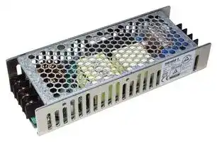


CUS-200LD-24
AC/DC Enclosed Power Supply (PSU), ITE, 1 Outputs, 120 W, 24 VDC, 5 A
- Manufacturer: TDK-LAMBDA
- Product type: AC / DC Enclosed Power Supplies
- No. of Outputs:1Outputs; Output Power Max:120W; Output Voltage - Output 1:24V; Output Current - Output 1:5A; Output Voltage - Output 2:-; Output Current - Output 2:-; Output Voltage - Output
- SVHC: No SVHC (15-Jan-2018)
- Product Range: CUS200LD Series
- No. of Outputs: 1Outputs
- Output Power Max: 120W
- Current, Output 4: -
- Input Voltage VAC: 85V AC to 265V AC
- Input Voltage AC Max: 265V
- Input Voltage AC Min: 85V
- Power Supply Output Type: Adjustable, Fixed
- Output Current - Output 1: 5A
- Output Current - Output 2: -
- Output Current - Output 3: -
- Output Voltage - Output 1: 24VDC
- Output Voltage - Output 2: -
- Output Voltage - Output 3: -
- Output Voltage - Output 4: -
- Power Supply Applications: ITE
| Delivery and price | |
|---|---|
| Units per pack | 50 |
| Price | 68.3 € |
| Current stock | 10+ |
| Lead time | 30 days |
**TDK-Lambda**

**CUS200LD**

## SPECIFICATIONS

## CA850-01-01C

||MODEL<br>ITEMS|MODEL<br>ITEMS|CUS200<br>LD-3|CUS200<br>LD-4|CUS200<br>LD-5|LD-7R5<br>CUS200|LD-12<br>CUS200|LD-15<br>CUS200|CUS200<br>LD-24|CUS200<br>LD-28|CUS200<br>LD-48|
|---|---|---|---|---|---|---|---|---|---|---|---|
|1|Nominal Output Voltage|V|3.3|4.2|5|7.5|12|15|24|28|48|
|2|Maximum Output Current@Convection cooling|A|24|24|24|16|10|8|5|4.3|2.5|
||Maximum Output Current@Conduction cooling (*12)|A|30|30|30|20|12.5|10|6.3|5.4|3.15|
||Peak Output Current<br>(*13)|A|40|40|40|26.6|16.7|13.4|8.4|7.2|4.2|
|3|Maximum Output Power@Convection cooling|W|79.2|100.8|120.0|120.0|120.0|120.0|120.0|120.4|120.0|
||Maximum Output Power@Conduction cooling (*12)|W|99.0|126.0|150.0|150.0|150.0|150.0|151.2|151.2|151.2|
||Peak Output Power<br>(*13)|W|132.0|168.0|200.0|199.5|200.4|201.0|201.6|201.6|201.6|
|4|Efficiency @Convection cooling (Typ.) 115/230 VAC(*1)|%|82/83|85/87|87/89|87/90|86/89|86/89|86/89|86/89|87/89|
||Efficiency @Conduction cooling (Typ.) 115/230 VAC(*1)|%|82/83|85/87|87/89|88/90|87/89|87/89|87/89|87/90|88/90|
|5|Input Voltage Range<br>(*2)|-|85 - 265 VAC(47-63Hz)|||||||||
|6|Input Current@Convection cooling (Typ.) 115/230 VAC(*1)|A|0.9 / 0.5|1.1 / 0.6|1.3 / 0.7|||||||
||Input Current@Conduction cooling (Typ.) 115/230 VAC(*1)|A|1.1 / 0.6|1.4 / 0.7|1.6 / 0.8|||||||
|7|In-rush Current (Typ.)<br>(*1)(*3)|A|20 / 40 at Cold Start|||||||||
|8|PFHC|-|Designed to meet IEC61000-3-2|||||||||
|9|Power Factor  (Typ.)<br>115/230 VAC(*1)|-|0.95 / 0.85|0.95 / 0.88|0.95 / 0.90|||||||
|10|Output Voltage Range|%|+10 / -10|+10 / -10|+10 / -10|+10 / -15|+10 / -10|+10 / -10|+10 / -10|+10 / -10|+10 / -10|
|11|Maximum Ripple & Noise<br>(*1)(*4)(*5)|mV|120|120|120|120|150|150|150|200|200|
|12|Maximum Line Regulation<br>(*4)(*6)|mV|13|16|20|30|48|60|96|112|192|
|13|Maximum Load Regulation<br>(*4)(*7)|mV|26|33|40|60|96|120|192|224|384|
|14|Temperature Coefficient<br>(*4)|-|Less than 0.02% / °C|||||||||
|15|Over Current Protection<br>(*8)|A|> 40.40|> 40.40|> 40.40|> 26.87|> 16.87|> 13.54|> 8.49|> 7.28|> 4.25|
|16|Over Voltage Protection<br>(*9)|V|3.80 -<br>5.44|4.83 -<br>6.51|7.50<br>5.75 -|8.63 -<br>10.87|17.40<br>13.80 -|21.75<br>17.25 -|27.60 -<br>34.80|40.60<br>32.20 -|55.20 -<br>69.60|
|17|Hold-up time (Typ.)<br>(*1)|ms|20|||||||||
|18|Leakage Current<br>(*10)|-|0.75mA max|||||||||
|19|Parallel Operation|-|No|||||||||
|20|Series Operation|-|Possible|||||||||
|21|Operating Temperature<br>(*11)|-|-25°C ~ +70°C,start upat -40°C|||||||||
|22|Operating Humidity|-|10 - 95%RH(No condensing)|||||||||
|23|Storage Temperature|-|-40°C ~ +85°C|||||||||
|24|Storage Humidity|-|10 - 95%RH(No condensing)|||||||||
|25|Cooling<br>(*12)|-|Convection or Conduction Cooling|||||||||
|26|Withstand Voltage|-|Input-FG : 2kVAC (20mA), Input-Output : 3kVAC (20mA),<br>Output-FG : 500VAC(100mA)|||||||||
|27|Isolation Resistance|-|More than 100MΩ at 25°C,70%RH,Output - FG : 500VDC|||||||||
|28|Vibration|-|At no operating, 10-55Hz (Sweep for 1min.)<br>Maximum 19.6m/s2X,Y,Z 1 hour each|||||||||
|29|Shock|-|Less than 196m/s2|||||||||
|30|Safety|-|Approved byIEC/UL/CSA/EN 62368-1,Designed to meet GB4943.1|||||||||
|31|EMI<br>(*1)|-|Designed to meet EN55011-B,EN55032-B,FCC-Class B|||||||||
|32|Immunity|-|Designed to meet IEC61000-4-2 (Level 2,3), IEC61000-4-3 (Level 3),<br>IEC61000-4-4 (Level 3), IEC61000-4-5 (Level 3,4),<br>IEC61000-4-6 (Level 3), IEC61000-4-8 (Level 4), IEC61000-4-11|||||||||
|33|Weight(Typ.)|g|<br>430|||||||||
|34|Size(L x W x H)|mm|160  x  62  x  31(Refer to the Outline Drawing)|||||||||


*Read instruction manual carefully, before using the power supply unit. =NOTES=

|34 Size(L x W x H)<br>mm<br>*Read instruction manual carefully, before using the power supply unit.<br>=NOTES=<br>160  x  62  x  31(Refer to the Outline Dr|34 Size(L x W x H)<br>mm<br>*Read instruction manual carefully, before using the power supply unit.<br>=NOTES=<br>160  x  62  x  31(Refer to the Outline Dr|34 Size(L x W x H)<br>mm<br>*Read instruction manual carefully, before using the power supply unit.<br>=NOTES=<br>160  x  62  x  31(Refer to the Outline Dr|the Outline Dr|the Outline Dr|awing)|
|---|---|---|---|---|---|
|<br>*1. At 115VAC/230VAC, Ta=25°C, nominal output voltage and maximum output power.<br>*2. For cases where conformance to various safety specs (UL, CSA, EN) are required,<br>input voltage range will be 100 ~ 240VAC (50-60Hz).<br>Output derating required when Vin is less than 115VAC, refer output derating curve for details.<br>Avoid operating the unit out of the specified input voltage range.<br>*3. Not applicable for the in-rush current to noise filter for less than 0.2ms.<br>*4. Please refer to Fig. A for measurement of Vo, line and load regulation and ripple voltage.<br>*5. Ripple & noise are measured at 20MHz by using a 150mm twisted pair of load wires<br>terminated with a 0.1uF and 100uF capacitor.<br>*6. 85~265VAC, constant load.<br>*7. No load - full load, constant input voltage.<br>*8. Hiccup with automatic recovery.<br>Aid i   ld  h ii dii<br>Output Terminal<br>Measurement point for Vo Line/Loa<br>Measuremen<br>47μ<br>150mm<br>-V<br>+V<br>100u|||150mm||d Regulation<br>t point for Ripple and Noise<br>0.1μ<br>Fig.A<br>A|
||Output Terminal||Measuremen<br>47μ<br>-V<br>+V<br>100u||t point for Ripple and Noi<br>0.1μ<br>Fig.A<br>A|
||||-V|||
||||Mea|||
|||||||
|||||Line/Loa||


Avoid operating at over load or short circuit condition.

*9. OVP circuit shut down the output, manual reset (Re power on) to get output voltage.

- *10. Measured by the each measuring method of UL, CSA, and EN (at 60Hz), Ta=25°C.

- *11. Refer to output derating curve for details of output derating versus input voltage, ambient temperature and mounting method.

   - Load (%) is percent of maximum output power and maximum output current. Do not exceed its derating of maximum Load.

   - Maximum load start up at -40°C  is possible. However, it may not fulfill all the specifications.

- *12. For conduction cooling, Power supply should be mounted on an Aluminum plate or heat sink with bottom side of the chassis, recommended AL plate size is 400*400*2mm. Refer to the output derating curve for output derating vs. ambient temperature and base plate temperature.

- *13. Refer to the next pages CA850-01-03_ and CA850-01-04_ for peak load defination and conditions.

**TDK-Lambda**

**CUS200LD**

## OUTPUT DERATING

CA850-01-02A

## **OUTPUT DERATING VERSUS INPUT VOLTAGE**

Maximum output power and output current derating vs. input voltage

**==> picture [436 x 286] intentionally omitted <==**

**----- Start of picture text -----**<br>
CUS200LD-3 CUS200LD-4<br>Input Voltage (VAC) Load (%) Input Voltage (VAC) Load (%)<br>85~265 100 85 90<br>100~265 100<br>CUS200LD-5,-7R5,-12,-15,-24,-28,-48<br>Input Voltage (VAC) Load (%)<br>85 80<br>115~265 100<br>120<br>100<br>1 1 1 1 1 1 1 1<br>1 1 1 1 ! 1 1 1 1<br>1 1 1 1 1 1 1 1 1 1<br>80 Bsaas1Jo1 lnm1jon1 mn n=1j-----4-1 11eeeta---=t—11ted aed11 !L-----L-1 ed 1bennnnbn1 111 ----L-1Jenn nnn! m CUS200LD-3<br>1 1 1 1 1 1 1 1 1<br>1 1 1 1 1 1 1 1 1<br>1 1 1 ! 1 1 1 1<br>60 - ----+-11 -----—11-----4--! 11 ---4--4-----1-— 1 bannna1 b 1 -—annnnbmL-----1 1 L ----4---— ae CUS200LD-4<br>! 1 1 1 ! 1 1<br>1 1 1 1 1 1 1<br>1 1 ! ! i 1<br>40 iejenn ceed nn danmialetaiatsiaiaialioaeieien [iia] 1 [|] booeecbhanncee [nee] enaecae<br>1 1 1 1 1 1 1 1 1<br>!1 1! 1 I i1 !1 11 11 11 1! -—e CUS200LD-5,-7R5,<br>20 ____ ieiaiel -4_--.-1I -4_--.-}-4_----}-}_-_--}-L_----}--L----4+4-4---- - -12,-15,-24,-28,-48<br>leila 1 i 1 1 1 1 1 1 1<br>1 1 1 1 1 1 1 1 1 1 1<br>1 1 1 1 1 1 ! 1 1 1 1<br>1 1 1 1 1 1 1 1 1 1 1<br>0 1 1 i i 1 1 1 i i 1 1<br>85 100 115 130 145 160 175 190 205 220 235 250 265<br>Vin (VAC)<br>Load (%)<br>**----- End of picture text -----**<br>


**==> picture [493 x 27] intentionally omitted <==**

**----- Start of picture text -----**<br>
MOUNTING A MOUNTING B MOUNTING C MOUNTING D MOUNTING E<br>L<br>(STANDARD MOUNTING)<br>**----- End of picture text -----**<br>


**TDK-Lambda**

**CUS200LD**

OUTPUT DERATING

CA850-01-03

## **OUTPUT DERATING VERSUS  OPERATING AMBIENT TEMPERATURE (Ta)**

## **1. CONDUCTION COOLING**

**==> picture [493 x 273] intentionally omitted <==**

**----- Start of picture text -----**<br>
(1) Maximum output power and output current derating vs. ambient temperature and base plate temperature<br>Mounting A,B,C Mounting D,E<br>Ta (°C) Tb (°C) Load (%) Ta (°C) Tb (°C) Load (%)<br>-25 - +45 -25 - +75 100 -25 - +35 -25 - +65 100<br>+70 +90 40 +60 +80 40<br>120 120<br>100 100<br>A A<br>80 80<br>70 70<br>60 60<br>40 40<br>20 20<br>0 0<br>Ta ( [o] C) -30 -20 -10 0 10 20 30 40 50 60 70 80 Ta ( [o] C) -30 -20 -10 0 10 20 30 40 50 60 70 80<br>Tb ( [o] C) 75 90 Tb ( [o] C) 65 80<br>Ta: Ambient Temperature<br>Tb: Base plate temperature, measured at the center of the bottom side of the power supply chassis<br>      Please refer to the instruction manual for details.<br>Load (%) Load (%)<br>**----- End of picture text -----**<br>


Notes:

1. Maximum output power and output current must not exceed the derating curve of Ta and Tb. 2. Low Temperature Operation Area (A):

Output voltage may be fluctuated during start up or sudden change of load conditions in this area when input voltage is below 115VAC. Output voltage will be stable after power supply warm up, or the input voltage is higher than 115VAC. Please refer to the instruction manual for details.

## (2) Defination of peak load operation

Average current defination:

**==> picture [391 x 83] intentionally omitted <==**

**----- Start of picture text -----**<br>
Im Ip Iav     Ip :   Peak output current (A)<br>    Im :  Minimum output current (A)<br>0<br>τ     Iav : Average output current (A)<br>T     D :   Duty cycle, τ/T (%)<br>Iav =Ip  x  D + Im  x  (1-D)<br>**----- End of picture text -----**<br>


Notes:

1. Operating period at peak output current (τ) is less than 10 seconds, duty is less than 35%

2. Average output power and output current is less than the Maximun output power and output current.

3. Peak output power and output current derating vs. input voltage and ambient temperature is same as the derating of maximum output power and output current.

**TDK-Lambda**

**CUS200LD**

OUTPUT DERATING

CA850-01-04

## **2. CONVECTION COOLING**

**==> picture [480 x 483] intentionally omitted <==**

**----- Start of picture text -----**<br>
(1) Maximum output power and output current derating vs. ambient temperature<br>Mounting A Mounting B,C Mounting D,E<br>Ta (°C) Load (%) Ta (°C) Load (%) Ta (°C) Load (%)<br>-25 - +40 100 -25 - +35 100 -25 - +30 100<br>+70 40 +65 40 +60 40<br>120<br>100<br>A<br>85<br>80 Mounting A<br>60 Mounting B,C<br>40 Mounting D,E<br>20<br>0<br>-25-20-15-10 -5 0 5 10 15 20 25 30 35 40 45 50 55 60 65 70 75<br>Ta ( ° C)<br>Notes:<br>1. Maximum output power and output current must not exceed the derating curve of Ta<br>2. Low Temperature Operation Area (A):<br>Output voltage may be fluctuated during start up or sudden change of load conditions in this area when input voltage<br>is below 115VAC. Output voltage will be stable after power supply warm up, or the input voltage is higher than<br>115VAC. Please refer to the instruction manual for details.<br>(2) Defination of peak load operation<br>         Average output current defination:<br>Im Ip Iav     Ip :   Peak output current (A)<br>    Im :  Minimum output current (A)<br>0     Iav : Average output current (A)<br>τ<br>    D :   Duty cycle, τ/T (%)<br>T<br>Iav =Ip  x  D + Im  x  (1-D)<br>Notes:<br>Load (%)<br>**----- End of picture text -----**<br>


1. Operating period at peak output current (τ) is less than 5 seconds, duty is less than 35%.

2. Average output power and output current is less than the Maximun output power and output current.

3. Peak output power and output current derating vs. input voltage and ambient temperature is same as the derating of maximum output power and output current.
Updated at June 4, 2026
TDK-Lambda is globally recognized as a premier manufacturer of highly reliable power supply solutions and power management equipment. With a strong engineering heritage, the company is a trusted partner for mission-critical applications across the industrial, medical, telecommunications, and test and measurement sectors, delivering components that meet stringent international performance and safety standards. Our extensive portfolio of TDK-Lambda products is heavily focused on comprehensive power and line protection, highlighted by a vast selection of industry-leading AC/DC converters. Engineered to deliver exceptional efficiency and stable performance in demanding environments, these power supplies form the backbone of our offering and are built to support the rigorous power demands of modern electronic infrastructure. To complement these primary power solutions, we also offer a targeted range of high-performance DC/DC converters designed for precise, board-level voltage regulation. Furthermore, to ensure the optimal performance and longevity of these power systems, our catalog includes specialized cooling and thermal management components, such as natural convection heat sinks, providing complete thermal stability for your most critical designs.
About Novapart
Novapart is a B2B electronic component broker specialising in stock shortages and cost reduction. We source hard-to-find parts and identify compliant alternatives across a catalogue of 410,000+ components from 500+ manufacturers.
Learn more →Stock Shortage Specialist
When a component is unavailable, discontinued or has an unacceptable lead time, we tap into our network of vetted European and Asian distributors to source what you need — without compromising on quality or traceability.
Request a quote →Compliant Alternatives
We identify pin-to-pin, electrically equivalent substitutes that meet the same certifications (RoHS, AEC-Q100, REACH) as your original specification — validated against datasheets, not just part numbers. Often at a lower cost.
BOM Analysis service →