
Image not available
Illustrative purposes only

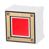
CTHS15CIC01
CAP-TOUCH SENSOR DISPLAY, 5.5V
⚠️ Reference pricing provided. In case of supply shortages, we will connect you with our trusted procurement partners to ensure your project's continuity.
- Manufacturer: VCC / VISUAL COMMUNICATIONS COMPANY
- Product type: Capacitive Proximity Sensors
- Sensor Output Type:-; Product Range:CTH Series; Sensing Range Max:0mm; Supply Voltage DC Max:5.5V; Supply Voltage DC Min:2V 06AC2653
- SVHC: No SVHC (21-Jan-2025)
- Display Type: LED
- Product Range: CTH Series
- Switch Terminals: -
- Pixel Size (H x W): -
- Sensor Output Type: -
- Backlighting Colour: Red
- Contact Current Max: -
- Contact Voltage VDC: -
- Sensing Distance Max: 0mm
- Viewing Area (H x W): -
- Contact Configuration: -
| Delivery and price | |
|---|---|
| Units per pack | 500 |
| Price | 3.18 € |
| Current stock | 10+ |
| Lead time | 30 days |
Datasheet

**==> picture [15 x 8] intentionally omitted <==**

**----- Start of picture text -----**<br>
TM<br>**----- End of picture text -----**<br>


## CTH Series

## Capacitive Touch Sensor Display 15.0 x 15.0 x 11.0 mm

**CTHS15CIC01 - Super Red Capacitive Touch Sensor Through Hole with a Display Size of 0.59 x 0.59 inches (15 x 15 mm) square**

## **Applications**

- **Mobile communication devices**

- **Electronic devices**

- **Point of sale Terminals**

- **Gaming**

   - **Touch Screen Monitors**

   - **Portable Instruments**

   - **Media Players**

   - **Medical devices**

- **Industrial control displays** • **Appliances and consumer equipments**

## **Key Features**

- **Integrated touch sensing and display technology**

- **Enables the device interface to be more user friendly and intuitive**

- **Mounting type: through hole (industry standard pitch 0.100”)**

- **Available in one standard size: 15.0mm x 15.00mm x 11.00mm**

- **Available in 5 colors: super red, white, pure green, blue or yellow**

- **Touch sensor: integrated circuit (IC)**

- **Uniform illumination and high optical clarity due to LED technology**

- **Robust design due to no mechanical moving parts**

- **Simplifies devices design and manufacturability**

- **Optional overlay (icons): on/off, arrow, alarm**

- **Custom overlay icon can be manufactured upon request - contact VCC**

- **Compliant with RoHS and REACH requirements**

the first call for illuminated components

www.vcclite.com

1.800.522.5546 11/16 Rev 1

1

## **Ordering Data**

**==> picture [475 x 281] intentionally omitted <==**

**----- Start of picture text -----**<br>
The CTH Series (Cap Touch) is available in a range of standard features and options.<br>To specify your Cap Touch Display, simply choose one option from each column.<br>Mounting<br>Series Type Shape Dimension Polarity IC Color Overlay*<br>C TH S 15 C IC<br>Cap Touch Integrated  ONOFF ON/OFF<br>Circuit ARROW Arrow<br>15 mm x<br>Through-Hole 15 mm ALARM Alarm<br>Square Common  Super Red 01<br>Cathode<br>SRN White 04<br>Pure Green 05<br>Blue 06<br>Yellow 07<br>== ==<br>*Optional<br>Overlay<br>•  Different LED colors can indicate the mode in which an electronic device is operating,<br>   depending on the icon associated with it.<br>**----- End of picture text -----**<br>


- Optional graphic overlay made with polished LEXAN™ Polycarbonate 8010 Film 0.007"

- (0.175 mm) thick has reverse printed translucent white icon, in order to still see it even when the back lighting is off.

- Lexan 8010 is a transparent polycarbonate film and offers hardness, chemical and abrasion resistance, stiffness, and high temperature capability.

- Three standard icons are available: alarm, arrow and on-off. Custom icons are also available upon request.

- Capacitive Touch Display can also be mounted behind clear glass or plastic layer such as polycarbonate or acrylic, as shown in the picture below.

Maximum thickness of acrylic/glass, 0.118” (3mm)

**==> picture [323 x 115] intentionally omitted <==**

**----- Start of picture text -----**<br>
Overlay On/Off<br>Maximum distance<br>between overlay<br>and acrylic/glass:<br>0.015” (0.38mm)<br>Overlay Arrow<br>Overlay Alarm<br>**----- End of picture text -----**<br>


the first call for illuminated components

www.vcclite.com

1.800.522.5546 11/16 Rev 1

2

## **Package Dimensions**

**==> picture [487 x 197] intentionally omitted <==**

**----- Start of picture text -----**<br>
MARKING<br>PIN 1 LABEL<br>0.610<br>[2.54]X3 = 7.62 0.024 (4 PL)<br>0.100X3 = 0.300<br>11.02 0.434 10.01 0.394<br>6.50 0.256<br>**----- End of picture text -----**<br>


**==> picture [269 x 201] intentionally omitted <==**

**----- Start of picture text -----**<br>
15.01<br>0.591<br>13.41<br>0.528<br>9.00<br>0.354<br>LUMINOUS<br>ZONE<br>TOUCH PAD<br>15.01  0.591<br>13.41 0.528 9.00 0.354<br>**----- End of picture text -----**<br>


## **MARKING LABEL INFO**

CTHS15CICXX XXXX    RoHS DATE CODE

**==> picture [109 x 63] intentionally omitted <==**

## Dimensions in [mm] inches General tolerances unless otherwise specified:

||inches|mm|
|---|---|---|
|.X|+<br>.020|+<br>.508|
|.XX|+<br>.010|+<br>.254|
|.XXX|+<br>.005|+<br>.127|


the first call for illuminated components

www.vcclite.com

1.800.522.5546

11/16 Rev 1

3

## **Internal Circuit Diagram**

**==> picture [549 x 256] intentionally omitted <==**

**----- Start of picture text -----**<br>
PIN 3<br>PIN 1<br>VCC 1 MCU 3<br>PIN 2<br>U1<br>1 4<br>Touch Pad OUT 2 OUT LOWP<br>2 5<br>VSS VDD<br>3 6 R1 C3<br>Touch Pad IN IN VSS<br>0/OPEN 0201<br>C4 0.1uF 0805 D6 D7<br><50pF/OPEN 0603<br>PIN 4<br>GND 4<br>**----- End of picture text -----**<br>


## **Internal IC Electrical Characteristics**

(TA = 25°C, unless otherwise specified)

|||(TA =25°|C, unle|ss othe|rwise spe|cified)|
|---|---|---|---|---|---|---|
|**Symbol**|**Parameter**|**Condition**|**Min.**|**Typ.**|**Max.**|**Units.**|
|VDD|Supply Voltage||2.0||5.5|V|
|VIH|High Level Input Voltage|@ VDD= 5V|0.7VDD||VDD|V|
|VIL|Low Level Input Voltage|@ VDD= 5V|||0.3VDD|V|
|IDD1|Operating Current|@ VDD= 5V , no load<br>@ VDD= 3V , no load<br>-----------------------------|---------|16<br>3.5<br>--------|-----------|μA|
|IDD2|Operating Current<br>( SLRT=VDD )|@ VDD= 5V , no load<br>@ VDD= 3V , no load<br>-----------------------------|---------|10.5<br>2.5<br>---------|----------|μA|
|IOL|Low Level Output Current|@ VDD= 3V, VOL= 1V||30||mA|
|IOH|High Level Output Current|@ VDD= 3V, VOL= 2V||8||mA|


the first call for illuminated components

www.vcclite.com

1.800.522.5546 11/16 Rev 1

4

## **Product Specifications**

## **ABSOLUTE MAXIMUM RATING FOR LED (Ta=25°C)**

|**r**<br>**e**<br>**t**<br>**e**<br>**m**<br>**a**<br>**r**<br>**a**<br>**P**|**l**<br>**o**<br>**b**<br>**m**<br>**y**<br>**S**|**g**<br>**n**<br>**it**<br>**a**<br>**R**|**ti**<br>**n**<br>**U**|
|---|---|---|---|
|||**Red**||
|Power Dissipation Per Dice|PAD|70|mW|
|Derating Liner from 25°C per Dice|-|0.33|mA/°C|
|Continuous Forward Current Per Dice|IAF|25|mA|
|Peak Current Per Dice<br>(duty cycle 1/10,1KHz)|IPF|90|mA|
|Reverse Voltage Per Dice|VR|5|V|
|Operating Temp.|Topr|-35 ~ +85|°C|
|Storage Temp.|Tstg|-35 ~ +85|°C|


## **ELECTRO-OPTICAL CHARACTERISTICS**

**(Ta=25°C)**

|**r**<br>**e**<br>**t**<br>**e**<br>**m**<br>**a**<br>**r**<br>**a**<br>**P**|**l**<br>**o**<br>**b**<br>**m**<br>**y**<br>**S**|**.**<br>**n**<br>**i**<br>**M**|**.**<br>**p**<br>**y**<br>**T**|**.**<br>**x**<br>**a**<br>**M**|**ti**<br>**n**<br>**U**|**n**<br>**o**<br>**iti**<br>**d**<br>**n**<br>**o**<br>**C**|
|---|---|---|---|---|---|---|
|Luminous Intensity|IV|17|31|--|mcd|IF= 20 mA|
|Forward Voltage|VF|--|2.0|2.8|V|IF= 20 mA|
|Peak Emission Wavelength|λP|--|660|--|nm|IF= 20 mA|
|Dominant Wavelength|λD|--|645|--|nm|IF= 20 mA|
|Spectrum Radiation Bandwidth|λ|--|20|--|nm|IF= 20 mA|
|Luminous Intensity Matching Ratio|<br>IV-M|--|-|2 : 1|--|IF= 10 mA|
|Reverse Current|IR||-|100|μA|VR= 5V|


the first call for illuminated components

www.vcclite.com

1.800.522.5546

11/16 Rev 1

5

## **Product Specifications**

## **ELECTRICAL/OPTICAL CHARACTERISTICES CURVES**

## **(Ta=25°C)**

30 25 20 15 10 5 0 0 1 2 3 4 Forward Voltage (V) **Forward Current vs. Forward Voltage**

**==> picture [189 x 143] intentionally omitted <==**

**----- Start of picture text -----**<br>
3.0<br>2.5<br>2.0<br>1.5<br>1.0<br>0.5<br>0.0<br>0 10 20 30<br>Forward Voltage (mA)<br>Relative Intensity vs. Forward Current<br>Relative Intensity<br>Normalize @10 ma<br>**----- End of picture text -----**<br>


**==> picture [178 x 125] intentionally omitted <==**

**----- Start of picture text -----**<br>
1.2<br>1.1<br>1.0<br>0.9<br>0.8<br>-40 -20 0 20 40 60 80 100<br>Ambient Temperature  (°C)<br>Forward Voltage vs. Temperature<br>Normalize @ 25°c<br>Forward Voltage @ 20 mA<br>**----- End of picture text -----**<br>


**==> picture [174 x 125] intentionally omitted <==**

**----- Start of picture text -----**<br>
1.0<br>0.5<br>0.0<br>400 450 500 550<br>wavelength λ (nm)<br>Relative Intensity vs. Wavelength<br>@ 20 mA<br>Relative  Intensity<br>**----- End of picture text -----**<br>


**==> picture [187 x 337] intentionally omitted <==**

**----- Start of picture text -----**<br>
3.0<br>2.5<br>2.0<br>1.5<br>1.0<br>0.5<br>0.0<br>-40 -20 0 20 40 60 80 100<br>Ambient Temperature  (°C)<br>Relative Intensity vs. Temperature<br>35<br>30<br>25<br>20<br>15<br>10<br>5<br>0<br>-40 -20 0 20 40 60 80 100<br>Ambient Temperature  (°C)<br>Forward Current vs. Temperature<br>Normalize @ 25°c<br>Relative Intensity @ 20 mA<br>Forward Current (mA)<br>**----- End of picture text -----**<br>


the first call for illuminated components

www.vcclite.com

1.800.522.5546

11/16 Rev 1

6

## **Product Specifications**

## **SOLDERING CONDITIONS**

## **1. Wave Soldering Profile**

Distance: 1.6mm min (From Seating Plane)

|**Item**|**Condition**|**Condition**|**Note**|
|---|---|---|---|
|Preheat|Temperature T1|80 – 120 °C|PWB Temperature<br>(Soldering Side Surface)|
||Time t1|60 – 180sec||
|Solder Dip|Temperature T2|230 – 260°C|Bath Temperature|
||Time t2|2 – 4 sec|Solder Tank Passage Time|


## Temp(°C )

**==> picture [354 x 180] intentionally omitted <==**

**----- Start of picture text -----**<br>
_  _ _ _ _ _ _ _ _ _ _ _ _ _ _ _ _ _ _ _ _ _<br>T2<br>_  _ _ _ _ _ _ _ _ _ _ _ _ _ _ _ _ _ _<br>T1<br>Preheat Solder dip<br>25<br>t1 Time(sec)<br>t2<br>**----- End of picture text -----**<br>


## **2. Hand Soldering (Iron Condition)**

Soldering Iron: 30W Max

Temperature 350°C Max

Soldering Time: 3 Seconds Max (One Time)

Distance: 1.6mm min (From Seating Plane)

the first call for illuminated components

www.vcclite.com

1.800.522.5546

11/16 Rev 1

7

## **Application Circuit**

**==> picture [519 x 307] intentionally omitted <==**

**----- Start of picture text -----**<br>
VDD<br>VDD<br>R1<br>INPUT OUTPUT PNP TRANSISTOR<br>R2<br>VSS<br>R3<br>CONTROLLER<br>CAP TOUCH SWITCH<br>INTERNAL<br>IC<br>VSS<br>- b a s<br>|<br>_<br>VDD OUT<br>PIN 1 PIN 2 PIN 3 PIN 4<br>**----- End of picture text -----**<br>


## **Compliances and Approvals**

the first call for illuminated components

www.vcclite.com

1.800.522.5546 11/16 Rev 1

8
Updated at June 3, 2026
About Novapart
Novapart is a B2B electronic component broker specialising in stock shortages and cost reduction. We source hard-to-find parts and identify compliant alternatives across a catalogue of 410,000+ components from 500+ manufacturers.
Learn more →Stock Shortage Specialist
When a component is unavailable, discontinued or has an unacceptable lead time, we tap into our network of vetted European and Asian distributors to source what you need — without compromising on quality or traceability.
Request a quote →Compliant Alternatives
We identify pin-to-pin, electrically equivalent substitutes that meet the same certifications (RoHS, AEC-Q100, REACH) as your original specification — validated against datasheets, not just part numbers. Often at a lower cost.
BOM Analysis service →