
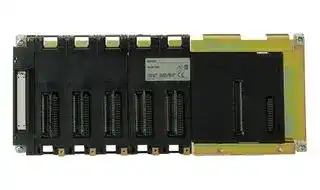


CS1D-BC052
Backplane, CS1 Series Controller
- Manufacturer: OMRON INDUSTRIAL AUTOMATION
- Product type: Controller Accessories
- SVHC: To Be Advised
| Delivery and price | |
|---|---|
| Units per pack | 1 |
| Price | 1210.17 € |
| Current stock | 10+ |
| Lead time | 30 days |
## **CS1D-CPU** @@

## **Duplex CPU units**

## **The CS1 Duplex System Boosts the Reliability of Facilities and Equipment**

## **Hot Standby System for CPU Unit Duplexing**

- When a problem occurs in the CPU Unit, the system instantly switches control to the other CPU Unit, enabling continuous operation with minimal effect on the system.

- Because there is no need for special duplex  programming, the design process is simple and design steps are reduced.

- **Note:** The system can also be configured with only one each of the CPU, Power Supply, and Communications Units. This lets you optimize the system cost by selecting the Units that you need. (The Duplex Unit must be used even when using only one each of the CPU, Power Supply, and Communications Units.)

## **Higher Network Reliability**

Duplex Communications Units and a loopback configuration enable continuous communications even in the event of a problem.

**==> picture [218 x 105] intentionally omitted <==**

**----- Start of picture text -----**<br>
Broken<br>line<br>Communications<br>line backup<br>by a loopback<br>configuration<br>Node backup<br>by Duplex<br>Communications<br>Unit<br>**----- End of picture text -----**<br>


**Note:** The CS1W-CLK12-V1 or CS1W-CLK52-V1 is required for network duplexing.

Duplex CPU Units for greater system reliability

Duplex Communications (Controller Link) Units for greater network reliability

**==> picture [212 x 20] intentionally omitted <==**

**----- Start of picture text -----**<br>
Duplex Power Supply Units protect<br>Duplex Unit<br>against power supply problems<br>**----- End of picture text -----**<br>


**Duplex CPU units**

267

## **With the Duplex PLC System, restoring the system is fast and easy.**

## **The CPU, Power Supply, or Communications Unit can be replaced while the system continues to operate.**

**==> picture [491 x 302] intentionally omitted <==**

**----- Start of picture text -----**<br>
On Operating<br>If the CPU Unit should stop due to malfunction, operation continues  Operating standby<br>with the other CPU Unit so you can replace the broken Unit without<br>even stopping the system. The same is possible for the Power Supply<br>and Communications Units.<br>Naturally, Basic and Special I/O Units can also be replaced. Units can be replaced,<br>With the CS1D, Basic I/O Units, Special I/O Units, and CPU Bus Units  and problems solved,<br>can all be replaced during operation. The Unit being replaced stops  without stopping thesystem.<br>operating during replacement, but all other Units continue to operate.<br>operatingStarts standbyOn Duplex<br>operation<br>resumes.<br>| A high-performance PLC with advanced functions to expand control possibilities.<br>High reliability, plus high performance. Of course, PLC functions have also been increased.<br>The CPU Units in this Duplex System feature both high performance  • Built-in Flash memory enables battery-less operation.<br>and advanced functions, providing high reliability even to applications  • Various self-diagnostic functions are included.<br>requiring high speed.<br>• A wide range of calculation functions includes floating point<br>calculations, character string processing, and PID calcula-<br>Approx. 50% tions with auto tuning.<br>(compared • Structured programming (multitask and variable program-<br>with previous ming supported)<br>OMRON<br>duplex<br>models)<br>Problem<br>occurs<br>**----- End of picture text -----**<br>


If the CPU Unit should stop due to malfunction, operation continues with the other CPU Unit so you can replace the broken Unit without even stopping the system. The same is possible for the Power Supply and Communications Units.

## **Naturally, Basic and Special I/O Units can also be replaced.**

With the CS1D, Basic I/O Units, Special I/O Units, and CPU Bus Units can all be replaced during operation. The Unit being replaced stops operating during replacement, but all other Units continue to operate.

## ~~|~~ **A high-performance PLC with advanced functions to expand control possibilities.**

**High reliability, plus high performance.** The CPU Units in this Duplex System feature both high performance and advanced functions, providing high reliability even to applications requiring high speed.

- A wide range of calculation functions includes floating point calculations, character string processing, and PID calculations with auto tuning.

## ~~|~~ **Installation costs and maintenance costs are reduced.**

**Allows effective use of software assets.** The same support software can be used in systems combining the CS1 and CJ1 Series, and all software programs and data are compatible. There is no need for ladder programs for duplexing. This means that when converting an existing system to a Duplex System, there is almost no need to revise ladder programs.

## **Complete compatibility among Units.**

The CS1D Duplex System is fully compatible with the I/O Units of the entire CS Series. The same Units and materials can be used for hardware replacement and system maintenance. There is no need to purchase different Units and materials for each system, making the CS1D Duplex System highly economical.

(The CS1D only supports the CS1 Series I/O Units, not the C200H series I/O units)

Programmable Controllers

268

## ~~P~~ **Dimensions** ~~O~~

|||||||Unit: mm<br>**Backplane**<br>CPU Backplanes|Unit: mm<br>**Backplane**<br>CPU Backplanes|**Model**<br>**A**<br>**W**<br>CS1W-BC023(2 slots)<br>172.3<br>198.5|
|---|---|---|---|---|---|---|---|---|
|||||||||CS1W-BC033(3 slots)<br>246<br>260|
|[——h|||—p—|||||CS1W-BC053(5 slots)<br>316<br>330<br>CS1W-BC083(8 slots)<br>421<br>435<br>CS1W-BC103(10 slots)<br>491<br>505<br>~~es~~|
|Unit: mm||||||||CS1D-BC052|
|**Backplanes**<br>**CPU Backplane with 2 Slots**<br>**Backplane**<br>**A**<br>**B**<br>CS1W-BC023(2 slots)<br>172.3<br>145<br>CS1W-BC033(3 slots)<br>246<br>118<br>CS1W-BC053(5 slots)<br>316<br>CS1W-BC083(8 slots)<br>421<br>CS1W-BC103(10 slots)<br>491<br>CS1D-BC052(Duplex System)<br>Four, M4<br>~~==~~||**W**<br>198.5<br>260<br>330<br>435<br>505|**H**<br>157<br>130|**D**<br>123<br>~~|~~|||(Duplex System)<br>CS1 Expansion<br>Backplanes<br>CS1W-BI033(3 slots)<br>246<br>260<br>CS1W-BI053(5 slots)<br>316<br>330<br>CS1W-BI083(8 slots)<br>421<br>435<br>CS1W-BI103(10 slots)<br>491<br>505<br>CS1D-BI092<br>(Duplex System)<br>C200H Expansion I/O<br>Backplanes<br>C200HW-BI031(3 slots)<br>175<br>189<br>C200HW-BI051(5 slots)<br>245<br>259<br>C200HW-BI081-V1<br>(8 slots)<br>350<br>364<br>C200HW-BI101-V1<br>(10 slots)<br>420<br>434<br>~~=~~<br>~~on~~<br>~~es~~<br>.<br>~~SeF=~~||


**==> picture [147 x 81] intentionally omitted <==**

**----- Start of picture text -----**<br>
Four, M4<br>CS1W-BC023<br>CPU Backplane 145±0.3<br>172.3±0.3<br>__ _<br>**----- End of picture text -----**<br>


## **Mounting Depth**

The depth of all Racks is from 118 to 153 mm depending on the Units that are mounted. Additional depth is required to connect Peripheral Devices and Cables. Be sure to allow sufficient mounting depth.

**Note:** Expansion Backplanes cannot be connected to 2-slot CPU Backplanes.

## **CPU Backplane with 3, 5, 8, or 10 Slots**

**==> picture [165 x 125] intentionally omitted <==**

**----- Start of picture text -----**<br>
Four, M4 A±0.3<br>130 CPU Backplane 118±0.3<br>68 min. 80<br>fp A± -S=4, 0.3 |<br>130 Expansion Backplane 118±0.3<br>Four, M4 a W<br>**----- End of picture text -----**<br>


**==> picture [56 x 19] intentionally omitted <==**

**----- Start of picture text -----**<br>
118 to 153 mm<br>180 to 223 mm<br>**----- End of picture text -----**<br>


**Note:** I/O Connecting Cables require sufficient space to maintain the min. bending radius.

**==> picture [213 x 155] intentionally omitted <==**

**----- Start of picture text -----**<br>
CS1 I/O Connecting Cable  C200H I/O Connecting Cable<br>(Cable diameter: 8.6 mm) (Cable diameter: 5.1 mm)<br>_<br>R ≥ 69 mm R ≥ 41 mm<br>. |2a<br>CS1 to C200H I/O Connecting Cable  Long-distance Connecting Cable<br>(Cable diameter: 5.1 mm) (Cable diameter: 10 mm)<br>R ≥ 41 mm R ≥ 80 mm<br>**----- End of picture text -----**<br>


**Duplex CPU units**

269

## **Connections to Programming Devices**

**==> picture [481 x 445] intentionally omitted <==**

**----- Start of picture text -----**<br>
Serial Communications Units<br>Serial Communications Board<br>Peripheral port<br>RS-232C port<br>Connecting Cable Hardware Software<br>XW2Z-200S-CV (See note.)<br>IBM PC/AT or compatible<br>XW2Z-500S-CV (See note.)<br>CX-Programmer<br>CX-Simulator<br>**----- End of picture text -----**<br>


- **Note:** 1. Refer to the next page for details of cables for connecting to computers. Choose the appropriate cable for the communications mode.

   2.   The following cables can be used for a Host Link connection (but not a peripheral bus connection):

Programmable Controllers

270

**==> picture [465 x 380] intentionally omitted <==**

**----- Start of picture text -----**<br>
Connecting Cable Hardware Software<br>CS1W-CN226 USB-Serial IBM PC/AT or compatible<br>CS1W-CN626 Conversion Cable<br>CS1W-CIF31<br>|_|<br>CS1W-CN118 XW2Z-@00S-@(@) USB-Serial IBM PC/AT or compatible CX-Programmer<br>RS-232C Cable Conversion Cable CX-Simulator<br>| > CS1W-CIF31 | > —<br>P) > : = LP<br>(See previous page.)<br>CS1W-CN114 CQM1-CIF02 USB-Serial IBM PC/AT or compatible<br>Connecting > Conversion Cable ><br>Cable CS1W-CIF31 ]—<br>RS-232C connector (25 pins)<br>CS1W-CN224 C200H-PRO27-E CS1W-KS001-E<br>CS1W-CN624<br>sS o | at<br>= == EEEE E E Soy<br>CS1W-CN114 CQM1-PRO01-E CS1W-KS001-E<br>NEW<br>NEW<br>NEW<br>**----- End of picture text -----**<br>


**Duplex CPU units**

271

## omRONn ~~|~~ **Programming Consoles**

**==> picture [115 x 110] intentionally omitted <==**

**----- Start of picture text -----**<br>
CQM1H-PRO01-E<br>CS1W-KS001-E<br>Key Sheet<br>CQM1-PRO01-E<br>Programming<br>**----- End of picture text -----**<br>


Cable provided with CQM1H-PRO01-E (2 m) Peripheral port CS1W-KS001-E Key Sheet CQM1-PRO01-E Programming **Model Cable Cable length** ~~st~~ CQM1H-PRO01-E Not required. ---

## **CQM1-PRO01-E (See note.)**

Cable provided with CS1W-KS001-E CQM1-PRO01-E Key Sheet CQM1-PRO01-E Programming Console Peripheral port CS1W-CN114

**Note:** The above configuration is also possible for the C200H-PRO27-E with a Programming Console Cable, such as the C200H-CN222.

**==> picture [250 x 195] intentionally omitted <==**

**----- Start of picture text -----**<br>
Model Cable Cable length<br>| CQM1-PRO01-E CS1W-CN114 0.05 m<br>C200H-PRO27-E<br>CS1W-KS001-E  CS1W-CN224: 2.0 m<br>Key Sheet CS1W-CN624: 6.0 m<br>C200H-PRO27-E<br>Programming Console<br>Peripheral port<br>Model Cable Cable length<br>C200H-PR027-E CS1W-CN224 2.0 m<br>CS1W-CN624 6.0 m<br>**----- End of picture text -----**<br>


## **Connecting to the Peripheral Port**

||RS-232C,||Peripheral port|Peripheral port|
|---|---|---|---|---|
||9-pin (D-sub)||||
||Connecting Cable||||
|**Peripheral Port Connecting Cables**<br>**Cable**<br>**Length**<br>CS1W-CN226<br>2.0 m<br>CS1W-CN626<br>6.0 m||||**Computer**<br>**connector**<br>D-sub, 9-pin,<br>male|


The following cables can be used for an RS-232C connection from the computer to the peripheral port.

|**Mode**|**Connecting cables**|**Connecting cables**|**Length**|**Computer**<br>**connector**|
|---|---|---|---|---|
|Peripheral<br>bus or<br>Host Link|XW2Z-200S-CV or<br>XW2Z-500S-CV|CS1W-<br>CN118|2 or 5 m +<br>0.1 m|D-sub,<br>9-pin, male|
|Host Link|XW2Z-200S-V or<br>XW2Z-500S-V||||


## **Connecting to the RS-232C Port**

RS-232C ports on Serial RS-232C, Communications Board 9-pin (D-sub) RS-232C cable XW2Z-200S-CV (2 m) XW2Z-500S-CV (5 m) RS-232C port on CPU Unit **RS-232C Port Connecting Cables**

|**Mode**|**Cable**|**Length**|**Computer connector**|
|---|---|---|---|
|Peripheral<br>bus or<br>Host Link|XW2Z-200S-CV|2.0 m|D-sub, 9-pin, male|
||XW2Z-500S-CV|5.0 m||


**Note:** Cables with model numbers ending in “CV” are antistatic.

The following cables can be used for an RS-232C connection from the computer to an RS-232C port. (Unlike cables with model numbers ending in “-CV,” however, these cables do not support peripheral bus connection and do not have anti-static specifications.)

|**Mode**|**Cable**|**Length**|**Computer connector**|
|---|---|---|---|
|Host Link|XW2Z-200S-V|2.0 m|D-sub, 9-pin, male|
||XW2Z-500S-V|5.0 m||


The following serial communications modes can be used to connect a computer with the CX-Programmer to a CS1 PLC.

|**Mode**|**Features**|
|---|---|
|Peripheral bus|The faster mode, peripheral bus is generally used for<br>CX-Programmer connections.<br>Only 1:1 connections are possible. The baud rate is<br>automaticallydetected with the CS1.|
|Host Link|A standard protocol for host computers.<br>Slower than peripheral bus, but allows modem or optical adapt-<br>er connections, or long-distance or 1:N connections<br>via RS422A/485.|


## **Windows-based Programming Software: CX-Programmer**

|**Name**|**Model**|**Model**|**Specifications**|
|---|---|---|---|
|CX-Pro-<br>grammer|WS02-CXPC1-EV@@|For 1 license|OS: Windows<br>95/98 or<br>Windows NT/Me/<br>2000/XP|
||WS02-CXPC1-EL03-V@@|For 3 licenses||
||WS02-CXPC1-EL10-V@@|For 10 licenses||


Programmable Controllers

272

## **Using a USB-Serial Conversion Cable to Connect to a Peripheral or RS-232C Port**

CS1W-CIF31 USB-Serial Conversion Cable Serial Connecting Cable: IBM PC/AT or compatible with USB port CS1W-CN226/CN626XW2Z-200S-CV/500S-CV Peripheral or RS-232C port XW2Z-200S-V/500S-V CQM1-CIF02

## **Applicable Software**

CX-Programmer, CX-Simulator, CX-Protocol, CX-Motion, CX-Positioner, CS-Process, DeviceNet Configurator, PLC Reporter 32, NS-Designer, and NT Support Software for Windows (NTST) (See note.) **Note:** There are restrictions to the COM port numbers that can be used for the NTST.

## **Applicable Communications Middleware**

FinsGateway and CX-Server

## **General Specifications of USB-Serial Conversion Cable**

|USB interface standard|USB interface standard|Conforms to USB Specification 1.1.|
|---|---|---|
|DTE speed||115.2 Kbits/s|
|Connectors|On computer<br>On PLC|USB(Aplugconnector, male)|
|||RS-232C(D-sub,9-pin,female)|
|Power supply||Bus power (supplied from upstream, 5 V<br>DC)|
|Current consumption||35 mA|
|Operating envi<br>ronment|-<br>Ambient<br>temperature<br>Ambient<br>humidity<br>Ambient<br>atmosphere|0 to 55°C|
|||10% to 90% (with no condensation)|
|||No corrosive gases|
|Weight||50g|


## **Applicable PLCs and PTs**

The OMRON PLCs and PTs supported by the applicable software can be used. These are listed below.

## **PLCs**

CS Series, CJ Series, C Series (C200HS, C200HX/HG/HE, C200H, C1000H, C2000H, CQM1, CPM1, CPM1A, SRMT, CQM1H, and CPM2C), CVM1, and CV Series

## **PTs**

NS Series and NT Series

## **OS with Drivers for USB-Serial Conversion Cable**

Windows 98, ME, 2000, or XP

## **Peripheral Port Connecting Cables**

|**Computer**<br> <br>|**Serial Communications**<br>**Node**|**Connecting Cable model number**|**Connecting Cable model number**|**Connecting Cable model number**|**Length**|**Computer connector**|
|---|---|---|---|---|---|---|
|IBM PC/AT or<br>compatible<br> <br>|Tool bus or SYSMAC WAY|CS1W-CIF31<br><br>|CS1W-CN226||0.5 m + 2.0 m|USB (A plug connector)|
||||CS1W-CN626||0.5 m + 6.0 m||
|||CS1W-CIF31<br><br>|XW2Z-200S-CV/<br>XW2Z-500S-CV|CS1W-CN118|0.5 m +<br>(2.0 m or 5.0 m)<br>+ 0.1 m||
||SYSMAC WAY|CS1W-CIF31<br><br>|XW2Z-200S-V/<br>XW2Z-500S-V||0.5 m +<br>(2.0 m or 5.0 m)<br>+ 0.1 m||


## **RS-232C Port Connecting Cables**

|**Computer**|**Serial Communications**<br>**Node**<br>**C**|**onnecting Cable model number**|**onnecting Cable model number**|**Length**|**Computer connector**|
|---|---|---|---|---|---|
|IBM PC/AT or compatible|Tool bus or SYSMAC WAY C<br>SYSMAC WAY<br>C|S1W-CIF31|XW2Z-200S-CV|0.5 m + 2.0 m|USB (A plug connector)|
||||XW2Z-500S-CV|0.5 m + 5.0 m||
|||S1W-CIF31|XW2Z-200S-V<br>(See note.)|0.5 m + 2.0 m||
||||XW2Z-500S-V<br>(See note.)|0.5 m + 5.0 m||


Connection in Tool Bus Mode is not possible. The connector does not have ESD measures.

**Duplex CPU units**

273

## **I/O Allocations**

## **I/O Allocations**

In CS1 PLCs, part of the I/O memory is allocated to each Unit. Units are divided into the following 3 groups for allocations.

- Basic I/O Units

- Special I/O Units

- CS1 CPU Bus Units

## **Basic I/O Units**

## **Allocations**

CIO Area: CIO 0000 to CIO 0319 (See Note 1.) (Memory is allocated in word units in order of mounting position in the Racks.) Note    1. The Rack's first word setting can be changed from the default setting (CIO 0000) to any word from CIO 0000 to CIO 9999. The first word setting can be changed only with a Programming Device other than a ti al f a Programming Console. 2. The unit number setting on the front of C200H Group-2 High-density CS1 Basic I/O Units C200H Basic I/O Units I/O Units is ignored. Words are allocated to these Units based on their location in the Rack.

C200H Group-2 High-density I/O Units (See Note 2.)

## **Special I/O Units**

## **Allocations**

Special I/O Unit Area: CIO 2000 to CIO 2959 (Each Unit is allocated ten words based on its unit number.) Note   1. Although there are 96 unit number settings, a maximum of 80 Units can actually be mounted to a PLC because that is the maximum number of slots possible. 2. Some Units classified as I/O Units (namely C200H High-density I/O Units) are actually treated as Special I/O Units.

CS1 Special I/O Units C200H Special I/O Units (See Note 2.)

## **CS1 CPU Bus Units**

## **Allocations**

CS1 CPU Bus Unit Area: CIO 1500 to CIO 1899 (Each Unit is allocated 25 words based on its unit number.)

CS1 CPU Bus Units

## **Allocations to Basic I/O Unit Groups**

Basic I/O Units include CS1 Basic I/O Units, C200H Basic I/O Units, and C200H Group-2 High-density I/O Units.

Allocated words in the CIO Area: CIO 0000 to CIO 0319

Basic I/O Units can be mounted to the CPU Rack, CS1 Expansion Racks, and C200HX/HG/HE Expansion I/O Racks.

**Note:** CS1 Basic I/O Units cannot be mounted to C200HX/HG/HE Expansion I/O Racks.

## **Allocation Methods**

## **1. CPU Rack**

Basic I/O Units on the CPU Rack are allocated words left to right; Units are allocated as many words as required in word units.

**==> picture [204 x 145] intentionally omitted <==**

**----- Start of picture text -----**<br>
Slot numbers 2, 3, 5, 8, and 10<br>CPU Rack<br>CIO<br>0000<br>Example<br>o 1 2 3 4<br>CPU Rack<br>IN OUT<br>IN IN 64 OUT 32<br>8 16 CIO 8 CIO<br>CIO CIO 0002 CIO 0007<br>0000 0001 to 0006 to<br>0005 0008<br>CPU Unit<br>CPU Unit<br>Power Supply Unit<br>Power Supply Unit<br>**----- End of picture text -----**<br>


Programmable Controllers

274

**2. Allocations to CS1 Expansion and C200H Expansion I/O Racks** I/O allocations to Basic I/O Units continue from the CPU Rack to the Expansion Racks. Words are allocated from left to right and each Unit is allocated as many words as it requires in word units, just like Units in the CPU Rack.

## **3. CS1 Long-distance Expansion Racks**

Words are allocated to series A and then series B. Otherwise, allocations are the same as for other Racks.

**==> picture [227 x 451] intentionally omitted <==**

**----- Start of picture text -----**<br>
ee CPU Rack<br>DOR<br>bh |Hl i sy f fa i la a ta i la é de<br>f # f f ?fdfd f f #] t #<br>I/O Control  |<br>Unit<br>Series  Series B<br>A<br>r———77 3 2 8<br>CS1<br>Expansion<br>|:: fry ; f | ? f| t | Rack<br>;<br>f é cs<br>I \’ 4 #<br>I/O Interface  '<br>Unit<br>pee eee eee<br>i]<br>re<br>CS1 Expansion<br>Rack<br>Q ’ al<br>1 ff<br>Terminating resistanceresistance IN I/O Interface UnitUnit '<br>CS1 Expansion<br>Rack<br>H oO J1 f‘ a4 i‘<br>if f<br>i i]<br>i]<br>I/O Interface  '<br>Unit 1--------!<br>‘<br>rr ee<br>CS1 Expansion<br>Rack<br>| ‘a i| ? |‘<br>Terminating resistance I/O Interface Unit<br>CPU Unit<br>Power Supply Unit<br>Power Supply Unit<br>Power Supply Unit<br>Power Supply Unit<br>Power Supply Unit<br>**----- End of picture text -----**<br>


**==> picture [394 x 249] intentionally omitted <==**

**----- Start of picture text -----**<br>
CIO<br>0000 e / , f , a ra f # f f ?fdfd f<br>i i ‘ / / if f I/O Control<br>Unit<br>Series  Series B<br>CPU Rack A<br>r———77 3 2 8<br>ipoorer emer |:: fry ; f | ? f|<br>o1234<br>t CS1 Expansion  f é<br>1 Rack I \’ 4<br>Words allocated<br>in order from  q ’ C ’ I/O Interface<br>Rack nearest  Unit<br>CPU Rack. P| if} ied he pee<br>' i]<br>re<br>H Q ’ al<br>talents 1 ff<br>o12<br>ee IN<br>," ,f CS1 Expansion Rack Terminating resistanceresistance I/O Interface UnitUnit '<br>’/i<br>CPU Unit<br>Power Supply Unit<br>Power Supply Unit<br>Power Supply Unit<br>**----- End of picture text -----**<br>


**Duplex CPU units**

275

## **Allocations to Special I/O Units**

Special I/O Units include CS1 Special I/O Units and C200H Special I/O Units.

Each of these Units is allocated ten words in the Special I/O Unit Area (CIO 2000 to CIO 2959).

Special /O Units can be mounted to the CPU Rack, CS1 Expansion Racks, and C200H Expansion I/O Racks. (See note.)

**Note:** CS1 Special I/O Units cannot be mounted to C200H Expansion I/O Racks.

Each Unit is allocated 10 words in the Special I/O Unit Area, as shown in the following table.

|**Unit number**|**Words allocated**|
|---|---|
|0|CIO 2000 to CIO 2009|
|1|CIO 2010 to CIO 2019|
|2|CIO 2020 to CIO 2029|
|...|...|
|15|CIO 2150 to CIO 2159|
|...|...|
|95|CIO 2950 to CIO 2959|


## **Allocations to CS1 CPU Bus Units**

Each CS1 CPU Bus Unit is allocated 25 words in the CS1 CPU Bus Unit Area (CIO 1500 to CIO 1899).

CS1 CPU Bus Units can be mounted to the CPU Rack or CS1 Expansion Racks.

Each Unit is allocated 25 words in the CPU Bus Unit Area, as shown in the following table.

|**Unit number**|**Words allocated**|
|---|---|
|0|CIO 1500 to CIO 1524|
|1|CIO 1525 to CIO 1549|
|2|CIO 1550 to CIO 1574|
|...|...|
|15|CIO 1875 to CIO 1899|


**Note:** CS1 CPU Bus Units are ignored during I/O allocation to Basic I/ O Units. Slots containing CS1 CPU Bus Units are treated as empty slots.

- **Note:** Special I/O Units are ignored during I/O allocation to Basic I/O Units. Slots containing Special I/O Units are treated as empty slots.

## **Current Consumption**

The amount of current/power that can be supplied to the Units mounted in a Rack is limited by the capacity of the Rack’s Power Supply Unit. The system must be designed so that the total current consumption of the Units does not exceed the maximum current for each voltage group and the total power consumption does not exceed the maximum for the Power Supply Unit.

## **CPU Racks and Expansion Racks**

The following table shows the maximum currents and power that can be supplied by Power Supply Units on CPU Racks and Expansion Racks (both CS1 Expansion Racks and C200H Expansion I/O Racks).

- **Note: 1.** When calculating current/power consumption in a CPU Rack, be sure to include the power required by the CPU Backplane and CPU Unit themselves.

   **2.** Likewise, be sure to include the power required by the Expansion Backplane itself when calculating current/power consumption in an Expansion Rack.

|**Power Supply Unit**|**Max. Current Consumption**|**Max. Current Consumption**|**Max. Current Consumption**|**Max. Total Power Consump-**<br>**tion**|
|---|---|---|---|---|
||**5-Vgroup**|**26-Vgroup**|**24-Vgroup**||
|C200HW-PA204|4.6 A|0.6 A|None|30 W|
|C200HW-PA204S|4.6 A|0.6 A|0.8 A|30 W|
|C200HW-PA204R|4.6 A|0.6 A|None|30 W|
|C200HW-PD204|4.6 A|0.6 A|None|30 W|
|C200HW-PA209R|9 A|1.3 A|None|45 W|


## **Be sure both Condition 1 and Condition 2 are met.**

## **Condition 1: Maximum Current Supply**

**1.** Current required at 5 V DC by all Units (A) ≤ Max. Current shown in table

**2.** Current required at 26 V DC by all Units (B) ≤ Max. Current shown in table

**3.** Current required at 24 V DC by all Units (C) ≤ Max. Current shown in table

## **Condition 2: Maximum Total Current Supply**

**1.** A × 5 V DC + B × 26 V DC + C × 24 V DC ≤ Max. Power shown in table

## **Example Calculations**

In this example, the following Units are mounted to a CPU Rack with a C200HW-PA204S Power Supply Unit.

|**Unit**|**Model**|**Quantity**|**5- V DC**|**26- V DC**|**24- V DC**|
|---|---|---|---|---|---|
|CPU Backplane<br>(8 slots)|CS1W-BC083|1|0.11 A|---|---|
|CPU Unit|CS1H-CPU67-EV1|1|1.10 A|---|---|
|Input Units|C200H-ID216|2|0.10 A|---|---|
||CS1W-ID291|2|0.20 A|---|---|
|Output Units|C200H-OC221|2|0.01 A|0.075 A|---|
|Special I/O Unit|C200H-NC213|1|0.30 A|---|---|
|CPU Bus Unit|CS1W-CLK21|1|0.50 A|---|---|
|Service Power SupplyUnit(24 V DC)||0.3 A used|---|---|0.3 A|
|**Total current/power consumption**<br>**13.15+3.9+7.2 = 24.25(**≤**30 W)**|||2.63 A (≤4.6) x 5 V = 13.15W|0.15 A¿≤0.6A) x 26 V = 3.9 W|0.3 A¿≤0.8A) x 24 V = 7.2 W|


Programmable Controllers

276

## **Current Consumption Tables**

## **5- V DC Voltage Group**

|**Name**|**Model**|**Consumption(A)**|
|---|---|---|
|CPU Units<br>(These values include current<br>consumption by a Programming<br>Console.)|CS1H-CPU67H|0.82(See note.)|
||CS1H-CPU66H|0.82(See note.)|
||CS1H-CPU65H|0.82(See note.)|
||CS1H-CPU64H|0.82(See note.)|
||CS1H-CPU63H|0.82(See note.)|
||CS1G-CPU45H|0.78(See note.)|
||CS1G-CPU44H|0.78(See note.)|
||CS1G-CPU43H|0.78(See note.)|
||CS1G-CPU42H|0.78(See note.)|
|Loop Control Boards|CS1W-LCB01|0.22(See note.)|
||CS1W-LCB05|0.22(See note.)|
|Serial Communication Boards|CS1W-SCB21|0.28(See note.)|
||CS1W-SCB41|0.36(See note.)|
|CPU Backplanes (for CS1 Units<br>only)|CS1W-BC022|0.11|
||CS1W-BC032|0.11|
||CS1W-BC052|0.11|
||CS1W-BC082|0.11|
||CS1W-BC102|0.11|
|CPU Backplanes|CS1W-BC023|0.11|
||CS1W-BC033|0.11|
||CS1W-BC053|0.11|
||CS1W-BC083|0.11|
||CS1W-BC103|0.11|
|I/O Control Unit|CS1W-IC102|0.92|
|CS1 Expansion Backplanes (for<br>CS1 Units only)|CS1W-BI032|0.23|
||CS1W-BI052|0.23|
||CS1W-BI082|0.23|
||CS1W-BI102|0.23|
|CS1 Expansion Backplanes|CS1W-BI033|0.23|
||CS1W-BI053|0.23|
||CS1W-BI083|0.23|
||CS1W-BI103|0.23|
|I/O Interface Unit|CS1W-II102|0.23|
|C200H Expansion I/O Backplanes|C200HW-BI031|0.15|
||C200HW-BI051|0.15|
||C200HW-BI081-V1|0.15|
||C200HW-BI101-V1|0.15|


**Note:** Add 0.15 A per port when the NT-AL001-E is connected.

## **Basic I/O Units**

|**Category**|**Name**|**Model**|**Consumption(A)**|
|---|---|---|---|
|C200H Input<br>Units|DC Input Units|C200H-ID211|0.01|
|||C200H-ID212|0.01|
||AC Input Units|C200H-IA121|0.01|
|||C200H-IA122|0.01|
|||C200H-IA122V|0.01|
|||C200H-IA221|0.01|
|||C200H-IA222|0.01|
|||C200H-IA222V|0.01|
|C200H Input<br>Units|AC/DC Input<br>Units|C200H-IM211|0.01|
|||C200H-IM212|0.01|
||B7A Interface<br>Units|C200H-B7AI1|0.10|
|||C200H-B7A12|0.10|
||Interrupt Input<br>Unit|C200HS-INT01|0.02|
|C200H Group-<br>2 High-density<br>Input Units|DC Input Units|C200H-ID216|0.10|
|||C200H-ID217|0.12|
|||C200H-ID218|0.10|
|||C200H-ID219|0.12|
|||C200H-ID111|0.12|
|CS1 Input<br>Units|DC Input Units|CS1W-ID211|0.10|
|||CS1W-ID231|0.15|
|||CS1W-ID261|0.15|
|||CS1W-ID291|0.20|
||AC Input Units|CS1W-IA111|0.11|
|||CS1W-IA211|0.11|
||Interrupt Input<br>Unit|CS1W-INT01|0.10|
||High-speed Input<br>Unit|<br>CS1W-IDP01|0.10|
||SafetyRelayUnit|CS1W-SF200|0.10|


|**Category**|**Name**|**Model**|**Consumption(A)**|
|---|---|---|---|
|C200H Output<br>Units|Relay Output<br>Units|C200H-OC221|0.01|
|||C200H-OC222|0.01|
|||C200H-OC222N|0.008|
|||C200H-OC225|0.05|
|||C200H-OC226N|0.03|
|||C200H-OC223|0.01|
|||C200H-OC224|0.01|
|||C200H-OC224N|0.01|
||Transistor Out-<br>put Units|C200H-OD411|0.14|
|||C200H-OD213|0.14|
|||C200H-OD214|0.14|
|||C200H-OD216|0.01|
|||C200H-OD211|0.16|
|||C200H-OD217|0.01|
|||C200H-OD212|0.18|
|||C200H-OD21A|0.16|
||B7A Interface<br>Units|C200H-B7A01|0.10|
|||C200H-B7A02|0.10|
||Triac Output<br>Units|C200H-OA223|0.18|
|||C200H-OA222V|0.20|
|||C200H-OA224|0.27|
|CS1 Output<br>Units|Relay Output<br>Units|CS1W-OC201|0.10|
|||CS1W-OC211|0.13|
||Transistor Out-<br>put Units|CS1W-OD211|0.17|
|||CS1W-OD212|0.17|
|||CS1W-OD231|0.27|
|||CS1W-OD232|0.27|
|||CS1W-OD261|0.39|
|||CS1W-OD262|0.39|
|||CS1W-OD291|0.18|
|||CS1W-OD292|0.18|
||Triac Output<br>Units|CS1W-OA201|0.23 max.<br>(0.07+0.02×<br>No. ofpoints ON)|
|||CS1W-OA211|0.406 max.<br>(0.07+0.021×No. of<br>points ON)|
|C200H Group-<br>2 High-density<br>Output Units|Transistor Out-<br>put Units|C200H-OD218|0.27|
|||C200H-OD21B|0.48|
|||C200H-OD219|0.48|
|CS1 I/O Units|DC Input/Tran-<br>sistor Output<br>Units|CS1W-MD261|0.27|
|||CS1W-MD262|0.27|
|||CS1W-MD291|0.35|
|||CS1W-MD292|0.35|
||TTL I/O Unit|CS1W-MD561|0.27|
|C200H I/O<br>Units|B7A Interface<br>Units|C200H-B7A21|0.10|
|||C200H-B7A22|0.10|
||Analog Timer<br>Unit|C200H-TM001|0.06|


**Duplex CPU units**

277

**Special I/O Units**

|**Category**|**Name**|**Model**|**Consumption**<br>**(A)**||**Category**|**Name**|**Name**|**Name**|**Model**|**Consumption**<br>**(A)**|**Consumption**<br>**(A)**|
|---|---|---|---|---|---|---|---|---|---|---|---|
|C200H High-<br>density I/O<br>Units (Special I/<br>O Units)|DC Input Unit|C200H-ID215|0.13||CS1 Special<br>I/O Unit|AnalogInput Unit|||CS1W-AD@@@|0.13||
||<br>TTL Input Unit|C200H-ID501|0.13|||AnalogOutput Unit|||CS1W-DA@@@|0.13||
||<br>Transistor Output Unit|C200H-OD215|0.22|||AnalogI/O Unit|||CS1W-MAD44|0.20||
||TTL Output Unit|C200H-OD501|0.22|||Isolated Thermocouple<br>Input Unit|||CS1W-PTS01|0.15||
||TTL I/O Unit|C200H-MD501|0.18||||||CS1W-PTS11|0.12||
||DC Input Transistor Out-<br>put Unit|<br>C200H-MD215|0.18|||Isolated Temperature-<br>resistance Thermome-<br>ter Input Unit|||CS1W-PTS02|0.15||
|||C200H-MD115|0.18||||||CS1W-PTS12<br>|0.12||
|C200H Special<br>I/O Units|<br>Temperature Control<br>Units|C200H-TC001|0.33|||||||||
|||C200H-TC002|0.33|||Isolated Temperature-<br>resistance Thermome-<br>ter Input Unit (Ni508.4<br>Ω)|||CS1W-PTS03|0.15||
|||C200H-TC003|0.33|||||||||
|||C200H-TC101|0.33|||||||||
|||C200H-TC102|0.33|||Isolated Two-wire<br>Transmission Device In-<br>put Unit|||<br>CS1W-PTW01|0.15||
|||C200H-TC103|0.33|||||||||
||Heat/Cool Temperature<br>Control Units|C200H-TV001|0.33|||||||||
|||C200H-TV002|0.33|||Isolated DC Input Unit|||CS1W-PDC01|0.15||
|||C200H-TV003|0.33||||||CS1W-PDC11|0.12||
|||C200H-TV101|0.33|||Isolated Pulse Input Unit|||CS1W-PPS01|0.20||
|||C200H-TV102|0.33|||Isolated Control Output<br>Unit|||<br>CS1W-PMV01|0.15||
|||C200H-TV103|0.33|||||||||
||Temperature Sensor<br>Units|C200H-TS001|0.45|||Power Transducer Input<br>Unit|||<br>CS1W-PTR01|0.15||
|||C200H-TS002|0.45|||||||||
|||||||100-mV DC Input Unit|||CS1W-PTR02|||
|||C200H-TS101|0.45|||||||||
|||||||Motion Control Units|||CS1W-MC221|0.60<br>(w/Teaching Box:<br>0.80 A)||
|||C200H-TS102|0.45|||||||||
|C200H Special<br>I/O Units|<br>PID Control Units|C200H-PID01|0.33|||||||||
|||C200H-PID02|0.33||||||CS1W-MC421|0.70<br>(w/Teaching Box:<br>1.00 A)||
|||C200H-PID03|0.33|||||||||
||Cam Positioner Unit|C200H-CP114|0.30|||||||||
||ASCII Units|C200H-ASC02|0.20||||||CS1W-MCH71|0.8||
|||C200H-ASC11|0.25|||Position Control Units|||CS1W-NC113/ 133|0.25||
|||C200H-ASC21|0.30||||||CS1W-NC213/ 233|||
|||C200H-ASC31|0.30||||||CS1W-NC413/ 433|0.36||
||Analog Input Units|C200H-AD001|0.55|||High-speed Counter<br>Units|||CS1W-CT021|||
|||C200H-AD002|0.45||||||CS1W-CT041|0.45||
|||C200H-AD003|0.10||||||CS1W-CTS21|0.32||
||Analog Output Units|C200H-DA001|0.65|||SSI Input Unit|||CS1W-CTS21|||
|||C200H-DA002|0.60|||Customizable Counter<br>Units|||CS1W-HCP22-V1|0.80||
|||C200H-DA003|0.10||||||CS1W-HCA12-V1<br>CS1W-HCA22-V1|0.75||
|||C200H-DA004|0.10|||||||||
||AnalogI/O Units|C200H-MAD01|0.10||||||CS1W-HIO01-V1|0.60||
||High-speed Counter<br>Units|C200H-CT001-V1|0.30|||GP-IB Interface Unit|||CS1W-GPI01|0.26||
|||C200H-CT002|0.30|||RFID Sensor Unit|||CS1W-V600C11|0.26||
|||C200H-CT021|0.45||||||CS1W-V600C12|0.32||
||Motion Control Unit|C200H-MC221|0.65<br>(w/Teaching<br>Box: 0.85)||**CS1 CPU Bus Units**|||||||
|||C200HW-MC402-<br>E|0.60||**Category**||**Name**|**Model**|||**Consump-**<br>**tion(A)**|
||Position Control Units|C200HW- NC113|0.30||CS1 CPU Bus<br>Units||LoopControl Unit|CS1W-LC001|||0.36|
||||||||Controller Link Units|CS1W-CLK52-V1|||0.65|
|||C200HW-NC213|0.30|||||||||
|||||||||CS1W-CLK21-V1|||0.33|
|||C200HW-NC413|0.50|||||||||
|||||||||CS1W-CLK12-V1|||0.52|
||ID Sensor Units|C200H-IDS01-V1|0.25|||||||||
||||||||SYSMAC LINK Unit|CS1W-SLK21|||0.48|
|||C200H-IDS21|0.25|||||||||
|||||||||CS1W-SLK11|||0.47|
||FuzzyLogic Unit|C200H-FZ001|0.30|||||||||
||||||||Serial Communica-<br>tions Unit|CS1W-SCU21|||0.29<br>(See Note.)|
||Voice Unit|C200H-OV001|0.30|||||||||
||DeviceNet Master Unit|C200HW-<br>DRM21-V1|0.25|||||||||
||||||||Ethernet Unit|CS1W-ETN01/11/21|||0.40|
||||||||DeviceNet Unit|CS1W-DRM21|||0.29|
||DeviceNet I/O Link Unit|C200HW-DRT21|0.25|||||||||
||||||||PROFIBUS-DP<br>Master Unit|CS1W-PRM21|||0.40|
||CANopen Unit|C200HW-<br>CORT21-V1|0.25|||||||||
||||||**Note:**Add 0.15 A per port when the NT-AL001-E is connected.|||||||
||PROFIBUS-DP<br>Master Unit|C200HW-PRM21|0.60|||||||||
||PROFIBUS-DP<br>I/O Link Unit|C200HW-PRT21|0.25|||||||||
||CompoBus/S Master<br>Unit|C200HW-<br>SRM21-V1|0.15|||||||||
||PC Link Unit|C200H-LK401|0.35|||||||||


Programmable Controllers

278

## **26-V Current Consumption**

|**Category**|**Name**|**Model**|**Consumption(A)**|
|---|---|---|---|
|C200H Out-<br>put Units|<br>Relay Output<br>Units|C200H-OC221|0.075 for 8 points ON at<br>the same time|
|||C200H-OC222||
|||C200H-OC223||
|||C200H-OC224||
|||C200H-OC225||
|||C200H-OC222N|0.09 for 8 points ON at<br>the same time|
|||C200H-OC226N||
|||C200H-OC224N||
||Transistor Output<br>Units|C200H-OD216|0.075 for 8 points ON at<br>the same time|
|||C200H-OD217||
|CS1 Output<br>Units|<br>Relay Output<br>Units|CS1W-OC201|0.006 for each point ON<br>at the same time|
|||CS1W-OC211||
|C200H Spe<br>cial I/O<br>Units|-<br>AnalogInput Unit|C200H-AD003|0.10|
||Analog Output<br>Units|C200H-DA003|0.20|
|||C200H-DA004|0.25|
||AnalogI/O Unit|C200H-MAD01|0.20|
||ID Sensor Units|C200H-IDS01-V1|0.12|
|||C200H-IDS21|0.12|
|CS1 Special<br>I/O Units|<br>AnalogInput Unit|CS1W-AD@@@-V1|0.10|
||Analog Output<br>Units|CS1W-DA041|0.18|
|||CS1W-DA08V|0.18|
|||CS1W-DA08C|0.25|
||AnalogI/O Unit|CS1W-MAD44|0.20|
||Isolated Thermo-<br>couple Input Unit|CS1W-PTS01|0.15|
|||CS1W-PTS11|0.08|
||Isolated Tempera-<br>ture- resistance<br>Thermometer<br>Input Unit|<br>CS1W-PTS02|0.15|
|||CS1W-PTS12|0.07|
||Isolated Tempera-<br>ture- resistance<br>Thermometer<br>Input Unit<br>(Ni508.4Ω)|<br>CS1W-PTS03|0.15|
||Isolated Two-wire<br>Transmission<br>Device Input Unit|<br>CS1W-PTW01|0.16|
||Isolated DC Input<br>Unit|CS1W-PDC01||
|||CS1W-PDC11|0.12|
||Isolated Pulse<br>Input Unit|CS1W-PPS01|0.16|
||Isolated Control<br>Output Unit|CS1W-PMV01||
||Power Transducer<br>Input Unit|<br>CS1W-PTR01|0.08|
||100-mV DC Input<br>Unit|CS1W-PTR02||
||Customizable<br>Counter Unit|CS1W-HCA22|0.15|
||RFID Sensor Unit|CS1W-V600C1@|0.12|


**Duplex CPU units**

279

**C200H** @ **-CPU** @@ **-E**

## **C200H-series CPU units**

**SYSMAC HX/HG/HE PLCs with Information Control Functions for More “Intelligent” Production Lines**

- Simple serial connections for Higher Development Efficiency

   - Built-in protocol macro function

- Special I/O Units

   - 2- or 4-axis Motion Control Unit, Controller Link Unit, CompoBus/ S Unit, DeviceNet Unit, PROFIBUS-DP Units, Eight-point Analog I/O Unit, etc.

- SYSMAC C200HX/HG/HE-ZE with Increased Memory Capacity and Instructions Added to the Line-up.

   - Memory capacity up to 63.2 kWords (C200HX-CPU65/85-ZE).

   - EM Area up to 16 banks of 6 kWords each (C200HX-CPU85-ZE).

   - More than 70 types of symbolized compare and arithmetic instructions added.

   - Direct designation possible for one bank of the EM Area.

Programmable Controllers

280

## **A Built-in Protocol Macro Function**

The SYSMAC C200HX/HG/HE PLCs are equipped with the Protocol Macro function that incorporates communications programs into the ladder program using only a few ladder instructions. This function allows data communications with measurement devices and peripheral devices. A variety of workplace data can be processed in real time improving product quality and reducing total product cost. System development time can be reduced substantially.

**==> picture [234 x 97] intentionally omitted <==**

**----- Start of picture text -----**<br>
Several ladder<br>instructions<br>ASCII Unit unnecessary<br>PLC's CPU<br>Unit Component<br>Standard serial communications<br>SYSMAC<br>200HX/HG/HE<br>1 i} LO a<br>Communications<br>Board<br>(Temperature Controller,<br>. oo 1 <i<br>BCR, ID, etc.)<br>**----- End of picture text -----**<br>


**Note:** An optional Communications Board (C200HW-COM04-E/05-E/ 06-EV1) is required to use the Protocol Macro function.

## **Windows-based Protocol Support Software**

Protocol macro instructions can be customized with the CX-Protocol Protocol Support Software. This makes it easy to modify standardequipped protocols and and register them for use anytime.

## **Additional Basic PLC Functions**

The SYSMAC C200HX/HG/HE PLCs offer improved basic functions and performance such as memory capacity and processing speed. This reinforces their use as machine controllers, and also lets you respond more flexibly to advanced information applications on the production floor.

## **A Large Increase in I/O Points**

The number of I/O points has been increased from 640 to 1,184. This is a maximum of 1.4 times as many I/O points as the SYSMAC C200HS, and gives you an extra margin of control.

I/O Points SYSMAC C200HX/HG/HE(-ZE) 1,184 max. C200HS 880

## **Faster Processing**

Basic instructions are processed in 0.1 µs. Compared with the SYSMAC C200HS, processing speed is a maximum of 3.75 times faster. Faster processing shortens production throughput and results in increased productivity.

Processing Speed SYSMAC C200HX/HG/HE (-ZE) 0.1 µs C200HS 0.375 µs

## **Larger Memory Capacity**

The SYSMAC C200HX/HG/HE PLCs provide 3.2 to 63.2 kWords of program memory and 4 to 24 kWords of data memory. Compared with the SYSMAC C200HS, capacity is a maximum of 2 to 4 times greater. This level of capacity makes it easy to handle even large programs.

## **Improved Special I/O Units**

The number of Special I/O Units that can be mounted on the CPU Unit has been increased from 10 max. to 16 max. to take further advantage of the capabilities of the C200HX/HG PLCs. The controlled system can be managed easily with the right combination of Special I/O Units. The INTELLIGENT I/O READ and INTELLIGENT I/O WRITE instructions can be executed to transfer more than one word of data. All of the Special I/O Units compatible with the C200HS can be used as they are. In addition, a PC Card Unit, Motion Control Unit, and Eight-point Analog I/ O Unit have been added. The SYSMAC C200HX/HG/HE PLCs are becoming increasingly powerful and user-friendly.

Memory Capacity SYSMAC C200HX/HG/HE(-ZE) 63.2 Kwords max. C200HS 15.2 Kwords

## **More Banks in the EM Area**

The maximum of three banks in previous models has been increased to a maximum of 16 (using the C200HX-CPU85-ZE). In the SYSMAC C200HX/HG/HE-ZE, one of those banks can be directly designated. Combined with the conventional 6 kWords of data memory, this allows direct use of 12 kWords.

**Note:** There are restrictions on the Units that can be used.

**C200H-series CPU units**

281

## omRON ~~|~~ **System Configuration**

## **Basic Configuration**

Two or three* Expansion I/O Racks can be connected to the CPU Rack for the SYSMAC C200HX, C200HG, and C200HE.

**Note:** Only for the C200HG-CPU53/63(-ZE) and C200HX-CPU54/64/ 65/85(-ZE).

**==> picture [228 x 102] intentionally omitted <==**

**----- Start of picture text -----**<br>
CPU<br>Rack<br>I/O<br>Connecting<br>Cable<br>Expansion<br>I/O Racks<br>jan<br>**----- End of picture text -----**<br>


|**Model**<br>~~Re~~|**Pro-**<br>**gram ca-**<br>**pacity**<br>**(words)**<br>~~ee~~|**DM**<br>**(words)**<br>~~ee~~|**EM (words)**<br>~~Oe~~|**Basic**<br>**instruction**<br>**processing**<br>**time**<br>~~Oe~~|**No of**<br>**I/O**<br>**points**<br>~~Oe~~|**Max. no.**<br>**of con-**<br>**necting**<br>**Expan-**<br>**sion I/O**<br>**Racks**<br>~~Oe~~|**Max. no. of**<br>**connecting**<br>**High-density I/O**<br>**Units(Group-2)***|**Max. no. of**<br>**connecting**<br>**High-density I/O**<br>**Units(Group-2)***|**Max. no. of**<br>**connecting Special**<br>**I/O Units***|**Max. no. of**<br>**connecting Special**<br>**I/O Units***|**RS-232C**<br>~~Oe~~|**Clock**<br>**function**<br>~~Oe~~|**Avail-**<br>**ability**<br>**of**<br>**Commu-**<br>**nications**<br>**Board**<br>~~Oe~~|
|---|---|---|---|---|---|---|---|---|---|---|---|---|---|
||||||||**Units**<br>**that**<br>**are allo-**<br>**cated**<br>**memo-**<br>**ry for**<br>**1 Unit**<br>~~Oe~~|**Units**<br>**that**<br>**are allo-**<br>**cated**<br>**memo-**<br>**ry for**<br>**2 Units**<br>~~Oe~~|**Units**<br>**that are**<br>**allocated**<br>**memory**<br>**for 1 Unit**<br>~~Oe~~|**Units**<br>**that are**<br>**allocated**<br>**memory**<br>**for 2**<br>**Units**<br>~~Oe~~||||
|C200HE-CPU11(-Z)E <br>~~Re~~<br>~~Re~~|3.2K<br>~~ee~~<br>~~re~~|4K<br>~~ee~~<br>~~se~~|None<br>~~Oe~~<br>~~se~~|0.3ms min.<br>~~Oe~~<br>~~Ge~~|640<br>~~Oe~~<br>~~GG~~|2<br>~~Oe~~<br>~~GG~~|Unavail-<br>able<br>~~Oe~~<br>~~GG~~|Unavail-<br>able<br>~~Oe~~<br>~~GG~~|10<br>~~Oe~~<br>~~GG~~|5<br>~~Oe~~<br>~~GG~~|No<br>~~Oe~~<br>~~GG~~|No<br>~~Oe~~<br>~~GG~~|No<br>~~Oe~~<br>~~GG~~|
|C200HE-CPU32(-Z)E <br>~~Re ~~<br>~~Re~~|7.2K<br> ~~ee~~<br>~~re~~|6K<br>~~ee~~<br>~~se~~|None<br>~~Oe~~<br>~~se~~|0.3ms min.<br>~~Oe~~<br>~~Ge~~|880<br>~~Oe~~<br>~~GG~~|2<br>~~Oe~~<br>~~GG~~|10<br>~~Oe~~<br>~~GG~~|5<br>~~Oe~~<br>~~GG~~|10<br>~~Oe~~<br>~~GG~~|5<br>~~Oe~~<br>~~GG~~|No<br>~~Oe~~<br>~~GG~~|Yes<br>~~Oe~~<br>~~GG~~|Yes<br>~~Oe~~<br>~~GG~~|
|C200HE-CPU42(-Z)E <br>~~Re ~~<br>~~a~~<br>~~po~~|7.2K<br> ~~re ~~<br>~~a~~|6K<br> ~~se~~<br>~~eG~~|None<br>~~se~~<br>~~eG~~|0.3ms min.<br>~~Ge ~~<br>~~eG~~|880<br> ~~GG~~<br>~~eG~~|2<br>~~GG~~<br>~~eG~~|10<br>~~GG~~|5<br>~~GG~~|10<br>~~GG~~|5<br>~~GG~~<br>~~GO~~|Yes<br>~~GG~~<br>~~GO~~|Yes<br>~~GG~~|Yes<br>~~GG~~|
|C200HG-CPU33(-Z)E <br>~~po~~<br>~~Re~~|15.2K<br>~~re~~|6K<br>~~se~~|6K<br>~~se~~|0.15ms min. <br>~~Ge~~|880<br>~~GG~~|2<br>~~GG~~|10<br>~~GG~~|5<br>~~GG~~|10<br>~~GG~~|5<br>~~GG~~|No<br>~~GG~~|Yes<br>~~GG~~|Yes<br>~~GG~~|
|C200HG-CPU43(-Z)E <br>~~po~~<br>~~Re~~|15.2K<br>~~re~~|6K<br>~~se~~|6K<br>~~se~~|0.15ms min. <br>~~Ge~~|880<br>~~GG~~|2<br>~~GG~~|10<br>~~GG~~|5<br>~~GG~~|10<br>~~GG~~|5<br>~~GG~~|Yes<br>~~GG~~|Yes<br>~~GG~~|Yes<br>~~GG~~|
|C200HG-CPU53(-Z)E <br>~~Re ~~<br>~~a~~<br>~~Re~~|15.2K<br> ~~re ~~<br>~~a~~<br>~~re~~|6K<br> ~~se~~<br>~~eG~~<br>~~se~~|6K<br>~~se~~<br>~~eG~~<br>~~se~~|0.15ms min. <br>~~Ge ~~<br>~~eG~~<br>~~Ge~~|1,184<br> ~~GG~~<br>~~eG~~<br>~~GG~~|3<br>~~GG~~<br>~~eG~~<br>~~GG~~|16<br>~~GG~~<br>~~GG~~|8<br>~~GG~~<br>~~GG~~|16<br>~~GG~~<br>~~GG~~|8<br>~~GG~~<br>~~GO~~<br>~~GG~~|No<br>~~GG~~<br>~~GO~~<br>~~GG~~|Yes<br>~~GG~~<br>~~GG~~|Yes<br>~~GG~~<br>~~GG~~|
|C200HG-CPU63(-Z)E <br>~~Re~~<br>~~De~~|15.2K<br>~~re~~<br>~~ee~~|6K<br>~~se~~<br>~~ee~~|6K<br>~~se~~<br>~~ee~~|0.15ms min. <br>~~Ge~~|1,184<br>~~GG~~|3<br>~~GG~~|16<br>~~GG~~|8<br>~~GG~~|16<br>~~GG~~|8<br>~~GG~~|Yes<br>~~GG~~|Yes<br>~~GG~~|Yes<br>~~GG~~|
|C200HX-CPU34(-Z)E <br>~~Re ~~<br>~~De~~<br>~~De~~|31.2K<br> ~~re ~~<br>~~ee~~<br>~~ee~~|6K<br> ~~se~~<br>~~ee~~<br>~~ee~~|6K x<br>3 banks(18K)<br>~~se~~<br>~~ee~~<br>~~ee~~|0.1ms min.<br>~~Ge ~~|880<br> ~~GG~~|2<br>~~GG~~|10<br>~~GG~~|5<br>~~GG~~|10<br>~~GG~~|5<br>~~GG~~|No<br>~~GG~~|Yes<br>~~GG~~|Yes<br>~~GG~~|
|C200HX-CPU44(-Z)E <br>~~De~~<br>~~De~~<br>~~De~~|31.2K<br>~~ee~~<br>~~ee~~<br>~~ee~~|6K<br>~~ee~~<br>~~ee~~<br>~~ee~~|6K x<br>3 banks(18K)<br>~~ee~~<br>~~ee~~<br>~~ee~~|0.1ms min.|880|2|10|5|10|5|Yes|Yes|Yes|
|C200HX-CPU54(-Z)E <br>~~De~~<br>~~De~~<br>~~Re~~|31.2K<br>~~ee~~<br>~~ee~~<br>~~ee~~|6K<br>~~ee~~<br>~~ee~~<br>~~ee~~|6K x<br>3 banks(18K)<br>~~ee~~<br>~~ee~~|0.1ms min.<br>~~ee~~|1,184<br>~~ee~~|3<br>~~OO~~|16<br>~~OO~~|8<br>~~OO~~|16<br>~~OO~~|8|No|Yes|Yes|
|C200HX-CPU64(-Z)E <br>~~De~~<br>~~Re~~|31.2K<br>~~ee~~<br>~~ee~~|6K<br>~~ee~~<br>~~ee~~|6K x<br>3 banks(18K)<br>~~ee~~|0.1ms min.<br>~~ee~~|1,184<br>~~ee~~|3<br>~~OO~~|16<br>~~OO~~|8<br>~~OO~~|16<br>~~OO~~|8|Yes|Yes|Yes|
|C200HX-CPU65-ZE<br>~~Re~~|63.2K<br>~~ee~~|6K<br>~~ee~~|6K x<br>8 banks(48K)|0.1ms min.<br>~~ee~~|1,184<br>~~ee ~~|3<br> ~~OO~~|16<br>~~OO~~|8<br>~~OO~~|16<br>~~OO~~|8|Yes|Yes|Yes|
|C200HX-CPU85-ZE|63.2K|6K|6K x<br>16 banks<br>(96K)|0.1ms min.|1,184|3|16|8|16|8|Yes|Yes|Yes|


**Note:** There are restrictions on the number of High-density I/O Units and Special I/O Units that can be mounted per CPU Unit. When mounting, the unit number for each of the Units is set using the rotary switches on the front of the Units. When mounting 16 Units to a CPU Unit (to which 16 Units can be mounted), unit numbers are set from 0 to F. When mounting 10 Units to a CPU Unit (to which 10 Units can be mounted), unit numbers are set from 0 to 9; they cannot be set from A to F. When mounting 16 Units to a CPU Unit (to which 16 Units can be mounted), unit numbers can be set from 0 to F for the following Units:

## Special I/O Units

Analog Units: C200H-AD002, C200H-AD003, C200H-DA002, C200H-DA003, and C200H-DA004 High-speed Counter Unit: C200H-CT021

Position Control Unit: C200H-NC211 (allocated memory for 2 Units) MC Unit: MC221 (allocated memory for 2 Units)

- - High density I/O Units (Group 2)

32-point Units: C200H-ID216 and C200H-OD218

64-point Units: C200H-ID111, C200H-ID217, and C200H-OD219 (allocated memory for 2 Units)

With Units other than those listed above, the unit number can only be set in the range 0 to 9 and so only the memory corresponding to these unit numbers can be allocated. Even with CPU Units to which 16 Units can be mounted, the unit number cannot be set up to 16 if a Unit such as the C200H-ID215 Input Unit is used, and so if only this Unit is used, it is not possible to mount 16 Units to the CPU Unit. With Units that are allocated memory for 2 Units, 2 unit numbers are allocated per Unit (i.e., 0, 2, 4, etc.). For example, although 16 Units can normally be mounted to the C200HX-CPU64, if only MC Units are used, the maximum number of mountable Units is 8. When used in combination with 12 C200H-AD003 Analog Units, although 4 High-speed Counter Units can be mounted, only 2 MC Units can be mounted. The unit number is set for the C200-B7A@2 B7A Unit in the same way as for a High-density I/O Unit (Group-2).

Programmable Controllers

282

## **Power Supply Unit**

## **CPU Backplane**

|**Model**|**Supply voltage**|**Comments**|
|---|---|---|
|C200HW-PA204|100 to 120 V AC<br>200 to 240 V AC|---|
|C200HW-PA204S<br>C200HW-PA204R*|100 to 120 V AC<br>200 to 240 V AC<br>100 to 120 V AC|With 24- V DC ser-<br>vicepower supply|
|C200HW-PA204R*|100 to 120 V AC<br>200 to 240 V AC|With output<br>contacts during<br>operation|
|C200HW-PD024|24 V DC|---|


**Model No. of I/O slots** C200HW-BC031 3 C200HW-BC051 5 C200HW-BC081 8 C200HW-BC101 10 **I/O Backplane** The I/O Backplane is used to mount Expansion I/O Racks. oretava iheee | a | | (See page ntlp.) Four models are available, each with a different number of I/O slots. **Model No. of I/O slots** C200HW-BI031 3 C200HW-BI051 5 C200HW-BI081 8 C200HW-BI101 10 **I/O Connecting Cable** ~~—-~~

*There are restrictions on the CPU Units or Backplanes with which the C200HW-PA204R and C200HW- **Model** PA209R Power Supply Units can be used. Refer to the C200HW-BI031 3 following tables for details. C200HW-BI051 5 **Model Legend** C200HW-BI081 8 @ @ @ @ C200HW-BI101 10 Year (Example: 1997: 7) je Month (January to September: 1 to 9; October to December: X to Z) ~~—-~~ **I/O Connecting Cable** Day (01 to 31)

These cables are used to connect a CPU Unit to an Expansion I/O Rack, or to connect two Expansion I/O Racks. Select cables from among the following five types, and use them in combination when necessary. The total cable length must be within 12 m.

## **CPU Units that Support C200HW-PA204R**

|**Model**|**Serial number**|**Serial number**|
|---|---|---|
||**Made in Japan**|**Made in Netherlands**|
|C200HX-CPU64-E|Beginningwith 20Z6|Beginning with 0147|
|C200HX-CPU54-E|Beginningwith 2817||
|C200HX-CPU44-E|Beginningwith 19Z6||
|C200HX-CPU34-E|Beginningwith 2417||
|C200HG-CPU63-E|Beginningwith 25Z6||
|C200HG-CPU53-E|Beginningwith 0817||
|C200HG-CPU43-E|Beginningwith 19Z6||
|C200HG-CPU33-E|Beginningwith 1017||
|C200HE-CPU42-E|Beginningwith 20Z5||
|C200HE-CPU32-E|Beginningwith 19Z6||
|C200HE-CPU11-E|Beginningwith 20Z6||


|**Model**|**Length**|
|---|---|
|C200H-CN311|30 cm|
|C200H-CN711|70 cm|
|C200H-CN221|2 m|
|C200H-CN521|5 m|
|C200H-CN131|10 m|


## **CPU Backplanes that Support C200HW-PA204R**

|**Model**|**Serial number**|**Serial number**|
|---|---|---|
||**Made in Japan**|**Made in Netherlands**|
|C200HW-BC031|Beginningwith 0617|Beginning with 0147|
|C200HW-BC051|Beginningwith 19Z6||
|C200HW-BC081|Beginningwith 24Z6||
|C200HW-BC101|Beginningwith 20Z6||


**C200H-series CPU units**

283

## OmRON ~~Cn~~ **Communications Board**

## **Communications Board**

By mounting an appropriate type of Communications Board to an optical slot of the CPU Unit, the CPU Unit can communicate with the SYSMAC LINK Unit Programmable Terminal, Temperature Controller, personal computer, barcode reader, or any other peripheral device via RS-232C, RS-422, or RS-485.

|**Model**|**Specifications**|
|---|---|
|C200HW-COM01|Communications port for Controller Link, SYSMAC<br>LINK Units|
|C200HW-COM02-V1|One RS-232Cport|
|C200HW-COM03-V1|One RS-422/485port|
|C200HW-COM04-EV1|Communications port for the Controller Link, SYS-<br>MAC LINK Units, one RS-232C port, and a protocol<br>macro function|
|C200HW-COM05-EV1|Two RS-232Cports and aprotocol macro function|
|C200HW-COM06-EV1|One RS-422/485 port, one RS-232C port, and a pro-<br>tocol macro function|


## **Models Available**

The following Communications Board models are available.

**==> picture [231 x 376] intentionally omitted <==**

**----- Start of picture text -----**<br>
Indicators<br>Bus<br>connector<br>Port A<br>| i (RS-232C)<br>C200HW-COM01 C200HW-COM02-V1<br>Indicators Indicators<br>Bus<br>connector<br>Port A  Port A<br>(RS-422/485) (RS-232C)<br>C200HW-COM03-V1 C200HW-COM04-EV1<br>Indicators Indicators<br>Port B  Port B<br>(RS-232C) (RS-232C)<br>Port A  Port A<br>(RS-232C) (RS-422/485)<br>C200HW-COM05-EV1 C200HW-COM06-EV1<br>**----- End of picture text -----**<br>


Programmable Controllers

284

## **PMCR Ladder Instructions Let You Easily Exchange Data between Peripheral Devices**

## **Protocol Macro Function**

## **Summary**

The protocol macro consists of PMCR ladder instructions for  communications sequences used to exchange data with a variety of peripheral devices connected to the RS-232C or RS-422/485 port.

## **Supported Communications Sequences**

The Protocol Support Software and Communications Boards (i.e., the C200HW-COM04-EV1, C200HW-COM05-EV1, and C200HWCOM06-EV1) support the following seven types of standard communications sequences. Communications sequences other than those listed below can be created using the Windows-based CX-Protocol Protocol Support Software (purchased separately).

## **Improved Communications Board Functions (-V1 Models)**

The following functions have been added to C200HW-COM0@V1 Communications Boards.

- SUM2 (2’s complement of SUM) and CRC-16 are added as error check codes.

- Repeat counter N’s current value, Sequence End Completion Flag, and Sequence Abort Completion Flag are added to the Auxiliary Area.

- A check code can be located after the terminator as an additional message item.

- Possible to swap between the leftmost and rightmost bytes of error check codes.

||**Sequence**|**Model No.**|
|---|---|---|
|1|Temperature Controller|E5@J,E5@K,ES100@,E5ZE|
|2|Intelligent Signal Processor|K3TH,K3TR,K3TX,K3TC|
|3|Bar Code Reader|V500, V520|
|4|Laser Micrometer|3Z4L|
|5|Visual Inspection System|F200, F300, F350|
|6|ID Controller|V600|
|7|Hayes AT Command (Mo-<br>dem)|ME 1414BZ, MD 24FB10V, MD 144FB5V|


**==> picture [62 x 42] intentionally omitted <==**

**----- Start of picture text -----**<br>
● WS02-CXPC1-E-V@@<br>CX-Programmer<br>PLC Programming Tool<br>● WS02-PSTC1-E<br>CX-Protocol<br>Protocol Support Tool<br>**----- End of picture text -----**<br>


**==> picture [328 x 295] intentionally omitted <==**

**----- Start of picture text -----**<br>
C200HW-COM04/05/06-EV1<br>Communications Board<br>(with protocol macro function)<br>a!—_ ye—<br>Standard measuring devices,<br>components, and personal C200HX/HG/HE RS-232C<br>computers       or<br>RS-422/485<br>a i<br>La ST eee<br>Asynchronous (start-stop synchronization) communications<br>OMRON's peripheral devices (equipped with standard communications sequences)<br>| ee |<br>ID Controller<br>Visual Inspection  Temperature Controller Modem<br>System<br>Laser micrometer<br>Intelligent Signal Processor<br>Bar code reader<br>**----- End of picture text -----**<br>


**C200H-series CPU units**

285

## **E5AJ Temperature Controller Connection Example Connections**

**==> picture [337 x 337] intentionally omitted <==**

**----- Start of picture text -----**<br>
Communications Board (with protocol macro function)<br>C200HW-COM06-EV1<br>C200HX/HG/HE<br>aa<br>Port A RS-422<br>(RS-422/485)<br>= #0 ( =| #1 |= #2 |= #3<br>E5AJ-A2H02 E5AJ-A2H02 E5AJ-A2H02 E5AJ-A2H02<br>Program Example<br>In this example, the E5AJ is set to a target value.<br>Start  PMCR<br>condition Execute Flag<br>@PMCR<br>#1205 Port A specification with communications sequence 205<br>D0506<br>D1000 Setting Units and Values<br>DM word Set data Meaning<br>D0506 0003 No. of words for transmission data<br>D0507 0003 Unit No.<br>D0508 0085 Target value (85°C)<br>End Code:<br>| This communications sequence is set to any word because there is no reception data for the communications sequence. )<br>**----- End of picture text -----**<br>


## **Examples of Sequences Available**

|**Sequence**<br>**number**|**Communications sequence name**|**Function**|
|---|---|---|
|200<br>~~a~~|Remote mode select<br>~~a~~|Sets the Unit to remote mode.|
|201<br>~~a~~|Local mode select<br>~~a~~|Sets the Unit to local mode.|
|202<br>~~a~~|Backupmode select<br>~~a~~|Changes target value write mode into backupmode.|
|203<br>~~a~~|RAM write mode select<br>~~a~~|Changes target value write mode into RAM write mode.|
|204<br>~~a~~|Target value save<br>~~a~~|Saves the target value.|
|205<br>~~a~~|Set value write 1<br>~~a~~|Writes the target value, alarm value 1, alarm value 2, and heater burnout alarm value all together.|
|206<br>~~a~~|Set value write 2<br>~~a~~|Writes theproportional band,integral time,and derivative time all together.|
|207<br>~~a~~|Input compensation value write<br>~~a~~|Writes the input compensation value.|
|208<br>~~a~~|Set value read 1<br>~~a~~|Reads the target value,alarm value 1,alarm value 2,and heater burnout alarm value all together.|
|209<br>~~a~~|Set value read 2<br>~~a~~|Reads theproportional band, integral time, and derivative time all together.|
|210<br>~~a~~|Input compensation value read<br>~~a~~|Reads the input compensation value in the IOM.|
|211<br>~~a~~|Output read<br>~~a~~|Reads and saves the output in the IOM.|
|212<br>~~a~~|Process value read<br>~~a~~|Reads and saves theprocess value in the IOM.|
|213<br>~~a~~|Target value limit read<br>~~a~~|Reads and saves the target value limit in the IOM.|
|214<br>~~a~~|Heater current read<br>~~a~~|Reads and saves the heater current in the IOM.|
|215<br>~~a~~|Initial status read<br>~~a~~|Reads and saves the initial status in the IOM.|
|216<br>~~a~~|General-purpose write<br>~~a~~|Writes the designated set value bysettingthe header code.|
|217<br>~~a~~|General-purpose read<br>~~a~~|Reads the designated set value bysettingthe header code.|


Programmable Controllers

286

## **General Specifications**

|**Item**|**Specifications**|
|---|---|
|Supply voltage|AC power supply:100 to 120/200 to 240 V AC selectable 50/60 Hz<br>DCpower supply:24 V DC|
|Operating voltage range|AC power supply:85 to 132/170 to 264 V AC<br>DCpower supply:19.2 to 28.8 V DC|
|Power consumption|AC power supply:120 VA max.<br>DCpower supply:50 W max.|
|Surge current|30 A max.<br>|
|Output capacity|4.6 A, 5 V DC; 0.6 A, 26 V DC; <0.3 A:+17%/–11%/≥0.3 A:+10%/–11%<br>24 V DC+10%/–20% (C200HW-PA204S only)|
|Operation output|SPST-NO, 1 A at 250 V AC/24 V DC(Onlythe C200HW-PA204R has terminal output.)|
|Insulation resistance|20 MΩbetween AC terminals and the GR terminal at 500 V DC(see note 1)|
|Dielectric strength|2,300 V AC at 50/60 Hz for 1 minute between AC terminals and housing; 1,000 V AC at 50/60 Hz for 1 minute between DC<br>terminals and housing. Leakage current: 10 mA max.(see note 1)|
|Noise immunity|Conforms to IEC61000-4-4,2 kV(power lines)<br>|
|Vibration|10 to 57 Hz; 0.075 mm amplitude, 57 to 150 Hz (see note 2); acceleration: 9.8 m/s2, in X, Y, and Z directions, for 80 minutes<br>each (sweep time 8 min x 10 sweeps = 80 min); (When mounted on DIN rail, 2 to 55 Hz, 2.9 m/s2, in X, Y, and Z directions<br>for 20 minutes each)<br>|
|Shock|147 m/s2in X, Y, and Z directions, 3 times each|
|Ambient temperature|Operating: 0 to 55°C<br>Storage: –20 to 75°C(without battery)|
|Humidity|10% to 90%(without condensation)|
|Atmosphere|Must be free of corrosivegases|
|Grounding|Less than 100Ω|
|Enclosure rating|IEC IP30(mounted in apanel)|
|Weight|6 kgmax.(CPU Unit: 315gmax., Power SupplyUnit: 510gmax., Backplane: 445gto 1040g)|


**Note: 1.** Be sure to disconnect the LG and GR terminals when conducting insulation resistance tests or dielectric strength tests.Internal components might be damaged if insulation resistance tests are repeated many times with the LG and GR terminals connected.

**2.**

**==> picture [183 x 115] intentionally omitted <==**

**----- Start of picture text -----**<br>
Acceleration (G)<br>9.8<br>Amplitude<br>0.075 mm<br>Frequency (Hz)<br>10 57 150<br>**----- End of picture text -----**<br>


**C200H-series CPU units**

287

## **Dimensions**

## **CPU Rack**

**==> picture [264 x 169] intentionally omitted <==**

**----- Start of picture text -----**<br>
PROGRAMMABLE CONTROLLERCPU64SYSMAC C200HXCOMBRDYCOMA COMMINHERRRUN POWER<br>| ee a inl<br>130 118 (130)<br>; Ug eo |<br>A<br>W 118<br>Expansion I/O Rack<br>| e qsedSeeeel C aiia inl<br>130 118 1 = M0 (130)<br>A<br>W 118<br>**----- End of picture text -----**<br>


||**Backplane**<br>C200HW-BC031(3 slots)<br>C200HW-BC051(5 slots)<br>C200HW-BC081-V1(8 slots)<br>C200HW-BC101-V1(10 slots)||**A**<br>246<br>316<br>421<br>491||**W**<br>260<br>330<br>435<br>505|
|---|---|---|---|---|---|
|**Backplane**<br>C200HW-BI031(3 slots)||**A**<br>175||**W**<br>189||
|C200HW-BI051(5 slots)||245||259||
|C200HW-BI081-V1(8 slots)||350||364||
|C200HW-BI101-V1(10 slots)||420||434||


## **Characteristics**

|**Item**|**Specifications**|
|---|---|
|Control method|Storedprogram|
|I/O control method|Cyclic scan with direct output and immediate interruptprocessingare bothpossible.|
|Programmingmethod|Ladder diagram|
|Instruction length|1 address/instruction, 1 to 4 words/instruction|
|Number of instructions|14 basic instructions, 231 special instructions<br>(281 special instructions for CPU@@-ZE CPU Units.)|
|Execution time|Basic instructions:<br>e.g., LD<br>C200HE-CPU@@-(Z)E:0.3µs<br>C200HG-CPU@@-(Z)E:0.15µs<br>C200HX-CPU@@-(Z)E:0.1µs<br>Special instructions:<br>e.g., MOV(21)C200HE-CPU@@-(Z)E:1.2µs<br>C200HG-CPU@@-(Z)E:0.6µs<br>C200HX-CPU@@-(Z)E:0.4µs|
|Program capacity|C200HE-CPU11-(Z)E:3.2 kWords max.<br>C200HE-CPU32-(Z)E/CPU42-(Z)E:7.2 kWords max.<br>C200HG-CPU@@-(Z)E:15.2 kWords max.<br>C200HX-CPU@4-(Z)E:31.2 kWords max.<br>C200HX-CPU65-ZE/CPU85-ZE:63.2 kWords max.|
|I/O bits|640(00000 to 02915,30000 to 30915)|
|IR bits|6,528(03000 to 23515, 31000 to 51115)|
|SR bits|1,080(23600 to 25507, 25600 to 29915)|
|TR bits|8(TR 0 to 7)|
|HR bits|1,600(HR 0000 to 9915)|
|AR bits|448(AR 0000 to 2715)|
|LR bits|1,024(LR 0000 to 6315)|
|Timers/Counters|512(TIM/CNT 000 to 511)|
|DM words|Read/Write: 6,144 (DM 0000 to 6143)<br>Read-only: 512 (DM 6144 to 6655)<br>Expansion: Upto 3,000 words max.(DM 7000 to 9999)|
|EM words|Read/Write:<br>C200HE-CPU@@-(Z)E: None<br>C200HG-CPU@@-(Z)E: 6,144 (EM 0000 to EM 6143)<br>C200HX-CPU@@-(Z)E: 6,144 (EM 0000 to EM 6143)×3 banks<br>C200HX-CPU65-ZE: 6,144 (EM 0000 to EM 6143)×8 banks<br>C200HX-CPU85-ZE: 6,144(EM 0000 to EM 6143) ×16 banks|
|Power failure backupfunction|Holds HR, AR, CNT, DM, and EM and clock(RTC)contents.|
|Memory backup time|The battery service life is five years at 25°C. The service life will be shortened if the battery is used at higher temperatures.<br>Replace the battery within one week after the battery alarm indicator starts flashing. When replacing the battery, install the new<br>batterywithin five minutes after removingthe old one.|
|Self-diagnostic function|CPU Unit errors (watchdog timer), I/O verification errors, host link errors, memory errors, battery errors, I/O bus errors,<br>remote I/O errors,etc.|
|Program check function|Checks the program from the time the program starts running and checks the omission of the END instruction or any other<br>improper instruction. This function allows three-level checkingofprograms through the ProgrammingConsole.|


Programmable Controllers

288

## **CS1/C200H Unit Descriptions**

|**Unit**||**Classification**|**Model**|**Page**|
|---|---|---|---|---|
|I/O Units|Input Units|CS1 Basic I/O Unit|CS1W-ID2@@|290|
||||CS1W-IA@11|291|
|||C200H Basic I/O Unit|C200H-ID@11|290|
||||C200H-IA@11|291|
||||C200H-IM21@|291|
|||C200H Special I/O Unit|C200H-ID501|290|
||Output Units|CS1 Basic I/O Unit|CS1W-OA2@|291|
||||CS1W-OC@@@|291|
||||CS1W-OD2@@|291|
|||C200H Basic I/O Unit|C200H-OA22@(@)|291|
||||C200H-OC22@(@)|291|
||||C200H-OD@@@|291|
|||C200H Group-2 High DensityUnits|C200H-OD2@@|291|
|||C200H Special I/O Unit|C200H-OD501|291|
||I/O Units|CS1 Basic I/O Unit|CS1W-MD@@@|292|
|||C200H Special I/O Unit|C200H-MD@@@|292|
|High-speed Input Unit||CS1 Basic I/O Unit|CS1W-IDP01|292|
|Interrupt Input Unit||CS1 Basic I/O Unit|CS1W-INT01|293|
|||C2ooH Basic I/O Unit|C200H-INT01|293|
|AnalogTimer Unit||C200H Special I/O Unit|C200H-TM001|294|
|B7A Interface Units|Input Units|C200H Basic I/O Unit|C200H-B7AI1/12|295|
||Output Units|C200H Basic I/O Unit|C200H-B7AO1/02|295|
||I/O Units|C200H Basic I/O Unit|C200H-B7A21/22|295|
|SafetyRelayUnit||CS1 Basic I/O Unit|CS1W-SF200|297|
|Analog I/O Units|Input Units|CS1 Special I/O Unit|CS1W-AD0@1-V1|299|
|||C200H Special I/O Unit|C200H-AD003|299|
||Output Units|CS1 Special I/O Unit|CS1W-DA041/08V/08C|300|
|||C200H Special I/O Unit|C200H-DA00@|300|
||Analog I/O Units|CS1 Basic I/O Unit|CS1W-MAD44|301|
|||C200H Special I/O Unit|C200H-MAD01|301|
|Loop Control Unit||CS1 CPU Bus Unit|CS1W-LC001|302|
||||CS1D-LCB0@|302|
||||CS1D-LCB05D|302|
|Process I/O Units||CS1 Special I/O Unit|CS1W-P@@0@|305|
|Temperature Sensor Units||CS1 Special I/O Unit|CS1W-PTS@@|307|
|||C200H Special I/O Unit|C200H-TS@@@|307|
|Temperature Control Units||C200H Special I/O Unit|C200H-TC@@@|308|
|Heat/Cool Control Units||C200H Special I/O Unit|C200H-TV@@@|309|
|PID Control Units||C200H Special I/O Unit|C200H-PID0@|310|
|Cam Positioner Unit||C200H Special I/O Unit|C200H-CP114|311|
|Position Control Units||CS1 Special I/O Unit|CS1W-NC@@3|312|
|||C200H Special I/O Unit|C200HW-NC@@3|312|
|Motion Control Unit||CS1 Special I/O Unit|CS1W-MC@21|313|
|||C200H Special I/O Unit|C200HW-MC402-E|315|
|||CS1 CPU Bus Unit|CS1W-MCH71|317|
|High-speed Counter Units||CS1 Special I/O Unit|CS1W-CT0@1|319|
||||CS1W-CTS21|321|
|||C200H Special I/O Unit|C200H-CT021|319|
|Customizable Counter Units||CS1 Special I/O Unit|CS1W-HC@/-HIO01|323|
|ID Sensor Units||CS1 Special I/O Unit|CS1W-V600C1@|325|
|||C200H Special I/O Unit|C200H-IDS01-V1|325|
|ASCII Units||C200H Special I/O Unit|C200H-ASC@1|327|
|Serial Communications<br>Boards/Unit|Serial Communications Boards|Inner Board|CS1W-SCB@1-V1|328|
||Serial Communications Unit|CS1 CPU Bus Unit|CS1W-SCU21-V1|328|
|RS-232C/RS-422 Conversion Unit||---|NT-AL001|330|
|GP-IB Interface Unit||---|CS1W-GPI01|331|
|Ethernet Unit||CS1 CPU Bus Unit|CS1W-ETN@1|333|
|Controller Link Boards/<br>Unit|Controller Link Unit|CS1 CPU Bus Unit|CS1W-CLK@@-V1|334|
||Controller Link Boards|Personal computer ISA board|3F8F7-CLK@@-V1|334|
|PROFIBUS-DP Units|PROFIBUS-DP Master Unit|CS1 CPU Bus Unit|CS1W-PRM21|335|
|||C200H Special I/O Unit|C200HW-PRM21|336|
||PROFIBUS-DP I/O Link Unit|C200H Special I/O Unit|C200HW-PRT21|338|
|DeviceNet and Compo-<br>Bus/S Units|DeviceNet Unit|CS1 CPU Bus Unit|CS1W-DRM21-V1|339|
||Master Unit|C200H Special I/O Unit|C200HW-DRM21-V1|341|
||I/O Link Unit|C200H Special I/O Unit|C200HW-DRT21|342|
||CompoBus/S Master Unit|C200H Special I/O Unit|C200HW-SRM21-V1|345|
|CANopen/User-defined CAN Unit||C200H Special I/O Unit|C200HW-CORT21-V1|343|


289

## **CS1 and C200H-series**

## **Basic I/O Units**

## **I/O Units**

**==> picture [433 x 254] intentionally omitted <==**

**----- Start of picture text -----**<br>
Input UnitCS1W-ID21116 points Input UnitCS1W-ID23132 points Input UnitCS1W-ID26164 points Input UnitCS1W-ID29196 points Input UnitC200H-I8 points @@@@ Input UnitC200H-I16 points@@@@<br>Output UnitsCS1W-OD21@ Output UnitsCS1W-OD2332 points @ Output UnitsCS1W-OD2664 points @ Output UnitsCS1W-OD2996 points @ Output UnitsC200H-O5/8 points@@@@ Output UnitsC200H-O16 points @@@@<br>16 points I/O Units I/O Units<br>CS1W-MD26@ CS1W-MD29@<br>32/32 points 48/48 points<br>AC Input UnitsCS1W-IA@11 Triac Output UnitCS1W-OA201 Relay Output UnitCS1W-OC201 Input UnitC200H-ID@@@ Input UnitC200H-ID@@@<br>16 points 8 points 8 independent  32/64 points 32 points<br>Output Units Output Units<br>Triac Output Unit Relay Output Unit C200H-OD@@@@ C200H-OD@@@@<br>CS1W-OA211 CS1W-OC211 32/64 points 32 points<br>16 points 16 points I/O Units<br>C200H-MD@@@@<br>16/16 points<br>**----- End of picture text -----**<br>


## **DC Input Units**

|**Classification**<br>~~eG~~|**Input voltage**<br>~~eG~~|**Inputs**<br>~~eG~~<br>~~a~~|**Connections**<br>~~eG~~<br>~~CO~~<br>|**Model**<br>~~eG~~<br>~~CO~~<br>|**Remarks**<br>~~eG~~<br><br>~~ee~~|
|---|---|---|---|---|---|
|CS1 Basic I/O Unit|24 V DC|16 pts<br>~~a ~~|Removable terminal<br>block<br>~~CO~~<br> ~~ee~~|CS1W-ID211<br>~~CO~~<br>~~ee~~|Input current: 7 mA<br>~~ee~~<br>~~ee~~|
||24 V DC|32pts|Connector|CS1W-ID231|Input current: 6 mA<br>~~ee~~|
||24 V DC|64pts||CS1W-ID261||
||24 V DC|96 pts||CS1W-ID291|Input current: approx.<br>5 mA|
|C200H Basic I/O Unit|12 to 24 V DC|8 pts<br>~~a~~|Removable terminal<br>block<br>~~ee~~|C200H-ID211<br>~~ee~~|Input current: 10 mA<br>~~ee~~|
||24 V DC|16 pts<br>~~a~~|Removable terminal<br>block<br>~~ee~~|C200H-ID212<br>~~ee~~|Input current: 7 mA<br>~~ee~~|
|C200H Group-2 I/O Units<br>~~a~~<br>~~ee~~<br>~~ee~~<br>~~a~~<br>~~Po~~|24 V DC|32pts<br>~~a~~|Connector<br>~~ee~~<br>~~|~~<br>~~——,~~|C200H-ID216<br>~~ee~~|Input current: 4.1 mA<br>~~ee~~<br>~~——,~~|
||24 V DC<br>~~a~~<br>~~ee~~<br>~~ee~~|64pts||C200H-ID217<br>~~—~~<br>~~|~~<br>~~——,~~||
||24 V DC<br>~~ee~~<br>~~ee~~|32pts||C200H-ID218<br>~~|~~<br>~~——,~~|Input current: 6 mA<br>~~——,~~|
||24 V DC<br>~~ee~~<br>~~ee~~|64pts||C200H-ID219<br>~~|~~<br>~~——,~~||
||12 V DC<br>~~ee~~<br>~~a~~|64pts||C200H-ID111<br>~~——,~~<br>~~ee~~|---<br>~~——,~~<br>~~ee~~|
|C200H Special I/O Unit<br>~~a~~<br>~~Po~~|24 V DC<br>~~a~~|32pts||C200H-ID215<br>~~ee~~<br>~~po~~|Input current: 4 mA<br>~~ee~~<br>~~po~~|


Programmable Controllers

290

## **AC Input Units (and 100 V DC)**

|**Classification**|**Input  voltage**|**Inputs**|**Connections**|**Model**|
|---|---|---|---|---|
|CS1 Basic I/O Units|100 to 120 V AC,or 100 to 120 V DC|16pts|Removable terminal block|CS1W-IA111|
||200 to 240  V AC|16pts||CS1W-IA211|
|C200H Basic I/O Units|100 to 120 V AC|8pts||C200H-IA121|
|||16 pts||C200H-IA122|
|||||C200H-IA122V|
||200 to 240 V AC|8pts||C200H-IA221|
|||16 pts||C200H-IA222|
|||||C200H-IA222V|


## **AC/DC Input Units**

|**Classification**|**Input voltage**|**Inputs**|**Connections**|**Model**|
|---|---|---|---|---|
|C200H Basic I/O Units|12 to 24 V AC/ V DC|8pts|Removable terminal block|C200H-IM211|
||24  V AC/ V DC|16pts||C200H-IM212|
|**Relay Output Units**|||||
|**Classification**|**Outputs**|**Connections**||**Model**|
|CS1 Basic I/O Units|8pts(independent)|Removable terminal block||CS1W-OC201|
||16pts|||CS1W-OC211|
|C200H Basic I/O Units|8pts|||C200H-OC221|
||12pts|||C200H-OC222|
||12pts|||C200H-OC222N|
||16pts|||C200H-OC225|
||16pts|||C200H-OC226N|
||5pts|||C200H-OC223|
||8pts|||C200H-OC224|
||8pts|||C200H-OC224N|


## **Transistor Output Units**

|**Classification**|**Outputs**|**Max. switching capacity**|**Connections**|**Model**|
|---|---|---|---|---|
|CS1 Basic I/O Units|16 pts|12 to 24 V DC,0.5 A/pt,8 A/Unit sinking|Removable<br>terminal block|CS1W-OD211|
|||24 V DC, 0.5 A/pt, 5 A/Unit, sourcing, short circuit protec-<br>tion, alarm||CS1W-OD212|
||32 pts|12 to 24 V DC,0.5 A/pt,5 A/Unit,sinking|Connector|CS1W-OD231|
|||24 V DC, 0.5 A/pt, 5 A/Unit, sourcing, short circuit protec-<br>tion,alarm||CS1W-OD232|
||64 pts|12 to 24 V DC,0.3 A/pt,6.4 A/Unit,sinking||CS1W-OD261|
|||24 V DC, 0.3 A/pt, 6.4 A/Unit, sourcing, short circuit protec-<br>tion,alarm||CS1W-OD262|
||96 pts|12 to 24 V DC,0.1 A sinking,7.2 A/Unit||CS1W-OD291|
|||12 to 24 V DC, 0.1 A sourcing, 7.2 A/Unit||CS1W-OD292|
|C200H Basic I/O Units|8pts|12 to 48 V DC, 1 A sinking|Removable<br>terminal block|C200H-OD411|
||8pts|24 V DC, 2.1 A, sinking||C200H-OD213|
||8pts|24 V DC,0.8 A,sourcing,short circuitprotection||C200H-OD214|
||8pts|5 to 24 V DC,0.3 A,sourcing||C200H-OD216|
||12pts|24 V DC,0.3 A,sinking||C200H-OD211|
||16pts|24 V DC, 0.3 A, sinking||C200H-OD212|
||12pts|5 to 24 V DC, 0.3 A, sourcing||C200H-OD217|
||16pts|24 V DC, 1.0 A, sourcing, short circuitprotection||C200H-OD21A|
||16pts|24 V DC,0.3 A,sinking||C200H-OD212|
|C200H Group-2 I/O Units|32pts|16 mA at 4.5 V to 100 mA at 26.4 V,sinking|Connector|C200H-OD218|
||32pts|500 mA at 24 V DC,sourcing,short circuitprotection||C200H-OD21B|
||64pts|16 mA at 4.5 V to 100 mA at 26.4 V, sinking||C200H-OD219|
|C200H Special I/O Unit|32 pts|16 mA at 4.5 V to 100 mA at 26.4 V, sinking<br>128-pt dynamic outputspossible||C200H-OD215|


## **TTL Output Unit**

|**Classification**|**Outputs**|**Max. switching capacity**|**Connections**|**Model**|
|---|---|---|---|---|
|C200H Special I/O Unit|32 pts|5 V DC, 35 mA<br>128-pt dynamic outputspossible|Connector|C200H-OD501|
|**Triac Output Units**|||||
|**Classification**|**Outputs**|**Max. switching capacity**|**Connections**|**Model**|
|CS1 Basic I/O Units|8pts|250 V AC,1.2 A,50/60 Hz|Removable terminal block|CS1W-OA201|
||16pts|250 V AC,0.5 A,50/60 Hz||CS1W-OA211|
|C200H Basic I/O Units|8pts|250 V AC, 1.2 A, 50/60 Hz||C200H-OA223|
||12pts|250 V AC, 0.3 A, 50/60 Hz||C200H-OA222V|
||12pts|250 V AC, 0.3 A, 50/60 Hz||C200H-OA224|


**Basic I/O Units**

291

## **Mixed I/O Units**

|**Name**|**Classifica-**<br>**tion**|**Inputs/**<br>**Outputs**|**Input**<br>**voltage**|**Max. switching ca-**<br>**pacity**|**Connections**|**Model**|**Remarks**|
|---|---|---|---|---|---|---|---|
|DC Input/ Transis-<br>tor Output Units|<br>CS1 Basic I/O<br>Units|<br>32 inputs/<br>32 outputs|24 V DC|12 to 24 V DC, 0.3 A,<br>sinking|Connector|CS1W-MD261|---|
|||32 inputs/<br>32 outputs||24 V DC, 0.3 A,<br>sourcing, load short<br>protection, alarm||CS1W-MD262|---|
|||48 inputs/<br>48 outputs|24 V DC|12 to 24 V DC, 0.1 A,<br>sinking||CS1W-MD291|---|
|||48 inputs/<br>48 outputs||12 to 24 V DC, 0.1 A,<br>sourcing||CS1W-MD292|---|
||C200H Spe-<br>cial I/O Units|16 inputs/<br>16 outputs|24 V DC|16 mA at 4.5 V to<br>100 mA at 26.4  V DC,<br>sinking||C200H-MD215|Pulse-catch inputs,<br>128-pt dynamic outputs<br>possible|
|||16 inputs/<br>16 outputs|12 V DC|24 V DC, 50 mA,<br>sinking||C200H-MD115||


**Note:** In addition to the normal I/O functions, C200H High-density I/O Units (Special I/O Units) provide the following functions.

- Dynamic I/O (except for OD501/OD215): In stead of normal static inputs and normal static outputs, dynamic outputs and dynamic inputs are used to increase I/O capacity to 128 inputs and 128 outputs through the use of strobe signal outputs. These functions can be used to reduce wiring to devices with more digits, such as displays and keyboards.

- Pulse-catch Inputs (except OD501/OD215): Eight of the inputs can be set as pulse-catch inputs to reliably capture short pulses from devices like photomicroswitches.

## **TTL I/O Unit**

|**Name**|**Classification**|**Classification**|**Inputs/ Out-**<br>**puts**|**Input**<br>**voltage**|**Input**<br>**voltage**|**Max. switch-**<br>**ing capacity**|**Max. switch-**<br>**ing capacity**|**Connections**|**Model**|**Remarks**|**Remarks**|
|---|---|---|---|---|---|---|---|---|---|---|---|
|TTL I/O Unit|CS1 Basic I/O Units||16 inputs/<br>16 outputs|5 V DC||5 V DC,<br>35 mA||Connector|CS1W-MD561|---||
||C200H Special I/O<br>Units||||||||C200H-MD501|Pulse-catch,<br>128-pt dynamic outputspossible||
|**High-speed Input**||||||||||||
|**Name**||**Classification**|||**Inputs**||**Max. switching capacity**||||**Model**|
|Pulse-catch Input Unit||CS1 Basic I/O Units|||16pts||24 V DC,7 mA||||CS1W-IDP01|


Programmable Controllers

292

## **CS1W-INT01, C200HS-INT01 Interrupt Input Units**

## **Triggers interrupt task execution in the CPU**

- When the CPU Unit receives an Input from the Interrupt Input, the CPU Unit immediately suspends execution of the Cyclic Task (Regular Program) and executes the I/O Interrupt Task (CS1G/CS1H Only). The Interrupt Input Unit operates as a regular Input Unit in the CS1D PLCs.

- Mount the Interrupt Input Unit in the CPU Rack.

- Up to 2 CS1W-INT01 or 4 C200HS-INT01 Interrupt Input Units can be mounted.

## ~~LT~~ **System Configuration**

**==> picture [60 x 101] intentionally omitted <==**

**----- Start of picture text -----**<br>
CPU Unit<br>I/O interrupt<br>task<br>**----- End of picture text -----**<br>


## ~~LT~~ **Specifications**

|**Classifications**|**Input voltage**|**Inputs**|**Inputpulse width**|**Connections**|**Allocations**|**Model**|
|---|---|---|---|---|---|---|
|CS1W Basic I/O Unit|24 V DC|16 pts|ON: 0.1 ms min.<br>OFF: 0.5 ms min.|Removable terminal<br>block|16 bits<br>(CIO 0319 to CIO 2000)|CS1W-INT01|
|C200H Basic I/O Unit|12 to 24 V DC|8 pts|ON: 0.2 ms max.<br>OFF: 0.5 ms max.||8 bits|C200HS-INT01|


**Note:** The interrupt function can be used with the CPU Backplane only.

**Interrupt Input Units**

293

## **C200H-TM001**

## **Analog Timer Unit**

## **Easy On-site timer Adjustments**

- Provides four timers easily adjusted on-site via front-panel adjustments or external variable resistors: No Programming Device required. Using timer pause inputs enables Usage as accumulative timer.

**==> picture [511 x 150] intentionally omitted <==**

**----- Start of picture text -----**<br>
CO System Configuration<br>Analog Timer Unit Time up<br>Timer set input outputs<br>T0<br>Timer pause input Set value<br>a |<br>4 pts<br>oA —-----<br>Resistance<br>T3<br>Set value<br>-- --<br>mW rae<br>Resistance<br>**----- End of picture text -----**<br>


## ~~CO~~ **Specifications**

|**Classification**|**Timers**|**Setting range**|**Time setting method**|**CPU Unit bits**|**Allocations**<br>**(CIO 0319 to**<br>**CIO 2000)**|**Model**|
|---|---|---|---|---|---|---|
|C200H Basic<br>I/O Unit|4 pts|0.1 to 1.0 s, 1 to 10 s, 2 to 60 s,<br>1 to 10 min|Internal or external variable<br>resistor|Timer set input, tim-<br>er pause input, and<br>time upoutput|16 bits|C200H-TM001|


Programmable Controllers

294

## **C200H-B7A** @@

## **B7A Interface Units**

**Multiplexing digital I/O units. Reduce wiring by transmitting 16 digital input or output points over 2-wire point-to-point connections.**

C200H-B7AI1 (16 inputs) C200H-B7A02 C200H-B7A12 C200H-B7AO1 (16 outputs) (32 outputs) (32 inputs)

C200H-B7A21 (16 inputs/16 outputs) C200H-B7A22 (32 inputs/32 outputs)

## **Connection Example**

**==> picture [260 x 337] intentionally omitted <==**

**----- Start of picture text -----**<br>
B7A: 32 inputs and 32 outputs<br>B7A: 16 inputs and 16 outputs<br>B7A: 32 outputs<br>B7A: 32 inputs<br>CS1 PLC<br>B7A Link Terminals<br>16 inputs 16 inputs<br>16 outputs 16 outputs<br>OL<br>16 outputs<br>16 inputs ae<br>16 inputs 16 outputs 16 outputs<br>16 inputs<br>GLP EI HF<br>**----- End of picture text -----**<br>


**B7A Interface Units**

295

## **Specifications**

|**Item**||**B7A Interface Units**|**B7A Interface Units**|**B7A Group-2 Interface Units**|**B7A Group-2 Interface Units**|**B7A Group-2 Interface Units**|**B7A Group-2 Interface Units**|
|---|---|---|---|---|---|---|---|
|||**C200H-B7AI1**|**C200H-B7AO1**|**C200H-B7A12**|**C200H-B7A02**|**C200H-B7A21**|**C200H-B7A22**|
|I/O<br>capacity|Inputs|16 inputs or 15 + 1 er-<br>ror input|---|32 inputs<br>(See note 1.)|---|16 inputs<br>(See note 2.)|32 inputs<br>(See note 1.)|
||Outputs|---|16 outputs|---|32 outputs|16 outputs|32 outputs|
|Transmission distance||500 m max. if separate power supplies are<br>used for Unit and Link Terminals.<br>100 m max. if same power supply is used for<br>Unit and Link Terminals.||Normal operation:<br>500 m max. if separate power supplies are used for Unit Link Terminals.<br>100 m max. if same power supply is used for Unit Link Terminals.<br>High-speed operation:<br>100 m max. with shield connected and 10 m max. without shield connected if separate pow-<br>er supplies are used for Unit Link Terminals. 50 m max. with shield connected and 10 m<br>max. without shield connected if samepower supplyis used for Unit and Link Terminals.||||
|Transmission delay||19.2 ms typical, 31 ms max.||Normal operation: 19.2 ms typical, 31 ms max.<br>HIgh-speed operation: 3 ms typical, 5 ms max.(See note 3.)||||
|Internal current<br>consumption||100 mA max. at 5 V DC||||||
|External power supply (See<br>note 4.)||10 mA max. at 12 to<br>24 V DC±10%|30 mA max. at 12 to<br>24 V DC±10%|50 mA max. at 12 to<br>24 V DC±10%|60 mA max. at 12 to<br>24 V DC±10%|50 mA max. at 12 to<br>24 V DC±10%|80 mA max. at 12 to<br>24 V DC±10%|
|Weight||200gmax.||300gmax.||||
|I/O word allocations||The unit number set with the I/O number setting switch on the front panel is invalid. I/O words are allocated consecutively according to<br>the mounting position,in the same wayas with basic I/O Units.||||||


**Note: 1.** Can also be used for 32 inputs or 30 inputs + 2 error inputs by changing input mode.

**2.** Can also be used for 16 inputs or 15 inputs + 1 error input by changing input mode.

**3.** Normal and high-speed operation set via switch.

**4.** Not including power supply to B7A Link Terminals

## **B7A Link Terminals**

## **Input Terminals**

|**Type**|**Model**|**Transmission delay**|
|---|---|---|
|Screw terminals|B7A-T6@1|Normal (19.2 ms)|
||B7AS-T6@1||
||B7A-T6@6|High-speed (3 ms)|
||B7AS-T6@6||
|Modules|B7A-T6D2|Normal(19.2 ms)|
||B7A-T6D7|High-speed(3 ms)|
|PC connectors|B7A-T@E3|Normal(19.2 ms)|
||B7A-T@E8|High-speed(3 ms)|


## **Output Terminals**

|**Type**|**Model**|**Transmission delay**|
|---|---|---|
|Screw terminal|B7A-R6@@1|Normal (19.2 ms)|
||B7AS-R6@@1||
||B7A-R6@@6|High-speed (3 ms)|
||B7AS-R6@@6||
|Modules|B7A-R6A52|Normal(19.2 ms)|
||B7A-RA57|High-speed(3 ms)|
|PC connectors|B7A-R@A@3|Normal(19.2 ms)|
||B7A-R@A@8|High-speed(3 ms)|


For details, see page 439.

Programmable Controllers

296

## **CS1W-SF200**

## **Safety Relay Unit**

## **Reduced Wiring and Space for Safety**

## **Circuits**

- This Safety Relay Unit mounts as an I/O Unit and provides both safety relays and inputs for monitoring.

- Safety relays and monitor inputs in 1 Unit to reduce wiring and space.

- Safety relays operate with separate power supply from PLC.

- Monitor safety circuit output, K1/K2 relay, or power status from PLC.

- Four general-purpose inputs provided.

- Safety standards: EN954-1 and EN60204-1

## ~~es~~ **Internal Connections** «= ~~ee~~ **Specifications**

## **General**

**==> picture [238 x 304] intentionally omitted <==**

**----- Start of picture text -----**<br>
Indicator ;<br>o<br>Kr<br>v<br>Indicator<br>K2<br>© K3<br>Safety circuits Indicator Internal circuits<br>ot<br>ES ag |<br>bas br<br>© Ki—Ke KS<br>6) a<br>(4)<br>3.3 kΩ<br>General<br>inputs 0.01 µF 470 Ω<br>pas) ||<br>Input indicator<br>**----- End of picture text -----**<br>


|**Item**|**Specifications**|
|---|---|
|Contact resistance|100 mΩ(5 V DC, 1 A, voltage dropmethod)|
|Operatingtime|300 ms max.(not includingbounce)|
|Response time|10 ms max. (time from input OFF to main contact<br>OFF, not includingbounce)|
|Insulation resistance (See<br>note.)|20 MΩmin. (at 500 V DC) for following: Safety<br>circuits-safety outputs, General inputs-safety<br>outputs, Different poles of safety outputs, and<br>safetycircuits-general inputs|
|Withstand voltage<br>(See note.)|2,500 V AC, 50/60 Hz for 1 min for following:<br>Safety circuits-safety outputs, General inputs-<br>safety outputs, Different poles of safety outputs<br>500  V AC, 50/60 Hz for 1 min for Safety circuits-<br>general inputs|
|Durability|Mechanical: 5,000,000 min. (7,200 time/hr)<br>Electrical: 100,000 min.(1,800 time/hr)|
|Weight|300g|


**Note:** Measured while mounted to PLC.

## **Ratings of Safety Circuits**

|**Item**|**Item**|**Specification**|
|---|---|---|
|Power|Supplyvoltage|24 V DC|
||Fluctuation|–15%/+10%of supplyvoltage|
||Consumption|24 V DC: 1.7 W max.|
|Inputs|Current|75 mA max.|
|Switching|Rated load|250 V AC, 5 A|
||Rated ON current|5 A|


## **Ratings of General Inputs**

|**Item**|**Specifications**|
|---|---|
|Power voltage|24 V DC<br>–15%|
|Fluctuation|–15%/+10%of supplyvoltage|
|Input impedance|3.3 kΩ|
|Input current|7 mA typ.(24 V DC)|
|ON voltage/current|14.4 V DC min./3 mA min.|
|OFF voltage/current|5 V DC max./1 mA max.|
|ON/OFF response|8 ms max.(Set to 1 to 32 in PC Setup)|
|Circuits|4points,1 common|
|ONpoints|100% simultaneouslyON|


**Safety Relay Unit**

297

## **Analog I/O Selection Guide**

|**Classification**|**Model**|**I/O**<br>**capacity**|**Isolation**<br>**between**<br>**I/Opoints***|**I/O ranges/types**|**Conversion**<br>**time**|**Remarks**|**Page**|
|---|---|---|---|---|---|---|---|
|Analog Input<br>Units|CS1W-AD041-V1|8 inputs|No|1 to 5 V, 0 to 5 V,<br>0 to 10 V,±10 V, 4 to 20 mA|0.25 ms/pt|---|299|
||CS1W-AD081-V1|8 inputs|No|1 to 5 V, 0 to 5 V,<br>0 to 10 V,±10 V, 4 to 20 mA|0.25 ms/pt|---||
||CS1W-PTW01|4 inputs|Yes|1 to 5 V, 4 to 20 mA|100 ms/4 pts|Built-in power supply for 2-wire<br>transmission device,<br>measured value alarms<br>(HH, H, L, LL), other features|305|
||CS1W-PDC01|4 inputs|Yes|1 to 5 V, 0 to 5 V,<br>0 to 10 V,±10 V, 4 to 20 mA,<br>0 to 20 mA|100 ms/4 pts|Measured value alarms<br>(HH, H, L, LL), other features||
||CS1W-PDC11|4 inputs|Yes|4 to 20mA, 0 to 20mA,<br>0 to 10V, +/-10V, 0 to 5V, +/-5V,<br>1 to 5V, 0 to 1.25V, +/-1.25V|20 ms/4 pts,<br>10 ms/2 pts|Process value alarms (HH,H,L,LL)<br>Rate-of-change calculation and<br>alarm<br>Input disconnection detection<br>Top, bottom, valley hold<br>Accumulated value output<br>Variable range zero-span<br>adjustment||
||CS1W-PPS01|4 inputs|Yes|Max. counting speed: 20 K puls-<br>es/s (voltage input or no-voltage<br>semi-conductor input) or<br>20pulses/s(contact input)|---|---|306|
||CS1W-PTR01|8 inputs|No|–1 mA to 1 mA, 0 to 1 mA|200 ms/8 pts|Motor overdrive prevention,<br>measured value alarms (H, L),<br>other features||
||CS1W-PTR02|8 inputs|No|–100 mA to 100 mA,<br>0 to 100 mV|200 ms/8 pts|Measured value alarms (H, L),<br>other features||
||C200H-AD003|8 inputs|No|1 to 5 V, 0 to 10 V,<br>–10 to 10 V,4 to 20 mA|1 ms/pt max.|---|299|
|Analog Output<br>Units|CS1W-DA041|4 outputs|No|1 to 5 V, 0 to 5 V,<br>0 to 10 V, ±10 V,4 to 20 mA|1 ms/pt|---|300|
||CS1W-DA08V|4 outputs|No|1 to 5 V, 0 to 5 V,<br>0 to 10 V, ±10 V|1 ms/pt|---||
||CS1W-DA08C|4 outputs|No|4 to 20 mA|1 ms/pt|---||
||CS1W-PMV01|4 outputs|Yes|1 to 5 V, 4 to 20 mA|100 ms/4 pts|Output disconnection alarm,<br>control output answerback input,<br>other features|306|
||CS1W-PMV02|4 outputs|Yes|0 to 10 V,±10 V, 0 to 5 V,<br>±5 V, 0 to 1 V,±1 V|40 ms/4 pts|---|306|
||C200H-DA001|2 outputs|No|0 to 10 V, 1 to 5 V, 4 to 20 mA|2.5 ms/pt max.||300|
||C200H-DA002|4 outputs|No|–10 to 10 V, 4 to 20 mA||||
||C200H-DA003|8 outputs|No|1 to 5 V, 0 to 10 V,<br>–10 to 10 V|1 ms/pt max.|||
||C200H-DA004|8 outputs|No|4 to 20 mA||||
|Analog I/O Unit|CS1W-MAD44|4 inputs and<br>4 outputs|No|Inputs: 1 to 5 V, 0 to 5 V,<br>0 to 10 V,±10 V, 4 to 20 mA<br>Outputs: 1 to 5 V, 0 to 5 V,<br>0 to 10 V, ±10 V|1 ms/pt|---|301|
||C200H-MAD01|4 inputs and<br>4 outputs|No|Inputs: 1 to 5 V, 0 to 5 V,<br>0 to 10 V,±10 V, 4 to 20 mA<br>Outputs: 1 to 5 V, 0 to 5 V,<br>0 to 10 V, ±10 V|1 ms/pt max.|||
|Temperature<br>Sensor Input<br>Units|CS1W-PTS11|4 inputs|Yes|B, E, J, K, L, N, R, S, T, U,<br>WRe5-26,PLII, ±100 mV|20 ms/4 pts<br>10 ms/2 pts|Measured value alarms<br>(HH, H, L, LL), input disconnection<br>alarms, top hold, bottom hold,<br>valley hold, zero span adjustment<br>over user-set range, other fea-<br>tures.|305|
||CS1W-PTS12|4 inputs|Yes|Pt100Ω(JIS, IEC), JPt100Ω,<br>Pt50Ω, Ni508.4Ω||||
||CS1W-PTS01-V1|4 inputs|Yes|B, E, J, K, N, R, S, T,<br>±80 m V DC auto range|150 ms/4 pts|Automatic range setting, mea-<br>sured value alarms (HH, H, L, LL),<br>other features.|307|
||CS1W-PTS02|4 inputs|Yes|Pt100(JIS, DIN, ISO)JPt100|100 ms/4pts|||
||CS1W-PTS03|4 inputs|Yes|Ni508Ω|100 ms/4pts|||
||C200H-TS001|4 inputs|No|K,J|4.8 s max.|---|307|
||C200H-TS002|4 inputs|No|K,L|4.8 s max.|---||
||C200H-TS101|4 inputs|No|JPt100|4.8 s max.|---||
||C200H-TS102|5 inputs|No|Pt100|4.8 s max.|---||


**Note:** Inputs are isolated from PLC signals for all Units.

Programmable Controllers

298

## **CS1W-AD0** @ **1-V1, C200H-AD003 Analog Input Units**

## **Convert Analog Signals to Binary Data**

- Wire burnout detection

- Peak-hold function

- Moving average filter function

- Offset gain setting

**Note:** Analog Input Terminals are also available as remote I/O terminals for DeviceNet, PROFIBUS-DP or CompoBus/S.

## **Function**

## **Circuit Configuration**

Converts input signals such as 1 to 5 V or 4 to 20 mA to binary values between 0000 and 0FA0 Hex and stores the results in the allocated words each cycle. The ladder diagram can be used to transfer the data to the DM Area or the SCALING instructions (e.g., SCL(194)) can be used to scale the data to the desired ranges.

## **Specifications**

**==> picture [508 x 188] intentionally omitted <==**

**----- Start of picture text -----**<br>
a Model CS1W-AD041-V1 CS1W-AD081-V1 C200HW-AD003<br>sf Classification CS1 Special I/O Units ts ssee C200 Special I/O Units<br>a Unit number 0 to 95 0 to 95 0 to F<br>> Inputs 4 pts 8 pts 8 pts<br>Signal  Voltages SO 1 to 5 V Yes Yes Yes<br>range 0 to 10 V Yes Yes Yes<br>eeSS 0 to 5 V Yes Yes ---<br>Ee –10 to 10 V Yes Yes Yes<br>Currents 4 to 20 mA Yes Yes Yes<br>EEos 0 to 20 mA --- — --- ---<br>Signal range settings 4 settings  8 settings  8 settings<br>(one for each point) (one for each point) (one for each point)<br>ee eee<br>Resolution 1/8000 1/8000 1/4000<br>ee Conversion speed 0.25 ms/pt max. 0.25 ms/pt max. 1 ms/pt. max<br>Overall accuracy (at 25  ° C) Voltage: ±0.2% Voltage: ±0.2% Voltage: ±0.2%<br>Current: ±0.4% Current: ±0.4% Current: ±0.4%<br>ee eee<br>Connections Terminal block Terminal block Terminal block<br>Features oo Wire burnout detection Yes Yes Yes<br>Peak-hold function Yes Yes Yes<br>ee<br>os Mean function Yes Yes PO Yes<br>**----- End of picture text -----**<br>


**Note:** Process I/O Units are also available for analog I/O. Refer to page 305.

**Analog Input Units**

299

**CS1W-DA** @ **, C200H-DA00** @

## Analog Output Units

## **Convert Binary Data to Analog Signals**

- Output limit

- Upper/Lower limit alarms

- Offset gain adjustment

**Note:** The functions provided depend in the model used. Analog Output Terminals are also available as remote I/O terminals for DeviceNet, PROFIBUS-DP or CompoBus/S.

## **Function**

## **Circuit Configuration**

Binary data between 0000 to 0FA0 Hex in the allocated words is converted to analog signals such as 1 to 5 V or 4 to 20 mA for output. All that is required in the ladder diagram is to place the data in the allocated words.

## **Specifications**

~~ee~~ **Model** ~~eG~~ CS1W-DA041 CS1W-DA08V CS1W-DA08C C200H-DA001 C200H-DA002 C200H-DA003 C200H-DA004 **Classification** CS1 Special I/O Units C200H Special I/O Units ~~ee GO ee~~ **Unit numbers** ~~eG~~ 0 to 95 0 to 95 ~~GG~~ 0 to 95 0 to 9 0 to F 0 to F 0 to F **Outputs** 4 pts 8 pts 8 pts 2 pts 4 pts 8 pts 8 pts ~~ee~~ **Signal Voltages** ~~a~~ **1 to 5 V** ~~QO~~ Yes Yes --Yes --- ~~(~~ Yes --- **range** ~~a~~ **0 to 10 V** Yes ~~eseG~~ Yes --Yes ~~GQ~~ --Yes --a **0 to 5 V** ~~Rs~~ Yes Yes --Qe ----QO ----a **–10 to 10 V** Yes es Yes Qe ----Yes QO Yes --- **Currents 4 to 20 mA** Yes ~~esQQ~~ --Yes Yes Yes --Yes ~~a~~ **0 to 20 mA** ----- ~~a~~ ----------- **Signal range settings** 4 settings (one 8 settings (one 8 settings (one 1 setting (one for 4 settings (one 8 settings (one 8 settings (one ~~es~~ **Resolution** for each 1/4000 point) 1/4000for each ~~es~~ point) for each 1/4000 point) two 1/4095points) for each Voltage: point) for each 1/4000 point) for each 1/4000 point) 1/8190 Current: 1/4095 **Conversion speed** 1.0 ms/pt max. 1.0 ms/pt max. 1.0 ms/pt max. 2.5 ms/pt max. 2.5 ms/pt max. 1.0 ms/pt max. 1.0 ms/pt max. ~~ee~~ **Overall accuracy (at 25** ° **C)** ~~QO~~ Voltage: ±0.3% FS ±0.5% FS ±0.5% FS Voltage: ~~(~~ ±0.3% FS ±0.5% FS ±0.3%FS ±0.3%FS Current: Current: ±0.5%FS ±0.5%FS ~~eea~~ **ConnectionsFeatures Output hold function** ~~eeSQBs~~ Terminal block--- ~~GG~~ YesTerminal block YesTerminal block ~~GO~~ Terminal block-----Terminal block ~~GO~~ YesTerminal block Terminal blockYes

**Note:** Process I/O Units are also available for analog I/O. Refer to page 305.

Programmable Controllers

300

## **CS1W-MAD44, C200H-MAD01 Analog I/O Units**

## **Analog Inputs and Outputs combined in One Unit**

- Moving average filter function

- Peak hold function

- Wire burnout detection

- Output hold function

- Ratio conversions

## **Function**

## **Circuit Configuration**

One Unit performs both analog input and analog output operations. The Unit can also be used for ratio and bias processing, which can be performed on analog inputs to output the results as analog outputs.

## **Specifications**

|**Model**|**Model**|**Model**|C200H-MAD01|CS1W-MAD44|
|---|---|---|---|---|
|**Classification**|||C200H Special I/O Unit|CS1 Special I/O Unit|
|**Unit numbers**|||0 to F|0 to 95|
|**Inputs**|||2pts|4pts|
|**Outputs**|||2pts|4pts|
|**Input signal ranges**|**Voltages**|**1 to 5 V**|Yes|Yes|
|||**0 to 5 V**|---|Yes|
|||**0 to 10 V**|Yes|Yes|
|||**–10 to 10 V**|Yes|Yes|
|||**4 to 20 mA**|Yes|Yes|
|**Output signal ranges**|**Currents**|**1 to 5 V**|Yes|Yes|
|||**0 to 5 V**|---|Yes|
|||**0 to 10 V**|Yes|Yes|
|||**–10 to 10 V**|Yes|Yes|
|||**4 to 20 mA**|Yes|---|
|**Resolution**|||1/4000(inputs/outputs)|1/4000(inputs/outputs)|
|**Conversion speed**|||1.0 ms/pt max(inputs/outputs)|1.0 ms/pt max(inputs/outputs)|
|**Overall**<br>**accuracy**|**Inputs**||Voltage:±0.2%<br>Current:±0.4%|Voltage:±0.2%<br>Current:±0.4%|
||**Outputs**||Voltage:±0.3%<br>Current:±0.5%|Voltage:±0.3%<br>Current:±0.5%|
|**Connections**|||Terminal block|Terminal block|
|**Features**|**Mean function**||Yes|Yes|
||**Peak hold**||Yes|Yes|
||**Wire burnout detection**||Yes|Yes|
||**Output hold**||Yes|Yes|
||**Ratio conversion**||Yes|Yes|


**Analog I/O Units**

301

## **CS1W-LC001, CS1W-LCB01/05, CS1D-LCB05D Loop Control Unit**

## **Process Values such as Temperature, Pressure, and Flowrate can be controlled. Supports Control Methods from Simple Loop Control to Genuine Process Control.**

- The control system can be scaled to match the controlled system, from a few loops that replace a Controller to hundreds of loops that perform large-scale process control.

- A variety of control programs can be created by selecting from more than 70 kinds of function blocks suitable for loop control, such as PID calculations, Segment Programs, and square root calculations.

- The CX-Process Tool can be used for easy programming.

- A Tuning Screen can be opened in the CX-Process Tool to change parameters while monitoring the status.

- Duplex systems are available for applications that require high reliability.

- The NS Face Plate Auto Builder software can be used to automatically create a touch panel for NS-series PTs from a function block screen.

## **Function**

The CS1-series Loop Control Boards and Units are packed with DCS functions and can use function block programs, which are ideal for process control. Graphical programming can be used, so function blocks can be pasted into a window and connected with the mouse.

A wide variety of control methods can be executed, from regular PID control to cascade control and feed-forward control.

## **System Configuration**

**==> picture [251 x 156] intentionally omitted <==**

**----- Start of picture text -----**<br>
Create and transfer the<br>function block data with<br>NS-series PT the CX-Process Tool.<br>CS1-series PLC and<br>Loop Control Board/Unit<br>Analog I/O<br>**----- End of picture text -----**<br>


Programmable Controllers

302

## **Function Block Example**

**==> picture [440 x 218] intentionally omitted <==**

**----- Start of picture text -----**<br>
Example: Cascade control Analog Analog Loop Control  Function blocks PID1<br>Input Unit Input Unit Board/Unit<br>PV1 PID1 Isolated-typeAI4 terminal Basic PID SegmentLinearizer Isolated-typeAO4 terminal<br>Y1 PV SP X1 Y1 X1 Y1<br>MV1 Y2 PVE Y1 X2 Y2<br>Y3 RSP MV X3 Y3<br>RSP1<br>PV2 PID2 Y4 MIE X4 Y4<br>MVE<br>MV2<br>Split<br>conversion<br>Basic PID Segment<br>Linearizer<br>Temperature PV SP X1 Y1<br>PVE Y1<br>RSP MV<br>TemperatureHeat MIEMVE<br>exchanger<br>Steam<br>PID2<br>Cold<br>water<br>Drain<br>**----- End of picture text -----**<br>


## **Specifications**

|**Item**<br>|**Item**<br>|**Specification**|**Specification**|**Specification**|**Specification**|
|---|---|---|---|---|---|
|Name<br>||LoopControl Board|||LoopControl Unit(See note 1.)|
|Unit type<br>||CS-series Inner Board|||CS-series CPU Bus Unit|
|Model<br> <br>||CS1W-LCB01 Standard<br>Inner Board|<br>CS1W-LCB05 Ad-<br>vanced Inner Board|CS1D-LCB05D Duplex<br>Inner Board<br>(See note 3.)|CS1W-LC001|
|Applicable PLCs<br>||CS1G/H-CPU@@F|CS1G/H-CPU@@H|CS1D-CPU@@P<br>(Duplex compatible)|CS-series|
|Mountinglocation<br>||CPU Unit’s Inner Board slot|||CPU Rack|
|Max. number of Boards/Units<br>||1 Board max.per CPU Unit|||3 Units max.per CPU Unit|
|Data exchange<br>with CPU Unit|Allocation of specific words<br>in a data area<br> <br> <br>|User Link Table function:<br>A function block’s ITEM data can be allocated to specified words in a CPU<br>Unit data area(CIO,WR,HR,DM,or EM bank 0).|||CPU terminal block:<br>A function block’s ITEM data can be allo-<br>cated to anyCPU Unit data area.|
||Allocation of all data<br> <br> <br> <br>|HMI Interface function:<br>The ITEM data of a Control Block, Operation Block, or External Controller<br>Block can be allocated to a specified EM bank. (The default EM bank is<br>bank 0.)|||Send/Receive All Blocks:<br>Can be allocated to any CPU Unit data<br>area (no default setting).|
|Setting switches||None|||Front panel rotary switches:<br>Unit number setting (0 to F)|
|Indicators|<br>|Three LED indicators:<br>Running, Ready, and Comm. port sending/receiving|||Five LED indicators:<br>Running, Comm. port sending,  Comm.<br>port receiving, CPU Unit error, and Unit<br>error|
|Frontpanel connec|tors<br>|One RS-232Cport(for connection of an ES100X External Controller)||||
|Data Backup|<br>|Super capacitor backs up all function block data (including sequence<br>tables and stepladderprogram instructions).|||Battery backs up all function block data<br>and contents of the error log.|
|Backup time of backup capacitor or battery<br>||24 hrs at 25°C (The backup time is shorter at higher temperatures.)|||5 years at 25°C (The battery life is shorter<br>at higher temperatures.)|
|Data stored in flash memory<br> <br>||Function block data, data in RAM (can be backed up or recovered at any<br>time), and error logdata|||Function block data and data in RAM (can<br>be backed upor recovered at anytime)|
|Effect on the CPU Unit’s cycle time<br>||0.8 ms max.||20 ms max.<br>(See note 2.)|0.2 ms|
|Current consumption (supplied by the Power<br>Supply Unit)<br> <br> <br>||220 mA at 5 V DC<br>Note: The current consumption is 150 mA higher when an NT-AL001 Link<br>Adapter is being used.|||360 mA at 5 V DC<br>Note: The current consumption is 150 mA<br>higher when an NT-AL001 Link Adapter is<br>beingused.|
|Dimensions<br>||34.5 x 130 x 100.5 mm(W x H x D)||||
|Weight<br>||100gmax.|||220gmax.|
|Standard accessories<br>||None|||C200H-BAT09 Battery Set<br>(factoryinstalled in Unit)|


**Note: 1.** The Loop Control Unit described in this table is equipped with the Version 2.5 functions.

**2.** The CPU Unit’s cycle time will be extended by 2.1 s max during duplex initialization.

**3.** The CS1D-LCB05D Duplex Loop Control Board is not available separately.

It can only be purchased in combination with a Duplex CPU as models CS1D-CPU65P or CS1D-CPU67P.

**Loop Control Unit**

303

## **Functional Specifications**

|**Item**|||**Specifications**|**Specifications**||
|---|---|---|---|---|---|
|Model|||CS1W-LCB01|CS1W-LCB05/CS1D-LCB05D|CS1W-LC001|
|Processingmethod|||Function block method|||
|Operation cycle|||Available cycle settings (See note 1.):<br>0.01 s, 0.02 s, 0.05 s, 0.1 s, 0.2 s, 0.5 s, 1 s, and 2 s<br>(default setting is 1 s)<br>The operation cycle can be set for each function block.||Available cycle settings:<br>0.1 s, 0.2 s, 0.5 s, 1 s, and 2 s<br>(default setting is 1 s)<br>The operation cycle can be set<br>for each function block.|
|Number of function<br>blocks|<br>Analog operations|Control Block (See<br>note 2)|50 blocks max.<br>|500 blocks max.|32 blocks max.|
|||Operation Block (See<br>note 3)|||249 blocks max.|
|||External Controller<br>Block|32 blocks max. (excluding the CS1D-LCB05D)|||
||Sequence Control|Sequence Table|None|Number of tables: 200<br>32 conditions and 32 operations<br>per table (When expanded, there<br>can be up to 64 conditions and 64<br>operations per table.)<br>Total: 6,400 rules|None|
|||Step Ladder Block|20 blocks max.<br>2,000 instructions total<br>100 instructions max. per block<br>Branch upto 100 steps max.|200 blocks max.<br>4,000 instructions total<br>100 instructions max. per block<br>Branch upto 100 steps max.||
||I/O blocks|Field Terminal Block|80 blocks max.|||
|||User Link Table|2,400 data elements max.||None|
|||Batch allocation|HMI function:<br>2,040 words max.<br>Allocated 1 bank of EM area.|HMI function:<br>20,040 words max.<br>Allocated 1 bank of EM area.|All blocks: send/receive<br>One block each max.|
|||CPU Terminal Block|None||16 blocks max.|
|||NodeTerminal Block|None||100 blocks max.|
||System Common Block||1 block|||
|Function block creation/transfer method|||Use the CX-Process Tool(sold separately)to create and transfer function blocks.|||
|Control method|PID control method||PID control with two degrees of freedom(with autotuningfunction)|||
||Combinable control methods||Can be accomplished by combining function blocks such as basic PID control, cascade control,<br>feed-forward control, sample PI control, Smith dead-time compensation control, PID control with<br>differentialgap,override control, programmed control,and time-proportional control.|||
|Alarms|Alarms within PID Blocks||There can be upto 4 PV Alarms(HH,H,L,and LL)and 1 Deviation Alarmper PID Block.|||
||Alarm Blocks||High/Low Alarm Block and Deviation Alarm Block|||


**Note: 1.** The CS1D-LCB05D does not support the 0.01 s, 0.02 s, and 0.05 s settings.

**2.** Control Blocks perform control functions such as PID control.

**3.** Operation Blocks perform processing operations such as alarm operations, square root operations, time operations, and pulse-train operations.

Programmable Controllers

304

## **CS1W-P** @@@@

## Process I/O Units

## **Wide variety of built-in signal conversion functions for direct process signal inputs.**

- External converters and transducers not required: Greatly reduces costs, space requirements, and labor.

- Receives temperature and other analog inputs. Supports measured value alarms and rate-ofchange operation and alarms.

- Control outputs can be limited with the output rate-of-change limit and output high/low limit.

- The CS1W-P@@1@  can limit measured values with peak/bottom hold and top/valley hold functions.

- The CS1W-P@@1@  can count the number of times that a preset threshold value is exceeded and totalize analog values.

## **Function**

Choose from a total of 13 models, including 11 isolated-type models, to handle essentially all normal data collection and process control applications. High-speed (10 ms) and high-resolution (1/64,000) models are available for use in a wide range of applications, from data logging to high-speed temperature control.

## **Specifications**

|**Unit name**|**Model**|**I/O**<br>**capacity**|**Field I/O**<br>**isolation**|**I/O range/type**|**Accuracy/effective resolution**|**Main features**|
|---|---|---|---|---|---|---|
|Isolated-type<br>Thermocouple<br>Input Unit|CS1W-PTS01-V1|4 inputs|All inputs<br>isolated.|B, E, J, K, N, R, S, T,±80 m<br>V DC variable range|Standard accuracy:±0.1%<br>Temp coefficient:±0.015%/°C<br>Resolution: 1/4,096<br>Conversion cycle: 150 ms/4 pts|Variable range setting,<br>output scaling (±32,000),<br>measured value alarms<br>(HH, H, L, LL), rate-of-<br>change operation and<br>alarms, input disconnec-<br>tion alarms|
||CS1W-PTS11|4 inputs|All inputs<br>isolated.|B, E, J, K, L, N, R, S, T, U,<br>WRe5-26,PL II,±100 mV|Standard accuracy:±0.05% of full<br>scale<br>Temp coefficient:±0.01%/°C<br>Effective resolution: 1/64,000<br>Conversion cycle: 20 ms/4 pts<br>10 ms/2 pts|Output scaling, measured<br>value alarms (HH, H, L,<br>LL), rate-of-change opera-<br>tion and alarms, input dis-<br>connection alarms, top<br>hold, bottom hold, valley<br>hold, zero span adjust-<br>ment over user-set range|
|Isolated-type<br>Temperature-resistance<br>Thermometer Input Unit|CS1W-PTS02|4 inputs|All inputs<br>isolated.|Pt100 (JIS, IEC) JPt100|Standard accuracy: Larger of±0.1%<br>or±0.1°C<br>Temp coefficient:±0.015%/°C<br>Resolution: 1/4,096<br>Conversion cycle: 100 ms/4 pts|Variable range setting,<br>output scaling (±32,000),<br>measured value alarms<br>(HH, H, L, LL), rate-of-<br>change operation and<br>alarms, input disconnec-<br>tion alarms|
||CS1W-PTS12|4 inputs|All inputs<br>isolated.|Pt100Ω(JIS, IEC), JPt100Ω,<br>Pt50Ω, Ni508.4Ω|Standard accuracy:  Larger of<br>±0.05% of full scale or±0.1°C<br>Temp coefficient:±0.01%/°C<br>Effective resolution: 1/64,000<br>Conversion cycle:20 ms/4 pts<br>10 ms/2 pts|Output scaling, measured<br>value alarms (HH, H, L,<br>LL), rate-of-change opera-<br>tion and alarms, input dis-<br>connection alarms, top<br>hold, bottom hold, valley<br>hold, zero span adjust-<br>ment over user-set range|
|Isolated-type<br>Temperature-resistance<br>Thermometer Input Unit<br>(Ni508.4Ω)|CS1W-PTS03|4 inputs|All inputs<br>isolated.|Ni508.4Ω|Standard accuracy: Larger of±0.2%<br>or±0.2°C<br>Temp coefficient:±0.015%/°C<br>Resolution: 1/4,096<br>Conversion cycle: 100 ms/4 pts|Variable range setting,<br>output scaling (±32,000),<br>measured value alarms<br>(HH, H, L, LL), rate-of-<br>change operation and<br>alarms, input disconnec-<br>tion alarms|


**Process I/O Units**

305

|**Unit name**|**Model**|**I/O**<br>**capacity**|**Field I/O**<br>**isolation**|**I/O range/type**|**Accuracy/effective resolution**|**Main features**|
|---|---|---|---|---|---|---|
|Isolated-type<br>Two-wire Transmission<br>Device Input Unit|CS1W-PTW01|4 inputs|All inputs<br>isolated.|4 to 20 mA, 1 to 5 V|Standard accuracy:±0.2%<br>Temp coefficient:±0.015%/°C<br>Resolution: 1/4,096<br>Conversion cycle: 100 ms/4 pts|Built-in power supply for 2-<br>wire transmission device<br>output scaling (±32,000),<br>measured value alarms<br>(HH, H, L, LL), rate-of-<br>change operation and<br>alarms, input disconnec-<br>tion alarms|
|Isolated-type Analog<br>Input Unit|CS1W-PDC01|4 inputs|All inputs<br>isolated.|±10 V, 0 to 10 V,±5 V, 0 to<br>5 V, 1 to 5 V,<br>±10 V DC variable range,<br>4 to 20 mA, 0 to 20 mA|Standard accuracy:±0.1%<br>Temp coefficient:±0.015%/°C<br>Resolution: 1/4,096<br>Conversion cycle: 100 ms/4 pts|Output scaling (±32,000),<br>measured value alarms<br>(HH, H, L, LL), rate-of-<br>change operation and<br>alarms, square root, input<br>error alarms|
||CS1W-PDC11|4 inputs|All inputs<br>isolated.|4 to 20 mA, 0 to 20 mA, 0 to<br>10 V,±10 V,  0 to 5 V,±5 V,<br>1 to 5 V,  0 to 1.25 V,±1.25 V|Standard accuracy:±0.05% of full<br>scale<br>Temp coefficient:±0.01%/°C<br>Effective resolution: 1/64,000<br>Conversion cycle:20 ms/4 pts<br>10 ms/2 pts|Output scaling, measured<br>value alarms (HH, H, L,<br>LL), rate-of-change opera-<br>tion and alarms, input dis-<br>connection alarms, top<br>hold, bottom hold, valley<br>hold, total value measure-<br>ment|
|Isolated-type Pulse<br>Input Unit|CS1W-PPS01|4 inputs|All inputs<br>isolated.|Max. counting speed: 20 K<br>pulses/s (voltage input or no-<br>voltage semi-conductor in-<br>put) or<br>20 pulses/s<br>(contact input)|---|Built-in sensor power sup-<br>ply, contact bounce filter,<br>unit pulse conversion, ac-<br>cumulative and instanta-<br>neous value output, 4<br>instantaneous value<br>alarms.|
|Isolated-type Control<br>Output Unit|CS1W-PMV01|4 outputs|All outputs<br>isolated.|4 to 20 mA, 1 to 5 V|Standard accuracy:<br>4 to 20 mA:±0.1%<br>1 to 5 V:±0.2%<br>Temp coefficient:±0.015%/°C<br>4,000 (outputs)<br>Conversion cycle: 100 ms/4pts|Output disconnection<br>alarms, control output an-<br>swerback input, output<br>rate-of-change limit, out-<br>put high/low limits|
|Isolated-type Power<br>Voltage Output Unit|CS1W-PMV02|4 outputs|All outputs<br>isolated|0 to 10 V,±10 V,<br>0 to 5 V,±5 V, 0 to 1 V,±1 V|Standard accuracy:±0.1%<br>Temp coefficient:±0.015%/°C<br>Resolution (at full scale):<br>±10 V or±1 V: 1/16,000<br>0 to 10 V, 0 to 1 V, or±5 V:<br>1/8,000<br>0 to 5 V: 1/4,000<br>Conversion cycle: 40 ms/4pts|Output rate-of-change<br>limit, Output high/low limit,<br>Output scaling (±32,000)|
|Power Transducer Input<br>Unit|CS1W-PTR01|8 inputs|No isolation<br>between<br>inputs.|±1 mA, 0 to 1 mA|Standard accuracy:±0.2%<br>Temp coefficient:±0.015%/°C<br>Resolution: 1/4,096<br>Conversion cycle: 200 ms/8pts|Motor overdrive preven-<br>tion at startup, output scal-<br>ing (±32,000), measured<br>value alarms(H,L)|
|Analog Input Unit|CS1W-PTR02|8 inputs|No isolation<br>between<br>inputs.|±100 mV, 0 to 100 mV|Standard accuracy:±0.2%<br>Temp coefficient:±0.015%/°C<br>Resolution: 1/4,096<br>Conversion cycle: 200 ms/8pts|Output scaling (±32,000),<br>measured value alarms<br>(H, L)|


**Note:** Refer to pages 299 to 301 for descriptions of the Analog I/O Units (CS1W-AD0@@, CS1W-DA0@@, CS1W-MAD44.)

Programmable Controllers

306

## **CS1W-PTS** @@ **, C200H-TS** @@@ Temperature Sensor Units

## **Direct Input from Four Temperature Sensors**

- Input directly from up to four temperature sensors with one Unit. (The types of temperature sensor and temperature ranges can be set separately for each input for the CS1W-PTS@@.)

- Models available with isolated inputs to prevent unwanted current flow between temperature sensor inputs (CS1W-PTS@@ only).

- Provided with measured value alarms (4 points each) (CS1W-PTS@@ only).

- Line disconnection detection provided.

## **Circuit Configuration**

## **Function**

Using input from thermocouples or resistance thermometers (up to 4 inputs), the Unit converts the measured temperatures into BCD or binary data and stores them in the allocated relay area every cycle. The data can be transferred to the DM Area or other memory locations using the ladder program.

**==> picture [513 x 418] intentionally omitted <==**

**----- Start of picture text -----**<br>
data can be transferred to the DM Area or other memory locations using  Temperature sensors<br>the ladder program.<br>4 points<br>Specifications<br>Model CS1W- CS1W- CS1W- CS1W- CS1W- C200H- C200H- C200H- C200H-<br>PTS11 PTS12 PTS01 PTS02 PTS03 TS001 TS002 TS101 TS102<br>Classification CS1 Special I/O Units C200H Special I/O Units<br>Unit numbers 0 to 95 0 to 95 0 to 95 0 to 95 0 to 95 0 to 9 0 to 9 0 to 9 0 to 9<br>eea G<br>————————————— Inputs 4 pts 4 pts<br>Input  Thermo- es K Yes ee --- es Yes --- --- PT Yes Yes --- ---<br>signals couples J Yes --- Yes --- --- Yes --- --- ---<br>ee ee ene eee ee ee<br>L Yes --- --- --- --- --- Yes --- ---<br>ee ee ee<br>R Yes --- Yes --- --- --- --- --- ---<br>a es Po<br>S Yes --- Yes --- --- --- --- --- ---<br>ee ee ee<br>T Yes --- Yes --- --- --- --- --- ---<br>ee ee eee Gee eee ee ee<br>E Yes --- Yes --- --- --- --- --- ---<br>Se ne<br>B Yes --- Yes --- --- --- --- --- ---<br>ee ee ee<br>N Yes --- Yes --- --- --- --- --- ---<br>ee ee ee ee Gee ee ee<br>W Yes --- --- --- --- --- --- --- ---<br>ee ee ee<br>U Yes --- --- --- --- --- --- --- ---<br>ee ee ee ee Gee ee ee<br>PLII Yes --- --- --- --- --- --- --- ---<br>——————————————————<br>± 80 mV --- Yes Yes --- --- --- --- --- ---<br>ee ee ee<br>Resistance  ee JPt100 --- Yes ee --- ee Yes ee --- ee --- --- eee Yes ---<br>thermometers  ee PT100 --- Yes --- Yes --- --- --- --- Yes<br>a Ni508.4 Ω --- Yes --- --- Po Yes --- --- --- ---<br>SS Input signal range settings 4 pts set individually One setting for all 4 pts<br>[OY A/D conversion output data 4-digit binary PT 4-digit BCD<br>Conversion speed 20 ms/4 points, 150 ms/4 pts 100 ms/4 points 4.8 s max. (when 4 pts are set for Unit)<br>10 ms/2 points<br>Overall  Standard accuracy ±0.05% of  Larger of  ±0.1% Larger of ±0.1% or ±0.1°C ±1% + 1°C<br>accuracy full scale ±0.05% of<br>full scale or<br>±0.1°C<br>Temperature coefficient ±0.01%/°C ±0.015%/°C<br>Cold junction  ±1°C --- ±1°C ---<br>compensation error<br>a Connections Terminal block PT Terminal block<br>**----- End of picture text -----**<br>


**Note:** Refer to page 305 for information on CS1W-PTS@@ Process I/O Units.

**Temperature Sensor Units**

307

## **C200H-TC** @@@ **Temperature Control Units**

## **One Unit Functions as Two Temperature Controllers**

- Supports 2-loop PID control (two degrees of freedom) or ON/OFF control.

- Input directly from two temperature sensors (thermocouples: R, S, K, J, T, E, B, N, L, or U) or platinum resistance thermometers (JPt00, Pt100).

- Open-collector, voltage, or current outputs

- Sampling period: 500 ms

- Run/start control.

- Two internal alarms per loop.

- Detects heater burnout though current detectors for both loops.

- Record up to eight sets of target values, alarm values, and PID parameters.

- • Connects to Data Setting Console.

## **Function**

Perform 2-loop PID control based on inputs from thermocouples or platinum resistance thermometers to control a transistor, voltage, or current output. Words allocated to the Unit in memory can be manipulated from the ladder diagram to start/stop operation, set the target value, read the process value, or perform other operations.

**==> picture [236 x 109] intentionally omitted <==**

**----- Start of picture text -----**<br>
ee System Configuration<br>Two tem-<br>perature<br>sensors Output cable<br>Data Setting<br>Console<br>**----- End of picture text -----**<br>


**==> picture [77 x 9] intentionally omitted <==**

**----- Start of picture text -----**<br>
Manipulated variable<br>**----- End of picture text -----**<br>


## ~~|~~ **Specifications**

|**Classification**|**Temperature sensor inputs**|**Control outputs**|**Unit numbers**|**Model**|
|---|---|---|---|---|
|C200H Special I/O Unit|Thermocouples (R, S, K, J, T, E,<br>B, N, L, or U)|Open-collector(pulse)|0 to 9|C200H-TC001|
|||Voltage(pulse)||C200H-TC002|
|||Current(linear)||C200H-TC003|
||Platinum resistance thermome-<br>ters (JPt00, Pt100)|Open-collector(pulse)||C200H-TC101|
|||Voltage(pulse)||C200H-TC102|
|||Current(linear)||C200H-TC103|


## **Data Setting Console**

|**Specifications**|**Model**|
|---|---|
|Monitoring, setting, and changing present values, set points, alarm<br>values, PIDparameters, bank numbers, etc.|C200H-DSC01|


Programmable Controllers

308

## **C200H-TV** @@@

## **Heat/Cool Control Units**

- Supports 2-loop PID control (two degrees of freedom) or ON/OFF control.

- Input directly from two temperature sensors (thermocouples: R, S, K, J, T, E, B, N, L, or U) or platinum resistance thermometers (JPt00, Pt100).

- Open-collector, voltage, or current outputs

- Sampling period: 500 ms

- Run/start control.

- Two internal alarms per loop.

- Detects heater burnout though current detectors for both loops.

- Record up to eight sets of set points, alarm values, and PID parameters.

- Connects to Data Setting Console.

~~es~~ **Function** «= ~~ee~~ **System Configuration** Perform 2-loop PID control (two degrees of freedom) based on inputs from thermocouples or platinum resistance thermometers to control heating and cooling through transistor, voltage, or current outputs. Words allocated to the Unit in memory can be manipulated from the ladder diagram to start/stop operation, set the set point, read the process value, or perform other operations.

**==> picture [247 x 146] intentionally omitted <==**

**----- Start of picture text -----**<br>
Two tem-<br>perature sensors Output cable Data Setting<br>Console<br>Manipulated variable<br>Ty<br>MV<br>MV Heat Cool Heat Cool<br>Ly by.<br>PV PV<br>**----- End of picture text -----**<br>


## **Specifications**

## **General**

|**Classification**|**Temperature sensor in-**<br>**puts**|**Heating control output**|**Cooling control output**|**Unit numbers**|**Model**|
|---|---|---|---|---|---|
|C200H Special I/O Unit|Thermocouples (R, S, K, J,<br>T, E, B, N, L, or U)|Open-collector(pulse)|Open-collector (pulse)|0 to 9|C200H-TV001|
|||Voltage(pulse)|||C200H-TV002|
|||Current(linear)|||C200H-TV003|
||Platinum resistance ther-<br>mometers (JPt00, Pt100)|Open-collector(pulse)|||C200H-TV101|
|||Voltage(pulse)|||C200H-TV102|
|||Current(linear)|||C200H-TV103|


**Data Setting Console**

**Specifications Model** Monitoring, setting, and changing present values, set points, alarm C200H-DSC01 ~~ee~~ values, PID parameters, bank numbers, etc.

**Heat/Cool Control Units**

309

## **C200H-PID** @@

## **PID Control Units**

## **Ideal for Analog Control of Pressures, Flows, and other Variables**

- Supports 2-loop PID control (two degrees of freedom) or ON/OFF control.

- Directly input analog signal.

- Open-collector, voltage, or current outputs

- Sampling period: 100 ms

- Run/start control.

- Manual outputs supported.

- Set two internal alarms for each loop.

- Record up to eight sets of set points, alarm values, and PID parameters.

- Digital filters can be set to dampen rapid changes in inputs.

• Connects to Data Setting Console.

## ~~es)~~ **Function System Configuration**

Perform 2-loop PID control (two degrees of freedom) based on input ranges such as 4 to 20 mA or 1 to 5 V to control transistor, voltage, or current outputs. Words allocated to the Unit in memory can be manipulated from the ladder diagram to start/stop operation, set the set point, read the process value, or perform other operations.

**==> picture [257 x 81] intentionally omitted <==**

**----- Start of picture text -----**<br>
Two analog<br>inputs<br>Output cable Data Setting<br>Console<br>i<br>Manipulated variable<br>**----- End of picture text -----**<br>


## **Specifications** OO

## **General**

|**Classifications**|**Temperature sensor input**|**Control output**|**Unit numbers**|**Model**|
|---|---|---|---|---|
|C200H Special I/O Unit|4 to 20 mA, 1 to 5 V, 0 to 5 V or 0<br>to 10 V|Open-collector(pulse)|0 to 9|C200H-PID01|
|||Voltage(pulse)||C200H-PID02|
|||Current(linear)||C200H-PID03|


## **Data Setting Console**

|**Specifications**|**Model**|
|---|---|
|Monitoring, setting, and changing present values, set points, alarm<br>values, PIDparameters, bank numbers, etc.|C200H-DSC01|


Programmable Controllers

310

## **C200H-CP114 Cam Positioner Unit**

## **One Unit Functions as 48 Mechanical Cams**

- Supports16 external outputs and 32 internal outputs for a total of 48 cam outputs.

- Set up to seven ON/OFF data for each cam.

- The Data Setting Console allows easy monitoring of cam data settings, present cam angles, or etc.

- An Adjustment Operation function enables setting cam outputs while actually operating the controlled machine.

~~es~~ **Function** «= ~~ee~~ **System Configuration** Angles are detected though an externally connected resolver (3F88LC200H-CP114 RS@@ angle detector) and cam outputs are produced for preset ON/ Cam Positioner Unit OFF angle data.

**==> picture [135 x 227] intentionally omitted <==**

**----- Start of picture text -----**<br>
C200H-CP114<br>Cam Positioner Unit<br>CS1<br>Cam output<br>C200H-DSC01<br>Control Data Setting<br>panel Console<br>Index table<br>ED<br>Motor Resolver<br>**----- End of picture text -----**<br>


## ~~|~~ **Specifications**

||**Classification**|**Model**||**No. of cam**|**Control unit**|**Resolver response**||**Unit**|**Resolver**|
|---|---|---|---|---|---|---|---|---|---|
|||||**outputs**||**speed**||**numbers**|**response time**|
||Cam Positioner Unit|C200H-CP114||48|1°|800 r/min max.||0 to 9|200µs|
|||||(external outputs: 16,|||||(sampling frequency:|
|||||internal outputs: 32)|||||5 KHz)|
|**Programming Devices**||||||||||
||**Name**||**Specifications**||||**Model**|||
||Data Setting Console||Used to monitor, set, or change various settings such as present values,||||C200H-DSC01|||
||||target set values, alarm set values, PID values, and bank numbers.|||||||


**Cam Positioner Unit**

311

## **CS1W-NC** @@@ **, C200HW-NC** @@@ Position Control Units

## **High-speed, High-precision Positioning with 1, 2, or 4 Axes**

- Simple positioning systems can be created by directly specifying operation from the CPU Unit when required.

- Positioning data is saved in internal flash memory, eliminating the need to maintain a backup battery.

- Use Windows-based Support Software to easily create positioning data and store data and parameters in files. (Use WS01-NCTF1-E with C200HW-NC@ models and WS02-NCTC1-E with CS1W-NC@@ models.)

- Interrupt feeding, forced starting, and other features also supported.

## ~~es~~ **Function** «=

## **System Configuration**

These Position Control Units support open-loop control with pulse-train outputs. Position using automatic trapezoid or S-curve acceleration and deceleration. Models available with 1, 2, or 4 axes. Use in combination with servomotors or stepping motors that accept pulse-train inputs.

**==> picture [208 x 47] intentionally omitted <==**

**----- Start of picture text -----**<br>
Servo Relay<br>Unit<br>Inputs<br>Pulse-input Servo Driver<br>**----- End of picture text -----**<br>


Servomotor

|~~ae~~|~~ee~~|~~ee ee~~|~~ee~~||||
|---|---|---|---|---|---|---|
|**Model**<br>~~ae~~|CS1W-NC113<br>CS1W-NC133<br>~~ee~~|CS1W-NC213<br>CS1W-NC233<br>~~ee ee~~|CS1W-NC413<br>CS1W-NC433<br>~~ee~~|C200HW-NC113|C200HW-NC213|C200HW-NC413|
|**Unit name**<br>~~ae~~<br>~~a~~|Position Control Unit<br>~~ee ee ee~~||||||
|**Classification**<br>~~Qe~~<br>~~a~~|CS1 Special I/O Units<br>~~Qe~~<br>~~Ge~~|||C200H Special I/O Units<br>~~Qe~~|||
|**Unit numbers**<br>~~a~~|0 to 95<br>~~Ge~~|||0 to 15(0 to F)|||
|**Control method**<br>~~a~~<br>~~Qe~~<br>~~ee ee~~|Open-loop,automatic trapezoid acceleration/deceleration<br>~~Ge~~<br>~~Qe~~<br>~~ee~~||||||
|**Control output signals**<br>~~ee ee~~|CS1W-NC@13: Open-collector outputs<br>CS1W-NC@33: Line-driver outputs<br>~~ee~~|||Open-collector<br>~~OO~~|||
|**Controlled axes**<br>~~ee ee~~<br>~~GG~~|1<br>~~ee~~<br>~~GG~~|2<br>~~ee~~<br>~~GG~~|4<br>~~GG~~|1<br>~~GG~~<br>~~OO~~|2<br>~~GG~~<br>~~OO~~|4<br>~~GG~~|
|**Operating modes**<br>~~Qe~~|Direct operation or memoryoperation<br>~~OO~~<br>~~Qe~~||||||
|**Data format**<br>~~GR~~|Binary (hexadecimal)<br>~~GR~~|||BCD<br>~~GR~~|||
|**Affect on scan time for end refresh**<br>~~a~~<br>~~a~~|0.29 to 0.41 ms max./unit<br>~~R~~~~**e**~~|||2.6 to 4.5 ms max./unit|||
|**Affect on scan time for**<br>**IOWR/IORD**<br>~~a~~<br>~~a~~|0.6 to 0.7 ms max./instructions<br>~~R~~~~**e**~~<br>~~G~~|||2.6 to 5.5 ms max./instructions|||
|**Startup time**<br>~~a~~|2 ms min.(Refer to operation manual for conditions.)<br>~~R~~~~**e**~~<br>~~G~~|||7.51 ms min.(Refer to operation manual for conditions.)|||
|**Position data**<br>~~Ge~~|–1,073,741,823 to +1,073,741,823pulses<br>~~G~~<br>~~Ge~~|||–9,999,999 to +9,999,999pulses<br>~~Ge~~|||
|**No. ofpositions**<br>~~Qe~~|100per axis<br>~~Qe~~||||||
|**Speed data**<br>~~GR~~|1 to 500 kpps(in 1-pps units)<br>~~GR~~|||1 to 500 kpps(specified as factor)<br>~~GR~~|||
|**No. of speeds**<br>~~Qe~~|100per axis<br>~~Qe~~||||||
|**Acceleration/**<br>**deceleration times**<br>~~a~~<br>~~re~~|0 to 250 s (time to max. speed)||||||
|**Acceleration/**<br>**deceleration curves**<br>~~re~~|Trapezoidal or S-curve||||||
|**Saving data in CPU**<br>~~re~~<br>~~Qe~~|Flash memory<br>~~Qe~~||||||
|**Windows-based Support Software**<br>~~Ge~~|CX-Position<br>~~Ge~~|||SYSMAC-NCT(WS01-NCTF1-E)<br>~~Ge~~|||


Programmable Controllers

312

## **CS1W-MC421/-MC221 Motion Control Units**

## **High-precision, Two-axis Motion Control with Multi-tasking G-language Programming**

- High-speed control of up to 4 axes with one Unit and up to 76 axes with one PLC (19 Units x 4 axes) (assumes that Power Supply Unit capacity is not exceeded).

- Winding operations easily controlled at high-speed using traverse positioning control.

- High-speed response to commands from CPU Unit (8 ms for 2 axes, 13 ms for 4 axes).

- Encoder response of 2 Mpps possible with 4x frequency multiplication for applications with highspeed, high-precision servomotors.

- D interrupt code outputs to CPU Unit at end of positioning or at specified positions (D code output time: 3.3 ms max.).

- CX-Motion Windows-based Support Software Define user mnemonics to use in place of G codes to simplify MC program development and analysis.

- Servo trace function from CX-Motion to trace error counter changes or motor speeds.

- Automatic Loading Function MC programs and positioning data can be automatically downloaded from computer memory when required by the MC Unit.

## CO **Function**

The Motion Controller provides closed-loop control with analog outputs for up to 2 or 4 axes, and supports the G language for advanced, high-speed, high-precision position control, such as traverse operation. Multi-tasking allows you to run the two axes independently for a wider range of application.

## **System Configuration**

**==> picture [237 x 131] intentionally omitted <==**

**----- Start of picture text -----**<br>
Servomotor<br>4 axes<br>CPU<br>Unit<br>Analog Input<br>Servo Driver<br>Terminal Block<br>CX-Motion<br>Teaching  Conversion Unit<br>Box<br>**----- End of picture text -----**<br>


**==> picture [214 x 7] intentionally omitted <==**

**----- Start of picture text -----**<br>
Note:  The C200H-MC221 can also be used with CS1 PLCs.<br>**----- End of picture text -----**<br>


**Motion Control Units**

313

## **Specifications**

## **General**

|**Model**|**Model**|**CS1W-MC421**|**CS1W-MC221**|
|---|---|---|---|
|**Classification**||CS1 Special I/O Unit||
|**Control method**||Closed loopwith automatic trapezoid or S-curve acceleration/deceleration||
|**Control output signals**||Analog||
|**Internalprogramming language**||G language(Program started bycommand sent from CPU Unit’s ladderprogram.)||
|**Controlled axes**||4 axes max.|2 axes max.|
|**Maximumposition value**||–39,999,999 to 39,999,999(for minimum settingunit of 1)||
|**Synchronous axis**|**control**|4 axes max.|2 axes max.|
|**Positioning**|**Linear interpolation**|4 axes max.|2 axes max.|
||**Arc interpolation**|2 axes max. in aplane||
||**Helical interpolation**|2-axis arc interpolation in aplane + feed axis|---|
||**Traverse**|2-axis traverse feeding||
||**Infinite feed**|Infinite feedingof one or more axes||
||**Interrupt feed**|Interrupt feedingfor specified axes(Positioningcan be specified for when there is no interrupt.)||
|**Task program-**<br>**ming capacity**|**Number of tasks**|4 tasks max.|2 tasks max.|
||**Number ofprograms**|25programs when using4 tasks|50programs when using2 tasks|
||**Program capacity**|500 blocksper task when using4 tasks|1,000 blocksper task when using2 tasks|


## **CX-Motion: Windows-based Support Software**

|**Model**|WS02-MCTC1-EV@|
|---|---|
|**Supported MC Units**|CS1W-MC221/421, C200H-MC221, and CV500-MC221/421|
|**Applicable computer**|DOS, OS: Windows 95/98 or Windows NT Version 4.0|
|**Functions**|Functions required for MC Unit control: Creating/editing/saving/printing system parameters, positioning data, and MC programs; moni-<br>toringMC Unit operation|


Programmable Controllers

314

## **C200HW-MC402-E**

## **Motion Control Unit**

## **Advanced multi-axes Motion Control with**

## **Multi-task BASIC language programming**

- Advanced Motion control of 4 axes per unit and up to 16 modules can be installed in one PLC

- Analogue outputs for position, Speed and Torque control

- Hardware registration input for every axis

- Electronic CAM profiles and axes synchronization

- Friendly Motion Perfect Windows-based programming and debugging software. Provides versatile test and monitoring functions including a 4-channel software oscilloscope.

## **Function**

The advanced Motion control unit provides closed-loop control of up to 4 axes, programmed in a multi-task BASIC type language and supported by the powerful software tool. The unit provides a complete command set, allowing applications such as flying saws, rotaring knives, any synchronization and electronic CAM profile to be easily programmed.

## **System Configuration**

**==> picture [353 x 172] intentionally omitted <==**

**----- Start of picture text -----**<br>
Motion Perfect C200HW-MC402<br>”<br>Termnal Block y<br>Conversion Unit<br>Analog Input Servomotor<br>Servo Driver 4 Axes<br>I/O<br>**----- End of picture text -----**<br>


**Motion Control Unit**

315

## **Specifications**

## **General**

|**Model**||**C200HW-MC402-E**|
|---|---|---|
|**Classification**||C200H Special I/O Unit|
|**Control Method**||Closed loopPosition, Speed and Torque control|
|**Control Output signals**||Analogue|
|**Programming language**||BASIC type motion control language|
|**Controlled axes**||4 real axes and 4 virutal axes|
|**Measurement units**||User definable|
|**Positioning**|**Linear interpolation**|4 axes|
||**Arc interpolation**|For any2 axes|
||**Helical interpolation**|For any3 axes|
||**Axes Synchronization**|For any2 axes|
||**Axes Linked CAMprofile**|For any2 axes|
||**Hardware Registration Interrupt**|4 axes|
|**Task programming capacity**|**Number of tasks**|Up5 tasks simultaneousplus interface task|
||**Number ofprograms**|14|
||**Data storage capacity**|251(VR)+ 16000(Table)max.|


## **Motion Perfect Software**

|**Model**|**Motion Perfect**|
|---|---|
|**Supported MC Units**|C200HW-MC402-E, R88A-MCW151-E,<br>R88A-MCW151-DRT-E|
|**Applicable computer**|Windows 95/98/2000/NT4.0|
|**Functions**|Programming and debugging software<br>tool. Test and moitoring functions<br>including a 4-channel software oscillos-<br>cope.|


Programmable Controllers

316

## **CS1W-MCH71**

## **Motion Control Unit**

## **Multi-axes Motion Control over high-speed MECHATROLINK-II**

- Up to 30 axes controlled with less wiring

- Supports Position, speed and Torque control

- Electronic CAM profiles and axes synchronization

- Hardware registration input for every axis

- Program control commands, like Multi-task programming and branching commands, and various arithmetic operations for maximum program efficiency

- Access to the complete system from one point

## **Function**

Multi-axes control is made easy by freely combining control axes. Up to 32 axes can be used, including 30 physical axes and two virtual axes, and each axis can be set individually. Position Control, synchronized control (electronic gear, electronic Cam, follow-up), speed control, and

torque control are all supported, enabling a wide range of applications. By using high-speed servo communications, motion programs, system parameters, system data, and servo drive parameters can be set and read from the software tool.

## **System Configuration**

**==> picture [403 x 228] intentionally omitted <==**

**----- Start of picture text -----**<br>
CS-series<br>Programmable Controller<br>a) i<br>eye) L= a Support Software<br>(MC-Miel for MCH,<br>eg ey FILS free software)<br>CS1W-MCH71<br>motion control unit<br>MECHATROLINK-II<br>30 nodes max.;<br>Sigma II total length: 50 m<br>or W-series<br>servo drive e e | aI: O e (all: ee e } Tk See) LT<br>JUSP-NS115<br>MECHATROLINK-II<br>Interface Unit<br>Limit switches,  JEPMC-W6022<br>contact sensors Terminating Resistor<br>**----- End of picture text -----**<br>


**Motion Control Unit**

317

## **Ordering Information**

## **Motion Controller**

|**Name**|**Model**|
|---|---|
|Motion Control Unit|CS1W-MCH71|
|Support Software|MC-Miel(free of charge)|


## **Mechatrolink-II related devices**

|**Name**|**Model**|**Remarks**|
|---|---|---|
|Mechatrolink-II Interface Unit|JUSP-NS115|For Sigma-II and W-series Servo drives|
|Mechatrolink-II Terminator|JEPMC-W6022|Terminatingresistor|
|Mechatrolink-II Cables|JEPMC-W6003-A5|0.5 meter|
||JEPMC-W6003-01|1 meter|
||JEPMC-W6003-03|3 meters|
||JEPMC-W6003-05|5 meters|
||JEPMC-W6003-10|10 meters|
||JEPMC-W6003-20|20 meters|
||JEPMC-W6003-30|30 meters|
|24V DC I/O Module|JEPMC-IO2310|64 Inputs, 64 Outputs|
|Counter Module|JEPMC-PL2900|Reversible counters, 2 channels|
|Pulse Output Module|JEPMC-PL2910|Pulse trainpositioning,2 channels|


## **Specifications**

## **General**

|**Model**|**Model**|**CS1W-MCH71**|
|---|---|---|
|Classification||CS-series CPU Bus unit|
|Applicable PLCs||CS-series,new version(CS1[]-CPU[][]H)|
|Control Method||MECHATROLINK-II(Position,Speed and Torque control)|
|Controlled devices||Sigma-II and W-series Servo Drives(ver. 38 or later)with MECHATROLINK-II Interface and various I/O Units.|
|Programminglanguage||BASIC type motion control language|
|Controlled axes||32 max, including30physical or virtual axes and 2 virtual axes|
|Control functions|Positioning (PTP)|Executes positioning independently for each axis at a specified speed or the speed system parameter.<br>(Simultaneous specification: Upto eight axes/block, Simultaneous execution: Upto 32 blocks/Unit)|
||Linear interpolation|Executes linear interpolation for up to eight axes at a time at the specified interpolation feed speed.<br>(Simultaneous specification: Upto eight axes/block, Simultaneous execution: Upto 32 blocks/system)|
||Circular interpolation|Executes circular interpolation for two axes in either clockwise or counterclockwise at the specified interpolation<br>feed speed. Helical circular interpolation is also possible with single-axis linear interpolation added.<br>(Simultaneous specification: Two or three axes/block, Simultaneous execution: Upto 16 blocks/system)|
||Other functions|Origin searches, interrupt feeding, timed positioning, traverse positioning, independent electronic cam, synchronized<br>electronic cam, link operation, electronicgear, follow-upsynchronization, speed reference, torque reference|
|Motion<br>programs|Number of tasks, number<br>ofprograms|Up to 8 tasks and 256 programs/Unit (8 parallel branches per task max.)|
||Program capacity|In motionprogram conversion, 8,000 blocks/Unit max.(2 Mbytes); number of blocks: 800|
||Data capacity|Position data: 10,240points/Unit; Cam data: 32 max.; 16,000points/Unit|
||Subroutine nesting|Five levels max.|


Programmable Controllers

318

## **CS1W-CT0** @ **1, C200H-CT021 High-speed Counter Units**

## **Two- and four-channel high-speed counter units with built-in fast control I/O**

- Max. input frequency = 500 kHz. (when line driver input is used)

- Output turns ON less than 0.5 ms after set value is reached. (may deviate during execution of IORD/ IOWR instructions)

- 32-bit counting range.

- 2- and 4-axis operation available.

- Digital variable noise filter provided.

- 5-, 12-, and 24-V line driver inputs available. (5- and 12-V line driver input is only available, however, for 1 axis with the CS1W-CT021 and 2 axes with the CS1W-CT041.)

- Supports simple, ring, and linear counting modes.

- Supports offset phase input, up and down pulse input, and pulse+direction input.

- Supports 4 external control inputs, and a total of 16 functions can be set including open gate, close gate, preset, reset, capture, stop/capture/reset combinations, and reset enable.

- One Unit supports 4 external outputs and 28 internal outputs with counter value zone comparisons, target comparisons, delays, holds, programmable outputs, and hysteresis settings.

- Pulse rate measurement function and data logging.

- Counter outputs and external control inputs can be used to trigger interrupt tasks in the CPU Unit.

- Settings can be changed during Unit operation.

## **Function**

The High-speed Counter Units count pulse signal inputs that are too fast to be detected by normal Input Units. The Units can be programmed to produce outputs according to counter values for specified conditions, and many other functions are supported.

## **System Configuration**

**==> picture [55 x 56] intentionally omitted <==**

**----- Start of picture text -----**<br>
Counter inputs<br>f<br>Encoder<br>**----- End of picture text -----**<br>


**High-speed Counter Units**

319

## **Specifications**

## **General**

|**Classification**|**Number of**<br>**counters**|**Encoder A and B input,**<br>**pulse input, Z signal**|**Maximum counting**<br>**speed**|**Unit numbers**|**Model**|
|---|---|---|---|---|---|
|C200H Special I/O Unit|2|Open-collector<br>Input voltage: 12 V DC or 24 V DC|50 kcps|0 to F|C200H-CT021|
|||RS-422 line driver|75 kcps|||
|CS1 Special I/O Unit|2|Open-collector<br>Input voltage: 5 V DC, 12 V DC, or 24<br>V DC<br>(5- and 12- V DC input only possible<br>for 1 axis.)|50 kcps|0 to 92 (4 unit numbers<br>per Unit)|<br>CS1W-CT021|
|||RS-422 line driver|500 kcps|||
||4|Open-collector<br>Input voltage: 5 V DC, 12 V DC, or 24<br>V DC<br>(5- and 12- V DC input only possible<br>upto 2 axes.)|50 kcps||CS1W-CT041|
|||RS-422 line driver|500 kcps|||


Programmable Controllers

320

## **CS1W-CTS21**

## **SSI Encoder Input Unit**

**SSI (synchronous serial interface) is a standard communication protocol developed for absolute encoders. It provides easier connection and reduced wiring compared to parallel connection.**

## **Specifications**

**SSI Communication**

## **Input Specifications**

|**Item**<br>**Specification**<br>CLK lines<br>Non-isolated differential line driver,<br>RS422 compliant<br>DATA lines<br>Electrically isolated differential line<br>receiver, RS422 compliant<br>Number of data-bits<br>9 to 31(default: 24)<br>Value coding<br>Gray/Binary/Tannenbaum/Raw<br>(default Gray)<br>Clock frequency<br>100kHz to 1.5MHz<br>Monofloptime<br>10µs to 99,990µs(default: 40 µs)<br>Sample rate<br>About 2500 Samples/sec with<br>2 encoders connected<br>(with default settings)<br>~~=——~~||**Item**<br>Input Voltage<br>Input Current(typical)<br>ON Voltage(min.)<br>OFF Voltage(max.)<br>Max. repetition rate<br>Min.pulse width<br>Input Voltage<br>2 k<br>24V<br>B5/B6<br>0|Q||**Digital Inputs**<br>24 V DC(19.6 V to 26.4 V)<br>7.6 mA<br>19.6 V<br>4 V<br>1 kHz<br>10µs<br>24 V DC(19.6V to 26.4V)|
|---|---|---|---|---|---|
|$$| ENCODER<br>c1s21<br>1<br>H<br>Shieldedtwisted.paircctble<br>H<br>H<br>H<br>a<br>DATA<br>abo<br>rr<br>1<br>DATA<br>—<br>et<br>oe<br>7<br>H<br>1<br>1<br>1<br>'<br>i<br>.<br>7<br>7<br>;<br>4<br>'<br>1<br>H<br>1S<br>aea<br>bac<br>Prae<br>+<br>H||1 k<br>A5/A6<br>0V<br>e||680|eeeee|


**SSI Encoder Input Unit**

321

## **Output Specifications**

|**Item**|**Specification**|
|---|---|
|Driver Type|Open Collector(NPN/PNP selectable)|
|OperatingVoltage Range|12-24 V(10.2 to 26.4 V)|
|Maximum Switching Capacity|46 mA at 10.2 V to 100 mA at 20.4 V<br>to 26.4 V (400mA max./common)<br>(linear behaviour)|
|Minimum SwitchingCurrent|5 mA|
|Output ON-delay|0.1ms max.|
|Output OFF-delay|0.1ms max.|
|Leakage Current|0.1mA max.|


The power supplied to the Unit, to feed the Digital Outputs, has to be supplied externally and should be a double insulated class II (overvoltage) type with ratings from 12 to 24VDC (10.2 to 26.4VDC). Characteristics of the Power Supply Input circuitry are summarised in the following table.

|**Item**|**Specification**|
|---|---|
|OperatingVoltage Range|10.2-26.4 V DC|
|Current Consumption|25 mA max.(excl. load current)|
|Internal Fault Protection|Two 1 A (not replaceable) fuses<br>in Power Supplylines|
|Reverse PolarityProtection|Yes|


The Digital Outputs are insulated from the I/O-bus but not from each other. They are not short circuit protected.

## **Connector (CN1 and CN2) Pin-layout**

Use the following table to make connections directly to the soldering terminals of the connector jack(s) (see _Nomenclature_ section for position of connectors 1 and 2 and rows A and B):

|**Connector 2(CN2)**<br>~~a~~|**Connector 2(CN2)**<br>~~a~~|**Connector 2(CN2)**<br>~~a~~|**Connector 2(CN2)**<br>~~a~~|**Connector 1(CN1)**<br>~~a~~|**Connector 1(CN1)**<br>~~a~~|**Connector 1(CN1)**<br>~~a~~|**Connector 1(CN1)**<br>~~a~~|
|---|---|---|---|---|---|---|---|
|**Row A**<br>~~a~~||**Row B**<br>2<br>~~a~~||**Row A**<br>~~a~~||**Row B**<br>2<br>~~a~~||
|A1<br>~~a~~|0V_PS¹<br>~~a~~|24V_PS2<br>~~a~~|B1<br>~~a~~|A1<br>~~a~~|0V_PS¹<br>~~a~~|24V_PS2<br>~~a~~|B1<br>~~a~~|
|A2<br>~~a~~<br>~~es~~|O2 NPN<br>~~a~~<br>~~es~~|O2 PNP<br>~~a~~<br>~~es~~|B2<br>~~a~~<br>~~es~~|A2<br>~~a~~<br>~~es~~|O0 NPN<br>~~a~~<br>~~es~~|O0 PNP<br>~~a~~<br>~~es~~|B2<br>~~a~~<br>~~es~~|
|A3<br>~~es~~|O3 NPN<br>~~es~~|O3 PNP<br>~~es~~|B3<br>~~es~~|A3<br>~~es~~|O1 NPN<br>~~es~~|O1 PNP<br>~~es~~|B3<br>~~es~~|
|A4<br>~~a~~|||B4|A4|||B4|
|A5<br>~~a~~|0V I2<br>|24V I2<br>|B5<br>|A5<br>|0V I0<br>|24V I0<br>|B5<br>|
|A6<br>~~es~~|0V I3<br>~~es~~|24V I3<br>~~es~~|B6<br>~~es~~|A6<br>~~es~~|0V I1<br>~~es~~|24V I1<br>~~es~~|B6<br>~~es~~|
|A7<br>~~ee~~|3<br>~~ee~~|4<br>~~ee~~|B7<br>~~ee~~|A7<br>~~ee~~|3<br>~~ee~~|4<br>~~ee~~|B7<br>~~ee~~|
|A8<br>~~ee~~<br>~~a~~|0V ENC2_PS3<br>~~ee~~<br>|+ ENC2_PS4<br>~~ee~~<br>|B8<br>~~ee~~<br>|A8<br>~~ee~~<br>~~**e**~~<br>|0V ENC1_PS3<br>~~ee~~<br>~~**e**e~~|+ ENC1_PS4<br>~~ee~~|B8<br>~~ee~~|
|A9<br>~~se~~<br>~~a~~|~~se~~<br>|~~se~~<br>|B9<br>~~se~~<br>|A9<br>~~se~~<br>~~**e**~~<br>|~~se~~<br>~~**e**e~~|~~se~~|B9<br>~~se~~|
|A10<br>~~a~~|DATA2 -<br>~~e~~|DATA2 +<br>~~e~~|B10<br>~~e~~|A10<br>~~**e**~~<br>~~e~~|DATA1 -<br>~~**e**e~~|DATA1 +|B10|
|A11<br>~~aPo~~|~~Po~~||B11|A11|||B11|
|A12<br>~~Po~~|CLOCK2 -<br>~~Po~~|CLOCK2 +|B12|A12|CLOCK1 -|CLOCK1 +|B12|
|A13<br>~~Po~~<br>~~a~~|~~Po~~<br>||B13 <br>|A13<br>|||B13<br>|
|A14<br>~~es~~|~~es~~|~~es~~|B14 <br>~~es~~|A14<br>~~es~~|~~es~~|~~es~~|B14<br>~~es~~|
|A15<br>~~a~~|||B15|A15|||B15|
|A16<br>~~a~~|||B16 <br>|A16<br>|||B16<br>|
|A17<br>~~aes~~|~~es~~|~~es~~|B17 <br>~~es~~|A17<br>~~es~~|~~es~~|~~es~~|B17<br>~~es~~|
|A18<br>~~es~~<br>~~a~~|~~es~~<br>|~~es~~<br>|B18 <br>~~es~~<br>|A18<br>~~es~~<br>|~~es~~<br>|~~es~~<br>|B18<br>~~es~~<br>|
|A19<br>~~ee~~|3<br>~~ee~~|4<br>~~ee~~|B19 <br>~~ee~~|A19<br>~~ee~~|3<br>~~ee~~|4<br>~~ee~~|B19<br>~~ee~~|
|A20<br>~~a~~|0V ENC_PS3|+ ENC_PS4|B20|A20|0V ENC_PS3|+ ENC_PS4|B20|


Digital Output Circuitry:

Programmable Controllers

322

## **CS1W-HC** @@@ **/-HIO01 Customizable Counter Units**

## **Dedicated PLC unit for position control.**

- Fast loop control with all the flexibility and functionality of a PLC.

- Position control using Analog or pulse train output.

- Standard encoder interface inputs.

- Programmed using standard PLC Ladder language and CX-Programmer software.

~~eee~~ **Function System Configuration** The customizable counter units provide a highly flexible solution for fast Customizable loop control. The PLC functionality  together with the high-speed allows Counter Unit the units to be used in a wide range of  general purpose applications SYSMAC CS1 including closed-loop position control.

**==> picture [132 x 138] intentionally omitted <==**

**----- Start of picture text -----**<br>
Customizable<br>Counter Unit<br>SYSMAC CS1<br>ino<br>Counter input Analog output<br>I-{7 .s<br>Encoder<br>Motor Inverter<br>**----- End of picture text -----**<br>


## ~~Ld~~ **Specifications**

## **General**

|**Model number**|**Model number**|**CS1W-HCP22-V1**|**CS1W-HCA12-V1**|**CS1W-HCA22-V1**|**CS1W-HIO01-V1**|
|---|---|---|---|---|---|
|Type||Counter inputs, pulse outputs|Analog inputs, counter inputs,<br>analogoutputs|Counter inputs, pulse outputs|Basic type|
|Inputs|12 DC inputs|Yes|Yes|Yes|Yes|
||Counter inputs|Yes(2 inputs)|Yes(1 input)|Yes(2 inputs)|No|
||1 analoginput|No|Yes|No|No|
|Outputs|8 transistor<br>outputs|Yes|Yes|Yes|Yes|
||2pulse outputs|Yes|No|No|No|
||2 analogoutputs|No|Yes|Yes|No|


## **Programming Functions**

|**Programming Functions**||
|---|---|
|Programminglanguage|Ladderprogramming|
|Basic instruction execution speed|200 ns(1 Kword)or 400 ns(4 kWords), switchable|
|Program capacity|1 Kword or 4 kWords,switchable|
|Data memorycapacity|6 kWords + 2 kWords of expanded data memory|
|Backupfunctions|10-daycapacitor backupand flash memorystorage|
|CS1 CPU Unit data exchange|132-channel data link(maximum)|
|ProgrammingDevice|CX-Programmer(versions 1.2. or later)or ProgrammingConsole|
|ProgrammingDevice ConnectingCable|CS1 ConnectingCable or ProgrammingConsole Cable|


**Customizable Counter Units**

323

## **Counter Inputs (CS1W-HCP22/HCA22)**

|**Counter Inputs (CS1W-HCP22/HCA22)**||
|---|---|
|Operatingmodes|Linear and ring|
|Signal level|5,12,or 24 V,or line driver(onlyone input each for 5 and 12 V)|
|Input method|Phase difference(×1,×2, or×4), up/down, orpulse with direction|
|Counting speed|Voltage: 50 kcps<br>Line driver: 50/200 kcps|
|Other functions|Compatible with absolute encoder Servo Driver s (such as the OMRON W Series).<br>Virtual axis function|


## **Pulse Outputs (CS1W-HCP22)**

|**Pulse Outputs (CS1W-HCP22)**||
|---|---|
|Output signal|Clockwise/counterclockwise|
|Signal level|5 to 24 V|
|Output speed|200 kpps|


## **Analog Outputs (CS1W-HCA12/HCA22)**

|**Analog Outputs (CS1W-HCA12/HCA22)**||
|---|---|
|Output signal|–10 to 10 V,0 to 10 V,1 to 5 V,0 to 5 V|
|Resolution|1/4,000, 1/10,000(for –10 to 10 V only)|
|Accuracy|±0.3% of FS(23±2°C),±0.5% of FS(0 to 55°C)|
|Conversion speed|0.5 ms max.|


Programmable Controllers

324

**CS1W-V600** @@@ **/C200H-IDS01-V1**

## **RFID Sensor Unit**

## **Easy integration of RFID Systems into PLC's.**

- Connects V600 RFID read/write heads directly to the PLC.

- Function checking possible with standard hand-held Programming Console.

- Read data from Data Carriers simply by sending a read command.

- The C200H-IDS01-V1 can read/write up to 1,024 bytes. The CS1W-V600C11/12 can read/write up to 2,048 bytes.

~~|~~ **Function** Read/write data in Data Carrier memory by sending read/write comOne Read/Write Head can be connected to the CS1W-V600C11 and mands from the CPU Unit to the Read/Write Head. two Read/Write Heads can be connected to the CS1W-V600C12. The

One Read/Write Head can be connected to the CS1W-V600C11 and two Read/Write Heads can be connected to the CS1W-V600C12. The

data transfer speed has been increased in both models.

## ~~|~~ **System Configuration**

**==> picture [99 x 42] intentionally omitted <==**

**----- Start of picture text -----**<br>
Read/<br>Write Head<br>Data Carrier<br>( @ \—z_ =<br>**----- End of picture text -----**<br>


## ~~|~~ **Specifications**

|**Classification**|**Connectable ID System**|**Connectable Read/**<br>**Write Heads**|**External power supply**|**Unit numbers**|**Model**|
|---|---|---|---|---|---|
|CS1 CPU Bus Unit|V600 Series (electromagnetic,<br>for short distances)|1 Read/Write Head|Not required|0 to 95|CS1W-V600C11|
|||2 Read/Write Heads|24 V DC|0 to 94|CS1W-V600C12|
|C200H Special I/O Unit||---|Not required|0 to 9|C200H-IDS01-V1|


**RFID Sensor Unit**

325

## **Serial Communication Units**

## **Serial Communications Features**

|**Unit**|**Model**|**Ports**|**Serial communications mode**|**Serial communications mode**|**Serial communications mode**|**Serial communications mode**|**Serial communications mode**|**Serial communications mode**|**BASIC**<br>**program-**<br>**ming**|**Message**<br>**communi-**<br>**cations**|
|---|---|---|---|---|---|---|---|---|---|---|
||||**Protocol**<br>**macros**|**Host Link**|**NT Links**|**No-protocol**|**Peripheral**<br>**bus**|**Program-**<br>**ming**<br>**Console bus**|||
||||**General-**<br>**purpose**<br>**external**<br>**devices**|**Host**<br>**computers**|**OMRON**<br>**PTs**|**General-**<br>**purpose**<br>**external**<br>**devices**|**Program-**<br>**ming**<br>**Devices**|**Program-**<br>**ming**<br>**Console**|**General-**<br>**purpose**<br>**external**<br>**device**||
|CPU Units|All models|Port 1: Peripheral|No|Yes|Yes|No|Yes|Yes|No|No|
|||Port 2: RS-232C|No|Yes|Yes|Yes|Yes|No|No|No|
|ASCII Units|C200H-<br>ASC02|Port 1: RS-232C|No|No|No|No|No|No|Yes|No|
|||Port 2: RS-232C|No|No|No|No|No|No|Yes|No|
||C200H-<br>ASC11|Port 1: RS-232C|No|No|No|No|No|No|Yes|No|
|||Port 2: RS-232C|No|No|No|No|No|No|Yes|No|
||C200H-<br>ASC21|Port 1: RS-232C|No|No|No|No|No|No|Yes|No|
|||Port 2: RS-422A/485|No|No|No|No|No|No|Yes|No|
||C200H-<br>ASC31|Port 1: RS-232C|No|No|No|No|No|No|Yes|No|
|||Port 2: RS-232C|No|No|No|No|No|No|Yes|No|
|Serial Com-<br>munications<br>Boards/Units|CS1W-<br>SCB21-V1|Port 1: RS-232C|Yes|Yes|Yes|No|No|No|No|No|
|||Port 2: RS-232C|Yes|Yes|Yes|No|No|No|No|No|
||CS1W-<br>SCB41-V1|Port 1: RS-232C|Yes|Yes|Yes|No|No|No|No|No|
|||Port 2: RS-422A/485|Yes|Yes|Yes|No|No|No|No|No|
||CS1W-<br>SCU21-V1|Port 1: RS-232C|Yes|Yes|Yes|No|No|No|No|No|
|||Port 2: RS-232C|Yes|Yes|Yes|No|No|No|No|No|
|DeviceNet<br>RS-232C<br>Unit|DRT1-<br>232C2|Port 1: RS-232C<br>Port 2: RS-232C|No|No|No|No|No|No|No|Yes|


Programmable Controllers

326

## **C200H-ASC** @@ **ASCII Units**

## **Easily Perform Serial Data Communications**

- Perform ASCII communications with a wide range of external devices.

- The C200H-ASC11/ASC21/ASC31 function as special processing units with BASIC programming.

- Large-capacity user memory: 200 Kbytes

- Model available with RS422A/485 port.

- Various forms of data exchanges with CPU Unit: Select the best method for the read/write trigger and timing.

- High-speed data exchanges possible with shared memory (not dependant on I/O refresh).

- A wide range of interrupt processes: Interrupts from CPU to ASCII Unit, communications interrupt, key interrupts, timer interrupts, error interrupts, etc.

- Easy control of transmission control signals.

- Calculation instructions for error check codes.

- Many BASIC debugging functions (break points, 1-step execution, execution stop monitoring, etc.)

- Error log supported with up to 30 error records.

## ~~Pe~~ **Function**

The ASCII Units support BASIC language programming and RS-232C and RS422A/485 serial communications. BASIC programming enables ASCII communications with essential any external device. It can also be used as a special processing unit to aid the CPU Unit without using external communications.

The C200H-ASC11/ASC21/ASC31 provide shared memory with the CPU Unit, and both the ASCII Unit and the CPU Unit can access the shared memory asynchronously, providing for high-speed data exchanges between the two Units without using interrupts.

A library interface toolkit is available for the creation of user-defined library routines in BASIC or C.

## **System Configuration**

**==> picture [247 x 139] intentionally omitted <==**

**----- Start of picture text -----**<br>
Terminal<br>(e.g., Windows<br>Hyperterminal)<br>BASIC<br>program<br>RS-232C<br>RS-232C<br>General-purpose<br>external device<br>**----- End of picture text -----**<br>


## **Specifications**

## **General**

|**Classification**|**User memory**|**Shared memory**|**Serial communica-**<br>**tionsports**|**Unit numbers**|**Model**|
|---|---|---|---|---|---|
|C200H Special I/O Unit|200 Kbytes|Provided<br>(90 words in I/O memory)|RS-232C x 2|0 to F|C200H-ASC11|
||||RS-232C x 1, RS-422A/<br>485 x 1||C200H-ASC21|
||||RS-232C x 2, RS-232C<br>x 1 for terminal||C200H-ASC31|


**Note:** The C200H-ASC02 can also be used with CS1 PLCs.

**ASCII Units**

327

## **CS1W-SCU21-V1/-SCB** @ **1-V1 Serial Communications Units/Boards** ee —————_ | _ f

## **Supports Protocol Macros, Host Link Communications, and 1:N NT Links**

- Serial Communications Board

- Increase the number of serial ports without using I/O slots.

- Connect general-purpose external devices 1:N using RS-422A/485.

- Generate interrupts to the CPU Unit when data is received.

- Serial Communications Unit

- Mount up to 16 Units (including all other CPU Bus Units) on CPU or Expansion Racks. Ideal for systems that require many serial ports.

## **Function**

Either an Inner Board or CPU Bus Unit can be used to increase the number of serial ports (RS-232C or RS-422A/485) two at a time. You can specify Protocol Macros, Host Link Communications, or 1:N NT Links separately for each port. With the CS1 Series, you can always install the right number of serial ports for your system.

## **System Configuration**

**==> picture [244 x 127] intentionally omitted <==**

**----- Start of picture text -----**<br>
Programming<br>Host computer Device<br>Serial Commu- | |<br>nications<br>Board<br>oy A?<br>PT<br>Serial<br>Commu-<br>nications<br>Unit<br>Device Device<br>Machine Machine Microcomputer or other device Non-OMRON PLC<br>Po] 1<br>**----- End of picture text -----**<br>


## **Specifications**

## **General**

|**Unit**|**Classification**|**Serial communications**<br>**modes**|**Serial**|**Unit numbers**|**Model**|
|---|---|---|---|---|---|
|Serial Communications<br>Board|Inner Board|Set separately for each<br>port:<br>Protocol Macro, Host Link,<br>or 1:N NT Link|RS-232C x 2|---|CS1W-SCB21-V1|
||||RS-232C x 1, RS-422A/485<br>x 1||CS1W-SCB41-V1|
|Serial Communications<br>Unit|CS1 CPU Bus Unit||RS-232C x 2|0 to F|CS1W-SCU21-V1|


Programmable Controllers

328

## **Protocol Macros**

Easily Create Protocols for Data Exchange with External Devices; Execute with One Instruction

## **Function**

Protocols for communications with external devices can be easily created according to the communications standards required by the external device. Protocol macros enable communications with essentially any external device with an RS-232C or RS-422A/485 port without programming communications in the PLC.

Standard system protocols are provided as a standard feature for communications with OMRON components, such as Temperature Controllers, Panel Meters, Bar Code Readers, and Modems. A Windowsbased tool called CX-Protocol is also available to enable creation of protocols for most any external device.

## **System Configuration**

**==> picture [226 x 204] intentionally omitted <==**

**----- Start of picture text -----**<br>
OMRON<br>Standard system protocols<br>component<br>(provided in Unit or Board)<br>Me<br>CD-ROM<br>ca?<br>CX-Protocol<br>User-created protocols<br>Create and<br>transfer<br>protocols<br>General-purpose<br>external device<br>ome |<br>**----- End of picture text -----**<br>


## **Types of Protocol**

**Protocols External devices Required products** Standard system protocols OMRON components Serial Communications Board or Unit User-created protocols General-purpose external device Serial Communications Board or Unit + CX-Protocol (Windows-based protocol support software) **Standard System Protocols** ~~a~~ **Component Model Send/receive sequences** CompoWay/F-compatible components OMRON CompoWay/F slave CompoWay/F command send/response components receive ~~a~~ Digital Controllers and ~~a~~ Small Digital Controller with Communications (53 x 53 mm) E5CK Present value read, set point read, maTemperature ControlTemperature Controllers with Digital Indications (Thermac J with comE5@J-A2H0 nipulated variable read, etc. lers ~~ee~~ munications) (96 x 96 mm or 48 x 96 mm) Set point write, alarm write, PID param- ~~a~~ Digital Controllers with Communications (96 x 96 mm) ES100@ eter write, etc. High-density Temperature Controller with communications (8 control E5ZE ~~ee~~ points) Intelligent Signal Processors (special specifications) K3T@ Display value read, comparison value ~~ee~~ read, write, etc. Bar Code Readers Laser Scanner type V500 Read start, data read, read stop, etc. ~~reres~~ CCD type V520 ~~ee~~ Laser Micrometer 3Z4L Measurement condition set, continuous measurement start, etc. Visual Inspection SysHigh speed, high precision, low cost F200 Measurement, continuous measure- ~~a~~ tems ~~aes~~ High-precision inspection/positioning F300 ~~ee~~ ment, etc. Character inspection software/positioning software F350 Measurement, positioning, inspection, character inspection, etc. ~~oye~~ RFID Controllers ~~a~~ Electromagnetic coupling (for short distances) V600 Carrier data read, autoread, write, etc. Microwave (for long distances) V620 Hayes Modem AT Command --Modem initialize, dial, send, etc.

**Serial Communications Units/Boards**

329

## **NT-AL001 RS-232C/RS-422A Adapter Unit** ee oS

## **Allows integration of RS232C devices into**

## **RS-422A networks.**

- Long-distance transmissions are possible through an RS-422A interface. By converting from RS-232C to RS-422A and then back to RS-232C, a transmission distance of up to 500 m can be achieved.

- No power supply is required. If the 5-V terminal (150 mA max.) is connected from the RS-232C device, a separate power supply is not required to drive the Adapter Unit.

- The removable terminal block enables wiring not possible with D-sub connectors. (The RS-232C interface is 9-pin D-sub.)

## ~~EE~~ **Specifications** _

## **RS-232C Interface**

|**Item**|**Specification**|
|---|---|
|Baud rate|64 Kbps max.|
|Transmission distance|2 m max.|
|Connector|9-pin, D-sub connector(female)|


## **RS-422A Interface**

|**Item**|**Specification**|
|---|---|
|Baud rate|64 Kbps max.(depends on RS-232C baud rate)|
|Transmission distance|500 m max.|
|Terminal block|8 terminals,M3.0;detachable|


Programmable Controllers

330

## **CS1W-GPI01 GP-IB Interface Unit** a A

- Enables communications between SYSMAC CS-series PLCs and GP-IB instruments.

- Conforms to the standard interface IEEE-488-1978 (GP-IB).

- Usable in either Master Mode (controller) or Slave Mode (talker, listener).

- Communications with GP-IB instruments are easily implimented simply by using the INTELLIGENT I/O READ and INTELLIGENT I/O WRITE (IORD/IOWR) instruction in the ladder program in the CPU Unit to read and write buffer memory in the GP-IB Interface Unit.

## ~~EEE~~ **Specifications** _

|**Item**<br>~~a~~|**Specification**|
|---|---|
|Name<br>~~a~~|SYSMAC CS-series GP-IB Interface Unit|
|Model number<br>~~a~~|CS1W-GPI01|
|Unit type<br>~~a~~|CS1 Special I/O Unit|
|Mountinglocation<br>~~a~~|CS1 CPU Rack or CS1 Expansion Rack|
|Max. number of GP-IB Interface Units<br>~~a~~|Upto 4 GP-IB Interface Unitsper CPU Unit|
|Unit number settingrange<br>~~a~~|0 to 95|
|GP-IB Interface Unit settings when editing the I/O tables offline<br>with the CX-Programmer|Number of unit numbers used: 1<br>Number of input words allocated: 5<br>Number of output words allocated: 5|
|Transmission method<br>~~a~~|8-bitparallel data transfer|
|Communications method<br>~~a~~|Half duplex|
|Interface<br>~~a~~|Conforms to IEEE-488-1978(24-pin)standards|
|Handshakingmethod<br>~~a~~|Three-line handshaking|
|Functional specifications<br>(GP-IB interface functions)|Master mode: SH1, AH1, T6, TE0, L4, LE0, C1 to C4, and C28<br>Slave mode: SH1,AH1,T6,TE0,L4,LE0,SR1,RL0,PP0,DC1,and DT0|
|Connection configurations<br>~~a~~|Star configuration or daisy-chain configuration|
|Transmission distance|Limits on the length of cables in the system<br>(All three of these conditions must be satisfied simultaneously.)<br>Total cable length≤Number of devices in the system×2 m<br>Total cable length≤20 m<br>Length of a single cable≤4 m(for a 1:1 connection)|
|Max. number of connected devices<br>~~a~~|15 devices max. includingthe GP-IB Interface Unit|
|GP-IB device address<br>~~a~~|0 to 30|
|Delimiters<br>~~a~~|Select from the following: CR + LF, CR, LF, EOI, or user-set code.|
|Max. data transfer size<br>~~a~~|512 bytes max. in a single reception or transmission|
|Max. number of connectors<br>~~a~~|2(connectors can be stacked)|
|Current consumption<br>~~a~~|5 VDC,330 mA|
|Dimensions<br>~~a~~|35×130×101 mm(W×H×D)|
|Weight<br>~~a~~|258gmax.|


**GP-IB Interface Unit**

331

## **Communications Networks**

## **Overview**

|**Level**|**Network**|**Functions**|**Communications**|**Unit/Board**|
|---|---|---|---|---|
|Information net-<br>works|Ethernet|Host computer to PLC|FINS messages|Ethernet Unit|
|||PLC to PLC|||
|||Host computer to CPU Unit memory<br>card|<br>FTP server||
|||UNIX computer or other socket ser-<br>vice to PLC|Socket services||
||Controller Link|Computers connected directly to<br>network and PLC|FINS messages|Controller Link Support<br>Board and Unit|
||||Data links(offsets and automatic setting)||
|Control<br>networks|Controller Link|PLC to PLC|FINS messages|Controller Link Unit|
||||Data links(offsets and automatic setting)||
||PC Link||Simple data links|PC Link Unit|
||DeviceNet||FINS messages on open network|DeviceNet Master Unit<br>and Configurator|
||DeviceNet|PLC to components (slaves)|High-capacity remote I/O on open network<br>(fixed or user allocations)|DeviceNet Master Unit<br>and Configurator|
||PROFIBUS-DP|PLC to components (slaves)|High-capacity remote I/O on open network<br>(user allocations)|PROFIBUS-DP Master,<br>I/O Unit and Configurator|
||CAN/CANopen|Component to components|Freely configurable, object-oriented communication<br>usingCANopen or user-defined CANprotocols|CANopen Unit|
||CompoBus/S|PLC to components (slaves)|High-speed remote I/O with OMRON network<br>(fixed allocations)|CompoBus/S Master Unit|


## **Specifications**

## **Communications**

|**Communications**|||||||
|---|---|---|---|---|---|---|
|Network|Ethernet|Controller Link|PROFIBUS-DP|DeviceNet|CANopen|CompoBus/S|
|Messages|Yes|Yes|Limited to DPV1<br>devices|Yes|Yes|---|
|Data links|---|Yes|Manuallyconfigurable|---|Yes|---|
|Remote I/O|---|---|Yes|Yes|Yes|Yes|
|Maximum speed|10/100 Mbps|2 Mbps<br>Comm cycle:<br>Approx. 34 ms<br>(Wired: 32 nodes, 2-<br>Kbits + 2-Kword data<br>links)|12 Mbps<br>Comm cycle from 1 ms|500 Kbps<br>Comm cycle:<br>Approx. 5 ms<br>(128 inputs and<br>128 outputs)|1 Mbps<br>(acyclic, on-event<br>communication)|750 Kbps (See note 1.)<br>Comm cycle:<br>Approx. 1 ms<br>(128 inputs and<br>128 outputs)|
|Total distance|---|Twisted-pairs:1 km (at<br>500 bps)<br>Optical: 20 km|1200 m up to<br>93.75 kbps,<br>100 m at 12 Mbps.<br>Extension by optical<br>links ispossible.|500 m<br>(at 125 kbps)|5 km at 10 kbps to 40<br>m at 1 Mbps|Trunk line: 500 m<br>(See note 2.)<br>Communications cy-<br>cle: 6 ms max.|
|Maximum nodes|---|32/62 with repeaters|126 with repeaters|63|127|32|
|Communications<br>media|---|Special twisted-pair<br>cable or optical cable|PROFIBUS cable|DeviceNet cable|ISO11898. e.g.<br>DeviceNet cable|2-core or 4-core<br>VCTF cable, special<br>flat cable(See note 3.)|
|Network data link ca-<br>pacity|---|32,000/62,000 words|---|---|---|---|
|Remote I/O<br>capacity|---|---|300 words (C200H)<br>7000 words<br>(CJ1, CS1)|32,000 pts<br>(with Configurator)<br>2,048 pts<br>(without Configurator)|Up to 200 words<br>configurable|256 pts|
|Supporting PLCs|CS1, CJ1, CVM1, CV<br>Series,<br>C200HX/HG/HE|CS1, CJ1,<br>CVM1, CV Series,<br>C200HX/HG/HE|CS1, CJ1,<br>C200HX/HG/HE/HS,<br>CQM1/CQM1H<br>(I/O link),<br>CPM1A (I/O link)|CS1, CJ1,<br>CVM1, CV Series,<br>C200HX/HG/HE,<br>C200HS, CQM1/<br>CQM1H (with I/O<br>Link), CPM2C (with I/O<br>Link)|CS1,<br>C200HX/HG/HE|CS1, CJ1, C200HX/<br>HG/HE, C200HS,<br>CQM1/CQM1H,<br>CPM2C-S1@0C<br>(-DRT) SRM1;<br>CPM1A/CPM2C<br>(with I/O Link)|


**Note: 1.** For high-speed communications mode. Trunk line length is 100 m (30 m max. for 4-core VCTF or special flat cable).

**2.** For long-distance communications mode (200 m max. for 4-core VCTF or special flat cable).

**3.** Different types of cables cannot be mixed.

Programmable Controllers

332

## **CS1W-ETN** @@ **Ethernet Units**

## **Enables fast data transfer within Factory Automation systems, and easily links FA systems to plant management systems**

- Access socket services simply by manipulating specific bits in memory.

- Take advantage of data transfer by e-mail.

- Seamless communication with Controller Link and other networks.

- Use the Ethernet standard protocols, TCP/IP and UDP/IP.

- Use OMRON’s standard FINS message communications.

- Exchange files with host computers using FTP.

- Set communications parameters with the CX-Programmer setup menus.

## ~~ee~~ **Features of the 100Base-TX Model** eee **Function**

- While the 100Base-TX model maintains backward compatibility with the earlier models (10Base-5 and 10Base-T), the new model has a basic system repsonse performance about 4 times faster.

- The FINS message communications capabilities have been improved dramatically.

Achieve a wide range of communications from PLCs connected to an Ethernet network: Transfer data with TCP/IP or UDP/IP socket services, executed OMRON’s standard FINS commands, transfer files with FTP, or send mail with SMTP. Select the communications services that are required and flexibly connect PLCs on an information level Ethernet network.

- Increased number of nodes (from 124 to 254 nodes)

- Supports TCP/IP protocol as well as the earlier UDP/IP protocol.

- The host computer’s IP address can be set dynamically (DHCP).

## **System Configuration**

- A mail receiving function has been added (POP3).

- A function has been added that automatically corrects the PLC’s internal clock (SNTP) .

- Various kinds of servers can be specified by their host name (DNS).

**==> picture [177 x 71] intentionally omitted <==**

**----- Start of picture text -----**<br>
Ethernet network<br>oe [a]<br>Ethernet Unit Ethernet Unit<br>**----- End of picture text -----**<br>


## ~~hee~~ **Specifications**

|**Classification**|**Communications services**|**Unit numbers**|**Connector**|**Model**|
|---|---|---|---|---|
|CS1 CPU Bus Unit|FINS communications, FTP server, socket services, and mail<br>services|0 to F max. 4 Units per CPU|10Base-5|CS1W-ETN01|
||||10Base-T|CS1W-ETN11|
||In addition to the services listed above, the CS1W-ETN21 supports<br>FINS communications through TCP/IP, auto-correction of the<br>PLC’s internal clock, and host name identification of various kinds<br>of servers.||100Base-TX<br>(10Base-T)|CS1W-ETN21|


**Ethernet Units**

333

## **CS1W-CLK** @@ **-V1, 3G8F7-CLK** @@ **-V1**

## Controller Link Units and Controller Link Support Board

## **OMRON’s efficient and easy-to-use FA Network**

- Achieve high-capacity, flexible data links.

- Transfer large volumes of data through a message service.

- Connect through twisted-pair cables or optical fiber cables.

- Connect CS1, CJ1, C200HX/HG/HE and CQM1H PLCs.

- Complete error correction and troubleshooting functions.

- Quick configuration of communication links with CX-Programmer's setup menus.

- Increase network reliability with duplex connections for optical networks.

- Use either ring mode or bus mode for optical networks.

## **Function**

Controller Link is OMRON’s proprietary FA-level network. It supports automatic data links between PLCs and between PLCs and host computer, as well as programmed data transfers using a message service.

You get high-capacity, flexible data links and high-capacity data transfers with messages. For a low-cost communications system, twistedpair cables can be used.

## **System Configuration**

## **Data Links**

**==> picture [200 x 106] intentionally omitted <==**

**----- Start of picture text -----**<br>
Controller<br>Link Unit<br>PLC PLC PLC<br>UT SS |=<br>———<br>Cyclic transfer with shared memory data areas<br>I/O bits, LR Area bits, DM Area words, etc.<br>**----- End of picture text -----**<br>


**==> picture [236 x 117] intentionally omitted <==**

**----- Start of picture text -----**<br>
Message Communications<br>Controller<br>Link Unit<br>PLC PLC PLC<br>CS1<br>A 1<br>Programmed data transfers (when needed)<br>Communications instructions in<br>user program<br>**----- End of picture text -----**<br>


## **Specifications**

## **General**

|**Unit/Board**|**Classification**|**Communications**|**Media**|**Specifications**|**Unit numbers**|**Model**|
|---|---|---|---|---|---|---|
|Controller Link Units|CS1 Bus Unit|Data links and message<br>communications|Wired|Up to 4 Units<br>can be mounted<br>to CPU Rack or<br>CS1 Expansion<br>Racks.|0 to F (4 Unit max.)|CS1W-CLK21-V1|
||||Optical<br>(H-PCF<br>cable)|||CS1W-CLK12-V1|
||||Optical<br>(GI fiber<br>62.5/125µm)|||CS1W-CLK52-V1|
|Controller Link Support<br>Boards|Personal computer<br>board||Wired|Applicable com-<br>puter: Windows-<br>compatible<br>computer with<br>PCI bus|---|3G8F7-CLK21-V1|
||||Optical<br>(H-PCF<br>cable)|||3G8F7-CLK12-V1|
||||Optical<br>(GI fiber<br>62.5/125µm)|||3G8F7-CLK52-V1|


Programmable Controllers

334

## **CS1W-PRM21**

## **PROFIBUS-DP Master Unit**

- PROFIBUS-DP master class one with support of DP-V1 data types.

- 7 kWord I/O

- Simple configuration through FDT/DTM based configurator

- Special CPU unit

- Handles data independent of the CPU unit, thus reducing CPU load

## ~~|~~ **Function**

The CS1W-PRM21 is a master system (DPM1). It exchanges I/O data communication virtual any accesspoint on the PLC network can be and communication/status information with the CPU of the PLC. To used. It exchanges data and commands with PROFIBUS-DP slave configure the CS1W-PRM21 a serial port of the CPU can be used. But stations over the PROFIBUS network. because configuring is done through FINS

|**Model**<br>~~a~~<br>~~es~~<br>~~a~~|**Model**<br>~~a~~<br>~~es~~<br>~~a~~|**Model**<br>~~a~~<br>~~es~~<br>~~a~~|**Remarks**<br>~~a~~|
|---|---|---|---|
|CS1W-PRM21|Main function<br>~~a~~|Basic PROFIBUS-DP master Class 1<br>functionsplus: DPV1 data types support<br>~~es~~||
||Unit No.<br>~~a~~|0-15<br>~~es~~|Special CPU unit|
||Maximum number of units mountable per<br>PLC<br>~~Se~~|16<br>~~Se~~<br>~~oo~~|Maximum depends on PLC CPU-type<br>~~**a**~~|
||Configurator<br>~~Se~~|FTD/DTM based<br>~~Se~~<br>~~oo~~|Incorporates a Generic DTM to use with GSD-file<br>based slaves<br>~~**a**~~|
||Supported baud rate(s)|All baud rates as specified by the standard<br>EN50170 Volume 2, the PROFIBUS exten-<br>sions to EN50170, as well as the standard<br>IEC61158:<br>9.6 kBit/s,<br>19.2 kBit/s,<br>45.45 kBit/s.<br>93.75 kBit/s,<br>187.5 kBit/s,<br>500 kBit/s,<br>1.5 MBit/s,<br>3 MBit/s,<br>6 MBit/s,<br>12 MBit/s<br>~~oo~~|The baud rate value to be used must be selected<br>through the Configurator.<br>~~**a**~~|
||Selectable PROFIBUS address<br>~~a~~|0-125|Set through the configurator|
||Maximum number of PROFIBUS slaves<br>~~a~~|125||
||Maximum number of I/Opoints<br>~~a~~<br>~~a~~|7168 words<br>~~ee~~|~~ee~~|
||Maximum number of I/O points per<br>PROFIBUS slave<br>~~a~~|244 bytes In / 244 bytes Out<br>~~ee~~|~~ee~~|
||Control and status ares size<br>~~a~~|25 words<br>~~ee~~|~~ee~~|
||Supported Global_Control services|Sync<br>Unsync<br>Freeze<br>Unfreeze<br>Clear|Through Control Area|
||Supported Master-Slave communication<br>services|Data_Exchange<br>Slave_Diag<br>Set_PRM<br>Chk_Cfg<br>Global_Control||
||Power consumption<br>~~**a**~~|400 mA at 5 V<br>~~ee~~|~~ee~~|
||Dimensions<br>~~**a**~~|34.5 mm wide x 130 mm height x<br>111.2 mm depth<br>~~ee~~|~~ee~~|
||Weight<br>~~**a**~~|154gr<br>~~ee~~|~~ee~~|
||Ambient temperature<br>~~a~~|Operating: 0 °C to 50 °C||


**PROFIBUS-DP Master Unit**

335

## **C200HW-PRM21**

## **PROFIBUS-DP Master Unit**

## **PROFIBUS-DP master for C200HX, C200HG, C200HE, C200HS and CS1**

- The C200HW-PRM21 is the PROFIBUS-DP master unit for OMRON’s CS1 and C200H-series.

- Multiple PROFIBUS-DP masters can be mounted in the same PLC system.

- Switch to activate bus termination

- Supports up to 124 slaves.

- Allows mapping of slave data to any PLC data area.

- Default mode requires no PLC settings.

## ~~a]~~ **Ordering Information**

|**Product Code**|**Description**|
|---|---|
|C200HW-PRM21|PROFIBUS master unit for C200Hαand CS1 PLCs|
|W349-E2-02|User Manual for PROFIBUS unit + configurator|
|WS02-PDC2-E|Configurator Software|


## ~~a]~~ **Specifications**

## **Communication Specification**

|**Applicable standard**|EN 50170 vol.2|
|---|---|
|**Network topology**|Line, max. 125 node addresses|
|**Bus connector**|9-pin sub-D female|
|**Bus termination**|Built in,switch selectable|
|**Baud rates**|9.6k, 19.2k, 93.75k, 187.5k, 500k, 1.5M, 3M, 6M, 12M bits/s, set by configurator<br>(default 1.5M).|
|**Communication distance**|100 m(at 12 Mbit/s)to 1200 m(at 9.6 kbit/s) per segment. Extendible to 4800 m(at 9.6 kbit/s)using3 repeaters.|
|**Communication cable**|Type A(EN 50170 vol. 2).|
|**Fieldbus cycle time**|Minimum 1 ms(at 12 Mbit/s)|
|**Supported DP functions**<br>**as responder**<br>**as requester**|Get_Master_Diag<br>Data_Exchange<br>- synchronous with PLC cycle.<br>- asynchronous, independent of PLC cycle (default).<br>Slave_Diag<br>- by configurator s/w (all CPU’s)<br>- by IOWR/IORD (C200HE/-G/-X and higher CPU models only).<br>Set_Prm<br>- automatic, at start-up.<br>Chk_Cfg<br>- automatic, at start-up.<br>Global_Control<br>- Multi-cast / Broadcast of Sync, Freeze and Clear_Data|
|**PROFIBUS-DP GSD file**|OC_1656.GSD|


Programmable Controllers

336

;

|~~a~~|~~a~~|**C200HS**<br>~~GG~~|**C200HE/HG/HX/CS1**<br>~~GG~~|~~GO~~|
|---|---|---|---|---|
|Model code<br>~~a~~<br>~~eG~~||C200HW-PRM21<br>~~GGGO~~<br>~~eG~~|||
|Maximum. number of Master Units<br>(with user defined I/O mapping)<br>~~a ~~<br>~~eG~~||10<br> ~~GG~~<br>~~eG~~|C200HE-CPU11/32/42<br>C200HG-CPU33/43<br>C200HX-CPU34/44<br>~~GG~~<br>~~eG~~|10<br>~~GO~~<br>~~eG~~|
||||C200HG-CPU53/63<br>C200HX-CPU54/64<br>CS1<br>~~GG ~~|16<br> ~~GO ~~|
|Master Unit mounting position||CPU Rack or Expansion I/O Rack (classified as Special I/O Unit)<br>Unit cannot be mounted to SYSMAC BUS Slave Racks.<br>Unit cannot be used on a C200H PLC system.|||
|Settings||Rotary switch : Unit number<br>Toggle switch : Bus termination|||
|Displays||Unit status: RUN (green LED), ERR (red LED)<br>Network status: READY (green LED), COMM (green LED),<br>NW-ST(green LED),DP-ERR(red LED)|||
|External connectors||9-pin female sub-D connector (fieldbus connector, RS-485)<br>9-pin female sub-D connector(configurator connector,RS-232C)|||
|No. of IR words<br>~~a~~||2 words of control data out + 3 words of unit status in<br>~~a~~<br>~~G~~|||
|No. of DM settings<br>~~a~~||18 words of unit setupinformation<br>~~a~~<br>~~Ga~~|||
|No. of slave status words<br>~~a~~||16 words of status + diagnostic bits(location is user definable)<br>~~a~~<br>~~G~~|||
|Remote I/O<br>communications|Max. No. of Slaves per<br>Master Unit|124|||
||Max. No. of I/O words<br>per<br>Master Unit|With default DM settings:<br>32 words in, 32 words out<br>With user defined DM settings:<br>80 words, in up to 4 areas|With default DM settings:<br>50 words in, 50 words out<br>With user defined DM settings:<br>300 words in up to 4 areas;<br>maximum 100 wordsper area||
|Slave diagnostics<br>~~a~~||Not supported<br>~~a~~<br>~~GO~~|via IOWR / IORD instructions<br>~~a~~<br>~~GO~~||
|PROFIBUS-DP|Baud rate|9.6 / 19.2 / 93.75 / 187.5 / 500 kbit/s,<br>1.5 / 3 / 6 / 12 Mbit/s|||
||Supported<br>functions|as client : Data_Exchange, Slave_Diag, Set_Prm, Chk_Cfg, Global_Control<br>as server: Get_Master_Diag|||
|Network configuration<br>~~a~~||Configuratorprogram(SyConDP V.2.x)for WIN 95 and WIN NT<br>~~a~~<br>~~G~~|||
|Current consumption<br>~~a~~||600 mA at 5 V DC(from PLCpower supply)<br>~~a~~<br>~~Ga~~|||
|Storage temperature<br>~~**a**~~||–20 to +75°C<br>~~**a**~~<br>~~G~~|||
|Operatingtemperature||0 to +55°C<br>~~G~~|||
|Operatinghumidity<br>~~a~~||10% to 90%(non-condensing)<br>~~G~~|||
|Conformance to EMC- and<br>environmental standards||EN 50081-2<br>EN 61131-2|||
|Weight<br>~~eG~~||250g<br>~~eG~~|||


## **Nomenclature**

|**Unit Status**<br>**indicators**|**PRM21**<br>RUN<br>READY<br>—|**PRM21**<br>RUN<br>READY<br>—|**PROFIBUS-DP**<br>**Status indicators**|
|---|---|---|---|
|RUN (green)<br>ERR (red)|ERR|COMM<br>NW-ST<br>DP-ERR|READY (green)<br>COMM (green)|
||||NW-ST (green)|
|**Unit Number**|MACHINE||DP-ERR (red)|
|**rotary switch**|No.|||
|16 positions (0-F)||||
||||**PROFIBUS-DP**|
||||**bus connector**|
|||**BUS**|RS-485|
||©)|||
|||**TERM**|**PROFIBUS-DP**|
||||**termination switch**|
||||**Configuration**|
|||**CONF**|**connector**<br>RS-232C|


**PROFIBUS-DP Master Unit**

337

## **C200HW-PRT21**

## **PROFIBUS-DP Slave Unit**

T

## **I/O Link Unit for C200H** # **and CS1 PLC Ideal for distributed control.**

- OMRON’s C200HS, C200HE, C200HG, C200HX and CS1 PLCs can be used as an intelligent Slave on a PROFIBUS-DP network.

- Default 2 words in + 2 words out, maximum 100 words in + 100 words out.

- Simple PROFIBUS-DP node address setting by rotary switches.

- Supports SYNC/FREEZE and Fail-Safe functions.

## **Specifications**

## **Communication Specifications**

|**Communication Specifications**||
|---|---|
|Applicable standard|EN 50170 vol. 2|
|Station type|Modular station, max. 32 modules<br>Configurable with In-, Out- and I/O-modules of 1, 2, 4, 8 and 16 words<br>Total of 0 to 100 words in + 0 to 100 words out,with consistencyover the full length|
|Bus connector|9-pin female sub-D connector(RS-485 PROFIBUS connector)|
|Bus termination|External|
|Baud rate (auto-detect)|9.6 / 19.2 / 45.45 / 93.75 / 187.5 / 500 kbit/s,<br>1.5 / 3 / 6 / 12 Mbit/s|
|PROFIBUS address range|0 to 125, Remote settingnot supported|
|Communication cable|Type A(EN 50170 vol. 2)|
|Minimum slave interval time|0.5 ms|
|Supported DP functions|Data_Exchange<br>Slave_Diag<br>Set_Prm<br>Chk_Cfg<br>Global_Control (SYNC, FREEZE, CLEAR)<br>Get_Cfg<br>RD_Imp<br>RD_Outp|
|PROFIBUS-DP GSD file|OC_04AC.GSD|


## **Unit Specifications**

|**Unit Specifications**|||
|---|---|---|
|Host PLC system|C200HS, C200HE, C200HG, C200HX, CS1||
|Maximum number of Units per PLC system|C200HS<br>C200HE-CPU11/32/42<br>C200HG-CPU33/43<br>C200HX-CPU34/44|10|
||All others|16|
|Slave unit mounting position|CPU Rack or Expansion I/O Rack<br>Unit: cannot be mounted to SYSMAC BUS Slave Racks<br>Unit: cannot be used on a C200H PLC system||
|Current consumption|250 mA at 5 V DC(from PLCpower supply)||
|Weight|180g||
|Switch settings|Special I/O Unit number (0-F) by notary switch<br>PROFIBUS-DP mode address(o to 125)by3 rotaryswitches||
|LED indicators|Unit status:<br>RUN (green LED), ERR (red LED)<br>Network status:<br>COMM(green LED), BF(red LED)||
|No. of IR words|PLC to Slave Unit: 3 words (1 word of control data + 2 words slave input data)<br>Slave unit to PLC: 5 words(3 words of unit status + 2 words slave output data)||
|No. of DM settings|8 words of Unit setupinformation||
|Amount of I/O data per Unit|Default(DM settings all 0000)|all PLC’s: 2 words in + 2 words out|
||With user defined DM settings|C200HS: up to 80 words in + out<br>all others: upto 100 words in + 100 words out|
|Storage temperature|- 20 °C to + 75 °C||
|Operatingtemperature|0 °C to + 55 °C||
|Operatinghumidity|10% to 90%(non-condensing)||
|Conformance to EMC- and environmental standards|EN50081-2<br>EN61131-2||


Programmable Controllers

338

## **CS1W-DRM21 DeviceNet Unit**

## **Multivender, Multibit Network**

- Control of up to 32,000 points (2,000 words) per master.

- Remote I/O communications can be allocated in any area using DM settings.

- 16 DeviceNet Units can be mounted for each CPU Unit (3 max. for fixed allocations).

- When using the Configurator (see note), remote I/O can be allocated in an order independent of node address.

- **Note:** The Configurator is allocating a node-address if connected to DeviceNet using a DeviceNet communication card. It is not doing this if connected through the serial communications interface of the CPU.

- DeviceNet Units can be used as a master and a slave, and this functionality can be used simultaneously.

- **Note:** DeviceNet Units allow DeviceNet networks to be treated exactly like Controller Link, Ethernet, or other networks for message communications or remote programming and monitoring by a CX-Programmer.

## ~~a~~ **Function**

- OMRON supports the DeviceNet open field network, a multivender **2.** Explicit  message communications. This can be programmed from network for machine/line control and information. The following types of the CPU unit (IOWR and CMND instructions) and read from/write communications are possible. to other DeviceNet units.

**1.** Remote I/O communications for automatic data transfers between **3.** With explict message communication FINS commands can be the CPU Unit and Slaves (with no programming in the CPU Unit). send to other devices that support FINS messaging.

## ~~a~~ **System Configuration**

**==> picture [386 x 268] intentionally omitted <==**

**----- Start of picture text -----**<br>
DeviceNet Master Unit<br>Configurator<br>500 Kbps: 100 m<br>125 Kbps: 500 m<br>DeviceNet<br>mi a || ) a a<br>tt — — S; a)<br>DeviceNet I/O  Slaves<br>Link Unit<br>Non-I/O slaves<br>63 nodes max.<br>| =<br>MULTIPLE I/O TERMINAL<br>**----- End of picture text -----**<br>


**DeviceNet Unit**

339

## **Ordering Information**

|**Compatible PLCs**||**Maximum number of I/Opoints**|**Maximum number of I/Opoints**|**Maximum number of I/Opoints**|**Model**|
|---|---|---|---|---|---|
|||**Fixed allocations**|**User-set allocations**|||
||||**Using allocated DM Area**<br>**words**|**Using Configurator**||
|CS1 Series|When used as a<br>master|Input: 1,024 points<br>Output: 1,024 points<br>Total: 2,048 points<br>(128 words)|Input: 8,000 points<br>Output: 8,000 points<br>Total: 16,000 points<br>(1,000 words)|Input: 8,000 points x 2 blocks<br>Output: 8,000 points x 2 blocks<br>Total: 32,000 points (2,000 words)|CS1W-DRM21|
||When used as a<br>slave|Input: 16 points<br>Output: 16 points<br>Total: 32 points (2 words)|Input: 1,600 points<br>Output: 1,600 points<br>Total: 3,200 points<br>(200 words)|Input: 1,600 points x 1 block<br>Output: 1,600 points x 2 blocks<br>Total: 4,800 points (300 words)||


## **Specifications**

## **Master/Slave Specifications**

|Communications power supply voltage|Communications power supply voltage|Communications power supply voltage||11 to 25 V DC (supplied from the communications connector)<br>(See note 1.)|
|---|---|---|---|---|
|Current consumption||||Communications:30 mA max.<br>Internal circuit:290 mA max.|
|Max. number of<br>connectable slaves|Remote I/O, explicit message service|||63 (See note 2.)|
|Max. number of I/O points|Fixed allocations||When used as a<br>master|2,048 points|
||||When used as a<br>slave|32 points|
||User-set<br>allocations|Using allocated DM Area<br>words|<br>When used as a<br>master|16,000 points|
||||When used as a<br>slave|3,200 points|
|||Using Configurator|When used as a<br>master|32,000 points|
||||When used as a<br>slave|4,800 points|
|Number of allocated words|Fixed allocations||When used as a<br>master|64 input and 64 output words<br>Software switch/status area: 25 words|
||||When used as a<br>slave|1 input word, 1 output word (See note 3.)|
||User-set<br>allocations|Using allocated DM Area<br>words|<br>When used as a<br>master|500 input and 500 output words<br>Software switch/status area: 25 words|
||||When used as a<br>slave|100 input and 100 output words (See note 3.)<br>Software switch/status area: 25 words|
|||Using Configurator|When used as a<br>master|500 input words x 2 blocks, 500 output words x 2 blocks<br>Software switch/Status area: 25 words|
||||When used as a<br>slave|100 input words x 1 blocks, 100 output words x 2 blocks<br>Software switch/Status area: 25 words|
|Max. message length||||542 bytes(See note 4.)|
|Max. number of Units<br>mountable to PLC|Fixed allocations|||3|
||User-set allocations|||16|
|Weight||||172gmax.|


- **Note: 1.** Refer to the _DeviceNet (CompoBus/D) Operation Manual (W267)_ for the communications power supply specifications.

   **2.** The DeviceNet unit uses a node of the 64 supported by DeviceNet, leaves connection is possible to 63 slaves.

   **3.** When the DeviceNet is used a slave, “input” and “output” respectively refer to input from the master to the slave and output from the slave to the master.

   **4.** The maximum message length includes the command code when using the CMND instruction.

   **5.** The CS1W–DRM21 cannot perform message communications with the E5ZE-8@D1@B. Use the E5ZE-8@D1@B-V2, which is a later version. For details on the E5ZE-8@D1@B-V2, refer to the catalog for the product itself (SGTD-017).

## **DeviceNet Unit**

|**Classification**|**Types of communications**|**Specifications**|**Unit numbers**|**Model**|
|---|---|---|---|---|
|CS1 CPU Bus Unit|Remote I/O communications master<br>(fixed or user-set allocations)<br>Remote I/O communications slave<br>(fixed or user-set allocations)<br>Message communications|Up to 16 Units can be mounted<br>when a Configurator is used.|0 to F<br>(Configurator required to mount 16<br>Units.)|CS1W-DRM21|
|C200H Special I/O<br>Unit|Remote I/O communications master|||C200HW-DRM21-V1|
||Remote I/O communications slave|||C200HW-DRT21|


## **DeviceNet Configurator**

|**Model number**|**Specifications**|
|---|---|
|WS02-CFDC1-E|Software only (Windows 95,98,NT 4.0,2000,or XP)|
|3G8E2-DRM21-E-V1|PC card with software(Windows 95 or 98)|


Programmable Controllers

340

## **C200HW-DRM21-V1**

## **DeviceNet Master Unit**

## **Master Unit for CS1H, CS1G, C200HX, C200HG, C200HE, and C200HS**

- Incorporating a remote I/O and message communications functions.

- The Configurator is available for easy remote I/O allocation.

- The control of a maximum of 300 words is possible over remote I/O with the CS1H, CS1G, C200HX, C200HG, or C200HE.

- The Configurator makes it possible for a single Programmable Controller to connect to up to 16 Master Units.

## ~~eee~~ **Ordering Information**

|**Unit Specifications**|**Unit Specifications**|**Unit Specifications**||
|---|---|---|---|
|Communicationspower supplyvoltage|||11 to 25 V DC(supplied from the communications connector) (See note 1.)|
|Current consumption|||Communications:45 mA max. at 24 V DC<br>Internal circuit:250 mA max. at 5 V DC|
|Max. number of<br>connectable Slaves|Remote I/O<br>(explicit mes-<br>sage service)|Configurator<br>not in use|CS1H/CS1G/C200HX/C200HG/C200HE:50 Units (See note 2.)<br>C200HS:32 Units(See note 2.)|
|||Configurator in<br>use|63 (See note 3.)|
||FINS message service||8(See note 4.)|
|Number of I/O<br>points|Configurator not in use||CS1H/CS1G/C200HX/C200HG/C200HE:1,600 points (800 input and 800 output points)<br>C200HS:1,024points(512 input and 512 outputpoints)|
||Configurator in use||CS1H/CS1G/C200HX/C200HG/C200HE:4,800 remote I/O points only, and 1,600 points<br>with messages used<br>C200HS:1,280points|
|Number of<br>allocated words|Configurator not in use (fixed<br>allocation)||CS1H/CS1G/C200HX/C200HG/C200HE:50 input and 50 output words and 10 words<br>for software switch/status area<br>C200HS:32 input and 32 output words with 10 words for<br>software switch/status area|
||Configurator in use<br>(free allocation)||Input x 2 blocks, output x 2 blocks (with a maximum of 100 words per block) (See note 5.)<br>Software switch/Status area: 10 words|
||Max. message length<br>(for FINS or explicit<br>message)||160 kbytes|
|Max. number<br>of Units<br>mountable to PLC|Configurator not in use||1|
||Configurator in use||10 Units (any C200HS-series CPU Unit or CS1H, CS1G or C200HX-, C200HG-, or C200HE-series CPU Unit with<br>a maximum of 880 I/O Points)|
||||16 Units (any SYSMAC CS1H, CS1G or C200HX-, C200HG, or C200HE-series CPU Unit with a maximum of<br>880 I/Opoints)|
|Weight|||250gmax.|


- **Note: 1.** Refer to the _DeviceNet (CompoBus/D) Operation Manual (W267)_ for the communications power supply specifications.

   **2.** The Master Unit uses a node. Therefore, set the PLC’s node numbers within a range of 50 to 63 if the number of CS1H, CS1G, C200HX, C200HG, or C200HE PLCs connected to the Master Unit is 50 and within a range of 32 to 63.

   **3.** The Master Unit uses one node. Therefore 63 Slave Units can be connected.

   **4.** C200HS Series are not connected.

   **5.** A maximum of 80 words per block can be used if the Master Unit is mounted to the C200HS Series.

**DeviceNet Master Unit**

341

## **C200HW-DRT21**

## **DeviceNet I/O Link Unit**

## **I/O Link Unit is ideal for distributed control. PLC can be used as an Intelligent Slave on the DeviceNet.**

- Intelligent DeviceNet Slave

- Supports I/O and message communications.

- Maximum I/O area size: 512 input points (32 words) 512 output points (32 words)

- Programming Console or Configurator freely allocates I/O areas.

**Ordering Information** ~~_~~ **Name Max. number I/O points Model** ~~ee~~ I/O Link Unit (for SYSMAC CS1, C200HX/HG/HE) 512 inputs, 512 outputs (1,024 points in total) C200HW-DRT21

## **Specifications** _ ~~[GEE]~~ **Ratings/Characteristics General Specifications**

|**Item**|**Specification**|
|---|---|
|Communications power<br>supplyvoltage|11 to 25 V DC|
|Current consumption|Communications power supply: 45 mA max.<br>Internal circuitpower supply: 250 mA max. at 5 V DC|
|Max. number of I/O points|512 input points (32 words)<br>512 outputpoints(32 words)|
|Default area|Write area (linking with Master’s write area): 1 word out of 350 IR words<br>Read area(linkingwith Master’s read area): 1 word out of 50 IR words|
|No. of connectable Units|10 max.(CS1/C200HX/HG/HE CPU Unit handles upto 880 I/Opoints)|
||16 max.(CS1/C200HX/HG/HE CPU Unit handles more than 880 I/Opoints)|
|Weight|250gmax.|


## **Function Specifications**

## **Settings (Slave)**

|**Item**|**Specification**||
|---|---|---|
|Function|A write area block and a read area block can be freelyallocated to anyareas or addresses respectively||
|Allowable settingarea|Both read and write areas can be allocated to IR, DM, HR, AR, LR, T/C, and EM areas||
|First address|A readable or writable area byword|word(with some restrictions)|
|Area size|Set in 1-byte increments upto 64 bytes for both read and write areas||
|Setting method|Configurator|Refer to the_DeviceNet Configurator Operation Manual(W328)_.|
||Programming Console|**1.** Write the set value to I/O setting area allocated to the Special I/O Area.|
|||**2.** Turn ON the software switch allocated to the Special I/O Area and write|
|||the settings.|
|||**3.** Turn the ProgrammingConsole OFF and ON or reset the AR area.|
|**Message Communications**|||
|**Item**|**Specification**||
|Function|Supports messages that can be written to or read from the CS1/C200HX/HG/HE’s user I/O areas (i.e., IR, DM, HR, AR, LR, T/C,||
||and EM areas)||
|Master|OMRON’s Master Unit or compatible unit from Rockwell||
|Max. message size|Slave (C200HW-DRT21)||
||200 bytesper READ or WRITE command||


## **Message Communications**

**Dimensions** _ ~~[GEE]~~

**Dimensions** 35 × 130 × 101 mm (W × H × D)

**Precautions** _ ~~[GEE]~~

Refer to the relevant catalog for details on CS1-series and C200HX/HG/HE PLCs (CS1 Series: Cat. No. P047; C200HX/HG/HE: Cat. No. P036).

Programmable Controllers

342

## **C200HW-CORT21-V1**

## **CAN & CANopen communication unit**

## **CAN & CANopen communication unit Supports CANopen, but can also be used to communicate with a user-defined CAN protocol**

- PDO’s configurable with CANopen Configurator or IOWR PLC instructions

- Able to transceive any user defined CAN message up to 2000 msgs/s using IOWR PLC instructions

- Able to set any arbitrary baud rate supported by the CAN controller

- Mountable on C200H Alpha and CS1 backplanes

## **System Configuration** ii.

**==> picture [229 x 172] intentionally omitted <==**

**----- Start of picture text -----**<br>
CS1<br>C200HE/-HG/-HX<br>iccgaoe<br>C200HW-<br>CORT21-V1 CANopen<br>Third-party<br>devices<br>Frequency Inverter<br>= c<br>**----- End of picture text -----**<br>


**==> picture [155 x 75] intentionally omitted <==**

**----- Start of picture text -----**<br>
CS1<br>C200HE/-HG/-HX<br>OM<br>C200HW-<br>CORT21-V1 User-defined CAN<br>**----- End of picture text -----**<br>


Devices with CAN interface and a proprietary protocol: Aplications are: - Test equipment - Drives - Cranes - Lifts - Tractors -

**CAN & CANopen communication unit**

343

## **Specifications**

|Installation|Host PLC system|C200HE, C200HG, C200HX, CS1-series|C200HE, C200HG, C200HX, CS1-series|
|---|---|---|---|
||Maximum number of Units per PLC system|C200HE<br>C200HG-CPU3#-E/CPU4#-E<br>C200HX-CPU3#-E/CPU4#-E|10|
|||All others|16|
||Unit mounting position|CPU Rack of Expansion I/O Rack<br>Unit cannot be mounted to SYSMAC BUS Slave Racks||
||Current consumption|Internal I/O power supply: 250 mA at 5V DC max. (from PLC)<br>Networkpower supply:<br>45 mA max.(from communications connector)||
||Networkpower supply|24 V DC ± 10%||
||Weight|250g||
|Environment|Storage temperature|- 20 °C to + 75 °C||
||Operatingtemperature|0 °C to + 55 °C||
||Operatinghumidity|10 to 90%(non-condensing)||
||Conformance to EMC- and environmental<br>standards|EN50081-2<br>EN61131-2||
|User Interface|Switch settings|Special I/O Unit number (0~F) by rotary switch (front)<br>Network baud rate (10 kbit/s ~ 1000 kbit/s) by 3 DIP-switches (front)<br>CANopen node address(001 ~ 127)by7 DIP-switches(rear)||
||Indicators|Unit status:<br>RUN (green LED), ERR (red LED)<br>Network status:<br>2 x 7-segment display||
|PLC Interface|No. of IR words|PLC→Unit:<br>3 words (1 word control data + 2 words CANopen transmit data)<br>Unit→PLC:<br>5 words(3 words Unit status + 2 words CANopen receive data)||
||No. of DM settings|20 words||
||Amount of I/O data per Unit|Default [DM settings all 0000]: 2 words in + 2 words out<br>With user defined DM settings: additionallyupto 100 words in + 100 words out||
||Message communications|ByIOWR/IORD instructions||
|Network<br>interface|CAN interface|ISO 11898, High Speed CAN||
||Bus connector|5-pin mal open style connector||
||Node address|1 to 127, remote settingnot supported||
||Baud rate|10, 20, 50, 125, 250, 500, 800, 1000 kbit/s<br>(Note: Refer to appendix D for the configuration of anyarbitrarybaud rate via the DM settings.)||
||Profile|Communication Profile DS301 version 4.0<br>Manufacturer Specific Application Profile||
||Supported functions|Boot-uptype|Minimum|
|||NMT|Slave|
|||Number of PDOs|Max. 64 transmit PDOs and 64 receive PDOs|
|||PDO transmission modes|Default:<br>Asynchronous|
||||Configurable:<br>Synchronous cyclic<br>Synchronous acyclic|
|||PDO linking|Supported|
|||PDO mapping|Variable|
|||Application objects|Default configuration:<br>Transmit objects: 4 x 8-bit<br>Receive objects:<br>4 x 8-bit|
||||Additionally configurable:<br>Transmit objects:<br>8-bit (max. 100)<br>16-bit (max. 100)<br>32-bit (max. 50)<br>64-bit (max. 25)<br>Receive objects:<br>8-bit (max. 100)<br>16-bit (max. 100)<br>32-bit (max. 50)<br>64-bit (max. 25)<br>The total size of additonally configured transmit- and<br>receive objects is limited to 100 words each.|
|||Number of SDOs|1 server|
|||EmergencyMessage|EMCY Producer|
|||Synchronisation|SYNC Consumer|
|||Error control servies|Heartbeat (1 producer and 1 consumer) and<br>Nodeguarding|
|||Storingof Parameters|Yes,can be stored in non-volatile memory|
|||User defined CAN messages|Transmission using IOWR PLC instruction<br>Reception through configurable identifier filter|
||EDS file|CORT21V1.eds||


Programmable Controllers

344

## **C200HW-SRM21-V1**

## **CompoBus/S Master Unit**

## **CompoBus/S is a high-speed I/O bus**

- Up to 256 I/O points per Master.

- Up to 32 Slaves per Master.

- Communications cycle time: 0.5 ms (at 750 kbps).

- Communications distance: Up to 500 m (at 93.75 kbps).

Free wiring with any branching method for up to

200 m (in long-distance communications mode).

~~eee~~ **Function System Configuration** A high-speed ON/OFF bus that automatically transfers remote I/O staCompoBus/S Master Unit tus to the CPU Unit without any programming in the CPU Unit. Highspeed remote I/O is supported by a communications cycle time of 1 ms maximum for 256 I/O points.

CompoBus/S Master Unit tus to the CPU Unit without any programming in the CPU Unit. Highspeed remote I/O is supported by a communications cycle time of 1 ms maximum for 256 I/O points. 750 Kbps, 100 m CompoBus/S network 93.75 Kbps, 500 m Remote I/O Slaves 32 Terminals max. ~~|~~ **Specifications General Classification Communications Specifications Unit number Model** ~~EE~~ C200H Special I/O Unit Remote I/O No. of mountable Units: 16 0 to F C200HW-SRM21-V1

## **Unit Specifications**

|**Unit Specifications**|**Unit Specifications**||
|---|---|---|
|Current consumption||150 mA max. at 5 V DC|
|Number of I/Opoints||256points(128 inputs/128 outputs), 128points(64 inputs/64 outputs) (switchable)|
|Number of occupied words||256 points:20 words (8 input words/8 output words, 4 status data)<br>128points:10 words(4 input words/4 output words, 2 status data)|
|PLC||CS1, C200HX(-ZE), C200HG(-ZE), C200HE(-ZE), C200HS|
|Number of<br>Master Units<br>mountable|C200HE|128points: 10,256points: 5|
||C200HG-CPU33/43|128points: 10,256points: 5|
||C200HG-CPU53/63|128points: 16, 256points: 8|
||C200HX-CPU34/44|128points: 10, 256points: 5|
||C200HX-CPU54/64|128points: 16, 256points: 8|
||C200HS|128points: 10, 256points: 5|
||CS1|128points: 16,256points: 8|
|Number ofpointsper node number||8points|
|Max. number of Slavesper Master||32|
|Status data||Communications Error Flagand Active Slave Node(see note)|
|Weight||200gmax.|
|Approved standards||UL 508(E95399), CSA C22.2 No. 142(LR51460)|


These flags use the AR area.

**CompoBus/S Master Unit**

345

## **Communications Specifications**

|**Communications Specifications**|**Communications Specifications**||
|---|---|---|
|Communications method||CompoBus/Sprotocol|
|Codingmethod||Manchester codingmethod|
|Connection method||Multi-dropmethod and T-branch method(see note 1)|
|Communications baud rate||750,000 bps, 93,750 bps(see note 2)|
|Communications<br>cycle time|High-speed communications<br>mode|0.5 ms with 8 Slaves for inputs and 8 Slaves for outputs|
|||0.8 ms with 16 Slaves for inputs and 16 Slaves for outputs|
||Long-distance<br>communications mode|4.0 ms with 8 Slaves for inputs and 8 Slaves for outputs|
|||6.0 ms with 16 Slaves for inputs and 16 Slaves for outputs|
|Communications<br>cable||2-conductor VCTF cable (0.75 x 2), 4-conductor VCTF cable (0.75 x 4)<br>Special Flat Cable|
|Communications<br>distance|High-speed communications<br>mode|2-conductor VCTF cable:<br>Main line length:100 m max.<br>Branch line length:3 m max.<br>Total branch line length:50 m max.<br>Special Flat Cable, 4-conductor VCTF cable:<br>Main line length:30 m max.<br>Branch line length:3 m max.<br>Total branch line length:30 m max.<br>(When Special Flat Cable is used to connect fewer than 16 Slaves, the main line can be up to 100 m long<br>and the total branch line length can be upto 50 m.)|
||Long-distance<br>communications mode|2-conductor VCTF cable:<br>Main line length:500 m max.<br>Branch line length:6 m max.<br>Total branch line length:120 m max.<br>Special Flat Cable, 4-conductor VCTF cable:<br>Variable branch wiring (total cable length 200 m max.)<br>(There are no limits on the branching format or main, branch, or total line lengths.<br>The terminator must be connected to thepoint in the system farthest from the master.)|
|Max. number of connectingnodes||32|
|Error control checks||Manchester code check, frame length check, andparitycheck|


**Note: 1.** A terminator must be connected to the point in the system most remote from the Master.

**2.** The communications baud rate is set by the DIP switch.

Programmable Controllers

346

## **Ordering Information**

## **International Standards**

The products shown in the attached tables are those that conform to the UL, CSA, cULus, cUL, NK, Lloyd’s Register, and EC Directives as of September 2003.

(U: UL, C: CSA, UC: cULus, CU: cUL, N: NK, L: Lloyd, CE: EC Directives) Please contact OMRON representative for application conditions.

## **CPU Rack**

|**Name**|**Specifications**|**Specifications**|**Specifications**|**Model**|**Standards**|
|---|---|---|---|---|---|
|CPU Units<br>(See note.)|**I/O bits**|**Program**<br>**capacity**|**Data memory capacity**|**---**|**---**|
||5,120|250 kSteps|448 kWords(DM: 32 kWords,EM: 32 kWords×13 banks)|CS1H-CPU67H|U, C, N, L, CE<br>(N, L soon to<br>be received.)|
||5,120|120 kSteps|256 kWords(DM: 32 kWords,EM: 32 kWords×7 banks)|CS1H-CPU66H||
||5,120|60 kSteps|128 kWords(DM: 32 kWords, EM: 32 kWords×3 banks)|CS1H-CPU65H||
||5,120|30 kSteps|64 kWords(DM: 32 kWords, EM: 32 kWords×1 bank)|CS1H-CPU64H||
||5,120|20 kSteps|64 kWords(DM: 32 kWords, EM: 32 kWords×1 bank)|CS1H-CPU63H||
||5,120|60 kSteps|128 kWords(DM: 32 kWords,EM: 32 kWords×3 banks)|CS1G-CPU45H||
||1,280|30 kSteps|64 kWords(DM: 32 kWords,EM: 32 kWords×1 bank)|CS1G-CPU44H||
||960|20 kSteps|64 kWords(DM: 32 kWords, EM: 32 kWords×1 bank)|CS1G-CPU43H||
||960|10 kSteps|64 kWords(DM: 32 kWords, EM: 32 kWords×1 bank)|CS1G-CPU42H||
|CPU Backplanes<br>(for CS1 Units only)|2 slots(Does not connect to Expansion Rack.)|||CS1W-BC022|U, C, N, L, CE|
||3 slots|||CS1W-BC032||
||5 slots|||CS1W-BC052||
||8 slots|||CS1W-BC082||
||10 slots|||CS1W-BC102||
|CPU Backplanes|2 slots(Does not connect to Expansion Rack.)|||CS1W-BC023|U, C, N, L, CE|
||3 slots|||CS1W-BC033||
||5 slots|||CS1W-BC053||
||8 slots|||CS1W-BC083||
||10 slots|||CS1W-BC103||
|Power Supply Units|100 to 120 V AC or 200 to 240 V AC; Output capacity: 4.6 A, 5 V DC|||C200HW-PA204|U, C, N, L, CE|
||100 to 120 V AC or 200 to 240 V AC (with 0.8 A, 24 V DC service power supply)<br>Output capacity: 4.6 A,5 V DC|||C200HW-PA204S||
||100 to 120 V AC or 200 to 240 V AC(with RUN output)Output capacity: 4.6 A, 5 V DC|||C200HW-PA204R|U, C|
||100 to 120 V AC or 200 to 240 V AC(with RUN output)Output capacity: 9 A, 5 V DC|||C200HW-PA209R|U, C, N, L, CE|
||24 V DC, Output capacity: 4.6 A, 5 V DC|||C200HW-PD024|U, C, N, L, CE|
|I/O Control Unit|For Expansion Racks connected over a distance of more than 12 m (2 terminating resistors<br>included. C200H Units cannot be used on Long-distance Expansion Racks.)|||CS1W-IC102|U, C, CE|
|Memory Cards|Flash memory, 15 MB|||HMC-EF172|L, CE|
||Flash memory, 30 MB|||HMC-EF372||
||Flash memory,64 MB|||HMC-EF672||
||MemoryCard Adapter(for computer PCMIA slot)|||HMC-AP001|CE|
|Serial Communications<br>Boards|2×RS-232Cports,protocol macro function|||CS1W-SCB21-V1|U, C, N, L, CE|
||1×RS-232Cport + 1×RS-422/485port,protocol macro function|||CS1W-SCB41-V1||
|Programming Consoles|An English Keyboard Sheet (CS1W-KS001-E) is required.<br>(Connects to peripheral port on CPU Unit only. Cannot be connected to RS-232C port.)|||CQM1-PRO01-E|U, C, N, CE|
|||||C200H-PRO27-E||
|Programming Console<br>KeySheet|For C200H-PRO27 and CQM1-PRO01|||CS1W-KS001-E|CE|
|Programming Console<br>Connecting Cables|Connects the CQM1-PRO01-E ProgrammingConsole.(Length: 0.05 m)|||CS1W-CN114||
||Connects the C200H-PRO27-E ProgrammingConsole.(Length: 2.0 m)|||CS1W-CN224||
||Connects the C200H-PRO27-E ProgrammingConsole.(Length: 6.0 m)|||CS1W-CN624||
|CX-Programmer|For 1 license||Windows-based Support Software for ladder programming on<br>Windows 95, 98, Me, NT 4.0, 2000 or XP<br>(Connects to peripheral port on CPU Unit or RS-232C port on<br>CPU Unit or Serial Communications Unit/Board.)|WS02-CXPC1-EV@|---|
||For 3 licenses|||WS02-CXPC1-EV@L03||
||For 10 licenses|||WS02-CXPC1-EV@L10||
|Peripheral Device<br>Connecting Cables<br>(for peripheral port)|Connects DOS computers, D-Sub 9-pin receptacle (Length: 0.1 m)<br>(Conversion cable to connect RS-232C cable toperipheralport)|||CS1W-CN118|CE|
||Peripheral bus or Host Link||Connects DOS computers, D-Sub 9-pin(Length: 2.0 m)|CS1W-CN226||
||||Connects DOS computers, D-Sub 9-pin(Length: 6.0 m)|CS1W-CN626||
|Peripheral Device<br>Connecting Cables<br>(for RS-232C port)|Peripheral bus or Host Link,<br>antistatic||Connects DOS computers, D-Sub 9-pin(Length: 2.0 m)|XW2Z-200S-CV|---|
||||Connects DOS computers,D-sub 9-pin(Length: 5.0 m)|XW2Z-500S-CV||
||Host Link||Connects DOS computers,D-Sub 9-pin(Length: 2.0 m)|XW2Z-200S-V||
||||Connects DOS computers,D-Sub 9-pin(Length: 5.0 m)|XW2Z-500S-V||
|USB-Serial Conversion<br>Cable|Converts between USB and RS-232C, cable length: 0.5 m<br>PC driver provided on CD-ROM. Refer to_Using a USB-Serial Conversion Cable to Connect to_<br>_a Peripheral or RS-232C Port_onpage 273 for specifications.|||<br>CS1W-CIF31|---|
|CX-Simulator|Windows-based Support Software for simulating ladder program operation on Windows 95, 98,<br>Me, NT 4.0, 2000 or XP|||<br>WS02-SIMC1-E|---|
|CX-Protocol|Windows-based Protocol Creation Software for Windows 95, 98, Me, NT 4.0, 2000 or XP|||WS02-PSTC1-E|---|
|BatterySet|For CS1 Series only.(Install a replacement batterywithin 2years of theproduction date.)|||CS1W-BAT01|L,CE|


**Note:** When using a CS1W-CN313 or CS1W-CN713 I/O Connecting Cable with a CS1@-CPU@@H CPU Unit, use only Cables produced on or after September 20, 2001 (production number 2091). Cables with no production number, a 6-digit production number, or produced before September 20, 2001, cannot be used.

347

## **SYSMAC CS1D Duplex System**

|**Name**|**Specifications**|**Specifications**|**Specifications**|**Specifications**|**Model**|**Standards**|
|---|---|---|---|---|---|---|
|CS1D CPU Units|I/O capacity|Program capacity|Data memorycapacity||---|UC1, N, L, CE|
||5,120 points|60 Ksteps|128 Kwords<br>(DM: 32 Kwords, EM: 32 Kwords x 3 banks)||CS1D-CPU65H||
|||250 Ksteps|448 Kwords<br>(DM: 32 Kwords, EM: 32 Kwords x 13 banks)||CS1D-CPU67H||
|Duplex Unit|---||||CS1D-DPL01||
|CS1D Power Supply Units|100 to 120 VAC or 200 to 240 VAC, 50/60 Hz (with RUN output)<br>Output capacity: 7 A, 5 VDC; 1.3 A, 26 VDC, 35 W total max.||||CS1D-PA207R||
||24 VDC, Output capacity: 4.3 A, 5 VDC; 0.56 A, 26 VDC, 28 W total max.||||CS1D-PD024||
|Duplex CPU Backplane|5 slots||||CS1D-BC052||
|Backplane for Online Unit<br>Replacement|9 slots (Used both for CS1D Expansion Racks and CS1D Long-distance Expansion<br>Racks.)||||CS1D-BI092||
|Controller Link Units|Optical ringtype with H-PCF cable||||CS1D-CLK12-V1||
||Optical ringtype with GI cable||||CS1D-CLK52-V1||
|Loop Control Board (LCB)|Processing method: Function blocks, Number of function blocks: 500 max., Supports du-<br>plex operation.||||CS1D-LCB05D<br>(See note.)|UC1, N, CE|
|CX-Programmer|Windows-based Support Software for ladder programming on<br>Windows 95, 98, Me, NT 4.0, 2000, or XP|||<br>For 1 license|WS02-CXPC1-E-V@|---|
|||||For 3 licenses|WS02-CXPC1-E-V@L03||
|||||For 10 licenses|WS02-CXPC1-E-V@L10||
|Optical Fiber Cable|H-PCF cable for Controller Link Units, cable length: 50 cm||||CS1D-CN051||


This Inner Board is sold only as a set with a CS1D CPU Unit. The set is the CS1D-CPU6@P CS1D Process-control CPU Unit.

Programmable Controllers

348

## **Expansion Racks**

|**Name**|**Specifications**|**Specifications**|**Model**|**Standards**|
|---|---|---|---|---|
|CS1 Expansion Backplanes<br>(for CS1 Units only)|3 slots||CS1W-BI032|U, C, N, L, CE|
||5 slots||CS1W-BI052||
||8 slots||CS1W-BI082||
||10 slots||CS1W-BI102||
|CS1 Expansion Backplanes|3 slots||CS1W-BI033|U, C, N, L, CE|
||5 slots||CS1W-BI053||
||8 slots||CS1W-BI083||
||10 slots||CS1W-BI103||
|C200H Expansion I/O Backplanes|3 slots||C200HW-BI031|U, C, N, L, CE|
||5 slots||C200HW-BI051||
||8 slots||C200HW-BI081-V1||
||10 slots||C200HW-BI101-V1||
|Power Supply Units|100 to 120 V AC or 200 to 240 V AC, Output capacity: 4.6 A, 5 V DC||C200HW-PA204||
||100 to 120 V AC or 200 to 240 V AC (with service supply: 0.8 A, 24 V DC), Output ca-<br>pacity: 4.6 A,5 V DC||C200HW-PA204S||
||100 to 120 V AC or 200 to 240 V AC (with RUN output)<br>Output capacity: 4.6 A,5 V DC||C200HW-PA204R|U, C|
||24 V DC||C200HW-PD024|U,C,N,L,CE|
||100 to 120 V AC or 200 to 240 V AC (with RUN output)<br>Output capacity: 9 A,5 V DC||C200HW-PA209R|U, C, N, L, CE|
|I/O Interface Unit|For Expansion Racks connected over a distance of more than 12 m. (C200H Units<br>cannot be used on Long-distance Expansion Racks.)||CS1W-II102|U, C, CE|
|CS1 I/O Connecting Cables|Connects CS1 Expansion I/O Backplanes to CPU Back-<br>planes or other CS1 Expansion I/O Backplanes.|Length: 0.3 m|CS1W-CN313|L, CE|
|||Length: 0.7 m|CS1W-CN713||
|||Length: 2 m|CS1W-CN223||
|||Length: 3 m|CS1W-CN323||
|||Length: 5 m|CS1W-CN523||
|||Length: 10 m|CS1W-CN133||
|||Length: 12 m|CS1W-CN133-B2||
|Long-distance Expansion Rack<br>Cables|Connect I/O Control Unit to I/O Interface Unit or connects<br>two I/O Interface Units|Length: 0.3 m|CV500-CN312|N,L,CE|
|||Length: 0.6 m|CV500-CN612|N, CE|
|||Length: 1 m|CV500-CN122||
|||Length: 2 m|CV500-CN222|CE|
|||Length: 3 m|CV500-CN322||
|||Length: 5 m|CV500-CN522||
|||Length: 10 m|CV500-CN132||
|||Length: 20 m|CV500-CN232||
|||Length: 30 m|CV500-CN332||
|||Length: 40 m|CV500-CN432||
|||Length: 50 m|CV500-CN532||
|CS1 to C200H I/O<br>Connecting Cables|Connects C200H Expansion I/O Backplanes to CPU Back-<br>planes or CS1 Expansion I/O Backplanes.|Length: 0.3 m|CS1W-CN311|L, CE|
|||Length: 0.7 m|CS1W-CN711||
|||Length: 2 m|CS1W-CN221||
|||Length: 3 m|CS1W-CN321||
|||Length: 5 m|CS1W-CN521||
|||Length: 10 m|CS1W-CN131||
|||Length: 12 m|CS1W-CN131-B2||
|C200H I/O Connecting<br>Cables|Connects C200H Expansion I/O Backplanes to other C200H<br>Expansion I/O Backplanes.|<br>Length: 0.3 m|C200H-CN311|N, L, CE|
|||Length: 0.7 m|C200H-CN711||
|||Length: 2 m|C200H-CN221||
|||Length: 5 m|C200H-CN521|L, CE|
|||Length: 10 m|C200H-CN131||


349

## **I/O Units**

|**Name**|**Specifications**|**Model**|**Mountable Racks**|**Mountable Racks**|**Mountable Racks**|**Mountable Racks**|**Mountable Racks**|**Bits allocated**<br>**(CIO 0000 to**<br>**CIO 0319)**|**Standards**|
|---|---|---|---|---|---|---|---|---|---|
||||**CPU Rack**|**C200H**<br>**Expansion**<br>**I/O Racks**|**CS1**<br>**Expansion**<br>**Racks**|**CS1 Long-**<br>**distance**<br>**Racks**|**SYSMAC**<br>**BUS Slave**<br>**Racks**|||
|AC Input Units|100 to 120 V AC,<br>8inputs|C200H-IA121|Yes|Yes|Yes|No|Yes|16|U, C, N, L|
||100 to 120 V AC,<br>16inputs|C200H-IA122|Yes|Yes|Yes|No|Yes|16||
||100 to 120 V AC,<br>16inputs|C200H-IA122V|Yes|Yes|Yes|No|Yes|16|CE|
||200 to 240 V AC,<br>8inputs|C200H-IA221|Yes|Yes|Yes|No|Yes|16|U, C, N, L|
||200 to 240 V AC,<br>16inputs|C200H-IA222|Yes|Yes|Yes|No|Yes|16||
||200 to 240 V AC,<br>16inputs|C200H-IA222V|Yes|Yes|Yes|No|Yes|16|CE|
|AC Input Units|100 to 120  V AC,<br>100 to 120  V DC,<br>16 inputs|CS1W-IA111|Yes|No|Yes|Yes|No|16|UC, N, CE|
||200 to 240  V AC,<br>16 inputs|CS1W-IA211|Yes|No|Yes|Yes|No|16||
|AC/DC Input Units|12 to 24 V AC/ V DC,<br>8inputs|C200H-IM211|Yes|Yes|Yes|No|Yes|16|U, C, N, L, CE|
||24 V AC/ V DC,<br>16inputs|C200H-IM212|Yes|Yes|Yes|No|Yes|16||
|DC Input Units|24 V DC, 16 inputs,<br>7 mA|CS1W-ID211|Yes|No|Yes|Yes|No|16|U, C, N, CE|
||24 V DC, 32 inputs,<br>6 mA|CS1W-ID231|Yes|No|Yes|Yes|No|32||
||24 V DC, 64 inputs,<br>6 mA|CS1W-ID261|Yes|No|Yes|Yes|No|64||
||24 V DC, 96 inputs,<br>approx. 5 mA|CS1W-ID291|Yes|No|Yes|Yes|No|96|U, C, N, L, CE|
|DC Input Units|12 to 24 V DC, 8inputs|C200H-ID211|Yes|Yes|Yes|No|Yes|16|U, C, N, L, CE|
||24 V DC, 16 inputs|C200H-ID212|Yes|Yes|Yes|No|Yes|16||
|Interrupt Input Unit|12 to 24 V DC,<br>8inputs|C200HS-INT01|Yes|Yes<br>(See note 3)|Yes<br>(See note 3)|No<br>(See note 3)|No|16|U, C, CE|
|Interrupt<br>Input Unit|24 V DC, 16 inputs,<br>7 mA|CS1W-INT01|Yes|No|Yes<br>(See note 4)|Yes (See<br>note 4)|No|16|U, C, N, CE|
|B7A Input Units|16 inputs|C200H-B7AI1|Yes|Yes|Yes|No|Yes|16|U,C,CE|
||32 inputs|C200H-B7A12|Yes|Yes|Yes|No|No (See<br>note 2)|32|U, C|
|High-speed Input<br>Unit|24 V DC, 16 inputs,<br>7 mA|CS1W-IDP01|Yes|No|Yes|Yes|No|16|U, C, N, CE|
|Safety Relay Unit|24 V DC, 2 channels<br>with 4 inputs each,<br>4pts/common|CS1W-SF200|Yes|No|Yes|Yes|No|16|U, C, CE|
|Relay Output Units|250  V AC or<br>120  V DC,<br>independent contacts,<br>8 outputs, 2 A|CS1W-OC201|Yes|No|Yes|Yes|No|16|UC, N, CE|
||250  V AC or<br>120  V DC,<br>16 outputs,2 A|CS1W-OC211|Yes|No|Yes|Yes|No|16||
|Relay Output Units|250 V AC/24 V DC,<br>2 A,8 outputs max.|C200H-OC221|Yes|Yes|Yes|No|Yes|16|U, C, N|
||250 V AC/24 V DC,<br>2 A, 12outputs max.|C200H-OC222|Yes|Yes|Yes|No|Yes|16||
||250 V AC/24 V DC, 2A,<br>12 outputs max.|C200H-OC222N|Yes|Yes|Yes|No|Yes|16|CE|
||250 V AC/24 V DC,<br>2 A, 16 outputs max.|C200H-OC225|Yes|Yes|Yes|No|Yes|16|U, C, N, L|
||250 V AC/24 V DC,<br>2 A, 16 outputs max.|C200H-OC226N|Yes|Yes|Yes|No|Yes|16|CE|
||250 V AC/24 V DC,<br>2 A, independent con-<br>tacts, 5 outputs max.|C200H-OC223|Yes|Yes|Yes|No|Yes|16|U, C, N, L|
||250 V AC/24 V DC, 2 A,<br>independent contacts,<br>8 outputs max.|C200H-OC224|Yes|Yes|Yes|No|Yes|16||
||250 V AC/24 V DC, 2 A,<br>independent contacts,<br>8 outputs max.|C200H-OC224N|Yes|Yes|Yes|No|Yes|16|CE|


Programmable Controllers

350

|**Name**|**Specifications**|**Model**|**Mountable Racks**|**Mountable Racks**|**Mountable Racks**|**Mountable Racks**|**Mountable Racks**|**Bits allocated**<br>**(CIO 0000 to**<br>**CIO 0319)**|**Standards**|
|---|---|---|---|---|---|---|---|---|---|
||||**CPU Rack**|**C200H**<br>**Expansion**<br>**I/O Racks**|**CS1**<br>**Expansion**<br>**Racks**|**CS1 Long-**<br>**distance**<br>**Racks**|**SYSMAC**<br>**BUS Slave**<br>**Racks**|||
|Transistor<br>Output Units|12 to 48 V DC, 1A,<br>8 sinkingoutputs|C200H-OD411|Yes|Yes|Yes|No|Yes|16|U, C, N, L, CE|
||24 V DC, 2.1 A,<br>8sinkingoutputs|C200H-OD213|Yes|Yes|Yes|No|Yes|16||
||24 V DC, 0.8 A,<br>8sourcing outputs, load<br>short-circuitprotection.|C200H-OD214|Yes|Yes|Yes|No|Yes|16|U, C, N, L|
||5 to 24 V DC, 0.3 A,<br>8sourcingoutputs|C200H-OD216|Yes|Yes|Yes|No|Yes|16||
||24 V DC, 0.3 A,<br>12sinkingoutputs|C200H-OD211|Yes|Yes|Yes|No|Yes|16|U, C, N, L, CE|
||5 to 24 V DC, 0.3 A,<br>12sourcingoutputs|C200H-OD217|Yes|Yes|Yes|No|Yes|16||
||24 V DC, 0.3 A,<br>16sinkingoutputs|C200H-OD212|Yes|Yes|Yes|No|Yes|16||
||24 V DC, 1 A,<br>16sourcing outputs,<br>load short-circuit<br>protection.|C200H-OD21A|Yes|Yes|Yes|No|Yes|16|CE|
|B7A Output Units|16 outputs|C200H-B7AO1|Yes|Yes|Yes|No|Yes|16|U, C, CE|
||32 outputs|C200H-B7A02|Yes|Yes|Yes|No|No<br>(See note 2)|32|U, C|
|Triac Output Units|250 V AC, 1.2 A,<br>8outputs|C200H-OA223|Yes|Yes|Yes|No|Yes|16|CE|
||250 V AC, 0.3 A,<br>12outputs|C200H-OA222V|Yes|Yes|Yes|No|Yes|16||
||250 V AC, 0.5 A,<br>12outputs|C200H-OA224|Yes|Yes|Yes|No|Yes|16|U, C, N, L|
|Transistor<br>Output Units|12 to 24 V DC, 0.5A,<br>16sinkingoutputs|CS1W-OD211|Yes|No|Yes|Yes|No|16|U, C, N, CE|
||24 V DC, 0.5A, 16<br>sourcingoutputs|CS1W-OD212|Yes|No|Yes|Yes|No|16||
||12 to 24 V DC, 0.5A,<br>32sinkingoutputs|CS1W-OD231|Yes|No|Yes|Yes|No|32||
||24 V DC, 0.5A,<br>32sourcingoutputs|CS1W-OD232|Yes|No|Yes|Yes|No|32||
||12 to 24 V DC, 0.3A,<br>64sinkingoutputs|CS1W-OD261|Yes|No|Yes|Yes|No|64||
||24 V DC, 0.3A,<br>64sourcingoutputs|CS1W-OD262|Yes|No|Yes|Yes|No|64||
||12 to 24 V DC, 0.1A,<br>96sinkingoutputs|CS1W-OD291|Yes|No|Yes|Yes|No|96|U, C, N, L, CE|
||12 to 24 V DC, 0.1A,<br>96sourcingoutputs|CS1W-OD292|Yes|No|Yes|Yes|No|96||
|Triac Output Units|250 V AC, 1.2 A,<br>8outputs|CS1W-OA201|Yes|No|Yes|Yes|No|16|UC, N, CE|
||250 V AC, 0.5 A,<br>16outputs|CS1W-OA211|Yes|No|Yes|Yes|No|16||
|DC Input/Transistor<br>Output Units|<br>24 V DC, 6 mA,<br>32inputs, 12 to 24 V<br>DC, 0.3 A, 32 sinking<br>outputs|CS1W-MD261|Yes|No|Yes|Yes|No|Inputs: 32<br>Outputs: 32|U, C, N, CE|
||24 V DC, 6 mA,<br>32inputs, 24 V DC, 0.3<br>A, 32 sourcingoutputs|CS1W-MD262|Yes|No|Yes|Yes|No|Inputs: 32<br>Outputs: 32||
||24 V DC, approx. 5 A,<br>48inputs, 12 to 24 V<br>DC, 0.1 A, 48outputs,<br>sinkinginputs/outputs|CS1W-MD291|Yes|No|Yes|Yes|No|Inputs: 48<br>Outputs: 48|U, C, N, L, CE|
||24 V DC, approx. 5A,<br>48inputs, 12 to 24 V<br>DC, 0.1 A, 48outputs,<br>sourcinginputs/outputs|CS1W-MD292|Yes|No|Yes|Yes|No|Inputs: 48<br>Outputs: 48||


- **Note: 1.** Interrupt Input Units cannot be used to input interrupts on any but the CPU Rack. They will function as normal I/O Units on other Racks.

   **2.** C200H-B7A12/02/21/22 are C200H Group-2 Units.

   **3.** The C200H-ID001 (no-voltage contacts, 8 inputs, NPN) and C200H-ID002 (no-voltage contacts, 8 inputs, PNP) cannot be used.

   **4.** Interrupt input is not available when mounted on these Racks (i.e., used as normal I/O Unit).

351

## **Connectors for C200H Group-2 High-density I/O Units**

|**Part**|**Connection**||**Model**|**Remarks**|**Standards**|
|---|---|---|---|---|---|
|Applicable connector|Soldered<br>(included with Unit)||C500-CE404|From Fujitsu<br>Socket: FCN-361J040-AU<br>Connector bar: FCN-360C040-J2|---|
||Crimped||C500-CE405|From Fujitsu<br>Socket: FCN-363J040<br>Connector bar: FCN-360C040-J2<br>Contacts: FCN-363J-AU||
||Pressure welded||C500-CE403|From Fujitsu: FCN-367J040-AU||
|Terminal block<br>connection parts|1:1 connections|Special Cable<br>Terminal Block Unit|XW2Z-@@@B<br>(See note 1.)|For CS1W-ID231/ID261/OD231/<br>OD232/OD261/OD262/MD261/<br>MD262 and C200H-ID216/ID217/<br>ID218/ID219/ID111/OD218/OD21B/<br>OD219||
||||XW2B-40G4|||
||||XW2B-40G5|||
||||XW2D-40G6|||
||1:2 connections|Special Cable<br>Terminal Block Unit|XW2Z-@@@D<br>(See notes 1 and 2.)|||
||||XW2B-20G4|||
||||XW2B-20G5|||
||||XW2D-20G6|||
||||XW2C-20G5-IN16|||


**Note: 1.** Refer to page 386 (Wiring Devices) for details. (Square boxes indicate the cable length.)

**2.** The XW2Z-@@@D, CS1W-OD@@@, and C200H-OD@@@ cannot be connected. Only the inputs of the CS1W-MD@@@ can be connected.

## **Connectors for CS1 High-density I/O Units**

|**Part**|**Connection**||**Model**|**Remarks**|**Standards**|
|---|---|---|---|---|---|
|Applicable connectors|Soldered<br>(included with Unit)||CS1W-CE561|From Fujitsu<br>Socket: FCN-361J056-AU<br>Connector bar: FCN-360C056-J3|---|
||Crimped||CS1W-CE562|From Fujitsu<br>Socket: FCN-363J056<br>Connector bar: FCN-360C056-J3<br>Contacts: FCN-363J-AU||
||Pressure welded||CS1W-CE563|From Fujitsu: FCN-367J056-AU||
|Terminal block|1:1|Special Cable|XW2Z-@@@H-1(see note.)|For CS1W-ID291/OD291/OD292/<br>MD291/MD292||
|||Terminal Block Unit|XW2B-60G4|||
||||XW2B-60G5|||
||1:2|Special Cable|XW2Z-@@@H-2(see note.)|||
|||Terminal Block Unit|XW2B-20G4|||
||||XW2B-20G5|||
||||XW2D-20G6|||
||||XW2B-40G4|||
||||XW2B-40G5|||
||||XW2D-40G6|||
||1:3|Special Cable|XW2Z-@@@H-3(see note.)|||
|||Terminal Block Unit|XW2B-20G4|||
||||XW2B-20G5|||
||||XW2D-20G6|||


**Note:** Refer to page 386 (Wiring Devices) for details. (Square boxes indicate the cable length.)

## **C200H High-density I/O Units Classified as Special I/O Units**

|**Name**|**Specifications**|**Model**|**Mountable Racks**|**Mountable Racks**|**Mountable Racks**|**Mountable Racks**|**Mountable Racks**|**Unit**<br>**No.**|**Standards**|
|---|---|---|---|---|---|---|---|---|---|
||||**CPU Rack**|**C200H Ex-**<br>**pansion I/O**<br>**Racks**|**CS1 Expan-**<br>**sion Racks**|**CS1 Long-**<br>**distance**<br>**Racks**|**SYSMAC**<br>**BUS**<br>**Slave**<br>**Racks**|||
|DC Input Units|24 V DC,32 inputs|C200H-ID215|Yes|Yes|Yes|No|Yes|0 to 9|U, C, N, L, CE|
|TTL Input Units|5 V DC,32 inputs|C200H-ID501|Yes|Yes|Yes|No|Yes|||
|Transistor Output Units|24 V DC, 32 sinking<br>outputs|C200H-OD215|Yes|Yes|Yes|No|Yes|||
|TTL Output Units|5 V DC, 32 sinking<br>outputs|C200H-OD501|Yes|Yes|Yes|No|Yes|||
|TTL I/O Units|5 V DC, 16 inputs,<br>16 sinkingoutputs|C200H-MD501|Yes|Yes|Yes|No|Yes|||
|DC Input/Transistor<br>Output Units|24 V DC, 16 inputs,<br>16 sinkingoutputs|C200H-MD215|Yes|Yes|Yes|No|Yes|||
||12 V DC, 16 inputs,<br>16 sinkingoutputs|C200H-MD115|Yes|Yes|Yes|No|Yes||U, C, N|


Programmable Controllers

352

## **Connectors for C200H High-density I/O Units**

|**Part**|**Connection**|**Model**|**Remarks**|**Standards**|
|---|---|---|---|---|
|Applicable<br>connectors|Soldered<br>(included with Unit)|C500-CE241|From Fujitsu<br>Socket: FCN-361J024-AU<br>Connector bar: FCN-360C024-J2|---|
||Crimped|C500-CE242|From Fujitsu<br>Socket: FCN-363J024<br>Connector bar: FCN-360C024-J2<br>Contacts: FCN-363J-AU||
||Pressure welded|C500-CE243|From Fujitsu: FCN-367J024-AU/F||
|Terminal block<br>connection parts|Special Cable|XW2Z-@@@A(See note.)|For C200H-ID215/ID501/OD215/<br>MD115/MD215<br>For C200H-ID215/ID501/MD115/<br>MD215/MD501<br>@@@= cable length||
||Terminal Block Connector|XW2B-20G4|||
|||XW2B-20G5|||
|||XW2D-20G6|||
|||XW2B-20G5-D|||
|||XW2B-40G5-T|||
||Special Cable|XW2Z-@@@A(see note)|||
||Terminal Block Connector|XW2C-20G6-IN16|||


**Note:** Refer to page 386 (Wiring Devices) for details. (Square boxes indicate the cable length.)

## **Special I/O Units**

|**Name**|**Specifications**|**Model**|**Mountable Racks**|**Mountable Racks**|**Mountable Racks**|**Mountable Racks**|**Mountable Racks**|**Unit No.**|**Standards**|
|---|---|---|---|---|---|---|---|---|---|
||||**CPU**<br>**Rack**|**C200H Ex-**<br>**pansion I/O**<br>**Racks**|**CS1 Expan-**<br>**sion Racks**|**CS1 Long-**<br>**distance**<br>**Racks**|**SYSMAC**<br>**BUS Slave**<br>**Racks**|||
|Temperature<br>Control Units|Thermocouple input,<br>time-proportioning PID,<br>or ON/OFF transistor<br>output|C200H-TC001|Yes|Yes|Yes|No|Yes|0 to 9|U, C, CE|
||Thermocouple input,<br>time-proportioning PID,<br>or ON/OFF voltage out-<br>put|C200H-TC002|Yes|Yes|Yes|No|Yes|||
||Thermocouple input,<br>PID current output|C200H-TC003|Yes|Yes|Yes|No|Yes|||
||Temperature-resistance<br>thermometer input, time-<br>proportioning PID, or<br>ON/OFF transistor out-<br>put|C200H-TC101|Yes|Yes|Yes|No|Yes|||
||Temperature-resistance<br>thermometer input, time-<br>proportioning PID, or<br>ON/OFF voltage output|C200H-TC102|Yes|Yes|Yes|No|Yes|||
||Temperature-resistance<br>thermometer input, PID<br>current output|C200H-TC103|Yes|Yes|Yes|No|Yes|||
|Data Setting<br>Console|Used with Temperature<br>Control Units.<br>Monitoring, setting, and<br>changing present val-<br>ues, set points, alarm<br>values, PID parameters,<br>bank numbers, etc.|C200H-DSC01|---|||||---|---|
||Connecting<br>Cable, 2 m|C200H-CN225|---|||||||
||Connecting<br>Cable,4 m|C200H-CN425|---|||||||
|Heat/Cool<br>Temperature<br>Control Units|Thermocouple input,<br>time-proportioning PID,<br>or ON/OFF transistor<br>output|C200H-TV001|Yes|Yes|Yes|No|Yes|0 to 9|U, C, CE|
||Thermocouple input,<br>time-proportioning PID,<br>or ON/OFF voltage out-<br>put|C200H-TV002|Yes|Yes|Yes|No|Yes|||
||Thermocouple input,<br>PID current output|C200H-TV003|Yes|Yes|Yes|No|Yes|||
||Temperature-resistance<br>thermometer input, time-<br>proportioning PID, or<br>ON/OFF transistor out-<br>put|C200H-TV101|Yes|Yes|Yes|No|Yes|||
||Temperature-resistance<br>thermometer input, time-<br>proportioning PID, or<br>ON/OFF voltage output|C200H-TV102|Yes|Yes|Yes|No|Yes|||
||Temperature-resistance<br>thermometer input, PID<br>current output|C200H-TV103|Yes|Yes|Yes|No|Yes|||


353

|**Name**|**Specifications**|**Model**|**Mountable Racks**|**Mountable Racks**|**Mountable Racks**|**Mountable Racks**|**Mountable Racks**|**Unit No.**|**Standards**|
|---|---|---|---|---|---|---|---|---|---|
||||**CPU**<br>**Rack**|**C200H Ex-**<br>**pansion I/O**<br>**Racks**|**CS1 Expan-**<br>**sion Racks**|**CS1 Long-**<br>**distance**<br>**Racks**|**SYSMAC**<br>**BUS Slave**<br>**Racks**|||
|Temperature<br>Sensor Units|Thermocouple input, K/J<br>selectable|C200H-TS001|Yes|Yes|Yes|No|Yes|0 to 9|U, C|
||Thermocouple input, K/L<br>selectable|C200H-TS002|Yes|Yes|Yes|No|Yes|||
||Temperature-resistance<br>thermometer,<br>JPt 100|C200H-TS101|Yes|Yes|Yes|No|Yes|||
||Temperature-resistance<br>thermometer,<br>Pt 100|C200H-TS102|Yes|Yes|Yes|No|Yes|||
|PID Control Units|Voltage output/current<br>input, time-proportion-<br>ing PID, or ON/OFF tran-<br>sistor output|C200H-PID01|Yes|Yes|Yes|No|Yes|0 to 9|U, C, CE|
||Voltage output/current<br>input, time-proportion-<br>ing PID, or ON/OFF volt-<br>age output|C200H-PID02|Yes|Yes|Yes|No|Yes|||
||Voltage output/current<br>input, PID current output|C200H-PID03|Yes|Yes|Yes|No|Yes|||
|Data Setting<br>Console|Used with PID Control<br>Units.<br>Monitoring, setting, and<br>changing present val-<br>ues, set points, alarm<br>values, PID parameters,<br>bank numbers, etc.|C200H-DSC01|---|||||---|---|
||ConnectingCable, 2 m|C200H-CN225|---|||||||
||ConnectingCable, 4 m|C200H-CN425|---|||||||
|Cam<br>Positioner<br>Unit|48 cam outputs (16 ex-<br>ternal outputs and 32 in-<br>ternal outputs), Resolver<br>speed:<br>20µs(5 kHz)|C200H-CP114|Yes|Yes|Yes|No|Yes|0 to 9|U, C|
|Data<br>Setting<br>Console|Used with Cam Position-<br>er Unit.<br>Monitoring, setting, and<br>changing present val-<br>ues, set points, alarm<br>values, PID parameters,<br>bank numbers,etc.|C200H-DSC01|---|||||---|---|
||ConnectingCable, 2 m|C200H-CN225|---|||||||
||ConnectingCable, 4 m|C200H-CN425|---|||||||
|ASCII Units|200-Kbyte RAM,<br>2 RS-232Cports|C200H-ASC11|Yes|Yes|Yes|No|Yes|0 to F|U, C, CE|
||200-Kbyte RAM,<br>RS-232C port, RS-422/<br>485port|C200H-ASC21|Yes|Yes|Yes|No|Yes|||
||200-Kbyte RAM,<br>3 RS-232C ports (<br>1 terminal only)|C200H-ASC31|Yes|Yes|Yes|No|Yes|||
|Analog Input Units|4 to 20 mA, 1 to 5/0 to 10<br>V (selectable), 4 inputs,<br>1/4,000 resolution||Yes|Yes|Yes|No|Yes|0 to 9|U, C, N, L|
||4 to 20 mA, 1 to 5/0 to 10<br>V/–10 to +10 V (select-<br>able); 8 inputs;<br>1/4,000 resolution||Yes|Yes|Yes|No|Yes|0 to F|U, C, N, L, CE|
||4 to 20 mA, 1 to 5/0 to 10<br>V/–10 to +10 V (select-<br>able); 8 inputs;<br>1/4,000 resolution|C200H-AD003|Yes|Yes|Yes|No|Yes|||
|Ánalog Output<br>Units|4 to 20 mA, 1 to 5/0 to 10<br>V (selectable); 2 outputs;<br>1/4,075 resolution|C200H-DA001|Yes|Yes|Yes|No|Yes|0 to 9|U, C, N, L|
||4 to 20 mA, –10 to +10 V<br>(selectable), 4 outputs;<br>voltage: 1/8,190<br>current: 1/4,095|C200H-DA002|Yes|Yes|Yes|No|Yes|0 to F|U, C, N, L, CE|
||1 to 5 V, –10 to +10 V<br>(selectable), 8 outputs;<br>1/4,000 resolution|C200H-DA003|Yes|Yes|Yes|No|Yes|||
||4 to 20 mA, 8 outputs; 1/<br>4,000 resolution|C200H-DA004|Yes|Yes|Yes|No|Yes|||
|Analog I/O Units|2 inputs (4 to 20 mA,1 to<br>5 V, etc.)<br>2 outputs (4 to 20 mA, 1<br>to 5 V, etc.)|C200H-MAD01|Yes|Yes|Yes|No|Yes|||


Programmable Controllers

354

|**Name**|**Name**|**Specifications**|**Model**|**Mountable Racks**|**Mountable Racks**|**Mountable Racks**|**Mountable Racks**|**Mountable Racks**|**Unit No.**|**Standards**|
|---|---|---|---|---|---|---|---|---|---|---|
|||||**CPU**<br>**Rack**|**C200H Ex-**<br>**pansion I/O**<br>**Racks**|**CS1 Expan-**<br>**sion Racks**|**CS1 Long-**<br>**distance**<br>**Racks**|**SYSMAC**<br>**BUS Slave**<br>**Racks**|||
|Customizable<br>Counter Units||Pulse input: 2 pts Pulse<br>output: 2 pts Contact in-<br>put: 12 pts Contact out-<br>put: 8pts|CS1W-HCP22-V1|Yes|No|Yes|Yes|No|0 to 95|U, C, CE|
|||Pulse input: 1 pt, Analog<br>input: 1 pt, Analog out-<br>put: 2pts, Contact input:<br>12 pts, Transistor out-<br>puts: 8pts|CS1W-HCA12-V1||||||||
|||Pulse input: 2 pts Analog<br>output: 2 pts Contact in-<br>put: 12 pts Contact out-<br>put: 8pts|CS1W-HCA22-V1||||||||
|||Contact input: 12 pts<br>Contact output: 8pts|CS1W-HIO01-V1||||||||
|Analog Input Units||4 inputs (1 to 5 V, 0 to 5<br>V, 0 to 10 V, –10 to 10 V,<br>4 to 20 mA) Resolution:<br>1/4,000|CS1W-AD041-V1|Yes|No|Yes|Yes|No|0 to 95|U, C, N, L, CE|
|||8 inputs (1 to 5 V, 0 to 5<br>V, 0 to 10 V, –10 to 10 V,<br>4 to 20 mA) Resolution:<br>1/4,000|CS1W-AD081-V1||||||||
|Analog Output<br>Units||4 outputs (1 to 5 V, 0 to 5<br>V, 0 to 10 V, –10 to 10 V,<br>4 to 20 mA) Resolution:<br>1/4,000|CS1W-DA041||||||||
|||8 outputs (1 to 5 V, 0 to 5<br>V, 0 to 10 V, –10 to 10 V,<br>4 to 20 mA) Resolution:<br>1/4,000|CS1W-DA08V||||||||
|||8 outputs (4 to 20 mA)<br>Resolution: 1/4,000|CS1W-DA08C||||||||
|Analog I/O Unit||4 inputs (4 to 20 mA, 1 to<br>5 V, etc.)<br>4 outputs (1 to 5 V, 0 to<br>10 V, etc.)|CS1W-MAD44||||||||
|Loop Control<br>Unit||Control loops: 32<br>Processes: 250|CS1W-LC001|Yes|No|No|No|No|---|0 to F|
|Process I/O Units<br>Isolated Ther-<br>mocouple Input<br>Unit<br>Isolated Tem-<br>perature- resis-<br>tance<br>Thermometer<br>Input Unit<br>Isolated Tem-<br>perature- resis-<br>tance<br>Thermometer<br>Input Unit<br>(Ni508.4Ω)<br>Isolated Two-<br>wire Transmis-<br>sion Device In-<br>put Unit<br>Isolated DC In-<br>put Unit<br>Isolated Pulse<br>Input Unit<br>Isolated Control<br>Output Unit<br>Power Trans-<br>ducer Input Unit<br>100-mV DC In-<br>put Unit<br>Support Soft-<br>ware|||||||||||
||Isolated Ther-<br>mocouple Input<br>Unit|<br>4 inputs, B, E, J, K, N, R,<br>S, T±80 mV|CS1W-PTS01-V1|Yes|No|Yes|Yes|No|0 to 95|U, C, CE|
||Isolated Tem-<br>perature- resis-<br>tance<br>Thermometer<br>Input Unit|4 inputs, Pt100, JPt|CS1W-PTS02||||||||
||Isolated Tem-<br>perature- resis-<br>tance<br>Thermometer<br>Input Unit<br>(Ni508.4Ω)|4 inputs, Ni508.4Ω|CS1W-PTS03||||||||
||Isolated Two-<br>wire Transmis-<br>sion Device In-<br>put Unit|4 inputs, 4 to 20 mA, 1 to<br>5 V|CS1W-PTW01||||||||
||Isolated DC In-<br>put Unit|4 inputs, 4 to 20 mA, 1 to<br>5 V, 0 to 5 V,±5 V, 0 to<br>10 V,±10 V|CS1W-PDC01||||||||
||Isolated Pulse<br>Input Unit|4 inputs|CS1W-PPS01||||||||
||Isolated Control<br>Output Unit|<br>4 outputs, 4 to 20 mA, 1<br>to 5 V|CS1W-PMV01||||||||
|||4 outputs, 0 to 10 V,<br>±10 V, 0 to 5 V,±5 V,<br>0 to 1 V,±1 V|CS1W-PMV02||||||||
||Power Trans-<br>ducer Input Unit|8 inputs, 0 to 1 mA,±1<br>mA|CS1W-PTR01||||||||
||100-mV DC In-<br>put Unit|8 inputs, 0 to 100 mA,<br>±100 mV|CS1W-PTR02||||||||
||Support Soft-<br>ware|Setting tool software for<br>the Processing I/O Units,<br>OS: Windows 95, 98, NT<br>4.0(see note)|WS02-PUTC1-E|---|||||---|---|


355

|**Name**|**Specifications**|**Model**|**Mountable Racks**|**Mountable Racks**|**Mountable Racks**|**Mountable Racks**|**Mountable Racks**|**Unit No.**|**Standards**|
|---|---|---|---|---|---|---|---|---|---|
||||**CPU**<br>**Rack**|**C200H Ex-**<br>**pansion I/O**<br>**Racks**|**CS1 Expan-**<br>**sion Racks**|**CS1 Long-**<br>**distance**<br>**Racks**|**SYSMAC**<br>**BUS Slave**<br>**Racks**|||
|High-speed<br>Counter Units|Two-axis pulse input,<br>counting rate: 75 kcps<br>max., line driver compat-<br>ible|<br>C200H-CT021|Yes|Yes|Yes|No|Yes|0 to F|U, C, CE|
||Solder terminal; 40p and<br>a Connector Cover|<br>C500-CE401|---|||||---|---|
||Solderless terminal; 40p<br>and a Connector Cover<br>(Crimped)|<br>C500-CE402|---|||||||
||Pressure welded termi-<br>nal;40p|C500-CE403|---|||||||
||Solder terminal; 40p and<br>a Connector Cover (Hor-<br>izontal-type)|<br> <br>C500-CE404|---|||||||
||Crimp-style terminal;<br>40p and a Connector<br>Cover(Horizontal-type)|C500-CE405|---|||||||
|High-speed<br>Counter Units|Pulse input: 2 pts Count-<br>ing speed: 500 kcps<br>max.|<br>CS1W-CT021|Yes|No|Yes|Yes|No|0 to 92|U, C, CE|
||Pulse input: 4 pts Count-<br>ing speed: 500 kcps<br>max.|<br>CS1W-CT041||||||||
|SSI Unit|SSI encoder inputs:<br>2 channels|CS1W-CTS21|Yes|No|Yes|Yes|No|0 to 94|CE|
|Motion Control<br>Units|4 axes, analog outputs,<br>G language|CS1W-MC421|Yes|No|Yes|Yes|No|0 to 93|U, C, CE|
||2 axes, analog outputs,<br>G language|CS1W-MC221||||||||
||MCH high-speed serial<br>link|CS1W-MCH71||||||0 to F||
|MC Support<br>Software|Windows 95, 98, or NT|WS02-MCTC1-<br>EV@|---|||||---|---|
|Computer Con-<br>necting Cables|Peripheral port on CPU<br>Unit|CS1W-CN226(2 m)|---||||||CE|
|||CS1W-CN626(6 m)||||||||
||RS-232C port on CPU<br>Unit|XW2Z-200S-CV (2<br>m)|||||||---|
|||XW2Z-500S-CV (5<br>m)||||||||
|TeachingBox||CVM1-PRO01|---|||||---|U, C, CE|
|TeachingBox ConnectingCable(2 m)||CV500-CN224|||||||CE|
|MemoryPack||CVM1-MP702|||||||U, C, CE|
|MC Terminal Block Conversion Unit for 2<br>Axes(simplifies wiringI/O connectors)||XW2B-20J6-6|||||||---|
|MC Terminal Block Conversion Unit for 4<br>Axes(simplifies wiringI/O connectors)||XW2B-40J6-7||||||||
|MC Terminal Block Conversion Unit Cable||XW2Z-100J-F1||||||||
|Motion Control<br>Units|G-language program-<br>mable, two-axis analog<br>outputs|C200H-MC221|Yes|Yes|Yes|No|Yes|0 to F|U, C, CE|
||MC Support Software<br>IBM PC/AT or compati-<br>ble|CV500-ZN3AT1-E|---|||||---|---|
||ConnectingCable: 3.3 m|CV500-CIF01|---|||||||
||TeachingBox|CVM1-PRO01|---||||||U,C,CE|
||Connection cable for<br>Teaching Box:<br>2 m long|CV500-CN224|---||||||CE|
||MemoryPack|CVM1-MP702|---||||||U, C, CE|
||Terminal Block Conver-<br>sion Unit<br>Simplifies wiring.|XW2B-20J6-6|---||||||---|
||Connecting Cable for<br>Terminal Block Conver-<br>sion Unit|XW2Z-100J-F1|---|||||||
||4 axes, analog+digital<br>I/O, Motion Perfect<br>BASIC language|C200HW-MC402-E|Yes|Yes|Yes|No|No|0 to F|CE|


Programmable Controllers

356

|**Name**|**Specifications**|**Model**|**Mountable Racks**|**Mountable Racks**|**Mountable Racks**|**Mountable Racks**|**Mountable Racks**|**Unit No.**|**Standards**|
|---|---|---|---|---|---|---|---|---|---|
||||**CPU**<br>**Rack**|**C200H Ex-**<br>**pansion I/O**<br>**Racks**|**CS1 Expan-**<br>**sion Racks**|**CS1 Long-**<br>**distance**<br>**Racks**|**SYSMAC**<br>**BUS Slave**<br>**Racks**|||
|Position Control<br>Units|One-axis pulse-train<br>open-collector output|C200HW-NC113|Yes|Yes|Yes|No|Yes|0 to F|U, C, CE|
||Two-axis pulse-train<br>open-collector output|C200HW-NC213|Yes|Yes|Yes|No|Yes|||
||Four-axis pulse-train<br>open-collector output|C200HW-NC413|Yes|Yes|Yes|No|Yes|||
||NC Support Software<br>(SYSMAC-NCT)|WS01-NCTF1-E|---|||||---|---|
||Peripheral Port Connect-<br>ing Cables for computer|<br>CS1W-CN226(2 m)|---||||||CE|
|||CS1W-CN626(6 m)||||||||
||RS-232C Port Connect-<br>ing Cables for computer|XW2Z-200S-CV<br>(2 m)<br>NCT V1.11 or earlier|---||||||---|
|||XW2Z-500S-CV<br>(5 m)<br>NCT V1.11 or earlier||||||||
|||XW2Z-200S (2 m)<br>(See note 1.)||||||||
|||XW2Z-500S (5 m)<br>(See note 1.)||||||||
||1-axis Relay Unit for<br>C200HW-NC113|XW2B-20J6-1B||||||||
||2-axis Relay Unit for<br>C200HW-NC213/<br>NC413|XW2B-40J6-2B||||||||
||1-axis U, H, M Connect-<br>ing Cables for C200HW-<br>NC113|<br>XW2Z-050J-A6<br>(0.5 m)||||||||
|||XW2Z-100J-A6(1 m)||||||||
||2-axis U, H, M Connect-<br>ing Cables for C200HW-<br>NC213/NC413|<br>XW2Z-050J-A7<br>(0.5 m)||||||||
|||XW2Z-100J-A7(1 m)||||||||
||1-axis UEP Connecting<br>Cables for C200HW-<br>NC113|XW2Z-050J-A8<br>(0.5 m)||||||||
|||XW2Z-100J-A8(1 m)||||||||
||2-axis UEP Connecting<br>Cables for C200HW-<br>NC213/NC413|XW2Z-050J-A9<br>(0.5 m)|---|||||---|---|
|||XW2Z-100J-A9(1 m)||||||||
|Serial Commu-<br>nications Unit|Two RS-232C Ports|CS1W-SCU21-V1|Yes|No|Yes|Yes|No|0 to F|U, C, L, N,<br>CE|
|RS-232C–RS-<br>422A Conver-<br>sion Unit|1 RS-232C port and 1<br>RS-422A terminal<br>block|<br>NT-AL001|---|||||---|---|
|Ethernet Unit|10Base-5|CS1W-ETN01|Yes|No|Yes|Yes|No|0 to F|U, C, L, N,<br>CE|
||10Base-T|CS1W-ETN11||||||||
||100Base-Tx|CS1W-ETN21||||||||
|Controller Link<br>Units|Wired|CS1W-CLK21-V1|Yes|No|Yes|Yes|No|0 to F|U, C, L, N,<br>CE|
||Optical (H-PCF cable)|CS1W-CLK12-V1||||||0 to F|U, C, CE|
||Optical<br>(GI fiber 62.5/125µm)|CS1W-CLK52-V1||||||||
|Controller Link<br>Support Boards|Wired|3G8F7-CLK21-V1|---|||||---|CE|
||Optical (H-PCF cable)|3G8F7-CLK12-V1||||||||
||Optical<br>(GI fiber 62.5/125µm)|3G8F7-CLK52-V1||||||||
|DeviceNet Unit|Functions as master<br>and/or slave; allows<br>control of 2,048<br>points max. per mas-<br>ter.|CS1W-DRM21|Yes|No|Yes|Yes|No|---|0 to F|
|PROFIBUS-DP<br>Unit|<br>Master Unit<br>for up to 7000 remote<br>I/O words|<br>CS1W-PRM21|Yes|No|Yes|Yes|No|0 to F|CE|
||Master Unit<br>for up to 300 remote<br>I/O words|C200HW-PRM21|Yes|Yes|Yes|No|No|||
||I/O Link for up to<br>200 I/O words|C200HW-PRT21|||||||U, L, C, CE|
|CAN/CANopen<br>Unit|Freely configurable<br>CAN communica-<br>tion, or CANopen<br>protocol|C200HW-<br>CORT21-V1|Yes|Yes|Yes|No|No|0 to F|U, C, CE|


357

|**Name**|**Name**|**Specifications**|**Model**|**Mountable Racks**|**Mountable Racks**|**Mountable Racks**|**Mountable Racks**|**Mountable Racks**|**Unit No.**|**Standards**|
|---|---|---|---|---|---|---|---|---|---|---|
|||||**CPU**<br>**Rack**|**C200H Ex-**<br>**pansion I/O**<br>**Racks**|**CS1 Expan-**<br>**sion Racks**|**CS1 Long-**<br>**distance**<br>**Racks**|**SYSMAC**<br>**BUS Slave**<br>**Racks**|||
|CX-Process<br>License Key<br>for Monitor<br>Software<br>Peripheral<br>Device Con-<br>necting Ca-<br>bles (for<br>peripheral<br>port)<br>Peripheral<br>Device Con-<br>necting Ca-<br>bles (for RS-<br>232C port)||For Loop Control<br>Unit, Programming<br>Tool and Monitor Tool<br>software, OS for Tool:<br>Windows 95, 98,<br>NT 4.0, OS for Moni-<br>tor: Windows NT 4.0<br>(License key sold<br>separately)|WS02-LCTC1-J|---|||||---|---|
||License Key<br>for Monitor<br>Software|Hardware key for<br>Monitor software,<br>with license|WS02-LCTK1-<br>JL01|---|||||---|---|
||Peripheral<br>Device Con-<br>necting Ca-<br>bles (for<br>peripheral<br>port)|Connects DOS com-<br>puters, D-Sub 9-pin<br>receptacle (Length:<br>0.1 m) (Conversion<br>cable to connect RS-<br>232C cable to periph-<br>eralport)|CS1W-CN118|---|||||---|---|
|||Peripheral bus or<br>Host Link, Connects<br>DOS computers, D-<br>Sub 9-pin (Length:<br>2.0 m)|CS1W-CN226|---|||||---|---|
|||Peripheral bus or<br>Host Link, Connects<br>DOS computers, D-<br>Sub 9-pin (Length:<br>6.0 m)|CS1W-CN626|---|||||---|---|
||Peripheral<br>Device Con-<br>necting Ca-<br>bles (for RS-<br>232C port)|Peripheral bus or<br>Host Link, Connects<br>DOS computers, D-<br>Sub 9-pin<br>(Length: 2.0 m)|XW2Z-200S-V|---|||||---|---|
|||Peripheral bus or<br>Host Link, Connects<br>DOS computers, D-<br>Sub 9-pin<br>(Length: 5.0 m)|XW2Z-500S-V|---|||||---|---|


**Note: 1.** A 25-pin to 9-pin adapter is required to connected to a 9-pin, D-sub RS-232C connector on an IBM PC/AT or compatible. **Note:** Setting tool software for the Processing I/O Units also supports CS1W-AD@@@, CS1WS-DA@@@, and CS1W-MAD44.

## **Optional Products**

|**Name**|**Specifications**|**Specifications**|**Model**|**Standards**|
|---|---|---|---|---|
|I/O Unit Cover|Cover for 10-pin terminal block||C200H-COV11|---|
|Terminal Block Covers|Shortprotection for 10-pin terminal block(package of 10 covers);8pts||C200H-COV02||
||Shortprotection for 19-pin terminal block(package of 10 covers); 12pts||C200H-COV03||
|C200H Unit Connector Cover|Protective cover for unused I/O ConnectingCable connect|ors|C500-COV01||
|CS1 Special I/O Unit<br>Connector Cover|Protective cover for unused I/O Connecting Cable connect|ors|CV500-COV01||
|C200H Expansion I/O<br>Backplane Insulation Plates|Electrically insulate C200H Expansion I/O Backplanes from<br>the control panel to increase noise resistance.|<br>For 3-slot Backplane|C200HW-ATT32|N, L, CE|
|||For 5-slot Backplane|C200HW-ATT52||
|||For 8-slot Backplane|C200HW-ATT82||
|||For 10-slot Backplane|C200HW-ATTA2||
|Relay|24 V DC,for C200H-OC221/OC222/OC223/OC224/OC225||G6B-1174P-FD-US|---|
|Programming Console<br>MountingBracket|Used to attach C200H-PRO27-E Hand-held Programming Console to a panel.||C200H-ATT01||
|Space Unit|Used for emptyI/O slot.||C200H-SP001|---|
|TerminatingResistor(See note.)|Mounts to end of CS1 Long-distance Expansion Rack||CV500-TER01|U, C|


**Note:** Two Terminating Resistors are included with the CS1W-IC102 I/O Control Unit.

## **Mounting Rails and Accessories**

|**Name**|**Specifications**|**Model number**|**Standards**|
|---|---|---|---|
|DIN rail MountingBracket|1 set(2 included)|C200H-DIN01|---|
|DIN rails|Length: 50 cm; height: 7.3 cm|PFP-50N||
||Length: 1 m;height: 7.3 cm|PFP-100N||
||Length: 50 cm;height: 16 mm|PFP-100N2||
|End Plate|---|PFP-M||
|Spacer||PFP-S||


Programmable Controllers

358
Updated at April 22, 2026
With a legacy spanning over 80 years, Omron Industrial Automation is a globally recognized leader in the manufacture of advanced industrial control and automation components. Renowned for their reliability and engineering excellence, Omron delivers comprehensive solutions that enhance efficiency, machine safety, and precision across a wide range of manufacturing environments. Our extensive portfolio of Omron products is heavily focused on their industry-leading sensing and switching technologies. We offer a vast selection of sensors, excelling specifically in high-performance proximity sensors, light sensors, and temperature sensors. Complementing this range are robust switching solutions, featuring a deep inventory of power relays, solid-state relays, safety relays, and essential relay accessories designed for demanding operational requirements. Beyond sensing and switching, Omron is highly regarded for its precision automation and process control equipment. Our selection features highly accurate temperature controllers, versatile process controllers, and sophisticated panel displays and instrumentation. To support these fundamental systems, we also supply dependable Omron power supplies, notably AC/DC converters, alongside vital connectivity components like DIN rail terminal blocks to ensure secure, efficient, and complete industrial setups.
About Novapart
Novapart is a B2B electronic component broker specialising in stock shortages and cost reduction. We source hard-to-find parts and identify compliant alternatives across a catalogue of 410,000+ components from 500+ manufacturers.
Learn more →Stock Shortage Specialist
When a component is unavailable, discontinued or has an unacceptable lead time, we tap into our network of vetted European and Asian distributors to source what you need — without compromising on quality or traceability.
Request a quote →Compliant Alternatives
We identify pin-to-pin, electrically equivalent substitutes that meet the same certifications (RoHS, AEC-Q100, REACH) as your original specification — validated against datasheets, not just part numbers. Often at a lower cost.
BOM Analysis service →