
Image not available
Illustrative purposes only

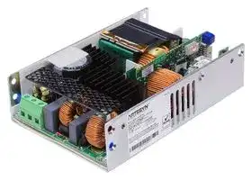
CNS658-MU
AC/DC Open Frame Power Supply (PSU), Medical, 1 Output, 650W @ 400LFM, 400 W, 90V AC to 264V AC
⚠️ Reference pricing provided. In case of supply shortages, we will connect you with our trusted procurement partners to ensure your project's continuity.
- Manufacturer: ARTESYN / ADVANCED ENERGY
- Product type: AC / DC Open Frame Power Supplies
- No. of Outputs:1 Output; Power Rating (Covection Cooling):400W; Power Rating (Forced Cooling):650W @ 400LFM; Input Voltage VAC:90V AC to 264V AC; Power Supply Output Type:Adjustable, Fixed;
- SVHC: To Be Advised
- Product Range: CNS650-M Series
- No. of Outputs: 1 Output
- Input Voltage VAC: 90V AC to 264V AC
- Power Supply Output Type: Fixed
- Output Current - Output 1: 13.5A
- Output Current - Output 2: -
- Output Current - Output 3: -
- Output Current - Output 4: -
- Output Voltage - Output 1: 48VDC
- Output Voltage - Output 2: -
- Output Voltage - Output 3: -
- Output Voltage - Output 4: -
- Power Supply Applications: Medical
- Power Rating (Forced Cooling): 650W @ 400LFM
- Power Rating (Convection Cooling): 400W
| Delivery and price | |
|---|---|
| Units per pack | 5 |
| Price | 182.97 € |
| Current stock | 10+ |
| Lead time | 30 days |
Datasheet

## **ARTESYN CNS650-M SERIES** 650 W AC-DC Power Supplies

Advanced Energy's Artesyn CNS650-MU series of single output open-frame AC-DC power supplies are offered 12 V, 24 V, or 48 V outputs with +15% trim range. Each power supply comes with a 12 V fan output and 5 V standby. All models feature ITE and medical safety approvals and accept a universal input of 90 to 264 VAC. Depending on operating conditions, its 4'' x 6'' x 1.54'' compact and high density "U-Channel" construction delivers up to 400 W of output power with free air convection cooling and up to 650 W with 400 LFM of forced air. These power supplies are ideal for industrial systems as well as for medical applications.

## **SPECIAL FEATURES**

## **SAFETY**

   - UL+CUL ES 60601-1 UL 60601-1 UL 62368-1

- Designed for forced air and natural convection cooling

- Medical and ITE safety approvals, 2x MOPP

   - TÜV EN 60601-1

- PMBus® interface

   - DEMKO EN 62368-1

- Active current share with OR-ing FET

   - CB IEC 60950-1 IEC 60601-1 IEC 62368-1

- Dual fused

- Type BF ready

   - CCC GB4943.1/GB9254 GB17625.1

- Active Power Factor Correction, 61000-3-2 compliant

   - CE LVD, RoHS

- Built-in Class B EMI filter

   - UKCA Mark

- Less than 1U high

   - **  CNS650-M tested according to the medical standard IEC 60601-1 3.1 Edition.

- 4" x 6" U-channel construction (open-frame or end-fan variants available for 12 V)

## **AT A GLANCE**

## **Total Power:**

**650 W**

## **Input Voltage:**

**90 to 264 VAC**

**# of Outputs:**

**Single**

- <500 mW no-load power consumption

- 80 PLUS® certified (-ME model)

- Three years warranty (consult factory for extended terms)

©2025 Advanced Energy Industries, Inc.

**CNS650-M**

**==> picture [480 x 415] intentionally omitted <==**

**----- Start of picture text -----**<br>
ELECTRICAL SPECIFICATIONS<br>Input<br>Input voltage ra nge 90 to 264 VAC or 127 to 350 VDC<br>Frequency 47 to 63 Hz (360 to 400 Hz with higher leakage)<br>Inrush current 50 Apk, cold start<br>Leakage current <300 µA (using UL test method)<br>No load power < 500 mW<br>Output<br>Maximum power 650 W, forced-air cooling (750 W peak)<br>400 W, free-air natural convection cooling (650 W peak)<br>Adjustment range -0% to +15%<br>Holdup time 20 ms @ 400 W<br>Fan output 12 V @ 1.0 A (forced air)<br>12 V @ 0.5 A (natural convection)<br>Standby output 5 V @ 2.0 A (forced air)<br>5 V @ 1.0 A (natural convection)<br>Control and Protection<br>Serial bus interface PMBus®<br>Current share Active<br>Remote sense 2-wire (+ and -)<br>Remote inhibit Pull inhibit low = main & fan output OFF (5 V standby is ON)<br>Pull inhibit high (or floating) = all outputs ON<br>AC OK Active high when normal AC input is present (with internal 10 kOhm pull up to 3.3 V)<br>DC OK Active high when main O/P is within regulation (with internal 10 kOhm pull up to 3.3 V)<br>Smart fan control Monitor, control and override<br>Overvoltage protection Latch (AC recyle or inhibit toggle required for PSU restart)<br>Overload protection Auto-recovery (constant current mode down to 50% Vout)<br>Overtemperature protection Auto-recovery with hysteresis<br>**----- End of picture text -----**<br>


**==> picture [480 x 121] intentionally omitted <==**

**----- Start of picture text -----**<br>
ENVIRONMENTAL SPECIFICATIONS<br>Operating temperature -20 °C to +80 °C (derate at 50 °C), startup at -40 °C<br>Storage temperature -40 °C to +85 °C<br>Operating humidity 5% to 95% (non-condensing)<br>Non-operating humidity 5% to 95% (non-condensing)<br>Maximum altitude 5000 m (3000 m for medical), derating may apply<br>**----- End of picture text -----**<br>


**2 advancedenergy.com**

**CNS650-M**

## **OTHER SPECIFICATIONS**

**==> picture [480 x 134] intentionally omitted <==**

**----- Start of picture text -----**<br>
Isolation 4000 VAC (input to output)<br>1500 VAC (input to PE, output to PE)<br>Line harmonics EN 61000-3-2, Class A<br>ESD immunity EN 61000-4-2, ±15kV (air) / ±8kV (contact) - Criterion A<br>Conducted EMI Level B, CISPR 22 and FCC Part 15<br>Radiated EMI Level B, CISPR 22 and FCC Part 15 (with cover)<br>Surge immunity EN 61000-4-5, Level 3 - Criterion A, Level 4 - Criterion C<br>Medical EMC EN 60601-1-2: 2014 (cover maybe required for some tests)<br>MTBF   > 950 KHrs, 25 °C, 410 W natural convection<br>(Telcordia, Issue 3, Method 1, Case 3) > 1.3 MHrs, 25 °C, 650 W forced air<br>**----- End of picture text -----**<br>


## **ORDERING INFORMATION**

**==> picture [479 x 131] intentionally omitted <==**

**----- Start of picture text -----**<br>
Max.  Max.<br>Vout Adjust  Max. Peak  Max. Peak<br>Model Number Output  Range   Minimum  Continuous  Load  Continuous  Load  Regulation3 Ripple (p-p)4<br>Voltage Load Load   1 Load   2<br>(-0% / +15%) (Free Air) (Free Air) (Forced Air)2 (Forced Air)<br>  CNS653-ME5, 6 12 V 12 - 13.8 V 0 A 54.2 A 62.5 A NA NA ±2% 120 mV<br>CNS653-MF5 12 V 12 - 13.8 V 0 A 30.8 A 54.2 A 54.2 A 62.5 A ±2% 120 mV<br>CNS653-MU 12 V 12 - 13.8 V 0 A 33.3 A 54.2 A 54.2 A 62.5 A ±2% 120 mV<br>CNS655-MU 24 V 24 - 27.6 V 0 A 16.7 A 27.1 A 27.1 A 31.3 A ±2% 240 mV<br>CNS655-ME 24 V 24 - 27.6  V 0 A 27.1 A 31.3 A NA NA ±2% 240 mV<br>CNS658-MU 48 V 48 - 55.2 V 0 A 8.3 A 13.5 A 13.5 A 15.6 A ±2% 480 mV<br>**----- End of picture text -----**<br>


1 Peak load current not to exceed 10 seconds, Ta = 50 °C.

2 Requires at least 400 LFM of airflow.

3 At 25 °C including factory setpoint, line voltage and load current variations.

4 Peak-to-peak ripple measured at the output terminal with 20 MHz bandwidth and 10 µF (tantalum capacitor) in parallel with 0.1 µF capacitor across the output.

5 Optional suffix “-ME” (end-fan) and “-MF: (open-frame) available on the 12 V output.

6 80 PLUS certified.

**advancedenergy.com       3**

**CNS650-M**

## **INPUT CONNECTIONS (-MU AND -MF SUFFIX)**

**==> picture [478 x 59] intentionally omitted <==**

**----- Start of picture text -----**<br>
Pin Function Power Supply Side System Side<br>TB1 PE<br>Dinkle EHK762V-03P Recommended Wire Size: AWG<br>TB2 L2/Neutral<br>Max Torque: 4kgf-cm #22 to #14<br>TB3 L1/Line<br>**----- End of picture text -----**<br>


## **INPUT CONNECTIONS (-ME SUFFIX)**

**==> picture [478 x 30] intentionally omitted <==**

**----- Start of picture text -----**<br>
Pin Function Power Supply Side System Side<br>IEC Inlet Input AC IEC 60320 C14 (Male) IEC Cord C13 (Female)<br>**----- End of picture text -----**<br>


## **OUTPUT CONNECTIONS**

**==> picture [478 x 73] intentionally omitted <==**

**----- Start of picture text -----**<br>
Pin Function Power Supply Side System Side<br>BAR1 -Vout<br>Molex 19099-0032 or 19141-0063<br>BAR2 -Vout Output Terminal Screw: M4X8 (4X) for AWG #16 to #14<br>BAR3 +Vout Max Torque: 10kgf-cm Molex  19099-0048 or 19141-0083<br>for AWG #12 to #10<br>BAR4 +Vout<br>**----- End of picture text -----**<br>


**4 advancedenergy.com**

**CNS650-M**

## **OTHER OUTPUT AND CONTROL CONNECTIONS (CONNECTOR J304)**

**==> picture [479 x 298] intentionally omitted <==**

**----- Start of picture text -----**<br>
Pin Designation Description<br>1 5VSB +5 V Standby Output J304 20-Pin Connector (PSU Side):<br>2 5VSB +5 V Standby Output Landwin:  2052P20008T or<br>3 5VSB_GND +5 V Standby Output Return/Ground CviLux:     CI0120P1HD0-LF<br>4 SCL Serial Clock Signal (I2C)<br>5 A0 EEPROM Address Recommended Mating Connectors:<br>6 SDA Serial Data Signal (I2C) CviLux:    CI0120SD000 (housing)<br>7 I_SHARE Active Current Share                 CI01TD21PE0 (contact pins)<br>8 SYS_GND Return Ground for Signals and I2C Landwin:  2050S2000 (housing)<br>9 12VFAN 12 V Fan Output                 2053T021V (contact pins)<br>10 REMOTE INHIBIT Output Inhibit Pin (Main Output) JST:         PHDR-20VS (housing)<br>11 FAN_RTN 12 V Fan Output Return/Ground                 SPHD-001T-P0.5 (contact pins)<br>12 VIN_GOOD Input Line OK Signal<br>13 FAN_PWM1 FAN PWM<br>14 PWOK Output Power OK Signal See ACCESSORIES Section<br>15 FAN_TACH1 Fan1 Tacho Signal<br>16 FAN_OVERRIDE External Fan Sensor for Override<br>17 FAN_FAIL Fain Fail Signal<br>18 FAN_FAULT_EN FAN Fault Enable Due to Low RPM<br>19 REMOTE_SENSE+ Positive Remote Sense<br>20 REMOTE_SENSE- Remote Sense Return<br>**----- End of picture text -----**<br>


## **FAN OUTPUT CONNECTOR FOR -MU, -MF SUFFIX (CONNECTOR J306)**

**==> picture [479 x 127] intentionally omitted <==**

**----- Start of picture text -----**<br>
Pin Function Description<br>1 12VFAN 12 V fan output  J306 4-Pin Connector (PSU Side):<br>2 FAN_RTN 12 V fan return CviLux:   CI0104P1HK0-LF<br>3 FAN_PWM1 Fan PWM Landwin: 2003P0401V<br>4 FAN_TACH1 Fan1 tacho signal Recommended Mating Connectors:<br>CviLux:   CI0104S0000 (housing)<br>CviLux:   CI01T01MPP0 (contact pins)<br>Landwin: 2001S0400 (housing)<br>Landwin: 2005T011R (contact pins)<br>**----- End of picture text -----**<br>


**advancedenergy.com       5**

**CNS650-M**

## **MECHANICAL DRAWINGS (“-MU” SUFFIX FOR U-BASE CONSTRUCTION/12 V, 24 V AND 48 V)**

**==> picture [421 x 577] intentionally omitted <==**

**----- Start of picture text -----**<br>
16.2 120<br>PEM F-M3-1 (2X)<br>2.5 mm max penetration depth from face of side chassis<br>PE<br>INPUT CONNECTOR N C40 OUTPUT TERMINALS<br>DINKLE EHK762V-03P L SCREW M4X8 (4X)<br>TORQUE: 4kgf-cm MAX. TORQUE: 10kgf-cm MAX.<br>L-0P<br>J306 FAN<br>CONNECTOR J304<br>2 0-WAY<br>SIGNAL CONNECTOR<br>L1<br>D1 VR408<br>TRIMPOT FOR OUTPUT ADJUSTABILITY<br>PEM F-M3-1 (2X) COUNTER-CLOCKWISE:<br>MODEL LABEL INCREASE OUTPUT VOLTAGE<br>16.2 120<br>PEM F-M3-1 (4X)<br>3.0 MM MAX<br>PENETRATION<br>DEPTH FROM<br>FACE OF BOTTOM<br>CHASSIS 26.2 100 (2X)<br>152. 4 0.5 1.9 REF<br>Thermal Hot Spot Reference<br>Component Temperature Limit (-MU)<br>D1 (AC bridge diode) 105 °C<br>L1 (PFC choke) 115 °C<br>C40 (output cap) 100 °C<br>L-output (output choke) 125 °C<br>Do not exceed indicated temperature limits to ensure operation is<br>within the component thermal derating limits. Measure the component<br>temperatures using K type thermocouples.<br>39.2 30 (2X)<br>0.5<br>30 (2X) 39.2<br>13.3<br> 0.5<br>75 (2X)<br>101.6<br>**----- End of picture text -----**<br>


Unit weight (-MU suffix): 800 g

**6 advancedenergy.com**

**CNS650-M**

## **MECHANICAL DRAWINGS (“-MF” SUFFIX FOR OPEN-FRAME CONSTRUCTION/12 V ONLY)**

**==> picture [475 x 319] intentionally omitted <==**

**----- Start of picture text -----**<br>
152.4 0.5 1.9 REF<br>4.5 141.9<br>43.9 1<br>R oHS LABEL<br>PE<br>C40<br>INPUT CONNECTOR N O UTPUT TERMINALS<br>DINKLE EHK762V-03P L SCREW M4X8 (4X)<br>TORQUE: 4kgf-cm MAX. L-0P TORQUE: 10kgf-cm MAX.<br>J304<br>2 0-WAY<br>SIGNAL CONNECTOR<br>L1<br>4.5 D1 143.4 4X M3 VR408<br>MOUNTING  TRIMPOT FOR OUTPUT ADJUSTABILITY<br>HOLE COUNTER-CLOCKWISE:<br>INCREASE OUTPUT VOLTAGE<br>J306 FAN CONNECTOR<br>MODEL LABEL<br>1<br>7<br>12.<br>0.5<br>88.8 88.3<br>96.8<br>4<br>0.5 REF<br>0.5<br>34.1<br>2.5 REF<br>**----- End of picture text -----**<br>


**==> picture [231 x 117] intentionally omitted <==**

**----- Start of picture text -----**<br>
Thermal Hot Spot Reference<br>Component Temperature Limit (-MF)<br>D1 (AC bridge diode) 120 °C<br>L1 (PFC choke) 120°C<br>C40 (output cap) 100 °C<br>L-output (output choke) 125 °C<br>Do not exceed indicated temperature limits to ensure operation is<br>within the component thermal derating limits. Measure the component<br>temperatures using K type thermocouples.<br>**----- End of picture text -----**<br>


Unit weight (-MF suffix): 650 g

**advancedenergy.com       7**

**CNS650-M**

## **MECHANICAL DRAWINGS (“-ME” SUFFIX FOR END-FAN CONSTRUCTION/12 V ONLY)**

**==> picture [315 x 468] intentionally omitted <==**

**----- Start of picture text -----**<br>
PEM F-M3-1 (2X)<br>120 16.2<br>4.8 REF 177.8 0.5<br>AC INLET<br>152.4<br>20<br>120 16.2 1.9 REF<br>MODEL LABEL<br>PEM F-M3-1 (2X)<br>PEM F-M3-1 (4X)<br>(2X) 100 26.2<br>(2X) 30<br>55.8<br>0.5<br>101.6<br>0.5<br>40<br>(2X) 30<br>13.3<br>(2X) 75<br>**----- End of picture text -----**<br>


**==> picture [86 x 56] intentionally omitted <==**

**----- Start of picture text -----**<br>
OUTPUT TERMINALS<br>SCREW M4X8 (4X)<br>TORQUE: 10kgf-cm MAX.<br>J304<br>2 0-WAY<br>SIGNAL CONNECTOR<br>**----- End of picture text -----**<br>


VR408 TRIMPOT FOR OUTPUT ADJUSTABILITY COUNTER-CLOCKWISE: INCREASE OUTPUT VOLTAGE

**8 advancedenergy.com**

**CNS650-M**

## **PERFORMANCE CURVES**

**==> picture [214 x 137] intentionally omitted <==**

**----- Start of picture text -----**<br>
Output Power Derating<br>700<br>600<br>500<br>400<br>300<br>200 Convection (MF)Convection (MU)<br>400 LFM (MF/MU)<br>100 200 LFM (MF/MU)<br>ME (End Fan)<br>0<br>0 10 20 30 40 50 60 70 80 90<br>Ambient Temperature [°C]<br>Output Power [Watts]<br>**----- End of picture text -----**<br>


Figure 1. Output Power vs. Ambient Temperature at Natural Convection and Forced Air Cooling

**==> picture [212 x 136] intentionally omitted <==**

**----- Start of picture text -----**<br>
CNS653‐Mx (12V) Efficiency Curve<br>96%<br>95%<br>94%<br>93%<br>92%<br>91%<br>115 VAC<br>90% 230 VAC<br>89%<br>0 0.2 0.4 0.6 0.8 1<br>Output Load (% of 650W)<br>Efficiency (%)<br>**----- End of picture text -----**<br>


Figure 3. Typical Efficiency for 12 V Output

**==> picture [212 x 144] intentionally omitted <==**

**----- Start of picture text -----**<br>
CNS658‐Mx (48V) Efficiency Curve<br>96%<br>95%<br>94%<br>93%<br>92%<br>91%<br>115 VAC<br>90% 230 VAC<br>89%<br>0 0.2 0.4 0.6 0.8 1<br>Output Load (% of 650W)<br>Figure 5. Typical Efficiency for 48 V Output<br>Efficiency (%)<br>**----- End of picture text -----**<br>


**==> picture [212 x 154] intentionally omitted <==**

**----- Start of picture text -----**<br>
Output Power VS. Input Line<br>700<br>600<br>500<br>400<br>300<br>Convection (MF)<br>200 Convection (MU)400 LFM (MF/MU)<br>200 LFM (MF/MU)<br>100 ME (End Fan)<br>0<br>90 110 130 150 170 190 210 230 250 270<br>AC Input Line [Vac]<br>Figure 2. Output Power vs. Input Line at Natural Convection and Forced Air<br>Cooling<br>Output Power [Watts]<br>**----- End of picture text -----**<br>


**==> picture [211 x 135] intentionally omitted <==**

**----- Start of picture text -----**<br>
CNS655‐Mx (24V) Efficiency Curve<br>96%<br>95%<br>94%<br>93%<br>92%<br>91%<br>115 VAC<br>90% 230 VAC<br>89%<br>0 0.2 0.4 0.6 0.8 1<br>Output Load (% of 650W)<br>Efficiency (%)<br>**----- End of picture text -----**<br>


Figure 4. Typical Efficiency for 24 V Output

**Estimated Service Life vs. Component Temp**

**==> picture [197 x 97] intentionally omitted <==**

**----- Start of picture text -----**<br>
150<br>125<br>Esimated Life 100<br>75<br>50<br>25<br>0<br>110 105 100 95 90 85 80 75<br>C40 Temperature [°C]<br>Lifetime [KHrs]<br>**----- End of picture text -----**<br>


Figure 6. Estimated Product Useful Life Based on C40 Case Temperature

**==> picture [212 x 132] intentionally omitted <==**

**----- Start of picture text -----**<br>
CNS653-ME Fan Noise vs. Load<br>60<br>50<br>40<br>30<br>20<br>10<br>0<br>0 0.2 0.4 0.6 0.8 1<br>LOAD<br>SPL dB(A)<br>**----- End of picture text -----**<br>


Figure 7. CNS653-ME (End Fan) Typical Audible Noise Level vs. Output Load at 90 VAC, ~30 °C Ambient.

**advancedenergy.com       9**

**CNS650-M**

**ACCESSORIES Orderable Part Number Description Description** 73-788-001 J304 (20 Pin) Mating Connector with PIN 20 PIN 19 0.3 m wires attached PIN 3 PIN 2 PIN 1 300 ± 5 mm ~~ss.~~ CNS-BBAR-KIT Output Bussbar Extension Kit for Vertical Wire Interface iS Pe. Bic, eee 73-769-002 USB to I2C Adaptor for PMBus Communication

**10 advancedenergy.com**

**==> picture [596 x 270] intentionally omitted <==**

## **ABOUT ADVANCED ENERGY**

Advanced Energy (AE) has devoted more than three decades to perfecting power for its global customers. AE designs and manufactures highly engineered, precision power conversion, measurement and control solutions for mission-critical applications and processes.

Our products enable customer innovation in complex applications for a wide range of industries including semiconductor equipment, industrial, manufacturing, telecommunications, data center computing, and medical. With deep applications know-how and responsive service and support across the globe, we build collaborative partnerships to meet rapid technological developments, propel growth for our customers, and innovate the future of power.

## **TRUST**

For international contact information, visit advancedenergy.com.

powersales@aei.com (Sales Support) productsupport.ep@aei.com (Technical Support) +1 888 412 7832

Specifications are subject to change without notice. Not responsible for errors or omissions. ©2025 Advanced Energy Industries, Inc. All rights reserved. Advanced Energy®, and AE® are U.S. trademarks of Advanced Energy Industries, Inc.

ENG-CNS650-M-02.11.25
Updated at April 22, 2026
About Novapart
Novapart is a B2B electronic component broker specialising in stock shortages and cost reduction. We source hard-to-find parts and identify compliant alternatives across a catalogue of 410,000+ components from 500+ manufacturers.
Learn more →Stock Shortage Specialist
When a component is unavailable, discontinued or has an unacceptable lead time, we tap into our network of vetted European and Asian distributors to source what you need — without compromising on quality or traceability.
Request a quote →Compliant Alternatives
We identify pin-to-pin, electrically equivalent substitutes that meet the same certifications (RoHS, AEC-Q100, REACH) as your original specification — validated against datasheets, not just part numbers. Often at a lower cost.
BOM Analysis service →