
Image not available
Illustrative purposes only

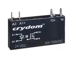
CN100D05
Solid State Relay, SPST-NO, 6 A, 100 VDC, Through Hole, PC Pin, Zero Voltage Turn On
⚠️ Reference pricing provided. In case of supply shortages, we will connect you with our trusted procurement partners to ensure your project's continuity.
- Manufacturer: SENSATA/CRYDOM
- Product type:
- SVHC: No SVHC (12-Jan-2017)
- Load Current: 6A
- Product Range: CN Series
- Relay Mounting: Through Hole
- Switching Mode: Zero Voltage Turn On
- Relay Terminals: PC Pin
- Control Voltage Max: 12VDC
- Control Voltage Min: 3VDC
- Contact Configuration: SPST-NO
- Operating Voltage Max: 100VDC
- Operating Voltage Min: 0VDC
| Delivery and price | |
|---|---|
| Units per pack | 20 |
| Price | 21.87 € |
| Current stock | 10+ |
| Lead time | 30 days |
Datasheet

## **| CN SERIES**

## PLUG-IN/PCB MOUNT SOLID STATE RELAYS

Sensata | Crydom CN Series AC & DC Output Plug-in Solid State Relays are thin 5 mm wide relays ideally suited for high density PCB applications. CN Series SSRs are designed to be pluggable into industry standard relay sockets or solderable into printed circuit boards, and they are available in ratings of 2 Amps at 24 to 280 VAC or 0.1 to 6 Amps at 0 to 100 VDC. They are UL recognized and CE compliant.

## Features

- 5 mm Mini SIP SSR

- Ratings 24 VDC @ 3.5 A, 48 VDC @ 100mA, 100 VDC @ 6 A and 240 VAC @ 2 A

- DC Control, 5, 24 and 60 V

- UL & cUL recognized @ 40°C, 100K-Cycle Endurance Test

- CE & RoHS Compliant

## Applications

- Automation Equipment

- Test Equipment

- Packaging equipment

- Valves & Solenoids

- Vending Equipment

- Medical Equipment

## **PRODUCT SELECTION**

|**Control Voltage**|**3.5 A**|**100mA**|**6 A**|**2 A**|
|---|---|---|---|---|
|**3-12 VDC**|CN024D05|CN048D05|CN100D05|CN240A05|
|**15-30 VDC**|CN024D24|CN048D24|CN100D24|CN240A24|
|**38-72 VDC**|CN024D60|CN048D60||CN240A60|


## **SPECIFICATIONS**

Output[(1)]

|**Description**<br>~~I~~<br>~~PO~~|**CN024Dxx**<br>~~I~~<br>~~(~~|**CN048Dxx**<br>~~I~~<br>~~(~~|**CN100Dxx**<br>~~I~~<br>~~(~~|**CN240Axx**<br>~~I~~|
|---|---|---|---|---|
|**Operating Voltage**<br>~~I~~<br>~~PO~~|0-24 VDC<br>~~I~~<br>~~(~~|0-48 VDC<br>~~I~~<br>~~(~~|0-100 VDC<br>~~I~~<br>~~(~~|24-280 VAC (47-63Hz)<br>~~I~~|
|**Maximum Load Current @ 40°C(2)**<br>~~PO~~|3.5 A<br>~~eee~~|100mA<br>~~a~~<br>~~ee~~|6 A<br>~~a~~<br>~~ee~~|2 A<br>~~a~~<br>~~ee~~|
|**Minimum Load Current [mA]**<br>~~i~~<br>~~PO~~|1<br>~~i~~<br>~~eee~~|1<br>~~i~~<br>~~ee~~|1<br>~~i~~<br>~~ee~~|70<br>~~i~~<br>~~ee~~|
|**Maximum Blocking Voltage**<br>~~PO~~|30 VDC<br>~~eee~~<br>~~a~~|60 VDC<br>~~ee~~<br>~~a~~|100 VDC<br>~~ee~~|600 VDC<br>~~ee~~<br>~~|~~|
|**Maximum Surge Current [Apk]**<br>~~PO~~<br>~~PO~~|9 (10ms)<br>~~eee~~<br>~~a~~|0.3 mA (10ms)<br>~~ee~~<br>~~a~~|45 (10ms)<br>~~ee~~|115/120 (50/60 Hz, 1 cycle)<br>~~ee~~<br>~~|~~|
|**Maximum I²t for fusing 50/60Hz (1/2 cycle) [A² sec]**<br>~~pO~~|N/A|N/A|N/A|66/60|
|**Typical On-State Voltage Drop @ Rated Current (V)**<br>~~pO~~<br>~~PO~~|0.4|1.0|0.1|1.1 (peak)|
|**Maximum Off-State Leakage Current @ Rated**<br>**Voltage [mA]**|0.001|0.001|0.001|4.0|


Page 1

www.sensata.com

Copyright © 2021 Sensata Technologies, Inc.

|**Maximum PWM (Hz)(3)**|500|500|40|N.A.|
|---|---|---|---|---|
|**Minimum Off-State dv/dt @ Maximum Rated Voltage**<br>**[V/μsec]**|N/A|N/A|N/A|500|
|**Switch Confguration**|N.O.|N.O.|N.O.|N.O.|


## Input Specifications for CN024[(1)]

**==> picture [541 x 129] intentionally omitted <==**

**----- Start of picture text -----**<br>
Description CN024D05 CN024D24 CN024D60<br>Control Voltage Range 3-12 VDC 15-30 VDC 38-72 VDC<br>Must Turn On Voltage 3 VDC 15 VDC 38 VDC<br>Must Turn Off Voltage 1 VDC 5 VDC 5 VDC<br>Nominal Input Impedance 500 Ohm 3.5K Ohm 20K Ohm<br>Typical Input Current 10mA @ 5 VDC 7mA @ 24 VDC 3mA @ 60 VDC<br>Typical Turn-On Time [μsec]  120 350 400<br>Typical Turn-Off Time [μsec]  100 80 70<br>**----- End of picture text -----**<br>


## Input Specifications for CN048[(1)]

**==> picture [541 x 129] intentionally omitted <==**

**----- Start of picture text -----**<br>
Description CN048D05 CN048D24 CN048D60<br>Control Voltage Range 3-12 VDC 15-30 VDC 38-72 VDC<br>Must Turn On Voltage 3 VDC 15 VDC 38 VDC<br>Must Turn Off Voltage 1 VDC 5 VDC 5 VDC<br>Nominal Input Impedance 1.25K Ohm 3K Ohm 20K Ohm<br>Typical Input Current 12mA @ 5 VDC 8mA @ 24 VDC 3mA @ 60 VDC<br>Typical Turn-On Time [μsec]  20 20 20<br>Typical Turn-Off Time [μsec]  130 130 130<br>**----- End of picture text -----**<br>


## Input Specifications for CN100[(1)]

**==> picture [542 x 129] intentionally omitted <==**

**----- Start of picture text -----**<br>
Description CN100D05 CN100D24<br>Control Voltage Range 3-12 VDC 15-30 VDC<br>Must Turn On Voltage 3 VDC 15 VDC<br>Must Turn Off Voltage 1 VDC 5 VDC<br>Nominal Input Impedance 420 Ohm 3K Ohm<br>Typical Input Current 12mA @ 5 VDC 8mA @ 24 VDC<br>Maximum Turn-On Time [μsec]  400 800<br>Maximum Turn-Off Time [μsec]  180 180<br>**----- End of picture text -----**<br>


## Input Specifications for CN240[(1)]

**==> picture [541 x 129] intentionally omitted <==**

**----- Start of picture text -----**<br>
Description CN240A05 CN240A24 CN240A60<br>Control Voltage Range 3-12 VDC 15-30 VDC 38-72 VDC<br>Must Turn On Voltage 3 VDC 15 VDC 38 VDC<br>Must Turn Off Voltage 1 VDC 5 VDC 5 VDC<br>Nominal Input Impedance 240 Ohm 3.5K Ohm 20K Ohm<br>Typical Input Current 15mA @ 5 VDC 6mA @ 24 VDC 4mA @ 60 VDC<br>Typical Turn-On Time [μsec]  [(4)] 1/2 Cycle 1/2 Cycle 1/2 Cycle<br>Typical Turn-Off Time [μsec]  1/2 Cycle 1/2 Cycle 1/2 Cycle<br>**----- End of picture text -----**<br>


Page 2

www.sensata.com

Copyright © 2021 Sensata Technologies, Inc.

## **GENERAL SPECIFICATIONS[(1)]**

**==> picture [542 x 161] intentionally omitted <==**

**----- Start of picture text -----**<br>
Description Parameters<br>Dielectric Strength, Input/Output/Base (50/60Hz)  [(5)] 2.5KV<br>Maximum Capacitance, Input/Output 1.5 pF<br>Ambient Operating Temperature Range -20 to 80°C<br>Ambient Storage Temperature Range -20 to 100°C<br>Weight (typical) 0.14 oz. (4.05g)<br>Housing Material UL 94 V0<br>Overvoltage Category lll<br>Pollution Degree 2<br>Degree of protection (Encapsulation) IP67<br>**----- End of picture text -----**<br>


## **THERMAL DERATE INFORMATION**

**==> picture [169 x 145] intentionally omitted <==**

**----- Start of picture text -----**<br>
CN024Dxx<br>3.5<br>3<br>2.5<br>2<br>1.5<br>1<br>0.5<br>0<br>20 30 40 50 60 70 80<br>Ambient Temperature (ºC)<br>Load Current (Amps)<br>**----- End of picture text -----**<br>


## **CN240Axx**

**==> picture [161 x 115] intentionally omitted <==**

**----- Start of picture text -----**<br>
2<br>1.5<br>1<br>0.5<br>0<br>20 30 40 50 60 70 80<br>Ambient Temperature (ºC)<br>Load Current (Amps)<br>**----- End of picture text -----**<br>


## **CN048Dxx**

**==> picture [208 x 132] intentionally omitted <==**

**----- Start of picture text -----**<br>
0.1<br>0.08<br>0.06<br>0.04<br>0.02<br>0<br>20 30 40 50 60 70 80<br>Ambient Temperature (ºC)<br>Load Current (Amps)<br>**----- End of picture text -----**<br>


**CN100Dxx**

**==> picture [215 x 136] intentionally omitted <==**

**----- Start of picture text -----**<br>
6<br>5<br>4<br>3<br>2<br>1<br>0<br>20 30 40 50 60 70 80<br>Ambient Temperature (ºC)<br>Load Current (Amps)<br>**----- End of picture text -----**<br>


Page 3

www.sensata.com

Copyright © 2021 Sensata Technologies, Inc.

## **WIRING DIAGRAM**

**==> picture [540 x 547] intentionally omitted <==**

Page 4

www.sensata.com

Copyright © 2021 Sensata Technologies, Inc.

## **MECHANICAL SPECIFICATIONS**

Tolerances: ±0.02 in / 0.5 mm  All dimensions are in: inches [millimeters]

**==> picture [282 x 218] intentionally omitted <==**

**----- Start of picture text -----**<br>
 0.99<br>[25.2]<br> 0.84<br>[21.4]<br> 0.20<br> 0.08 [5.0]<br>[1.9]<br>0.20<br> 1.10 [5.0]<br>[28.0]<br>0.59<br>[15.0]<br>14 13(+) A1+   A2- 0.15<br>[3.8]<br>0.15<br>[3.8]<br>0.02<br>0.040 ±.005 0.020 ±.005 0.06 [0.4]<br>[1.00 ±.13] [0.50 ±.13] [1.4]<br>(2PLACES) (2PLACES)<br>**----- End of picture text -----**<br>


## **INSTALLATION INSTRUCTIONS**

## Mounting on a Socket

The CN Series relays can be mounted in a DIN rail socket. The DRSCN sockets provide a convenient and easy way to install CN Series Solid State Relays on a standard 35 mm DIN rail.

Please read all installation instructions before using the sockets and relays.

- Match CN Series SSR to appropriate DRSCN socket part number to create an assembly (See Relay/Socket Compatibility)

- Insert the CN SSR on the socket

- Mount the socket on the DIN rail

- Wire the socket to the control side. AWG #24-14 solid, AWG #24-14 stranded (0.2-2.1 mm2)

- Wire the socket to the load side. AWG #24-14 solid, AWG #24-14 stranded (0.2-2.1 mm2)

- Maximum torque: 5-7 lb-in (0.56-0.8 Nm)

- If multiple units are installed be sure to follow derating curves for assemblies

**==> picture [541 x 34] intentionally omitted <==**

**----- Start of picture text -----**<br>
TABLE 1. Relay/Socket Compatibility<br>SSR Part. No. DRSCN30 DRSCN24 DRSCN05<br>**----- End of picture text -----**<br>


|**TABLE 1. Relay/Socket Compatibility**|**TABLE 1. Relay/Socket Compatibility**|**TABLE 1. Relay/Socket Compatibility**|**TABLE 1. Relay/Socket Compatibility**|
|---|---|---|---|
|**SSR Part. No.**|**DRSCN30**|**DRSCN24**|**DRSCN05**|
|||||
|**CN024D05**|**•**||**•**|
|**CN024D24**|**•**|**•**||
|**CN048D05**|**•**||**•**|
|**CN048D24**|**•**|**•**||
|**CN240A05**|**•**||**•**|
|**CN240A24**|**•**|**•**||
|**CN100D05**|**•**||**•**|
|**CN100D24**|**•**|**•**||


Page 5

www.sensata.com

Copyright © 2021 Sensata Technologies, Inc.

- Installing a CN Series solid state relay in a socket that does not have matching input/output specifications may result in damage to either the relay, socket, or both, and/or in non-operation.

- Maximum output rating for DRSCN Series sockets is 250 V, 6 Amps regardless of chosen SSR.

- Proper polarity must be observed for DC input control voltage sockets being terminal A1+ positive with respect to terminal A2-.

- For AC loads, the AC line can be wired to either DRS socket terminal 11 or terminal 14. The AC load may also be wired on either the line or neutral side of the SSR. For DC loads, the proper polarity must be observed for the power supply, load and DRS socket with terminal 13 being positive with respect to terminal 14.

- DC inductive loads must be diode suppressed.

- All terminals feature screw M3 slotted drive.

## **WIRING DIAGRAMS**

**==> picture [515 x 124] intentionally omitted <==**

**----- Start of picture text -----**<br>
DRSCN30 DRSCN05, DRSCN24<br>| corydom oO } |<br>ecernatnoneen ve ML: CE<br>DRSCN30 © wo<br>Bes Mae A SOCKET A<br>Input Voltage SVDC Input Voltage 24VDC 11/13+ PART HUMBER<br>Load Load<br>Control Supply Control Supply<br>Load<br>Al+ Eau 14 Td oR RATINGS SHOULD NOT<br>Wh ce ON B A2-cl] pay+ 11/130)ts Load<br>B<br>**----- End of picture text -----**<br>


## **Mounting on a Printed Circuit Board**

When different kinds of packages are mounted on PC board, temperature rise at soldering lead is dependent on package size. Therefore, set the lower temperature soldering condition than the conditions of item “Soldering profile”, and confirm the temperature condition of actual usage before soldering.

When soldering condition exceeds our recommendation, the SSR characteristics may be adversely affected. It may occur package crack or power electronics failures because of thermal expansion unconformity and resin strength reduction.

Solder creepage, wettability, or soldering strength will be affected by the soldering condition or used soldering type.

## **Soldering Profile**

The classification temperature (Tc) of this product is 245ºC (473ºF) and the maximum dwell time (Tp) is 30 seconds, the body temperature of this device may be (Tc - 5)ºC or greater. The classification temperature sets the Maximum Body Temperature allowed for this device during lead-free reflow processes, maximum 1 cycle for reflow is allowed. For any other processes, the guidelines of J-STD-020 must be observed.

## **Manual soldering method**

Temperature: 350ºC (662ºF) to 400°C (752ºF), within 3s, electrical power 30 to 60W

## **Recommended PCB hole layout:**

Tolerances: ±0.02 in / 0.5 mm All dimensions are in: inches [millimeters]

Page 6

www.sensata.com

Copyright © 2021 Sensata Technologies, Inc.

**==> picture [543 x 682] intentionally omitted <==**

**----- Start of picture text -----**<br>
ORDERING OPTIONS Example : CN240A24R<br>© Wi<br>CN 240A 24 R<br>Series = |<br>CN<br>Operating Voltage<br>So<br>240A:  240 VAC, 2 A<br>024D:  24 VDC, 3.5 A<br>048D:  48 VDC, 0.1 A<br>100D:  100 VDC, 6 A<br>Control Voltage<br>05:  3-12 VDC<br>24:  15-30 VDC<br>60:  38-72 VDC<br>:<br>Switching Mode (AC Output only)<br>Required for valid part number<br>Blank:  Zero Voltage Turn-On For options only and not required for valid part<br>ee R:  Random Turn-On e number<br>ACCESSORIES<br>@<br>DRSCN Series DIN Rail Mountable Sockets<br>DRSCN05, DRSCN24, DRSCN30<br>•  Sockets are fully compatible with CN series SSRs<br>•  6.2 mm wide<br>•  LED status indicator<br>•  Socket clip fits all standard 35 mm<br>•  DIN rail profiles<br>•  UL & cUL recognized, CE & RoHS compliant<br>Ce RELAY/SOCKET COMPATIBILITY  [G, H]<br>fe SSR PN DR Socket PN O Socket Input Voltage<br>CN024D05<br>CN048D05<br>DRSCN05 3-12 VDC<br>CN100D05<br>CN240A05<br>CN024D24<br>CN048D24<br>DRSCN24 15-30 VDC<br>CN100D24<br>CN240A24<br>CN024D05<br>CN024D24<br>CN048D05<br>CN048D24<br>DRSCN30 4-30 VDC<br>CN100D05<br>CN100D24<br>CN240A05<br>CN240A24<br>G  Installing a CN Series solid state relay in a socket that does not have matching input/output specifications may result in non-operation or damage<br>to either the relay, socket or both.<br>H Maximum output rating for DRSCN Series sockets is 250 V / 6 Amps regardless of chosen SSR.<br>**----- End of picture text -----**<br>


Page 7

www.sensata.com

Copyright © 2021 Sensata Technologies, Inc.

## **ID Marker Strips**

## **CNLB, CNLN, CNL2**

**Black Strips** Part no.: CNLB

A package of 10 plastic strips comprising 10 individual unprinted markers which can be placed on sockets’ terminal block for easy identification during the use of multiple units.

**Numbered 1 to 10 Strips** Part no.: CNLN A package of 10 plastic strips comprising 10 markers printed individually from 1 to 10 which can be placed on sockets’ terminal block for easy identification during the use of multiple units.

**Numbered 11 to 20 Strips** Part no.: CNL2 A package of 10 plastic strips comprising 10 markers printed individually from 11 to 20 which can be placed on sockets’ terminal block for easy identification during the use of multiple units.

## **GENERAL NOTES**

> (1) All parameters at 25°C unless otherwise specified.

> (2) See derating curves

> (3) Operating above the specified frequency will damage the SSR (DC output only).

> (4) Turn-on time for random turn-on version is 0.1 ms.

> (5) 3.75KV for CN048Dxx

## **AGENCY APPROVALS & CERTIFICATIONS**

Designed in accordance with the requirements of IEC 62314

## E116950

(Except CN100Dxx)

Page 8

www.sensata.com

Copyright © 2021 Sensata Technologies, Inc.

## **WARNINGS**

## RISK OF MATERIAL DAMAGE AND HOT ENCLOSURE

- The product’s side panels may be hot, allow the product to cool before touching

- Follow proper mounting instructions including torque values

- Do not allow liquids or foreign objects to enter this product

**Failure to follow these instructions can result in serious injury, or equipment damage.**

## HAZARD OF ELECTRIC SHOCK, EXPLOSION OR ARC FLASH

- Disconnect all power before installing or working with this equipment

- Verify all connections and replace all covers before turning on power

**Failure to follow these instructions will result in death or serious injury.**

Sensata Technologies, Inc. (“Sensata”) data sheets are solely intended to assist designers (“Buyers”) who are developing systems that incorporate Sensata products (also referred to herein as “components”). Buyer understands and agrees that Buyer remains responsible for using its independent analysis, evaluation and judgment in designing Buyer’s systems and products. Sensata data sheets have been created using standard laboratory conditions and engineering practices. Sensata has not conducted any testing other than that specifically described in the published documentation for a particular data sheet. Sensata may make corrections, enhancements, improvements and other changes to its data sheets or components without notice. Buyers are authorized to use Sensata data sheets with the Sensata component(s) identified in each particular data sheet. HOWEVER, NO OTHER LICENSE, EXPRESS OR IMPLIED, BY ESTOPPEL OR OTHERWISE TO ANY OTHER SENSATA INTELLECTUAL PROPERTY RIGHT, AND NO LICENSE TO ANY THIRD PARTY TECHNOLOGY OR INTELLECTUAL PROPERTY RIGHT, IS GRANTED HEREIN. SENSATA DATA SHEETS ARE PROVIDED “AS IS”. SENSATA MAKES NO WARRANTIES OR REPRESENTATIONS WITH REGARD TO THE DATA SHEETS OR USE OF THE DATA SHEETS, EXPRESS, IMPLIED OR STATUTORY, INCLUDING ACCURACY OR COMPLETENESS. SENSATA DISCLAIMS ANY WARRANTY OF TITLE AND ANY IMPLIED WARRANTIES OF MERCHANTABILITY, FITNESS FOR A PARTICULAR PURPOSE, QUIET ENJOYMENT, QUIET POSSESSION, AND NON-INFRINGEMENT OF ANY THIRD PARTY INTELLECTUAL PROPERTY RIGHTS WITH REGARD TO SENSATA DATA SHEETS OR USE THEREOF.

All products are sold subject to Sensata’s terms and conditions of sale supplied at www.sensata.com SENSATA ASSUMES NO LIABILITY FOR APPLICATIONS ASSISTANCE OR THE DESIGN OF BUYERS’ PRODUCTS. BUYER ACKNOWLEDGES AND AGREES THAT IT IS SOLELY RESPONSIBLE FOR COMPLIANCE WITH ALL LEGAL, REGULATORY AND SAFETY-RELATED REQUIREMENTS CONCERNING ITS PRODUCTS, AND ANY USE OF SENSATA COMPONENTS IN ITS APPLICATIONS, NOTWITHSTANDING ANY APPLICATIONS-RELATED INFORMATION OR SUPPORT THAT MAY BE PROVIDED BY SENSATA.

## **CONTACT US**

## **Americas**

+1 (877) 502 5500 sales.crydom@sensata.com

**Europe, Middle East & Africa** +44 (1202) 416170 ssr-info.eu@sensata.com **Asia Pacific** sales.isasia@list.sensata.com China +86 (21) 2306 1500 Japan +81 (45) 277 7117 Korea +82 (31) 601 2004 India +91 (80) 67920890 Rest of Asia +886 (2) 27602006 ext 2808

Mailing Address: Sensata Technologies, Inc., 529 Pleasant Street, Attleboro, MA 02703, USA.

Page 9

Copyright © 2021 Sensata Technologies, Inc.

www.sensata.com

Rev. 06/03/2021 ECN 21137 FDE-07-01 Rev. B
Updated at June 5, 2026
About Novapart
Novapart is a B2B electronic component broker specialising in stock shortages and cost reduction. We source hard-to-find parts and identify compliant alternatives across a catalogue of 410,000+ components from 500+ manufacturers.
Learn more →Stock Shortage Specialist
When a component is unavailable, discontinued or has an unacceptable lead time, we tap into our network of vetted European and Asian distributors to source what you need — without compromising on quality or traceability.
Request a quote →Compliant Alternatives
We identify pin-to-pin, electrically equivalent substitutes that meet the same certifications (RoHS, AEC-Q100, REACH) as your original specification — validated against datasheets, not just part numbers. Often at a lower cost.
BOM Analysis service →