
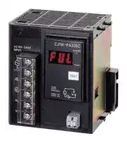


CJ1W-PA205C
Power Supply Module, CJ Series, 240 VAC, DIN Rail Mount, Screw Terminal
- Manufacturer: OMRON INDUSTRIAL AUTOMATION
- Product type: Controller Accessories
- SVHC: To Be Advised
| Delivery and price | |
|---|---|
| Units per pack | 1 |
| Price | 369.39 € |
| Current stock | 10+ |
| Lead time | 30 days |
**CJ-series Power Supply Unit CJ1W-PA/PD**

CSM_CJ1W-PA_PD_DS_E_5_3

## **Equipped with the RUN output for checking the operation status, as well as the replacement notification function for easy maintenance.**

## **Lineup of five models including the AC power supply (25W).**

- Stable power supply is available from the CJ-series CPU Unit to each I/O Units via the dedicated bus. The

**CJ1W-PA205C CJ1W-PA202**

- most suitable Power Supply Unit can be selected among various I/O specifications and/or options.

## **Features**

- The replacement notification function can prevent an overflow of the system due to the power lifetime. (CJ1W-PA205C only)

- Power Supply Unit provides wide variations according to the system scale up to maximum 25 W.

- Power Supply Unit provides wide variations according to the power supply (100 to 240 V AC/ 24 V DC) status.

- The output contact during operation enables you to check the CPU operation. (CJ1W-PA205R only)

- Conforming to the SEMI-F47 Standard. *

- AC input type, 200 V min. input.

**1**

**CJ1W-PA/PD**

## **Ordering Information**

## **International Standards**

- The standards are abbreviated as follows: U: UL, U1: UL(Class I Division 2 Products for Hazardous Locations), C: CSA, UC: cULus, UC1: cULus (Class I Division 2 Products for Hazardous Locations), CU: cUL, N: NK, L: Lloyd, and CE: EC Directives.

- Contact your OMRON representative for further details and applicable conditions for these standards.

## **Power Supply Units**

|**Product name**|**Product name**|**Power supply**<br>**voltage**|**Output capacity**|**Output capacity**|**Output capacity**||**Options**|**Options**|**Model**|**Standards**|
|---|---|---|---|---|---|---|---|---|---|---|
||||**5-VDC**<br>**output**<br>**capacity**|**24-VDC**<br>**output**<br>**capacity**|**Total power**<br>**consumption**|**24-VDC**<br>**service**<br>**power**<br>**supply**|**RUN**<br>**output**|**Maintenance**<br>**forecast**<br>**monitor**|||
|**AC Power**<br>**Supply**<br>**Unit**||100 to 240<br>VAC|5 A|0.8 A|25 W|No|No|Yes|**CJ1W-PA205C**|UC1, N, L,<br>CE|
||||||||Yes|No|**CJ1W-PA205R**||
||||2.8 A|0.4 A|14 W||No|No|**CJ1W-PA202**||
|**DC Power**<br>**Supply**<br>**Unit**||24 VDC|5A|0.8 A|25 W||No|No|**CJ1W-PD025**||
||||2 A|0.4 A|19.6 W||No|No|**CJ1W-PD022**|UC1, CE|


**Note:** This unit cannot be used with the Machine Automation Controller NJ-series.

## **Accessories**

There is no accessory for the CJ series Power Supply Unit.

**2**

**CJ1W-PA/PD**

## **Specifications**

|**Item**|**Specifications**|**Specifications**|**Specifications**|**Specifications**|**Specifications**|
|---|---|---|---|---|---|
|**Model**|**CJ1W-PA205R**|**CJ1W-PA205C**|**CJ1W-PA202**|**CJ1W-PD025**|**CJ1W-PD022**|
|**Supply voltage**|100 to 240 V AC (wide-range), 50/60 Hz|||24 VDC||
|**Operating voltage**<br>**and frequency**<br>**ranges**|85 to 264 V AC, 47 to 63 Hz|||19.2 to 28.8 V DC|21.6 to 26.4 V DC|
|**Power consumption**|100 VA max.||50 VA max.|50 W max.|35 W max.|
|**Inrush current***1|At 100 to 120 V AC:<br>15 A/8 ms max. for cold start at room temperature<br>At 200 to 240 V AC:<br>30 A/8 ms max. for cold start at room temperature||At 100 to 120 V AC:<br>20 A/8 ms max. for cold<br>start at room temperature<br>At 200 to 240 V AC:<br>40 A/8 ms max. for cold<br>start at room temperature|At 24 V DC:<br>30 A/20 ms max. for cold start||
|**Output capacity***7|5.0 A, 5 V DC (including supply to CPU Unit)||2.8 A, 5 V DC<br>(including supply to CPU<br>Unit)|5.0 A, 5 V DC<br>(including supply to CPU<br>Unit)|2.0 A, 5 V DC<br>(including supply to CPU<br>Unit)|
||0.8 A, 24 V DC||0.4 A, 24 V DC|0.8 A, 24 V DC|0.4 A, 24 V DC|
||Total: 25 W max.||Total: 14 W max.|Total: 25 W max.|Total: 19.6 W max.|
|**Output terminal**<br>**(service supply)**|Not provided.|||||
|**RUN output***2|Contact configuration:<br>SPST-NO<br>Switch capacity:<br>250 V AC, 2 A (resistive<br>load)<br>120 V AC, 0.5 A<br>(inductive load), 24 V DC,<br>2A (resistive load)<br>24 V DC, 2 A (inductive load)|Not provided.||||
|**Replacement**<br>**notification function**|Not provided.|With Alarm output (open-<br>collector output)<br>30 V DC max., 50 mA<br>max.|Not provided.|||
|**Insulation**<br>**resistance**|20 MΩmin. (at 500 V DC)<br>between AC external and<br>GR terminals<br>*3|•20 MΩmin. (at 500 V<br>DC) between all<br>external terminals and<br>GR terminal *3, and<br>between all alarm<br>output terminals.<br>•20 MΩ1 min. (at 250 V<br>DC) between all alarm<br>output terminals and<br>GR terminal *3.|20 MΩmin. (at 500 V DC)<br>between AC external and<br>GR terminals<br>*3|20 MΩmin. (at 500 V DC)<br>between DC external and<br>GR terminals<br>*3|−<br>*6|
|**Dielectric strength**<br>*4|2,300 V AC 50/60 Hz<br>for 1 min between AC<br>external and GR terminals<br>*3<br>Leakage current: 10 mA<br>max.|•2,300 VAC, 50/60 Hz for<br>1 min between all<br>external terminals and<br>GR terminal *3 and<br>between all alarm<br>output terminals with a<br>leakage current of 10<br>mA max.<br>•1,000 V AC, 50/60 Hz<br>for 1 min between all<br>alarm output terminals<br>and GR terminal *3 with<br>a leakage current of 10<br>mA max.|2,300 V AC 50/60 Hz<br>for 1 min between AC<br>external and GR terminals<br>*3<br>Leakage current: 10 mA<br>max.|1,000 V AC, 50/60 Hz for<br>1 min between DC<br>external and GR terminals<br>*3<br>Leakage current: 10 mA<br>max.|−<br>*6|
||1,000 V AC, 50/60 Hz for 1 minute between DC external and GR terminals *3<br>Leakage current: 10 mA max.|||||
|**Noise immunity**|2 kV on power supply line (conforming to IEC61000-4-4)|||||
|**Vibration resistance**|Conforms to IEC60068-2-6<br>5 to 8.4 Hz with 3.5-mm amplitude, 8.4 to 150 Hz<br>Acceleration of 9.8 m/s2for 100 min in X, Y, and Z directions (10 sweeps of 10 min each = 100 min)|||||
|**Shock resistance**|Conforms to IEC60068-2-27<br>147 m/s2, 3 times in X, Y, and Z directions (100 m/s2for Relay Output Units)|||||
|**Ambient operating**<br>**temperature**|0 to 55°C|||||
|**Ambient operating**<br>**humidity**|10% to 90% (with no<br>condensation)|10% to 90% (with no<br>condensation)<br>*5|10% to 90% (with no condensation)|||
|**Atmosphere**|Must be free from corrosive gases.|||||
|**Ambient storage**<br>**temperature**|−20 to 70°C (excluding<br>battery)|−20 to 75°C<br>*5|−20 to 75°C (excluding battery)|||
|**Grounding**|Less than 100Ω|||||
|**Enclosure**|Mounted in a panel.|||||
|**Weight**|350 g max.|400 g max.|200 g max.|335 g max.|130 g max.|


**3**

**CJ1W-PA/PD**

|**Item**|**Specifications**|**Specifications**|**Specifications**|**Specifications**|**Specifications**|
|---|---|---|---|---|---|
|**Model**|**CJ1W-PA205R**|**CJ1W-PA205C**|**CJ1W-PA202**|**CJ1W-PD025**|**CJ1W-PD022**|
|**CPU Rack**<br>**dimensions**|90.7 to 466.7×90×65 mm (W×H×D) (not including cables)<br>**Note:** W = a + b + 20×n + 31×m + 14.7<br>a: Power Supply Unit: PA205R and PA205C = 80; PA202 = 45; PD025 = 60; PD022=27<br>b: CPU Unit: CJ1-H or CJ1 = 62; CJ1M-CPU1@= 31 *8; CJ1M-CPU2@= 49 *8<br>The total width is given by the following: W = 156.7 + n×20 + m×31, where n is the number of 32-point I/O Units or I/O Control Units<br>and m is the number of other Units.|||||
|**Safety measures**|Conforms to cULus and EC Directives.|||||


*1. Disconnect the Power Supply Units LG terminal from the GR terminal when testing insulation and dielectric strength. Testing the insulation and dielectric strength with the LG terminal and the GR terminals connected will damage internal circuits in the CPU Unit.

- *2. Supported only when mounted to CPU Rack.

- *3. The inrush current is given for a cold start at room temperature. The inrush control circuit uses a thermistor element with a low-temperature current control characteristic. If the ambient temperature is high or the PLC is hot-started, the thermistor will not be sufficiently cool, and the inrush currents given in the table may be exceeded by up to twice the given values. When selecting fuses or breakers for external circuits, allow sufficient margin in shut-off performance.

- *4. Maintain an ambient storage temperature of −25 to 30°C and relative humidity of 25% to 70% when storing the Unit for longer than 3 months to keep the replacement notification function in optimum working condition.

- *5. Change the applied voltage gradually using the adjuster on the Tester. If the full dielectric strength voltage is applied or turned OFF using the switch on the Tester, the generated impulse voltage may damage the Power Supply Unit.

- *6. CJ1W-PD022 is not insulated between the primary DC power and secondary DC power.

- *7. Internal components in the Power Supply Unit will deteriorate or be damaged if the Power Supply Unit is used for an extended period of time exceeding the power supply output capacity or if the outputs are shorted.

- *8. Final order entry date for CJ1M :The end of March, 2021

## **External Interface**

## **CJ1W-PA205R**

**==> picture [181 x 16] intentionally omitted <==**

**----- Start of picture text -----**<br>
POWER Indicator<br>Lit when 5 V are being output from the Power Supply Unit.<br>**----- End of picture text -----**<br>


**==> picture [327 x 159] intentionally omitted <==**

**----- Start of picture text -----**<br>
PA205R<br>POWER<br>External connection terminals<br>L1<br>AC100-240V<br>INPUT AC input<br>L2/N<br>LG<br>GR<br>RUN<br>OUTPUT<br>AC240VDC24V RUN output<br>**----- End of picture text -----**<br>


## **CJ1W-PA205C**

**==> picture [341 x 173] intentionally omitted <==**

**----- Start of picture text -----**<br>
Replacement notification display<br>CJ1W-PA205C<br>Terminals POWER POWER indicator<br>external connect AC100-240V Lit: 5-V output from Power Supply Unit.<br>INPUT Years<br>L1<br>AC input<br>TEST TEST switch<br>L2/N The TEST switch can be used to<br>LG ALARMOUTPUTDC30V,50mA L temporarily turn OFF the alarm outputthat notifies when replacement is<br>GR NORMAL:ONALARM   :OFF + needed.<br>NC<br>NC<br>Alarm output<br>(replacement notification output)<br>**----- End of picture text -----**<br>


**4**

**CJ1W-PA/PD**

## **CJ1W-PA202**

**==> picture [262 x 191] intentionally omitted <==**

**----- Start of picture text -----**<br>
POWER Indicator<br>Lit when 5 V are being output from the Power Supply Unit.<br>PA202<br>POWER<br>External connection terminals<br>L1<br>AC100-240V AC input<br>INPUT<br>L2/N<br>LG<br>GR<br>NC<br>NC<br>**----- End of picture text -----**<br>


## **CJ1W-PD025**

**==> picture [281 x 191] intentionally omitted <==**

**----- Start of picture text -----**<br>
POWER Indicator<br>Lit when 5 V are being output from the Power Supply Unit.<br>PD025<br>POWER<br>External connection terminals<br>DC24V+<br>INPUT DC input<br>LG<br>GR<br>NC<br>NC<br>**----- End of picture text -----**<br>


## **CJ1W-PD022**

**==> picture [200 x 169] intentionally omitted <==**

**----- Start of picture text -----**<br>
PD022<br>External POWER<br>connection<br>terminals POWER Indicator<br>Lit when 5 V are being output<br>DC24V from the Power Supply Unit.<br>INPUT<br>DC input +<br>NC<br>GR<br>**----- End of picture text -----**<br>


**5**

**CJ1W-PA/PD**

## **AC Input**

Supply 100 to 240 V AC (allowable: 85 to 264 V AC). (Voltage selection is not required.)

## **DC Input**

Supply 24 V DC.

|**Model**|**Allowable power supply voltage**<br>**fluctuation range**|
|---|---|
|CJ1W-PD025|19.2 to 28.8 VDC (±20%)|
|CJ1W-PD022|21.6 to 26.4 VDC (±10%)|


## **LG**

Ground to a resistance of 100 Ω or less to increase noise resistance and avoid electric shock.

## **GR**

Ground to a resistance of 100 Ω or less to avoid electric shock.

## **RUN Output (CJ1W-PA205R Only)**

The internal contact turns ON when the CPU Unit is operating (RUN or MONITOR mode). The Power Supply Unit must be in the CPU Rack to use this output.

## **Alarm Output (CJ1W-PA205C Only)**

The alarm output is used to notify when Power Supply Unit replacement is required. The output is normally ON. The output turns OFF when the time until replacement is 6 months or less.

## **Wiring**

## **Wire**

**For AC/DC power supply**

|**Recommended wire size**|AWG14 to 20<br>(0.517 to 2.08mm2)|
|---|---|
|**For grounding wire**||
|**Recommended wire size**|2 mm2min.|


## **For alarm output**

|**Recommended wire size**|**Use**|**Pushing strength**<br>**(clamping operation)**|**Pulling strength**<br>**(holding force)**|**Length of stripped**<br>**section**|
|---|---|---|---|---|
|AWG 22 to 18<br>(0.32 to 0.82 mm2)|Connecting to PLC terminal block models|30 N max.|30 N min.|7 to 10 mm|
|AWG 28 to 24<br>(0.08 to 0.2 mm2)|Connecting to PLC connector models||10 N min.||


**6**

**CJ1W-PA/PD**

## **Crimp Terminals**

The terminals on the Power Supply Unit are M4, self-raising terminals with screws. Use crimp terminals for wiring.

## **Crimp terminal for the AC power supply**

**==> picture [193 x 92] intentionally omitted <==**

**----- Start of picture text -----**<br>
7mm max.<br>Crimp terminal for the DC power supply<br>7mm max. 7mm max.<br>**----- End of picture text -----**<br>


## **Crimp terminal for the DC power supply**

## **Crimp terminal for the grounding wire**

**==> picture [160 x 25] intentionally omitted <==**

**----- Start of picture text -----**<br>
7mm max. 7mm max.<br>**----- End of picture text -----**<br>


The crimp terminal is not required for the alarm output.

## **Checking Current Consumption and Power Consumption**

After selecting a Power Supply Unit based on considerations such as the power supply voltage, calculate the current and power requirements for each Rack.

## **Condition 1: Current Requirements**

There are two voltage groups for internal power consumption: 5 V and 24 V.

Current consumption at 5 V (internal logic power supply)

Current consumption at 24 V (relay driving power supply)

## **Condition 2: Power Requirements**

For each Rack, the upper limits are determined for the current and power that can be provided to the mounted Units. Design the system so that the total current consumption for all the mounted Units does not exceed the maximum total power or the maximum current supplied for the voltage groups shown in the following tables.

The maximum current and total power supplied for CPU Racks and Expansion Racks according to the Power Supply Unit model are shown below. **Note: 1.** For CPU Racks, include the CPU Unit current and power consumption in the calculations. When expanding, also include the current and power consumption of the I/O Control Unit in the calculations.

**2.** For Expansion Racks,  include the I/O Interface Unit current and power consumption in the calculations.

|**Power Supply Units**|**Max. current supplied**|**Max. current supplied**|**Max. total power supplied**|
|---|---|---|---|
||**5 V**|**24 V (relay driving current)**||
|CJ1W-PA205R|5.0 A|0.8 A|25 W|
|CJ1W-PA205C|5.0 A|0.8 A|25 W|
|CJ1W-PA202|2.8 A|0.4 A|14 W|
|CJ1W-PD025|5.0 A|0.8 A|25 W|
|CJ1W-PD022|2.0 A|0.4 A|19.6 W|


Conditions 1 and 2 below must be satisfied.

## **Condition 1: Maximum Current**

- (1) Total Unit current consumption at 5 V ≤ (A) value

- (2) Total Unit current consumption at 24 V ≤ (B) value

## **Condition 2: Maximum Power**

- (1) × 5 V + (2) × 24 V ≤ (C) value

**7**

**CJ1W-PA/PD**

## **Example: Calculating Total Current and Power Consumption**

Example: When the Following Units are Mounted to a CJ-series CPU Rack Using a CJ1W-PA202 Power Supply Unit

|**Unit type**|**Model**|||**Quantity**|**5 V**|**Voltage group**<br>**24 V**|**Voltage group**<br>**24 V**|
|---|---|---|---|---|---|---|---|
|CPU Unit|CJ1M-CPU13 *1|CJ1M-CPU13 *1||1|0.580 A||−|
|I/O Control Unit|CJ1W-IC101|||1|0.020 A||−|
|Basic I/O Units|CJ1W-ID211|||2|0.080 A||−|
|(Input Units)|CJ1W-ID231|||2|0.090 A||−|
|Basic I/O Units<br>(Output Units)|CJ1W-OC201|||2|0.090 A||0.048 A|
|Special I/O Unit|CJ1W-DA041|||1|0.120 A||−|
|CPU Bus Unit|CJ1W-CLK23|||1|0.350 A||−|
|Current consumption||Total|||0.580 + 0.020 + 0.080×2 + 0.090×<br>2 + 0.090×2 + 0.120 + 0.350||0.048 A×2|
|||Result|||1.59 A (≤2.8 A)||0.096 A (≤0.4 A)|
|||Total|||1.59×5 V = 7.95 W||0.096 A×24 V = 2.304 W|
|Power consumption||Result|||7.95 + 2.304 = 10.254 W (||7.95 + 2.304 = 10.254 W (≤14 W)|


**Note:** For details on Unit current consumption, refer to Ordering Information. *1. Final order entry date:The end of March, 2021

## **Using the CX-Programer to Display Current Consumption and Width**

CPU Rack and Expansion Rack current consumption and width can be displayed by selecting Current Consumption and Width from the Options Menu in the CS/CJ/CP Table Window. (The width can be displayed for the CJ/CP Series only.) If the capacity of the Power Supply Unit is exceeded, it will be displayed in red characters. For details, refer to the CX-Programmer Operation Manual (Cat. No. W446).

Example:

**==> picture [182 x 57] intentionally omitted <==**

**----- Start of picture text -----**<br>
Current<br>Power Supply  consumption  Total current<br>Unit model at 5 V Current consumption Width<br>consumption  Long-distance<br>at 26 V/24 V expansion<br> and ¥ idth [CJ1M-CPU<br>11] | | |<br>**----- End of picture text -----**<br>


**8**

**CJ1W-PA/PD**

**Dimension**

**(Unit: mm)**

## **CJ1W-PA205R**

**==> picture [239 x 166] intentionally omitted <==**

**----- Start of picture text -----**<br>
PA205R<br>POWER<br>Ac<br>L1<br>AC100-240V<br>INPUT<br>L2/N lel<br>ID, lel<br>90<br>RUN<br>OUTPUT<br>AC240V<br>DC24V<br>|<br>‘eal<br>65<br>81.6 80<br>**----- End of picture text -----**<br>


## **CJ1W-PA205C**

**==> picture [257 x 161] intentionally omitted <==**

**----- Start of picture text -----**<br>
CJ1W-PA205C<br>POWER<br>ali<br>AC100-240V<br>INPUT Years<br>L1<br>L2/N TEST<br>90 ALARMOUTPUTDC30V,50mA L<br>ALARM   :OFFNORMAL:ON +<br>NC<br>NC<br>65<br>81.6 80<br>**----- End of picture text -----**<br>


## **CJ1W-PA202**

**==> picture [209 x 164] intentionally omitted <==**

**----- Start of picture text -----**<br>
PA202<br>POWER<br>L1<br>AC100<br>-240V<br>INPUT<br>L2/N<br>90<br>NC<br>NC<br> 1 | El)‘Teal |<br>65<br>81.6 45<br>**----- End of picture text -----**<br>


**9**

**CJ1W-PA/PD**

## **CJ1W-PD025**

**==> picture [175 x 166] intentionally omitted <==**

**----- Start of picture text -----**<br>
PD025<br>POWER<br>ic<br>LTDter DC24V+INPUT<br>90<br>NC<br>NC<br>65<br>81.6 60<br>|<br>**----- End of picture text -----**<br>


## **CJ1W-PD022**

**==> picture [227 x 168] intentionally omitted <==**

**----- Start of picture text -----**<br>
PD022<br>POWER<br>UOOOILALON We d<br>IQOOOOCAOCD er<br>(ND) lel<br>oc ‘ TO 90 E /<br>65<br>e 81.6 e 27<br>**----- End of picture text -----**<br>


## **Related Manuals**

|**Cat. No.**|**Name**|**Contents**|
|---|---|---|
|W393|SYSMAC CJ Series<br>CJ1H-CPU@@H-R, CJ1G/H-CPU@@H, CJ1G-CPU@@P,<br>CJ1G-CPU@@, CJ1M-CPU@@<br>Programmable Controllers Operation Manual|Provides an outlines of and describes the design, installation,<br>maintenance, and other basic operations for the CJ-series PLCs.|


**10**

## Terms and Conditions Agreement

## Read and understand this catalog.

Please read and understand this catalog before purchasing the products.  Please consult your OMRON representative if you have any questions or comments.

## Warranties.

(a) Exclusive Warranty. Omron’s exclusive warranty is that the Products will be free from defects in materials and workmanship for a period of twelve months from the date of sale by Omron (or such other period expressed in writing by Omron). Omron disclaims all other warranties, express or implied.

(b) Limitations. OMRON MAKES NO WARRANTY OR REPRESENTATION, EXPRESS OR IMPLIED, ABOUT NON-INFRINGEMENT, MERCHANTABILITY OR FITNESS FOR A PARTICULAR PURPOSE OF THE PRODUCTS. BUYER ACKNOWLEDGES THAT IT ALONE HAS DETERMINED THAT THE

PRODUCTS WILL SUITABLY MEET THE REQUIREMENTS OF THEIR INTENDED USE.

Omron further disclaims all warranties and responsibility of any type for claims or expenses based on infringement by the Products or otherwise of any intellectual property right. (c) Buyer Remedy. Omron’s sole obligation hereunder shall be, at Omron’s election, to (i) replace (in the form originally shipped with Buyer responsible for labor charges for removal or replacement thereof) the non-complying Product, (ii) repair the non-complying Product, or (iii) repay or credit Buyer an amount equal to the purchase price of the non-complying Product; provided that in no event shall Omron be responsible for warranty, repair, indemnity or any other claims or expenses regarding the Products unless Omron’s analysis confirms that the Products were properly handled, stored, installed and maintained and not subject to contamination, abuse, misuse or inappropriate modification. Return of any Products by Buyer must be approved in writing by Omron before shipment. Omron Companies shall not be liable for the suitability or unsuitability or the results from the use of Products in combination with any electrical or electronic components, circuits, system assemblies or any other materials or substances or environments. Any advice, recommendations or information given orally or in writing, are not to be construed as an amendment or addition to the above warranty.

See http://www.omron.com/global/ or contact your Omron representative for published information.

## Limitation on Liability; Etc.

OMRON COMPANIES SHALL NOT BE LIABLE FOR SPECIAL, INDIRECT, INCIDENTAL, OR CONSEQUENTIAL DAMAGES, LOSS OF PROFITS OR PRODUCTION OR COMMERCIAL LOSS IN ANY WAY CONNECTED WITH THE PRODUCTS, WHETHER SUCH CLAIM IS BASED IN CONTRACT, WARRANTY, NEGLIGENCE OR STRICT LIABILITY. Further, in no event shall liability of Omron Companies exceed the individual price of the Product on which liability is asserted.

## Suitability of Use.

Omron Companies shall not be responsible for conformity with any standards, codes or regulations which apply to the combination of the Product in the Buyer’s application or use of the Product. At Buyer’s request, Omron will provide applicable third party certification documents identifying ratings and limitations of use which apply to the Product. This information by itself is not sufficient for a complete determination of the suitability of the Product in combination with the end product, machine, system, or other application or use. Buyer shall be solely responsible for determining appropriateness of the particular Product with respect to Buyer’s application, product or system. Buyer shall take application responsibility in all cases.

NEVER USE THE PRODUCT FOR AN APPLICATION INVOLVING SERIOUS RISK TO LIFE OR PROPERTY OR IN LARGE QUANTITIES WITHOUT ENSURING THAT THE SYSTEM AS A WHOLE HAS BEEN DESIGNED TO ADDRESS THE RISKS, AND THAT THE OMRON PRODUCT(S) IS PROPERLY RATED AND INSTALLED FOR THE INTENDED USE WITHIN THE OVERALL EQUIPMENT OR SYSTEM.

## Programmable Products.

Omron Companies shall not be responsible for the user’s programming of a programmable Product, or any consequence thereof.

## Performance Data.

Data presented in Omron Company websites, catalogs and other materials is provided as a guide for the user in determining suitability and does not constitute a warranty. It may represent the result of Omron’s test conditions, and the user must correlate it to actual application requirements. Actual performance is subject to the Omron’s Warranty and Limitations of Liability.

## Change in Specifications.

Product specifications and accessories may be changed at any time based on improvements and other reasons. It is our practice to change part numbers when published ratings or features are changed, or when significant construction changes are made. However, some specifications of the Product may be changed without any notice. When in doubt, special part numbers may be assigned to fix or establish key specifications for your application. Please consult with your Omron’s representative at any time to confirm actual specifications of purchased Product.

## Errors and Omissions.

Information presented by Omron Companies has been checked and is believed to be accurate; however, no responsibility is assumed for clerical, typographical or proofreading errors or omissions.

**In the interest of product improvement, specifications are subject to change without notice.**

## **OMRON Corporation**

## **Industrial Automation Company**

2021.6

**http://www.ia.omron.com/**

(c)Copyright OMRON Corporation 2021 All Right Reserved.
Updated at April 22, 2026
With a legacy spanning over 80 years, Omron Industrial Automation is a globally recognized leader in the manufacture of advanced industrial control and automation components. Renowned for their reliability and engineering excellence, Omron delivers comprehensive solutions that enhance efficiency, machine safety, and precision across a wide range of manufacturing environments. Our extensive portfolio of Omron products is heavily focused on their industry-leading sensing and switching technologies. We offer a vast selection of sensors, excelling specifically in high-performance proximity sensors, light sensors, and temperature sensors. Complementing this range are robust switching solutions, featuring a deep inventory of power relays, solid-state relays, safety relays, and essential relay accessories designed for demanding operational requirements. Beyond sensing and switching, Omron is highly regarded for its precision automation and process control equipment. Our selection features highly accurate temperature controllers, versatile process controllers, and sophisticated panel displays and instrumentation. To support these fundamental systems, we also supply dependable Omron power supplies, notably AC/DC converters, alongside vital connectivity components like DIN rail terminal blocks to ensure secure, efficient, and complete industrial setups.
About Novapart
Novapart is a B2B electronic component broker specialising in stock shortages and cost reduction. We source hard-to-find parts and identify compliant alternatives across a catalogue of 410,000+ components from 500+ manufacturers.
Learn more →Stock Shortage Specialist
When a component is unavailable, discontinued or has an unacceptable lead time, we tap into our network of vetted European and Asian distributors to source what you need — without compromising on quality or traceability.
Request a quote →Compliant Alternatives
We identify pin-to-pin, electrically equivalent substitutes that meet the same certifications (RoHS, AEC-Q100, REACH) as your original specification — validated against datasheets, not just part numbers. Often at a lower cost.
BOM Analysis service →