


CD1408-R11000
Standard Recovery Diode, 1 kV, 1 A, Single, 1 V, 30 A
- Manufacturer: BOURNS
- Product type: Standard Recovery Rectifier Diodes
- Repetitive Reverse Voltage Vrrm Max:1kV; Forward Current If(AV):1A; Diode Configuration:Single; Forward Voltage VF Max:1V; Reverse Recovery Time trr Max:-; Forward Surge Current Ifsm M
- SVHC: Lead (25-Jun-2025)
- No. of Pins: 2Pins
- Product Range: CD1408
- Qualification: -
- Diode Case Style: SMD
- Diode Configuration: Single
- Forward Voltage Max: 1V
- Forward Surge Current: 30A
- Reverse Recovery Time: -
- Average Forward Current: 1A
- Operating Temperature Max: 175°C
- Repetitive Peak Reverse Voltage: 1kV
| Delivery and price | |
|---|---|
| Units per pack | 5000 |
| Price | 0.049 € |
| Current stock | 10+ |
| Lead time | 30 days |
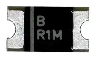
## **Features**

## **Applications**

Lead free device (RoHS compliant*) Low profile Low power loss, high efficiency UL 94V-0 classification

Lead free device (RoHS compliant*) High frequency switching power supplies Low profile Inverters Low power loss, high efficiency Free wheeling UL 94V-0 classification Polarity protection **CD1408-R1200~R11000 – Surface Mount Rectifier Diode** ~~**General Information**~~ The markets of portable communications, computing and video equipment are challenging the semiconductor industry to develop increasingly smaller electronic Tin PlatedConnectors components. Bourns offers Rectifier Diodes for rectification applications, in compact chip package 1408 size format (compatible with  SOD87, SOD123 formats), which offers PCB real estate savings and are considerably smaller than most competitive parts. The Glass Passivated Rectifier Diodes offer a forward current of 1 A with a FRP Substrate and Epoxy choice of repetitive peak reverse voltage of 200 V up to 1000 V. Underfill Bourns[®] Chip Diodes conform to JEDEC standards, are easy to handle on standard pick and place equipment and their flat configuration minimizes roll away. ~~**Electrical Characteristics (@ TA = 25 °C Unless Otherwise Noted)**~~ **CD1408Parameter Symbol Unit R1200 R1400 R1600 R1800 R11000** Maximum Repetitive Peak Reverse Voltage VRRM 200 400 600 800 1000 V Maixmum RMS Vtloage VRMS 140 280 420 560 700 V Maximum DC Blocking Voltage VDC 200 400 600 800 1000 V Max. Average Forward Rectified Current[1] I(AV) 1.0 A DC Reverse Current @ Rated DC Blocking Voltage (@Ta = 25 °C) IR 1.0 μ A DC Reverse Current @ Rated DC Blocking Voltage(@Ta = 125 °C) IR 30.0 μ A (@TDC Reverse Current @ Rated DC Blocking Voltage a = 150 °C) IR 50.0 μ A Typical Junction Capacitance[2] CJ 12 pF Instantaneous Forward Voltage @ IF = 1 A VF 1.0 V Maximum Reverse Recovery Time[3] Trr 3000 ns Peak forward surge current 8.3 ms single half sine-wave superimposed on rated load IFSM 30.0 A (JEDEC Method) Typcila Thermla Resistance Rj-a 80 °C/Watt Typcila Thermla Resistance Rl-j 40 °C/Watt Notes: 1 See Forward Derating Curve. 2 Measured @ 1.0 MHz and applied reverse voltage of 4.0 VDC. 3 Reverse recovery test condition: IF = 0.5 A, IR = 1.0 A, Irr = 0.25 A ~~**Thermal Characteristics (@ TA = 25 °C Unless Otherwise Noted)**~~ **Parameter Symbol CD1408-R1200~R11000 Unit** Operating Temperature Range TJ -65 to +175 °C Storage Temperature Range TSTG -65 to +175 °C ~~[=]~~ *RoHS Directive 2015/863, Mar 31, 2015 and Annex. **WARNING** Specifications are subject to change without notice. Users should verify actual device performance in their specific **Cancer and Reproductive Harm** applications. The products described herein and this document are subject to specific legal disclaimers as set forth on the www.P65Warnings.ca.gov last page of this document, and at www.bourns.com/docs/legal/disclaimer.pdf.

## **CD1408-R1200~R11000 – Surface Mount Rectifier Diode**

## ~~**Performance Graphs**~~

**==> picture [258 x 366] intentionally omitted <==**

**----- Start of picture text -----**<br>
Forward Current Derating Curve<br>1.50<br>1.25<br>1.00<br>0.75<br>0.50 60 Hz<br>Resistive or<br>0.25 Inductive Load<br>0<br>0 50 75 100 125 150 175 200<br>Lead Temperature (°C)<br>Typical Forward Characteristics<br>10.00<br>1.00<br>0.10<br>Pulse Width = 300 µs<br>1 % Duty Cycle<br>0.01<br>4.0 0.6 8.0 1.0 1.2 4.1 6.1<br>Instantaneous Forward Voltage (Volts)<br>Average Forward Current (Amps)<br>Instantaneous Forward Current (Amps)<br>**----- End of picture text -----**<br>


**==> picture [258 x 149] intentionally omitted <==**

**----- Start of picture text -----**<br>
Maximum Non-Repetitive Surge Current<br>30<br>25<br>20<br>15<br>Pulse Width 8.3 ms<br>10<br>Single Half Sine-Wave<br>(JEDEC Method)<br>0<br>1 10 100<br>Number of Cycles at 60 Hz<br>Peak Forward Surge Current (Amps)<br>**----- End of picture text -----**<br>


## ~~**Typical Reverse Characteristics**~~

**==> picture [210 x 193] intentionally omitted <==**

**----- Start of picture text -----**<br>
100<br>10<br>TJ = 125 °C<br>1 TJ = 100  ° C<br>0.1<br>0 20 40 60 80 100 110<br>Percent of Rated Peak Reverse Voltage (%)<br>Instantaneous Reverse Leakage Current (µA)<br>**----- End of picture text -----**<br>


## ~~**Typical Junction Capacitance**~~

**==> picture [214 x 185] intentionally omitted <==**

**----- Start of picture text -----**<br>
200<br>100<br>60<br>40<br>20<br>10<br>6<br>4<br>TJ = 25 °C<br>2<br>1<br>1.0 2.0 0.4 0.1 2 4 10 20 40 100<br>Reverse Voltage (Volts)<br>Junction Capacitance (pF)<br>**----- End of picture text -----**<br>


Specifications are subject to change without notice. Users should verify actual device performance in their specific applications. The products described herein and this document are subject to specific legal disclaimers as set forth on the last page of this document, and at www.bourns.com/docs/legal/disclaimer.pdf.

## **CD1408-R1200~R11000 – Surface Mount Rectifier Diode**

## ~~**Product Dimensions**~~

This is a lead free product, packaged with FRP substrate and is epoxy underfilled. The terminals are pure tin plated and are solderable per MIL-STD-750, Method 2026. The package weighs approximately 0.02 g. The package and dimensions are shown below.

**==> picture [233 x 176] intentionally omitted <==**

**----- Start of picture text -----**<br>
3.2 - 3.60<br>(0.126 - 0.142)<br>1.70 - 2.10 B 0.40<br>(0.067 - 0.083) (0.016)  [R]<br>R1D<br>0.50 - 0.90 0.50 - 0.90<br>(0.020 - 0.035) (0.020 - 0.035)<br>0.95 - 1.35<br>(0.037 - 0.053)<br>**----- End of picture text -----**<br>


## ~~**Recommended Footprint**~~

The device will mount onto existing JEDEC SOD-87 footprint.

## ~~**How To Order**~~

**CD  1408 - R  1  400**

Common Code CD = Chip Diode Package 1408 = ~0.14 x 0.08 ˝ Function R = Rectifier Forward Current I(AV) 1 = 1 A

Reverse Voltage 200 = 200 V 400 = 400 V 600 = 600 V 800 = 800 V 1000 = 1000 V

## ~~**Typical Part Marking**~~

CD1408-R1200 .......................................................................... **R1D** CD1408-R1400 .......................................................................... **R1G** CD1408-R1600 .......................................................................... **R1J** CD1408-R1800 .......................................................................... **R1K** CD1408-R11000 ........................................................................ **R1M**

MM DIMENSIONS: (INCHES)

Specifications are subject to change without notice. Users should verify actual device performance in their specific applications. The products described herein and this document are subject to specific legal disclaimers as set forth on the last page of this document, and at www.bourns.com/docs/legal/disclaimer.pdf.

## **CD1408-R1200~R11000 – Surface Mount Rectifier Diode**

## ~~**Packaging Information**~~

The product will be dispensed in Tape and Reel format (see diagram below).

**==> picture [270 x 191] intentionally omitted <==**

**----- Start of picture text -----**<br>
P0<br>P1 E T<br>d Index Hole<br>F<br>W<br>B<br>P A C<br>reliarT Decive Leadre<br>....... ....... ....... .......<br>End ....... ....... ....... ....... Start<br>10 pitches (min.) 10 pitches (min.)<br>Direction of Feed<br>**----- End of picture text -----**<br>


|**Item**|**Symbol**||**1408**|
|---|---|---|---|
|Carrier Width|A|(|1.85±0.1<br>0.073 ± 0.004)|
|Carrier Length|B|(|3.65 ± 0.1<br>0.144 ± 0.004)|
|Carrier Depth|C||1.25 ± 0.1<br>(0.05 ± 0.004)|
|Sprocket Hole|d|(|1.50 ± 0.1<br>0.059 ± 0.004)|
|Reel Outside Diameter|D|(|178 ± 2.0<br>7.008 ± 0.079)|
|Reel Inner Diameter|D1||50<br>(1.969) Min.|
|Feed Hole Diameter|D2|(|13.0 ± 0.5<br>0.512 ± 0.020)|
|Sprocket Hole Position|E|(|1.75 ± 0.1<br>0.069 ± 0.004)|
|Punch Hole Position|F|(|5.50 ± 0.05<br>0.217 ± 0.002)|
|Punch Hole Pitch|P|(|4.00 ± 0.1<br>0.157 ± 0.004)|
|Sprocket Hole Pitch|P0|(|4.00 ± 0.1<br>0.157 ± 0.004)|
|Embossment Center|P1|(|2.0 ± 0.1<br>0.079 ± 0.002)|
|Overall Tape Thickness|T||0.40<br>(0.016)<br>Max.|
|Tape Width|W|(|12.00±0.30<br>0.472 ± 0.012)|
|Reel Width|W1||18.7<br>(0.736) Max.|
|Quantity per Reel|—||3,000|


**==> picture [204 x 169] intentionally omitted <==**

**----- Start of picture text -----**<br>
120 °<br>D2<br>D1 D<br>W1<br>MM<br>DIMENSIONS:<br>(INCHES)<br>**----- End of picture text -----**<br>


Devices are packed in accordance with EIA standard RS-481-A and specifications shown here.

## **Asia-Pacific:**

**Europe:**

## **The Americas:**

**www.bourns.com**

## REV. 03/20

Specifications are subject to change without notice.

Users should verify actual device performance in their specific applications. The products described herein and this document are subject to specific legal disclaimers as set forth on the last page of this document, and at www.bourns.com/docs/legal/disclaimer.pdf.

®

## **Legal Disclaimer Notice**

This legal disclaimer applies to purchasers and users of Bourns[®] products manufactured by or on behalf of Bourns, Inc. and

Unless otherwise expressly indicated in writing, Bourns[®] products and data sheets relating thereto are subject to change

and complete before placing orders for Bourns[®] products.

The characteristics and parameters of a Bourns[®] product set forth in its data sheet are based on laboratory conditions, and statements regarding the suitability of products for certain types of applications are based on Bourns’ knowledge of typical requirements in generic applications.  The characteristics and parameters of a Bourns[®] product in a user application may

® product with other components ®

the actual performance of the Bourns[®]

® product as meeting the requirements of a particular industry

failure of an individual Bourns ® product to meet the requirements of such industry standard or particular qualification. Users of Bourns[®] products are responsible for ensuring compliance with safety-related requirements and standards applicable to

Bourns[®]

on a case-by-case basis, use of any Bourns[®]

®

®

®

Bourns[®]

® standard products that are suitable for use in aircraft “Applications.” Unless expressly and specifically ® standard

the user’s sole risk.

and the user for which such Bourns[®] custom and the user regarding the use and level of also apply to such Bourns[®] custom products.

® custom products shall be negotiated on a case-by-case basis by Bourns are specially designed. Absent a written agreement between Bourns testing, the above provisions applicable to Bourns ® standard products shall

Users shall not sell, transfer, export or re-export any Bourns[®]

Bourns[®]

regulations. Further, Bourns ® products and Bourns technology and technical data may not under any circumstance be exported or re-exported to countries subject to international sanctions or embargoes.  Bourns[®] products may not, without

_bilingual versions are available at:_

_Web Page: http://www.bourns.com/legal/disclaimers-terms-and-policies PDF: http://www.bourns.com/docs/Legal/disclaimer.pdf_
Updated at April 15, 2026
Bourns, Inc. is a globally recognized manufacturer of high-reliability electronic components, headquartered in Riverside, California. Renowned for its engineering excellence, the company delivers critical solutions across a diverse range of demanding markets, including automotive, industrial, consumer electronics, telecommunications, and medical equipment. The Bourns product portfolio is anchored by an industry-leading selection of passive components and circuit protection devices. The brand is particularly dominant in magnetic components, offering thousands of high-performance power inductors, alongside specialized RF and toroidal inductors engineered for optimized power management and signal integrity. Equally prominent is their comprehensive suite of circuit protection solutions. This robust lineup features a vast array of standard and resettable fuses, transient voltage suppressors (including TVS varistors and diodes), and gas discharge tubes (GDTs) designed to rigorously safeguard sensitive electronics against overvoltage and overcurrent faults. Beyond its core passives and protection technologies, Bourns manufactures highly effective EMC and RFI suppression components, such as common mode chokes and power line filters. The company's offering also extends into discrete semiconductors and power management, including Schottky diodes, fast recovery rectifiers, bridge rectifiers, and board-level transformers. This expansive breadth of quality components provides design engineers with a trusted foundation for developing resilient, efficient, and long-lasting electronic systems.
About Novapart
Novapart is a B2B electronic component broker specialising in stock shortages and cost reduction. We source hard-to-find parts and identify compliant alternatives across a catalogue of 410,000+ components from 500+ manufacturers.
Learn more →Stock Shortage Specialist
When a component is unavailable, discontinued or has an unacceptable lead time, we tap into our network of vetted European and Asian distributors to source what you need — without compromising on quality or traceability.
Request a quote →Compliant Alternatives
We identify pin-to-pin, electrically equivalent substitutes that meet the same certifications (RoHS, AEC-Q100, REACH) as your original specification — validated against datasheets, not just part numbers. Often at a lower cost.
BOM Analysis service →