
Image not available
Illustrative purposes only

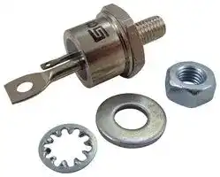
C147N
SCR Module, 800 V
⚠️ Reference pricing provided. In case of supply shortages, we will connect you with our trusted procurement partners to ensure your project's continuity.
- Manufacturer: SOLID STATE
- Product type: Thyristors - SCR Modules
- SCR Module Type: Single SCR
- Thyristor Mounting: Stud Mount
- Holding Current Max: 250mA
- On State RMS Current: 63A
- Thyristor Case Style: TO-208AC
- Gate Trigger Current Max: 150mA
- Gate Trigger Voltage Max: 3V
- Operating Temperature Max: 125°C
- Repetitive Peak Reverse Voltage: 800V
- Peak Non Repetitive Surge Current: 910A
- Peak Repetitive Off State Voltage: 800V
| Delivery and price | |
|---|---|
| Units per pack | 10 |
| Price | Ask for quotation |
| Current stock | 10+ |
| Lead time | 30 days |
Datasheet

## High Power Silicon Controlled Rectifier 1200 Volts 63A RMS

**==> picture [31 x 20] intentionally omitted <==**

**----- Start of picture text -----**<br>
C147<br>**----- End of picture text -----**<br>


C147 Silicon Controlled Rectifier is designed for phase control applications. This is an all-diffused device which is considerably smaller in size than comparably rated high power SCR’s. Fm e High dv/dt With Selections Available eee nee yan Ave faq SOUD STATE INC. e Excellent Surge and I?t Ratings, > Providing Easy Fusing | £6BLOOMFIEL FARRAN **D** , STREETNEW JERSEY 07003 www.solidstateinc.com. F e Compact, Hermetic Package, 1/4—28 Stud

## MAXIMUM ALLOWABLE RATINGS

|MAXIMUM ALLOWABLE RATINGS|MAXIMUM ALLOWABLE RATINGS|MAXIMUM ALLOWABLE RATINGS|MAXIMUM ALLOWABLE RATINGS|
|---|---|---|---|
|ee aE<br>a.<br>TYPE<br>VOLTAGE, Vpam!<br>VOLTAGE, Var!<br>REVERSE VOLTAGE, Vas!<br>Ty = -40°C to +125°C<br>T, = -40°C to +125°C<br>Ty = +125°C||||
|C147A|100 Volts|100 Volts|150 Volts|
|C147B|200|200|300|
|C147C|300|300|400|
|C147D|400|400|500|
|C147E|500|500|600|
|C147M|600|600|720|
|C1478|700|700|840|
|C147N|800|800|960|
|C147T|900|900|1080|
|C147P|1000|1000|1200|
|C147PA|1100|1100|1320|
|C147PB|1200|1200|1440|


1 Half sinewave waveform, 10 msec, maximum pulse width.

|RMS On-State Current, Iq¢ams) -- +e ee<br>ee<br>eee<br>ee eee eee ees<br>63 Amperes (AllConduction Angles)|
|---|
|Average On-State Current, Ip(ay) .--.- 22+<br>eee eee esses. Depends on Conduction Angles (See Charts 2 and 3)|
|Critical Rate-of-Rise of On-State Current (Non-Repetitive) di/dt:*|
|Switching From 1200Volts..........<br>0.0.0...eeeeeeee eeee eeeeeeee + 100Amperes<br>Per Microsecond|
|Switching From<br>600 Volts.... 2.2... .. 0... ce eee eee ee eee ee eee eee ee» 200 Amperes Per Microsecond|
|Peak One-Cycle Surge (Non-Repetitive) On-State Current, Ipsy (60 Hz): +--+ eee eee eee eee eee ees<br>+1000 Amperes|
|Peak One-Cycle Surge (Non-Repetitive) On-State Current, Ipgy (50 Hz)................-.---.--.++.-+ 910 Amperes|
|I?t (for fusing), for times> 8.3 milliseconds (See Figure 6)......................4150 (RMS Ampere)? Seconds|
|I?t (for fusing), for times> 1.5 milliseconds (See Figure 6)......................2850 (RMS Ampere)? Seconds|
|Peak Gate Power Dissipation,<br>Pgg ...-.---<br>2. eee eee eee ee eee eee ee eee ee<br>+ 100 Watts for 150 Microseconds|
|Average Gate PowerDissipati**o**n,<br>P (ay) -- +. eee<br>ete<br>eee<br>e teeter eeeeeee 2Watts<br>Storage Temperature, Tytg<br>- eee cece eee<br>ete<br>eee eee<br>e eect eee ee ees 40°C to +150°C<br>Operating Temperature, Ty... 0... ccc<br>ce ce<br>cee ee<br>eee teen cent eee neces 40°C to +125°C|
|Maximum Stud Torque ....... 0. eee<br>ee ee ee ee eee eee<br>ee eee eee ene eee<br>eee eee «30 Lb.-In.|
|3-4N-m|


> *di/dt ratings established in accordance with EIA-NEMA Standard RS-397, Section 5.2.2.6 for conditions of Vppwm stated above; 20 volts, 20 ohms gate trigger source with 0.5 sec short circuit trigger current rise time.

C147

**==> picture [511 x 597] intentionally omitted <==**

**----- Start of picture text -----**<br>
CHARACTERISTICS<br>[esr semen] on ave [wax [ows | __resteonpmmons id<br>Peak Off-State and IpRM mA Ty = -40°C to +125°C<br>Reverse Current and<br>IrRM Vprom = Vrrm =<br>cl47M p= | - | 2 | Pp<br>c1a7T p= ff 8 ee<br>C147P p- | - | 7 | ee<br>DC Gate Trigger Current lot | - | = | 150 | mAdc | Tc = 25°C, Vp = 12 Vdc, Ry = 12 Ohms<br>| - | - | 300 | Tce = -40°C, Vp = 12 Vdc, Ry = 12 Ohms<br>DC Gate Trigger Voltage Vot fF - [| - | 3 | Vde Te = 25°C, Vp = 12 Vdc, Ry = 12 Ohms<br>PF = | - | 35 | Tce = -40°C, Vp = 12 Vdc, Ry = 12 Ohms<br>| 0.25 | - | - | Te = +125°C, Rated Vppm,Ri = 1000 Ohms<br>Peak On-State Voltage VIM 3 Volts | Tc = +25°C, Ipm = 500 Amperes Peak, |<br>Millisecond Wide Pulse. Duty Cycle < 1%<br>Holding Current ly 250 mAdc | Tc = +25°C, Anode Supply = 24 Vdc,<br>Gate Supply = 10V/20 Ohms, Initia] For-<br>ward Pulse = 2 Amps., 0.1 Millisecond to<br>10 Milliseconds Wide.<br>Critical Rate-of-Rise of dv/dt 200 Volts/ | Te = +125°C, Rated Vprm, Using Linear<br>Off-State Voltage. (Higher usec Exponential Rising Waveform. Gate Open<br>values may cause device Circuited. VpRM<br>switching) Exponential dv/dt = a (.632)<br>Turn-Off Time tq 125 usec | (1) Ty = +125°C<br>(2) Ipm = 150 Amps. Peak<br>(3) Vp = 50 Volts Min.<br>(4) Vprm (Reapplied)<br>(5) Rate-of-Rise of Reapplied Off-State<br>Voltage = 20V/usec (Linear)<br>(6) Commutation di/dt = 5 A/usec<br>(7) Repetition Rate = 1: PPS.<br>(8) Gate Bias During Turn-Off Interval =<br>0 Volts, 100 Ohms<br>**----- End of picture text -----**<br>


**==> picture [529 x 699] intentionally omitted <==**

**----- Start of picture text -----**<br>
C147<br>__ 1000 ~—— rye ~150<br>_————_<br>w — — —<br>,  ”_ wt? RATING [DERIVED IFOR 2.0 |WATTS, AVERAGE GATE<br>$ 7.SSeS _ Tf] a 2 130 2,.RESISTIVE OR INDUCTIVE LOAD 50 TO 400 HZ.<br>se: | | YY: | | | | | fy,ce  eee | | | | |<br>. | w NO hae SSS ——<br>ee a S<br>o + ffc—ancTion=TewPenatuREf——fes ——j 100 a<br>ee<br>2 es 2 ee ee eeee eeee ¢ 90eee<br>A 0a | |<br>2 80<br>g | ff | [| [| [| | | Mn.<br>5 or y 190°<br>Y x CONDUCTION ANGLE<br>: 10) 0 INSTANTANEOUS20 ON-30  STATE40VOLTAGE 50(VOLTS 60) 70 rt= 60 ° 10 AVERAGELILON-UtSTATE CURRENT| (AMPERES ~°||70<br>1. MAXIMUM ON-STATE CHARACTERISTICS 2. MAXIMUM ALLOWABLE CASE TEMPERATURE<br>FOR SINUSOIDAL CURRENT WAVEFORM<br>a<br>~150 —<br>~<br>°w 60 | |.“MAXIMUM RATINGPOWER |DISSIPATION.[DERIVEDRATE OF|FORRISE2.0 OFWATTSi ON- STATEAVERAGE| CURRENT=GATE| eee=80E ~__ |B-MAXIMUM| RATINGSGATE POWER DERIVEDRATE”DISSIPATION. IFOROFRISE2.0 OFWATTS| ON- STATEAVERAGE| oc<br>Fs 20 AMP/ MICROSECOND di/dt. > CURRENT<br>E 130 B. 50-400 HZ. S70 JUNCTION = 20TEMPERATURE AMPS/ MICROSECOND.= + 125°C. Ji<br>2£12005 a== ®& 60 ioe A<br>"ol SS | | && |lwo]50 |<br>7) Noa—— eS » 5c | J<br>< 90 e MLL |<br>zzett80 EES —|120 50 YWty Y-V7 | M<br>2z [70] | LE EL t ; now 10 a Ae eeeLo<br>609 10 20 30 40 50 60 70 z °o 10 20 30 40 50 60 70<br>AVERAGE ON- STATE CURRENT (AMPERES) AVERAGE ON- STATE CURRENT (AMPERES)<br>3. MAXIMUM ALLOWABLE CASE TEMPERATURE 4. MAXIMUM ON-STATE POWER DISSIPATION FOR<br>FOR RECTANGULAR CURRENT WAVEFORM SINUSOIDAL CURRENT WAVEFORM<br>#90g |.RATINGS DERIVED FOR 2.0 WATTS AVERAGE<br>= 80 2° GATEMAXIMUM~RATEPOWER DISSIPATION,|OF “RISE “OF ON= STATE”| CURRENT<br>S702 . 20JUNCTION—T EMPERATURE:AMP/ MICROSECONDS 5%<br>(=)ri an s000<br>; 97<br>& 40 fpury cycle: 8.3% a | | | a|.<br>=i 30 Y z=z<br>“OFtc | tm ml i<br>y 10 A,wy| pd1991*% OUTY CYCLE £:~~<br>z 10 20 30 40 50 60 70 2000; 2 3 4 5 6 7 6 9 10<br>AVERAGE ON- STATE CURRENT (AMPERES) PULSE WIDTH~ MILLISECONDS<br>5, MAXIMUM ON-STATE POWER DISSIPATION FOR 1? RATING FOLLOWING RATED LOAD CONDITIONS<br>RECTANGULAR CURRENT WAVEFORM 6. MAXIMUM ALLOWABLE NON-REPETITIVE<br>SURGE CURRENT<br>**----- End of picture text -----**<br>


**==> picture [504 x 480] intentionally omitted <==**

**----- Start of picture text -----**<br>
C147<br>50 a ee<br>5 4030ENv, )y cle2  SE2<br>5€ okt NUNe EXo|ANT% * eaorcSEETo winsre w COTMCn<br>ede ocala ST<br>e aerection| TITTT: CoeSaaS eaeeri<br>7 L— 20v, 20a 4<br>Lbs<br>' (I/II LAI EEREoo or 1 an1 fT<br>2 INSTANTANEOUS Gate CURRENT. AMPERES TIME (SECONDS)<br>7. GATE TRIGGER CHARACTERISTICS AND 8 TRANSIENT THERMAL IMPEDANCE —<br>POWER RATINGS JUNCTION-TO-CASE<br>. CASE STYLE AND DIMENSIONS an 2.26 (0.089) MAX. (0.089) MAX. MAX.<br>MAX, 1.830.072)<br>7710.06) D!A.<br>,px \—— 16.94DIA. MAX.(0.667)DIA. MAX.(0.667) MAX.(0.667)(0.667) BETODTH6.321/4-28UNF-2A(0.2436.321/4-28UNF-2A(0.2431/4-28UNF-2A(0.243(0.243  OA<br>one 3.56 (0,140)<br>heata 2.54(0.100)(0.100) 7 il/ 7/ 7 7 17.35 (0.683)<br>a 3093 ~ be2o300 f toi saa 17.20<br>14.35 cet. = MAX.<br>MAX.(0.565) aFAM123 Wikia"ys p 3.580.141)333(0.131)333(0.131) 0. i 11.43 (0.450)10.80 (0.425)10.80 (0.425) (0.425)<br>+ SS—os yl aos§.08§.08 (0.200078)078)<br>a : oe‘fv aati 14.35 (0.565) (0.565)<br>MAX.<br>“ ~~ 30.93 (1.218) (1.218) MAX.<br>1/4-2BUNF-2A Conforms to JEDEC to JEDEC JEDEC : TO—208AC TO—208AC (TO-65)<br>**----- End of picture text -----**<br>


**==> picture [265 x 207] intentionally omitted <==**

**----- Start of picture text -----**<br>
an 2.26 (0.089) MAX. (0.089) MAX. MAX.<br>MAX, 1.830.072)<br>7710.06) D!A.<br>16.94DIA. MAX.(0.667)DIA. MAX.(0.667) MAX.(0.667)(0.667) BETODTH6.321/4-28UNF-2A(0.2436.321/4-28UNF-2A(0.2431/4-28UNF-2A(0.243(0.243  OA<br>3.56 (0,140)<br>2.54(0.100)(0.100) 7 il/ 7/ 7 7 17.35 (0.683)<br>~ be2o300 f toi saa 17.20 (0.677)<br>3.580.141)333(0.131)333(0.131) 0. i 11.43 (0.450)10.80 (0.425)10.80 (0.425) (0.425)<br>aos§.08§.08 (0.200078)078)<br>aati 14.35 (0.565) (0.565)<br>MAX.<br>30.93 (1.218) (1.218) MAX.<br>Conforms to JEDEC to JEDEC JEDEC : TO—208AC TO—208AC (TO-65)<br>**----- End of picture text -----**<br>


All Dimensions in Millimeters and (Inches)
Updated at February 9, 2023
About Novapart
Novapart is a B2B electronic component broker specialising in stock shortages and cost reduction. We source hard-to-find parts and identify compliant alternatives across a catalogue of 410,000+ components from 500+ manufacturers.
Learn more →Stock Shortage Specialist
When a component is unavailable, discontinued or has an unacceptable lead time, we tap into our network of vetted European and Asian distributors to source what you need — without compromising on quality or traceability.
Request a quote →Compliant Alternatives
We identify pin-to-pin, electrically equivalent substitutes that meet the same certifications (RoHS, AEC-Q100, REACH) as your original specification — validated against datasheets, not just part numbers. Often at a lower cost.
BOM Analysis service →