
Image not available
Illustrative purposes only

BUJ302AD,118
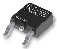
Bipolar (BJT) Single Transistor, NPN, 400 V, 4 A, 80 W, TO-252 (DPAK), Surface Mount
⚠️ Reference pricing provided. In case of supply shortages, we will connect you with our trusted procurement partners to ensure your project's continuity.
- Manufacturer: WEEN SEMICONDUCTORS
- Product type:
- Transistor Polarity:NPN; Collector Emitter Voltage V(br)ceo:400V; Transition Frequency ft:-; Power Dissipation Pd:80W; DC Collector Current:4A; DC Current Gain hFE:66hFE; Transistor Case
- MSL: MSL 1 - Unlimited
- SVHC: Lead (23-Jan-2024)
- No. of Pins: 3Pins
- Product Range: -
- Qualification: -
- Power Dissipation: 80W
- Transistor Mounting: Surface Mount
- Transistor Polarity: NPN
- Transition Frequency: -
- Transistor Case Style: TO-252 (DPAK)
- DC Current Gain hFE Min: 66hFE
- Operating Temperature Max: 150°C
- Continuous Collector Current: 4A
- Collector Emitter Voltage Max: 400V
| Delivery and price | |
|---|---|
| Units per pack | 7500 |
| Price | 0.185 € |
| Current stock | 10+ |
| Lead time | 30 days |
Datasheet

**10 December 2015**

**==> picture [49 x 66] intentionally omitted <==**

## **IMPORTANT NOTICE**

## **1.  Global joint venture starts operations as WeEn Semiconductors**

Dear customer,

As from November 9th, 2015 NXP Semiconductors N.V. and Beijing JianGuang Asset Management Co. Ltd established Bipolar Power joint venture (JV), **WeEn Semiconductors** , which will be used in future Bipolar Power documents together with new contact details.

In this document where the previous NXP references remain, please use the new links as shown below.

**WWW** - For www.nxp.com use www.ween-semi.com **Email** - For salesaddresses@nxp.com use salesaddresses@ween-semi.com

For the copyright notice at the bottom of each page (or elsewhere in the document, depending on the version) “[©] **NXP Semiconductors N.V.** _**{year}**_ **. All rights reserved** ” becomes “[©] **WeEn Semiconductors Co., Ltd.** _**{year}**_ **. All rights reserved** ”

If you have any questions related to this document, please contact our nearest sales office via e- mail or phone (details via salesaddresses@ween-semi.com).

Thank you for your cooperation and understanding,

WeEn Semiconductors

**==> picture [52 x 41] intentionally omitted <==**

## **BUJ302AD NPN power transistor Rev. 01 — 28 March 2011 Product data sheet** a“ | ~~ee~~

## **1. Product profile**

## **1.1 General description**

High-voltage, high-speed planar-passivated NPN power switching transistor in a SOT428 (DPAK) surface mounted package.

## **1.2 Features and benefits**

Fast switching High voltage capability

Low thermal resistance Surface-mountable package

## **1.3 Applications**

DC-to-DC converters

High-frequency electronic lighting ballast applications

Inverters

Motor control systems

## **1.4 Quick reference data**

|**Table 1.**|**Quick reference data**|||||||||
|---|---|---|---|---|---|---|---|---|---|
|**Symbol**|**Parameter**|**Conditions**||||**Min**|**Typ**|**Max**|**Unit**|
|IC|collector current|seeFigure 1<br>;see Figure 2<br>;||||-|-|4|A|
|||seeFigure 4||||||||
|||||||||||
|Ptot|total power dissipation|Tmb≤25 °C; see|≤25 °C; see Figure 3|||-|-|80|W|
|VCESM|collector-emitter peak|VBE= 0 V||||-|-|1050|V|
||voltage|||||||||
|**Static characteristics**||||||||||
|hFE|DC current gain|IC= 0.1 A; VCE= 5 V;|||[1]|48|66|100||
|||Tmb= 25 °C; see Figure 11||||||||
|||||||||||
|||IC= 0.8 A; VCE= 3 V;|||[1]|25|42|50||
|||Tmb= 25 °C; see Figure 12||||||||


- [1] Pulse test: pulse duration ≤ 300 µs, duty cycle ≤ 2 %

**BUJ302AD**

**NXP Semiconductors**

**NPN power transistor**

## **2. Pinning information**

## **Table 2. Pinning information**

|**Pin**|**Symbol**|**Description**|**Simplified outline**|**Simplified outline**|**Simplified outline**|**Simplified outline**|**Simplified outline**|**Simplified outline**|||**Graphic symbol**|**Graphic symbol**||
|---|---|---|---|---|---|---|---|---|---|---|---|---|---|
|1<br>2|B<br>C|base<br>collector[1]||||mb|||||||C|
|3|E|emitter|||||||||B|||
|mb|C|mounting base; connected to||||||||||||
|||collector|||||||||||E|
|||||||1|2|3||||_sym123_||
||||**SOT428 (DPAK)**|||||||||||


[1] it is not possible to make a connection to pin 2 of the SOT428 (DPAK) package

## **3. Ordering information**

## **Table 3. Ordering information**

|**Type number**|**Package**|
|---|---|
||**Name**<br>**Description**<br>**Version**|
|BUJ302AD|DPAK<br>plastic single-ended surface-mounted package (DPAK); 3 leads<br>(one lead cropped)<br>SOT428|


## **4. Limiting values**

**Table 4. Limiting values**

_In accordance with the Absolute Maximum Rating System (IEC 60134)._

|**Symbol**<br>**Parameter**<br>**Conditions**|**Min**<br>**Max**<br>**Unit**|
|---|---|
|VCESM<br>collector-emitter peak voltage<br>VBE= 0 V|-<br>1050<br>V|
|VCEO<br>collector-emitter voltage<br>IB= 0 A|-<br>400<br>V|
|IC<br>collector current<br>see Figure 1<br>;see Figure 2<br>;see Figure 4<br>ICM<br>peak collector current|-<br>4<br>A|
||-<br>8<br>A|
|IB<br>base current|-<br>2<br>A|
|IBM<br>peak base current|-<br>4<br>A|
|Ptot<br>total power dissipation<br>Tmb≤25 °C; seeFigure 3|-<br>80<br>W|
|Tstg<br>storage temperature|-65<br>150<br>°C|
|Tj<br>junction temperature|-<br>150<br>°C|
|VEBO<br>emitter-base voltage<br>IC= 0 A; IE= 2 A; tp< 10 ms|-<br>24<br>V|


© NXP B.V. 2011. All rights reserved.

All information provided in this document is subject to legal disclaimers.

BUJ302AD

**Product data sheet**

**Rev. 01 — 28 March 2011**

**2 of 14**

**BUJ302AD**

**NXP Semiconductors**

## **NPN power transistor**

**==> picture [425 x 187] intentionally omitted <==**

**----- Start of picture text -----**<br>
10 003aag027 VCC<br>IC<br>(A) PTT ETT [TTT] LC VCL(CE)<br>8 PT TTT [TTT] yy probe point<br>PTT ATT TT TTEy yy IBon 7 LB<br>DUT<br>6 BERNER VBB =<br>001aab999<br>4 shiinentePTT Ty TAALNI Vercmy=< 1000 THsV: Vee = 150Vi Vp, = —5<br>2 PtPTTTTT TT TTPay Le =200 pil<br>0 PT TET TTTTET T T TT<br>0 400 800 1200<br>VCEclamp (V)<br>**----- End of picture text -----**<br>


**Fig 1. Reverse bias safe operating area Fig 2. Test circuit for reverse bias safe operating area**

**==> picture [190 x 186] intentionally omitted <==**

**----- Start of picture text -----**<br>
001aab993<br>120<br>Pder<br>(%)80 EINEUNE\<br>\<br>40 EELENNEL\<br>\<br>0 EEELEETEEDA\<br>0 40 80 120 160<br>Tmb (°C)<br>**----- End of picture text -----**<br>


**Fig 3. Normalized total power dissipation as a function of mounting base temperature**

© NXP B.V. 2011. All rights reserved.

All information provided in this document is subject to legal disclaimers.

BUJ302AD

**Product data sheet**

**Rev. 01 — 28 March 2011**

**3 of 14**

**BUJ302AD**

**NXP Semiconductors**

**NPN power transistor**

**==> picture [481 x 189] intentionally omitted <==**

**----- Start of picture text -----**<br>
001aac001<br>10 [2]<br>IC<br>(A)<br>10 duty cycle = 0.01<br>ICM(max)<br>IC(max) II(3) tp = 20 μs<br>(1)<br>1 50 μs<br>100 μs<br>200 μs<br>(2)<br>500 μs<br>10 [−][1]<br>DC<br>I(3)<br>10 [−][2]<br>III(3)<br>10 [−][3]<br>1 10 10 [2] 10 [3]<br>VCEclamp (V)<br>**----- End of picture text -----**<br>


1)Ptot maximum and Ptot peak maximum lines

2)Second breakdown limits

3) I = Region of permissable DC operation

II = Extension for repetitive pulse operation

III = Extension during turn-on in single transistor converters provided that RBE ≤ 100 Ω and tp ≤ 0.6 μs

**Fig 4. Forward bias safe operating area for Tmb ≤ 25 °C**

© NXP B.V. 2011. All rights reserved.

All information provided in this document is subject to legal disclaimers.

BUJ302AD

**Product data sheet**

**Rev. 01 — 28 March 2011**

**4 of 14**

**BUJ302AD**

**NXP Semiconductors**

**NPN power transistor**

## **5. Thermal characteristics**

**==> picture [497 x 306] intentionally omitted <==**

**----- Start of picture text -----**<br>
Table 5. Thermal characteristics<br>Symbol Parameter Conditions Min Typ Max Unit<br>Rth(j-mb) thermal resistance from junction to  see Figure 5 - - 1.56 K/W<br>mounting base<br>Rth(j-a) thermal resistance from junction to ambient in free air - 60 - K/W<br>001aab998<br>10<br>Zth(j-mb)<br>(K/W)<br>1 δ = 0.5<br>0.2<br>0.1<br>0.050.02 Ptot δ = Ttp<br>10 [−][1]<br>0.01<br>tp t<br>T<br>10 [−][2]<br>10 [−][5] 10 [−][4] 10 [−][3] 10 [−][2] 10 [−][1] 1 10<br>tp (s)<br>Fig 5. Transient thermal impedance from junction to mounting base as a function of pulse width<br>**----- End of picture text -----**<br>


© NXP B.V. 2011. All rights reserved.

All information provided in this document is subject to legal disclaimers.

BUJ302AD

**Product data sheet**

**Rev. 01 — 28 March 2011**

**5 of 14**

**BUJ302AD NPN power transistor**

**NXP Semiconductors**

## **6. Characteristics**

|**Table 6.**<br>**Characteristics**|||
|---|---|---|
|**Symbol**<br>**Parameter**|**Conditions**|**Min**<br>**Typ**<br>**Max**<br>**Unit**|
|**Static characteristics**|||
|ICES<br>collector-emitter cut-off<br>current|VBE= 0 V; VCE= 1050 V; Tmb= 25 °C|-<br>0.2<br>10<br>µA|
|ICEO<br>collector-emitter cut-off<br>current|VCE= 400 V; IB= 0 A; Tmb= 25 °C|-<br>10<br>250<br>mA|
|V(BR)EBO<br>open-collector emitter-base<br>breakdown voltage|IB= 1 mA; IC= 0 A; Tmb= 25 °C|15<br>19<br>-<br>V|
|VCEOsus<br>collector-emitter sustaining<br>voltage|IB= 0 A; IC= 10 mA; LC= 25 mH;<br>Tmb= 25 °C; see Figure 6<br>;<br>seeFigure 7|[1]<br>400<br>470<br>-<br>V|
|VCEsat<br>collector-emitter saturation<br>voltage|IC= 1 A; IB= 0.2 A; Tmb= 25 °C;<br>seeFigure 8<br>;see Figure 9|[1]<br>-<br>0.15<br>0.5<br>V|
||IC= 3.5 A; IB= 1 A; Tmb= 25 °C;<br>seeFigure 8<br>;see Figure 9|[1]<br>-<br>0.6<br>1.5<br>V|
|VBEsat<br>base-emitter saturation<br>voltage|IC= 3.5 A; IB= 1 A; Tmb= 25 °C;<br>seeFigure 10|[1]<br>-<br>1.1<br>1.5<br>V|
|hFE<br>DC current gain|IC= 0.1 A; VCE= 5 V; Tmb= 25 °C;<br>seeFigure 11|[1]<br>48<br>66<br>100|
||IC= 0.8 A; VCE= 3 V; Tmb= 25 °C;<br>seeFigure 12|[1]<br>25<br>42<br>50|
|**Dynamic characteristics**|||
|ts<br>storage time|IC= 2.5 A; IBon= 0.5 A; IBoff= -0.5 A;<br>RL= 60 Ω; VBB= -5 V; Tmb= 25 °C;<br>resistive load; tp= 300 µs;<br>seeFigure 13<br>;seeFigure 14|-<br>-<br>3.5<br>µs|
|tf<br>fall time||-<br>-<br>500<br>ns|


[1] Pulse test: pulse duration ≤ 300 µs, duty cycle ≤ 2 %

**==> picture [497 x 217] intentionally omitted <==**

**----- Start of picture text -----**<br>
50 V IC<br>100 Ω to 200 Ω (mA)<br>horizontal<br>oscilloscope<br>vertical 250<br>6 V<br>300 Ω 1 Ω<br>100<br>30 Hz to 60 Hz<br>001aab987<br>10<br>0<br>min VCE (V)<br>VCEOsus<br>001aab988<br>Fig 6. Test circuit for collector-emitter sustaining  Fig 7. Oscilloscope display for collector-emitter<br>voltage sustaining voltage test waveform<br>**----- End of picture text -----**<br>


All information provided in this document is subject to legal disclaimers.

© NXP B.V. 2011. All rights reserved.

BUJ302AD **Product data sheet**

**Rev. 01 — 28 March 2011**

**6 of 14**

**BUJ302AD**

**NXP Semiconductors**

## **NPN power transistor**

**==> picture [439 x 186] intentionally omitted <==**

**----- Start of picture text -----**<br>
003aaf994 003aaf996<br>10 6<br>1.4 A<br>VCEsat IC 1.2 A<br>(V) (A) 1.0 A<br>I See<br>0.8 A<br>1 IE TUT 4 {a 0.6 A<br>0.4 A<br>Tj = 125 °C<br>Set A, | = ae<br>IB = 0.2 A<br>10 [-1] | ante Tj = 25 °C  cat 2 ZPer ae<br>10 [-2] CCCn e 0 CEEryeerEeeSL I<br>10 [-2] 10 [-1] 1 10 0 2 4 6 8 10<br>IC (A) VCE (V)<br>**----- End of picture text -----**<br>


**Fig 8. Collector-emitter saturation voltage as a function of collector current; typical values**

**Fig 9. Collector current as a function of collector-emitter voltage; typical values**

**==> picture [439 x 185] intentionally omitted <==**

**----- Start of picture text -----**<br>
003aaf993 003aaf992<br>1.2 10 [2]<br>VBEsat VCE = 5 V<br>(V)<br>1.0 hFE<br>Tj = 25 °C<br>Tj = 25 °C<br>0.8 H i Tj = 125 °C  \<br>10<br>0.6 CTTI e Tj = 125 °C  THMA CTI,culANal<br>aq Sete<br>0.4<br>0.2 ST 1 UNI<br>10 [-2] 10 [-1] 1 10 10 [-2] 10 [-1] EAE 1 10<br>IC (A) IC (A)<br>**----- End of picture text -----**<br>


**Fig 10. Base-emitter saturation voltage as a function of collector current; typical values**

- **Fig 11. DC current gain as a function of collector current; typical values**

© NXP B.V. 2011. All rights reserved.

All information provided in this document is subject to legal disclaimers.

BUJ302AD

**Product data sheet**

**Rev. 01 — 28 March 2011**

**7 of 14**

**BUJ302AD**

**NXP Semiconductors**

## **NPN power transistor**

**==> picture [409 x 186] intentionally omitted <==**

**----- Start of picture text -----**<br>
10 [2] a OO OO GG 0 003aaf991 VCC<br>SSPN S VCE = 3 V [|<br>hFE aLt TTPENNEENN Tj TT  = 25 °C  VIM0 RB DUTRL<br>HHETAT EALET T  TTT| {t- f<br>Tj = 125 °C  tp<br>10 Mc ANIM +E T<br>ee cee Wee 001aab989<br>ee A<br>ed ee ae a<br>A ie 88 Voc =<br>a a lll R, and R, calculated from I,,,,and I;,,,<br>1<br>10 [-2] 10 [-1] 1 10<br>IC (A)<br>**----- End of picture text -----**<br>


**Fig 12. DC current gain as a function of collector current; typical values**

**Fig 13. Test circuit for resistive load switching**

**==> picture [215 x 187] intentionally omitted <==**

**----- Start of picture text -----**<br>
IC<br>ICon<br>90 % 90 %<br>10 %<br>t<br>tf<br>IB ts<br>ton toff<br>IBon<br>10 %<br>t<br>tr ≤ 30 ns<br>−IBoff<br>001aab990<br>**----- End of picture text -----**<br>


**Fig 14. Switching times waveforms for resistive load**

© NXP B.V. 2011. All rights reserved.

All information provided in this document is subject to legal disclaimers.

BUJ302AD

**Product data sheet**

**Rev. 01 — 28 March 2011**

**8 of 14**

**BUJ302AD**

**NXP Semiconductors**

**NPN power transistor**

## **7. Package outline**

**==> picture [480 x 8] intentionally omitted <==**

**----- Start of picture text -----**<br>
Plastic single-ended surface-mounted package (DPAK); 3 leads (one lead cropped)  SOT428<br>**----- End of picture text -----**<br>


**==> picture [481 x 565] intentionally omitted <==**

**----- Start of picture text -----**<br>
y<br>E A A<br>b2 A1 E1<br>mounting<br>base D2<br>D1<br>HD<br>2<br>L2 L<br>1 3 L1<br>b1 b w M A c<br>e<br>e1<br>0 5 10 mm<br>scale<br>DIMENSIONS (mm are the original dimensions)<br>UNIT A A1 b b1 b2 c D1 minD2 E minE1 e e1 HD L minL1 L2 w maxy<br>2.38 0.93 0.89 1.1 5.46 0.56 6.22 6.73 10.4 2.95 0.9<br>mm 4.0 4.45 2.285 4.57 0.5 0.2 0.2<br>2.22 0.46 0.71 0.9 5.00 0.20 5.98 6.47 9.6 2.55 0.5<br>OUTLINE REFERENCES EUROPEAN<br>ISSUE DATE<br>VERSION IEC JEDEC JEITA PROJECTION<br>06-02-14<br>SOT428 TO-252 SC-63<br>06-03-16<br>**----- End of picture text -----**<br>


**Fig 15. Package outline SOT428 (DPAK)**

All information provided in this document is subject to legal disclaimers.

© NXP B.V. 2011. All rights reserved.

BUJ302AD

**Product data sheet**

**Rev. 01 — 28 March 2011**

**9 of 14**

**BUJ302AD**

**NXP Semiconductors**

**NPN power transistor**

## **8. Soldering**

**==> picture [255 x 311] intentionally omitted <==**

**----- Start of picture text -----**<br>
7.00<br>6.15<br>5.90<br>5.80<br>1.80<br>1.00<br>4.60 4.725<br>5.75 5.65<br>6.50<br>1.15<br>3.60<br>6.00<br>2.45<br>6.00 6.125<br>2.40 2.30 0.30<br>1.50 1.30<br>solder lands 1.40<br>1.65<br>solder resist 4.57<br>SOT428<br>occupied area<br>solder paste<br>**----- End of picture text -----**<br>


**Fig 16. Reflow soldering footprint for SOT428 (DPAK)**

© NXP B.V. 2011. All rights reserved.

All information provided in this document is subject to legal disclaimers.

BUJ302AD

**Product data sheet**

**Rev. 01 — 28 March 2011**

**10 of 14**

**BUJ302AD**

**NXP Semiconductors**

**NPN power transistor**

## **9. Revision history**

|**Table 7.**|**Revision**|**history**||||
|---|---|---|---|---|---|
|**Document**|**ID**|**Release date**|**Data sheet status**|**Change notice**|**Supersedes**|
|BUJ302AD|v.1|20110328|Product data sheet|-|-|


© NXP B.V. 2011. All rights reserved.

All information provided in this document is subject to legal disclaimers.

BUJ302AD

**Product data sheet**

**Rev. 01 — 28 March 2011**

**11 of 14**

**BUJ302AD NPN power transistor**

**NXP Semiconductors**

## **10. Legal information**

## **10.1 Data sheet status**

|**Document status[1]**<br> **[2]**|**Product status[3]**|**Definition**|
|---|---|---|
|Objective [short] data sheet|Development|This document contains data from the objective specification for product development.|
|Preliminary [short] data sheet|Qualification|This document contains data from the preliminary specification.|
|Product [short] data sheet|Production|This document contains the product specification.|


[1] Please consult the most recently issued document before initiating or completing a design.

[2] The term 'short data sheet' is explained in section "Definitions".

[3] The product status of device(s) described in this document may have changed since this document was published and may differ in case of multiple devices. The latest product status information is available on the Internet at URL http://www.nxp.com.

## **10.2 Definitions**

**Draft** — The document is a draft version only. The content is still under internal review and subject to formal approval, which may result in modifications or additions. NXP Semiconductors does not give any representations or warranties as to the accuracy or completeness of information included herein and shall have no liability for the consequences of use of such information.

**Short data sheet** — A short data sheet is an extract from a full data sheet with the same product type number(s) and title. A short data sheet is intended for quick reference only and should not be relied upon to contain detailed and full information. For detailed and full information see the relevant full data sheet, which is available on request via the local NXP Semiconductors sales office. In case of any inconsistency or conflict with the short data sheet, the full data sheet shall prevail.

**Product specification** — The information and data provided in a Product data sheet shall define the specification of the product as agreed between NXP Semiconductors and its customer, unless NXP Semiconductors and customer have explicitly agreed otherwise in writing. In no event however, shall an agreement be valid in which the NXP Semiconductors product is deemed to offer functions and qualities beyond those described in the Product data sheet.

## **10.3 Disclaimers**

**Limited warranty and liability** — Information in this document is believed to be accurate and reliable. However, NXP Semiconductors does not give any representations or warranties, expressed or implied, as to the accuracy or completeness of such information and shall have no liability for the consequences of use of such information.

In no event shall NXP Semiconductors be liable for any indirect, incidental, punitive, special or consequential damages (including - without limitation - lost profits, lost savings, business interruption, costs related to the removal or replacement of any products or rework charges) whether or not such damages are based on tort (including negligence), warranty, breach of contract or any other legal theory.

Notwithstanding any damages that customer might incur for any reason whatsoever, NXP Semiconductors’ aggregate and cumulative liability towards customer for the products described herein shall be limited in accordance with the _Terms and conditions of commercial sale_ of NXP Semiconductors.

**Right to make changes** — NXP Semiconductors reserves the right to make changes to information published in this document, including without limitation specifications and product descriptions, at any time and without notice. This document supersedes and replaces all information supplied prior to the publication hereof.

**Suitability for use** — NXP Semiconductors products are not designed, authorized or warranted to be suitable for use in life support, life-critical or safety-critical systems or equipment, nor in applications where failure or malfunction of an NXP Semiconductors product can reasonably be expected to result in personal injury, death or severe property or environmental damage. NXP Semiconductors accepts no liability for inclusion and/or use of NXP Semiconductors products in such equipment or applications and therefore such inclusion and/or use is at the customer’s own risk.

**Quick reference data** — The Quick reference data is an extract of the product data given in the Limiting values and Characteristics sections of this document, and as such is not complete, exhaustive or legally binding.

**Applications** — Applications that are described herein for any of these products are for illustrative purposes only. NXP Semiconductors makes no representation or warranty that such applications will be suitable for the specified use without further testing or modification.

Customers are responsible for the design and operation of their applications and products using NXP Semiconductors products, and NXP Semiconductors accepts no liability for any assistance with applications or customer product design. It is customer’s sole responsibility to determine whether the NXP Semiconductors product is suitable and fit for the customer’s applications and products planned, as well as for the planned application and use of customer’s third party customer(s). Customers should provide appropriate design and operating safeguards to minimize the risks associated with their applications and products.

NXP Semiconductors does not accept any liability related to any default, damage, costs or problem which is based on any weakness or default in the customer’s applications or products, or the application or use by customer’s third party customer(s). Customer is responsible for doing all necessary testing for the customer’s applications and products using NXP Semiconductors products in order to avoid a default of the applications and the products or of the application or use by customer’s third party customer(s). NXP does not accept any liability in this respect.

**Limiting values** — Stress above one or more limiting values (as defined in the Absolute Maximum Ratings System of IEC 60134) will cause permanent damage to the device. Limiting values are stress ratings only and (proper) operation of the device at these or any other conditions above those given in the Recommended operating conditions section (if present) or the Characteristics sections of this document is not warranted. Constant or repeated exposure to limiting values will permanently and irreversibly affect the quality and reliability of the device.

**Terms and conditions of commercial sale** — NXP Semiconductors products are sold subject to the general terms and conditions of commercial sale, as published at http://www.nxp.com/profile/terms, unless otherwise agreed in a valid written individual agreement. In case an individual agreement is concluded only the terms and conditions of the respective

© NXP B.V. 2011. All rights reserved.

All information provided in this document is subject to legal disclaimers.

BUJ302AD

**Product data sheet**

**Rev. 01 — 28 March 2011**

**12 of 14**

**BUJ302AD**

**NXP Semiconductors**

**NPN power transistor**

agreement shall apply. NXP Semiconductors hereby expressly objects to applying the customer’s general terms and conditions with regard to the purchase of NXP Semiconductors products by customer.

**No offer to sell or license** — Nothing in this document may be interpreted or construed as an offer to sell products that is open for acceptance or the grant, conveyance or implication of any license under any copyrights, patents or other industrial or intellectual property rights.

**Export control** — This document as well as the item(s) described herein may be subject to export control regulations. Export might require a prior authorization from national authorities.

**Non-automotive qualified products** — Unless this data sheet expressly states that this specific NXP Semiconductors product is automotive qualified, the product is not suitable for automotive use. It is neither qualified nor tested in accordance with automotive testing or application requirements. NXP Semiconductors accepts no liability for inclusion and/or use of non-automotive qualified products in automotive equipment or applications.

In the event that customer uses the product for design-in and use in automotive applications to automotive specifications and standards, customer (a) shall use the product without NXP Semiconductors’ warranty of the

product for such automotive applications, use and specifications, and (b) whenever customer uses the product for automotive applications beyond NXP Semiconductors’ specifications such use shall be solely at customer’s own risk, and (c) customer fully indemnifies NXP Semiconductors for any liability, damages or failed product claims resulting from customer design and use of the product for automotive applications beyond NXP Semiconductors’ standard warranty and NXP Semiconductors’ product specifications.

## **10.4 Trademarks**

Notice: All referenced brands, product names, service names and trademarks are the property of their respective owners.

**Adelante** , **Bitport** , **Bitsound** , **CoolFlux** , **CoReUse** , **DESFire** , **EZ-HV** , **FabKey** , **GreenChip** , **HiPerSmart** , **HITAG** , **I²C-bus** logo, **ICODE** , **I-CODE** , **ITEC** , **Labelution** , **MIFARE** , **MIFARE Plus** , **MIFARE Ultralight** , **MoReUse** , **QLPAK** , **Silicon Tuner** , **SiliconMAX** , **SmartXA** , **STARplug** , **TOPFET** , **TrenchMOS** , **TriMedia** and **UCODE** — are trademarks of NXP B.V.

**HD Radio** and **HD Radio** logo — are trademarks of iBiquity Digital Corporation.

## **11. Contact information**

For more information, please visit: http://www.nxp.com

For sales office addresses, please send an email to: salesaddresses@nxp.com

© NXP B.V. 2011. All rights reserved.

All information provided in this document is subject to legal disclaimers.

BUJ302AD

**Product data sheet**

**Rev. 01 — 28 March 2011**

**13 of 14**

**BUJ302AD**

**NXP Semiconductors**

**NPN power transistor**

## **12. Contents**

|**1**|**Product profile . . . . . . . . . . . . . . . . . . . . . . . . . . .1**|
|---|---|
|1.1|General description  . . . . . . . . . . . . . . . . . . . . . .1|
|1.2|Features and benefits. . . . . . . . . . . . . . . . . . . . .1|
|1.3|Applications  . . . . . . . . . . . . . . . . . . . . . . . . . . . .1|
|1.4|Quick reference data  . . . . . . . . . . . . . . . . . . . . .1|
|**2**|**Pinning information. . . . . . . . . . . . . . . . . . . . . . .2**|
|**3**|**Ordering information. . . . . . . . . . . . . . . . . . . . . .2**|
|**4**|**Limiting values. . . . . . . . . . . . . . . . . . . . . . . . . . .2**|
|**5**|**Thermal characteristics  . . . . . . . . . . . . . . . . . . .5**|
|**6**|**Characteristics. . . . . . . . . . . . . . . . . . . . . . . . . . .6**|
|**7**|**Package outline . . . . . . . . . . . . . . . . . . . . . . . . . .9**|
|**8**|**Soldering  . . . . . . . . . . . . . . . . . . . . . . . . . . . . . .10**|
|**9**|**Revision history. . . . . . . . . . . . . . . . . . . . . . . . .11**|
|**10**|**Legal information. . . . . . . . . . . . . . . . . . . . . . . .12**|
|10.1|Data sheet status . . . . . . . . . . . . . . . . . . . . . . .12|
|10.2|Definitions. . . . . . . . . . . . . . . . . . . . . . . . . . . . .12|
|10.3|Disclaimers . . . . . . . . . . . . . . . . . . . . . . . . . . . .12|
|10.4|Trademarks. . . . . . . . . . . . . . . . . . . . . . . . . . . .13|
|**11**|**Contact information. . . . . . . . . . . . . . . . . . . . . .13**|


Please be aware that important notices concerning this document and the product(s) described herein, have been included in section ‘Legal information’.

**© NXP B.V. 2011.**

**All rights reserved.**

For more information, please visit: http://www.nxp.com For sales office addresses, please send an email to: salesaddresses@nxp.com **Date of release: 28 March 2011 Document identifier: BUJ302AD**
Updated at April 22, 2026
About Novapart
Novapart is a B2B electronic component broker specialising in stock shortages and cost reduction. We source hard-to-find parts and identify compliant alternatives across a catalogue of 410,000+ components from 500+ manufacturers.
Learn more →Stock Shortage Specialist
When a component is unavailable, discontinued or has an unacceptable lead time, we tap into our network of vetted European and Asian distributors to source what you need — without compromising on quality or traceability.
Request a quote →Compliant Alternatives
We identify pin-to-pin, electrically equivalent substitutes that meet the same certifications (RoHS, AEC-Q100, REACH) as your original specification — validated against datasheets, not just part numbers. Often at a lower cost.
BOM Analysis service →