


BU9H-2820R5BL
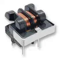
Choke, Common Mode, 2.8 mH, 500 mA, BU9H Series
- Manufacturer: COILCRAFT
- Product type: Radial Leaded Common Mode Chokes / Filters
- Inductance:2.8mH; Rated Current:500mA; Product Range:BU9H Series; SVHC:No SVHC (15-Jan-2019)
- SVHC: No SVHC (25-Jun-2025)
- Inductance: 2.8mH
- Product Range: BU9H Series
- DC Current Rating: 500mA
- DC Resistance Max: 1ohm
- Operating Temperature Max: 125°C
- Operating Temperature Min: -40°C
| Delivery and price | |
|---|---|
| Units per pack | 100 |
| Price | 1.19 € |
| Current stock | 10+ |
| Lead time | 30 days |
Document 260-1

## **– Common Mode Chokes BU Series**

These low cost, high performance choke coils are designed to virtually eliminate line conducted common mode noise.

The BU9S and BU9HS families are ideal for signal line applications; the others can be used in switching power supplies and power supply circuits. All provide significant attenuation of common mode noise across a broad range of frequencies.

For height-restricted applications, the BU9 and BU9S filters are available in a horizontal configuration, which reduces their height to under half an inch (12.5 mm).

For free evaluation samples, contact Coilcraft or request them on-line at **www.coilcraft.com.**

## **Core material** Ferrite

**Terminations** RoHS compliant tin-silver over copper. Other terminations available at additional cost. **Weight** BU9: 3.1 – 4.1 g

BU9H: 3.1 – 4.1 g BU9HS: 3.1 – 3.8 g BU9S: 3.1 – 3.8 g BU10: 6.3 – 6.9 g BU15: 14.6 – 16.1 g BU16: 15.1 – 18.0 g

## **Ambient temperature** –40°C to +125°C

**Storage temperature** Component: –40°C to +125°C. Tray packaging: –40°C to +80°C

**Moisture Sensitivity Level (MSL)** 1 (unlimited floor life at <30°C / 85% relative humidity)

**Failures in Time (FIT) / Mean Time Between Failures (MTBF)**

38 per billion hours / 26,315,789 hours, calculated per Telcordia SR-332 **Packaging** BU9: 100 per tray

BU9H: 100 per tray BU9HS: 100 per tray BU9S: 100 per tray BU10: 100 per tray BU15: 80 per tray BU16: 80 per tray

**PCB washing** Tested with pure water or alcohol only. For other solvents, see Doc787_PCB_Washing.pdf.

Document 260-1 Revised 08/06/13

© Coilcraft Inc. 2013 This product may not be used in medical or high risk applications without prior Coilcraft approval. Specification subject to change without notice. Please check web site for latest information.

**US** +1-847-639-6400   sales@coilcraft.com **UK** +44-1236-730595   sales@coilcraft-europe.com **Taiwan** +886-2-2264 3646   sales@coilcraft.com.tw **China** +86-21-6218 8074   sales@coilcraft.com.cn **Singapore** + 65-6484 8412   sales@coilcraft.com.sg

Document 260-2

## **Common Mode Chokes - BU9, BU9H Series**

|||**Frequency range**|||**Inductance**2|**Inductance difference**|
|---|---|---|---|---|---|---|
||**Impedance max**|**@ 75% of**|**DCR**1|**Current**|**L1, L2**|**L1 - L2**|
|**Part number**|**(kOhms)**|**impedance max**|**(Ohms)**|**max(Aac)**|**min(mH)**|**max(µH)**|
|BU9-103R25BL|60 @ 220 kHz|200 – 240 kHz|3.5|0.25|10.0|200|
|BU9-2820R5BL|53 @ 410 kHz|310 – 430 kHz|1.0|0.50|2.8|50|
|BU9-1320R7BL|52 @ 660 kHz|600 – 700 kHz|0.5|0.70|1.3|50|
|BU9-6011R0BL|36 @ 1300 kHz|1200 – 1400 kHz|0.2|1.00|0.6|25|
|BU9-2011R6BL|5.4 @ 1500 kHz|900 – 2100 kHz|0.1|1.60|0.2|25|
|BU9H-103R25BL|60 @ 220 kHz|200 – 240 kHz|3.5|0.25|10.0|200|
|BU9H-2820R5BL|53 @ 410 kHz|310 – 430 kHz|1.0|0.50|2.8|50|
|BU9H-1320R7BL|52 @ 660 kHz|600 – 700 kHz|0.5|0.70|1.3|50|
|BU9H-6011R0BL|36 @ 1300 kHz|1200 – 1400 kHz|0.2|1.00|0.6|25|
|BU9H-2011R6BL|5.4 @ 1500 kHz|900 – 2100 kHz|0.1|1.60|0.2|25|


1. DCR is per winding

2. Inductance tested at 1 kHz, 1 Vrms, 0 Adc on an Agilent/HP 4284A LCR-meter or equivalent.

3. 1000 Vrms typical isolation between windings.

4. Electrical specifications at 25°C.

## **Typical Attenuation**

## **Typical Impedance**

**==> picture [505 x 177] intentionally omitted <==**

## **BU9**

**==> picture [229 x 213] intentionally omitted <==**

**----- Start of picture text -----**<br>
0.43 Dot 0.69<br>11,0 max indicates 17,5 [max]<br>pin 1<br>0.67<br>0.157 ±0.04 17,0 max<br>4,0 ±1,0<br>2 1 1 4<br>0.024<br>0.31 ±0.02<br>0.276 ±0.02 8,0 ±0,5 0,6<br>7,0 ±0,5 1 4<br>2 3<br>0.276 ±0.02<br>7,0 ±0,5<br>1 4<br>0.31 ±0.02 2 3<br>8,0 ±0,5 0.040<br>1,0<br>Recommended 1 2<br>Board Layout<br>4 3<br>**----- End of picture text -----**<br>


## **BU9H**

**==> picture [229 x 213] intentionally omitted <==**

**----- Start of picture text -----**<br>
0.61 0.69<br>max<br>15,5 17,5 [max]<br>0.157 ±0.04 0.49 max<br>4,0 ±1,0 12,5<br>Dot<br>2 1 indicatespin 1 1 4<br>0.31 ±0.02 0.024<br>0.276 ±0.02 8,0 ±0,5 0,6<br>7,0 ±0,5<br>0.43<br>11,0 max 1 4<br>2 3<br>0.276 ±0.02<br>7,0 ±0,5<br>1 4<br>0.31 ±0.028,0 ±0,5 0.040 2 3<br>1,0<br>Recommended<br>Board Layout 1 2<br>4 3<br>**----- End of picture text -----**<br>


**==> picture [117 x 44] intentionally omitted <==**

**US** +1-847-639-6400   sales@coilcraft.com **UK** +44-1236-730595   sales@coilcraft-europe.com **Taiwan** +886-2-2264 3646   sales@coilcraft.com.tw **China** +86-21-6218 8074   sales@coilcraft.com.cn **Singapore** + 65-6484 8412   sales@coilcraft.com.sg

**==> picture [133 x 45] intentionally omitted <==**

**----- Start of picture text -----**<br>
Document 260-2 Revised 08/06/13<br>© Coilcraft Inc. 2013<br>This product may not be used in medical or high<br>risk applications without prior Coilcraft approval.<br>Specification subject to change without notice.<br>Please check web site for latest information.<br>**----- End of picture text -----**<br>


Document 260-3

## **Common Mode Chokes - BU9S, BU9HS Series**

|||**Frequency range**|||**Inductance**2|**Inductance difference**|
|---|---|---|---|---|---|---|
||**Impedance max**|**@ 75% of**|**DCR**1|**Current**|**L1, L2**|**L1 - L2**|
|**Part number**|**(kOhms)**|**impedance max**|**(Ohms)**|**max(Aac)**|**min(mH)**|**max(µH)**|
|BU9S-153R15BL|71 @ 210 kHz|190 – 230 kHz|5.0|0.15|15.0|300|
|BU9S-7020R3BL|66 @ 330 kHz|300 – 360 kHz|2.5|0.30|7.0|200|
|BU9HS-153R15BL|71 @ 210 kHz|190 – 230 kHz|5.0|0.15|15.0|300|
|BU9HS-7020R3BL|66 @ 330 kHz|300 – 360 kHz|2.5|0.30|7.0|200|


1. DCR is per winding

2. Inductance tested at 1 kHz, 1 Vrms, 0 Adc on an Agilent/HP 4284A LCR-meter or equivalent.

3. 1000 Vrms typical isolation between windings.

4. Electrical specifications at 25°C.

## **Typical Attenuation**

**==> picture [70 x 165] intentionally omitted <==**

## **Typical Impedance**

**==> picture [275 x 176] intentionally omitted <==**

## **BU9S**

## **BU9HS**

**==> picture [494 x 237] intentionally omitted <==**

**----- Start of picture text -----**<br>
0.43 Dot 0.69<br>11,0 max indicatespin 1 17,5 [max] 0.6115,5max 0.6917,5 [max]<br>0.157 ±0.04 017,0.67 max 0.157 ±0.044,0 ±1,0 0.4912,5 max<br>4,0 ±1,0<br>2 1 1 4<br>2 1 1 4 Dot 0.024<br>indicates<br>0.276 ±0.02 pin 1 0.31 ±0.02 0,6<br>0.276 ±0.02 0.024 0.31 ±0.02 7,0 ±0,5 8,0 ±0,5<br>7,0 ±0,5 0,6 8,0 ±0,5 0.43 max<br>11,0<br>1 4 1 4<br>2 3 2 3<br>0.276 ±0.02<br>0.276 ±0.02<br>7,0 ±0,5<br>1 4 1 4 7,0 ±0,5<br>0.31 ±0.028,0 ±0,5 0.0401,0 2 3 0.31 ±0.028,0 ±0,5 0.040 2 3<br>Recommended Recommended 1,0<br>Board Layout 1 4 Board Layout 1 4<br>2 3 2 3<br>**----- End of picture text -----**<br>


**==> picture [117 x 44] intentionally omitted <==**

**US** +1-847-639-6400   sales@coilcraft.com **UK** +44-1236-730595   sales@coilcraft-europe.com **Taiwan** +886-2-2264 3646   sales@coilcraft.com.tw **China** +86-21-6218 8074   sales@coilcraft.com.cn **Singapore** + 65-6484 8412   sales@coilcraft.com.sg

Document 260-3 Revised 08/06/13

© Coilcraft Inc. 2013

This product may not be used in medical or high risk applications without prior Coilcraft approval. Specification subject to change without notice. Please check web site for latest information.

Document 260-4

## **Common Mode Chokes - BU10 Series**

|||**Frequency range**|||**Inductance**2|**Inductance difference**|
|---|---|---|---|---|---|---|
||**Impedance max**|**@ 75% of**|**DCR**1|**Current**|**L1, L2**|**L1 - L2**|
|**Part number**|**(kOhms)**|**impedance max**|**(Ohms)**|**max(Aac)**|**min(mH)**|**max(µH)**|
|BU10-1811R2BL|3.9 @ 1.8 MHz|1000 – 3200 kHz|0.20|1.20|0.18|30|
|BU10-1311R6BL|2.2 @ 2.2 MHz|800 – 2000 kHz|0.12|1.60|0.13|20|
|BU10-1012R2BL|1.6 @ 3.1 MHz|1300 – 8900 kHz|0.08|2.20|0.10|15|
|BU10-6003R0BL|1.0 @ 3.0 MHz|800 – 10000 kHz|0.04|3.00|0.06|10|


1. DCR is per winding

2. Inductance tested at 1 kHz, 1 Vrms, 0 Adc on an Agilent/HP 4284A LCR-meter or equivalent.

3. 1000 Vrms typical isolation between windings.

4. Electrical specifications at 25°C.

## **Typical Attenuation**

## **Typical Impedance**

**==> picture [504 x 177] intentionally omitted <==**

**==> picture [384 x 215] intentionally omitted <==**

**----- Start of picture text -----**<br>
0.67 Dot<br>17,0 max indicates<br>pin 1<br>0.89<br>22,5 max<br>0.177 ±0.04<br>4,5 ±1,0<br>2 1 1 4<br>0.028 0.51 ±0.02<br>0,7 0.394 ±0.02 13,0 ±0,5<br>10,0 ±0,5 0.75<br>19,0 [max] Recommended<br>1 4 Board Layout<br>1 2 2 3<br>0.394 ±0.02<br>10,0 ±0,5<br>4 3 1 4<br>2 3 0.51 ±0.02<br>13,0 ±0,5 0.047<br>1,2<br>**----- End of picture text -----**<br>


**==> picture [117 x 44] intentionally omitted <==**

**US** +1-847-639-6400   sales@coilcraft.com **UK** +44-1236-730595   sales@coilcraft-europe.com **Taiwan** +886-2-2264 3646   sales@coilcraft.com.tw **China** +86-21-6218 8074   sales@coilcraft.com.cn **Singapore** + 65-6484 8412   sales@coilcraft.com.sg

Document 260-4 Revised 08/06/13

© Coilcraft Inc. 2013

This product may not be used in medical or high risk applications without prior Coilcraft approval. Specification subject to change without notice. Please check web site for latest information.

Document 260-5

## **Common Mode Chokes - BU15 Series**

|||**Frequency range**|||**Inductance**2|**Inductance difference**|
|---|---|---|---|---|---|---|
||**Impedance max**|**@ 75% of**|**DCR**1|**Current**|**L1, L2**|**L1 - L2**|
|**Part number**|**(kOhms)**|**impedance max**|**(Ohms)**|**max(Aac)**|**min(mH)**|**max(µH)**|
|BU15-4530R4BL|400 @ 230 kHz|140 – 160 kHz|3.0|0.40|45.0|300|
|BU15-1430R7BL|115 @ 470 kHz|400 – 650 kHz|1.0|0.70|14.0|300|
|BU15-7521R0BL|60 @ 600 kHz|420 – 720 kHz|0.6|1.00|7.5|150|
|BU15-4421R3BL|36 @ 670 kHz|430 – 1000 kHz|0.3|1.30|4.4|100|
|BU15-2721R6BL|20 @ 1000 kHz|510 – 1400 kHz|0.2|1.60|2.7|60|


1. DCR is per winding

2. Inductance tested at 1 kHz, 1 Vrms, 0 Adc on an Agilent/HP 4284A LCR-meter or equivalent.

3. 1000 Vrms typical isolation between windings.

4. Electrical specifications at 25°C.

## **Typical Attenuation**

## **Typical Impedance**

**==> picture [504 x 178] intentionally omitted <==**

**==> picture [372 x 211] intentionally omitted <==**

**----- Start of picture text -----**<br>
0.75 max Dot 0.91<br>19,0 indicates 23,0  [max]<br>pin 1<br>1.08<br>0.177 ±0.04 27,5 max<br>4,5 ±1,0<br>2 1 1 4<br>0.028 0.51 ±0.02<br>0,7 13,0 ±0,5<br>0.40 ±0.02 Recommended<br>10,0 ±0,5<br>Board Layout<br>1 4<br>2 3<br>1 2<br>0.40 ±0.02<br>10,0 ±0,5<br>4 3 1 4<br>2 3<br>0.51 ±0.02<br>13,0 ±0,5 0.047<br>1,2<br>**----- End of picture text -----**<br>


**==> picture [117 x 44] intentionally omitted <==**

**US** +1-847-639-6400   sales@coilcraft.com **UK** +44-1236-730595   sales@coilcraft-europe.com **Taiwan** +886-2-2264 3646   sales@coilcraft.com.tw **China** +86-21-6218 8074   sales@coilcraft.com.cn **Singapore** + 65-6484 8412   sales@coilcraft.com.sg

Document 260-5 Revised 08/06/13

© Coilcraft Inc. 2013

This product may not be used in medical or high risk applications without prior Coilcraft approval. Specification subject to change without notice. Please check web site for latest information.

Document 260-6

## **Common Mode Chokes - BU16 Series**

|||**Frequency range**|||**Inductance**2|**Inductance difference**|
|---|---|---|---|---|---|---|
||**Impedance max**|**@ 75% of**|**DCR**1|**Current**|**L1, L2**|**L1 - L2**|
|**Part number**|**(kOhms)**|**impedance max**|**(Ohms)**|**max(Aac)**|**min(mH)**|**max(µH)**|
|BU16-4530R5BL|285 @ 150 kHz|140 – 160 kHz|2.3|0.50|45.0|900|
|BU16-2530R7BL|120 @ 200 kHz|160 – 220 kHz|1.3|0.70|25.0|500|
|BU16-1031R0BL|60 @ 320 kHz|260 – 390 kHz|0.5|1.00|10.0|200|
|BU16-4021R5BL|20 @ 470 kHz|360 – 600 kHz|0.3|1.50|4.0|80|
|BU16-2022R0BL|11 @ 690 kHz|450 – 900 kHz|0.2|2.00|2.0|50|


1. DCR is per winding

2. Inductance tested at 1 kHz, 1 Vrms, 0 Adc on an Agilent/HP 4284A LCR-meter or equivalent.

3. 1000 Vrms typical isolation between windings.

4. Electrical specifications at 25°C.

## **Typical Attenuation**

## **Typical Impedance**

**==> picture [504 x 177] intentionally omitted <==**

**==> picture [389 x 220] intentionally omitted <==**

**----- Start of picture text -----**<br>
0.75 0.91<br>max Dot<br>19,0 indicates 23,0 [max]<br>pin 1<br>1.08<br>max<br>0.177 ±0.04 27,5<br>4,5 ±1,0<br>2 1 1<br>0.028<br>0.51 ±0.02<br>0,7<br>0.394 ±0.02 13,0 ± 0,5<br>10,0 ±0,5<br>Recommended<br>Board Layout<br>1 4<br>1 2 2 3<br>0.394 ±0.02<br>10,0 ±0,5<br>4 3 1 4<br>2 3<br>0.51 ±0.02<br>13,0 ±0,5 0.047<br>1,2<br>**----- End of picture text -----**<br>


**==> picture [117 x 44] intentionally omitted <==**

**US** +1-847-639-6400   sales@coilcraft.com **UK** +44-1236-730595   sales@coilcraft-europe.com **Taiwan** +886-2-2264 3646   sales@coilcraft.com.tw **China** +86-21-6218 8074   sales@coilcraft.com.cn **Singapore** + 65-6484 8412   sales@coilcraft.com.sg

Document 260-6 Revised 08/06/13

© Coilcraft Inc. 2013 This product may not be used in medical or high risk applications without prior Coilcraft approval. Specification subject to change without notice. Please check web site for latest information.
Updated at April 29, 2026
Coilcraft is a globally recognized leader in the design and manufacture of high-performance magnetic components. Renowned for its engineering excellence, reliable delivery, and stringent quality standards, the company provides essential solutions for a wide array of demanding applications, including signal processing, RF, power management, and timing circuits. Our comprehensive portfolio of Coilcraft components is centered on their industry-leading inductor technologies. This encompasses a vast selection of high-efficiency power inductors designed to optimize modern power supply architectures, alongside precision RF inductors engineered to deliver exceptional stability and performance in high-frequency communications and wireless applications. To support complete electromagnetic compatibility and comprehensive circuit design, we also offer a variety of Coilcraft's specialized magnetic solutions. This includes robust common mode chokes and filters for effective EMC and RFI suppression, current sensing transformers, and a selection of inductor kits and assortments that provide design engineers with versatile options for rapid prototyping and development.
About Novapart
Novapart is a B2B electronic component broker specialising in stock shortages and cost reduction. We source hard-to-find parts and identify compliant alternatives across a catalogue of 410,000+ components from 500+ manufacturers.
Learn more →Stock Shortage Specialist
When a component is unavailable, discontinued or has an unacceptable lead time, we tap into our network of vetted European and Asian distributors to source what you need — without compromising on quality or traceability.
Request a quote →Compliant Alternatives
We identify pin-to-pin, electrically equivalent substitutes that meet the same certifications (RoHS, AEC-Q100, REACH) as your original specification — validated against datasheets, not just part numbers. Often at a lower cost.
BOM Analysis service →