
Image not available
Illustrative purposes only

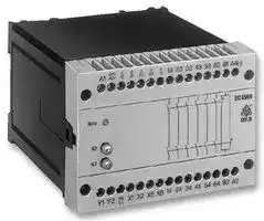
BO 5988.61/024 DC 24V + AC 230V
Safety Relay, 24 VDC, 6PST-NO, BO 5988 Series, DIN Rail, 5 A, Screw
⚠️ Reference pricing provided. In case of supply shortages, we will connect you with our trusted procurement partners to ensure your project's continuity.
- Manufacturer: DOLD
- Product type: Safety Relays
- Coil Voltage:24VDC; Contact Configuration:6PST-NO; Product Range:BO 5988 Series; Relay Mounting:DIN Rail; Contact Current:5A; Relay Terminals:Screw; Contact Voltage AC Nom:230V; Contac
- IP Rating: IP20, IP40
- Coil Voltage: 24VDC
- Product Range: BO 5988 Series
- Relay Mounting: DIN Rail
- Contact Current: 5A
- Relay Terminals: Screw
- Contact Material: -
- Contact Configuration: 6PST-NO
- Contact Voltage AC Nom: 230V
- Contact Voltage DC Nom: -
| Delivery and price | |
|---|---|
| Units per pack | 1 |
| Price | 509.05 € |
| Current stock | 10+ |
| Lead time | 30 days |
Datasheet

**Safety technique**

## **Emergency stop module BO 5988 SAFEMASTER[®]**

- According to

- SIL-Claimed Level (SIL CL) 3 to EN 62061

- Performance Level (PL) e to DIN EN ISO 13849-1

**==> picture [5 x 22] intentionally omitted <==**

**----- Start of picture text -----**<br>
0221562<br>**----- End of picture text -----**<br>


- Category 4 to EN 954-1

- Output: max. 6 NO, 1 NC contacts or 1 NO contact for AC 250 V

- Optionally with release delayed NO contact to 10 min

- 1-channel or 2-channel connection

- Line fault detection at On pushbutton

- Optionally automatic On function after connection of operating voltage or activation via On pushbutton

- Optionally cross fault detection in emergency stop control circuit

- Optionally dual voltage version

- Feedback circuit X1-X2 for monitoring external contactors

- Integrated short-circuit and overvoltage protection

- Optionally with protective seperation to IEC/EN 60 140, IEC/EN 60 947-1

**Function diagram**

- LED displays for channels 1 and 2 and supply

- Removable terminal strips

- Wire connection: also 2 x 1,5 mm[2] stranded ferruled (isolated), DIN 46 228-1/-2/-3-4 or

**==> picture [529 x 538] intentionally omitted <==**

**----- Start of picture text -----**<br>
<br>Pushbutton<br>on DIN 46 228-1/-2/-3-4 or<br>2 x 2,5 mm [2]  stranded ferruled DIN 46 228-1/-2/-3<br>Mains or • Width 100 mm<br>emergency-<br>stop (Off)<br>* Approvals and marking<br>K1<br>* * 1)<br>K2 * Short-circuit detection<br>== at On pushbutton ET Canada Canada / USA<br>M 6800 BG valid 31.12.2009;    [1)]  pending;     * see variants<br>Applications<br>Block diagram<br>Protection of people and machines<br>A1 A2 A4 S11/A3(+) X1 X2 Y1 Y2 S12 S12 S22 13 23 33 43 53 63 81 • Emergency stop circuits on machines<br>• Monitoring of safety gates<br>Indication<br>Overvoltage and short K2 K3 Monitoring LED power supply: on, when operating voltage present<br>circuit protection & logic K2 LED K2:LED K3: on, when supply on relay K2on, when supply on relay K3<br>K23<br>only at BO 5988/4_ _,<br>24V ... K23 K2 K3 K3 BO 5988/5_ _:<br>LED KT2, KT3: on, when delayed contacts are energised<br>Mains<br>K2 K3 Note<br>Safety category 4 according to EN 954-1 only at applications with<br>E ti il cross fault detection.<br>PE(-) S21 S23 14 24 34 44 54 64 82 At delayed contacts: Safety category 3 according to EN 954-1 for<br>M6801_b delays up to 30 s max. For longer delays category 1.<br>Circuit diagrams<br>S11 S11 S11<br>A1 A3 S12 S21 S23 S22 S12 13 23 33 43 53 63 81 A4 A1 A3 S12 S21 S23 S22 S12 13 23 33 77 81 A4 A1 A3 S12 S21 S23 S22 S12 13 23 33 81 A4<br>(+) (+) (+)<br>A1 PE(-) 13 23 33 43 53 63 81 A1 PE(-) 13 23 33 77 81 A1 PE(-) 13 23 33 81<br>S12<br>S12 S12<br>S12<br>S12 S12<br>S21 S21 S21<br>S22 K2 S22 S22<br>S23<br>S23 K2 S23 K2<br>X1 K23 X1 X1<br>X2 X2 X2<br>X5 X5 K3 X5 K3<br>X6 K3 X6 X6<br>Y1Y2 Y2Y1 tv Y2Y1<br>A2 S11/A3+ 14 24 34 44 54 64 82 A2 S11/A3+ 14 24 34 78 82 A2 S11/A3+ 14 24 34 82<br>Y1 Y2 PE X1 X2 X5 X6 14 24 34 44 54 64 82 A2 Y1 Y2 PE X1 X2 X5 X6 14 24 34 78 82 A2 Y1 Y2 PE X1 X2 X5 X6 14 24 34 82 A2<br>(-) (-) (-)<br>M 7172 M 7173 M 7174<br>BO 5988.61 BO 5988.47 BO 5988.48<br>**----- End of picture text -----**<br>


All technical data in this list relate to the state at the moment of edition. We reserve the right

BO 5988 / 02.06.09 e

1

## **Notes**

Jumper assignment for functions:

## **Technical Data**

## **Output**

Activation via On pushbutton / or automatic On function

## **Contact**

|Jumper assignment for functions:<br>Activation via On pushbutton / or automatic On function<br>**Notes**|Jumper assignment for functions:<br>Activation via On pushbutton / or automatic On function<br>**Notes**|Jumper assignment for functions:<br>Activation via On pushbutton / or automatic On function<br>**Notes**|Jumper assignment for functions:<br>Activation via On pushbutton / or automatic On function<br>**Notes**|
|---|---|---|---|
|On push-<br>button<br>Y1 - Y2|Jumper<br>X5 - X6||Function|
||||The output contacts are switches only<br>after operation of the On pushbutton.<br>Line fault monitoring at the On pushbutton|
|M8687|||Automatic On function for operating<br>voltage Off/On or after emergency<br>stop release|


Line fault detection at the On pushbutton:

The output contacts cannot be closed if the On pushbutton is already closed before the voltage is applied to S12, S22 (also in the event of a line fault at the On pushbutton).

A line fault at the On pushbutton which occures after activation of the device is recognized when swichting-on takes place again and closing of the output contacts is then prevented.

If a line fault occurs at the On pushbutton  after the voltage is already present at S12, S22, undesired activation will take place, because this line fault does not differ from the normal closing function.

The gold-plated contacts of the BO 5988 also mean that this module is suitable for switching small loads of 1 mVA ... 7 VA, 1 mW ... 7 W in the range 0,1 ... 60 V, 1 ... 300 mA. The contacts also permit the maximum switching current. However, since the gold plating is burnt off at this current level, the device is no longer suitable for switching small loads after this.

The PE terminal permits operation of the device in IT systems with insulation monitoring and also serves as a reference point for testing the control voltage. The internal short-circuit protection will be bridged on DC devices, if the protective ground is connected to terminal PE. One or more extension modules BN 3081 or external contactors with positively-driven contacts may be used to multiply the number of contacts of the emergency stop module BO 5988.

## **ATTENTION - AUTOMATIC START!**

According to IEC/EN 60 204-1 part 9.2.5.4.2 it is not allowed to restart automatically after emergency stop. Therefore the machine control has to disable the automatic start after emergency stop.

## **Technical data**

BO 5988.48: BO 5988.61: BO 5988.62: BO 5988.47:

3 NO, 1 NC indicator contact

6 NO, 1 NC indicator contact

6 NO, 1 NO indictor contact 3 NO, 1 NC indicator contact

1 NO release delayed

The NO contacts 13...63 / 14...64 are safety contacts. The NO contact 77/78 can be use as safety contact for units with time delay up to max. 30 s.

**ATTENTION! The NC contacts 81-82 or one NO contact 83-84 can only be used for monitoring.**

## **Operate time**

manual restart: typ. 30 ms automatic restart: 1 s

## **Release time**

opening in secondary circuit (S12-S22): 30 ms ± 50 % opening in supply circuit BO5988.47, BO 5988.48: 100 ms + 50 % BO 5988.61, BO 5988.62: 50 ms + 50 % **Time delay tv** :

100 ms + 50 % 50 ms + 50 % Auxiliary supply is not necessary during elapse of time:

BO 5988.47/1 _ _ : BO 5988.47/2 _ _ :

|0,1 ... 1 s<br>0,3|...|3 s|
|---|---|---|
|0,5 ... 5 s<br>1|...|10 s|
|1 s, 3 s, 5 s, 10 s|||
|Auxiliary supply must||be connected|
|during elapse of time:|||
|0,1...<br>1 s<br>0,1|...|1 min|
|0,3...<br>3 s<br>0,3|...|3 min|
|1<br>... 10 s<br>0,5|...|5 min|
|3<br>... 30 s<br>1|...|10 min|
|1 s, 3 s, 10, 30 s|||


BO 5988.47/4 _ _:

BO 5988.47/5 _ _ :

1 min, 3 min, 5 min, 10 min

## **Repeat accuracy**

BO 5988.47/1 _ _ and BO 5988.47/2 _ _ : + 15 % of setting value BO 5988.47/4 _ _ and BO 5988.47/5 _ _ : + 1 % of setting value **Contact type:** Relay, positively-driven **Nominal output voltage:** AC 250 V DC: see limit curve for arc-free operation

## Signalling contact of

## **Input**

**Nominal voltage UN** BO 5988.--/-00: DC 24 V BO 5988.--/-24: DC 24 V[1)] + AC 24 V[2)] DC 24 V[1)] + AC 48 V[2)] DC 24 V[1)] + AC 110 V[2)] DC 24 V[1)] + AC 230 V[2)] DC 24 V[1)] + AC 240 V[2)] 1) at terminals A3-A4

2) at terminals A1-A2 **Voltage range:** AC 0,8 ... 1,1 UN at 10 % residual ripple: DC 0,9 ... 1,2 UN at 48 % residual ripple: DC 0,8 ... 1,1 UN **Nominal consumption:** AC: approx. 6 VA, DC: approx. 3 W **Nominal frequency:** 50 / 60 Hz **Control voltage** at S11: typ. DC + 24 V at S21: 0 V **Control current:** typ. DC 110 mA **Minimum voltage** at terminals S12, S22: DC 21 V with activated device **Recovery time:** 2 s

A minimum switch-off time of 20 s must be observed if the line fault monitoring function at the On pushbutton is active

BO 5988.61 and BO 5988.62: AC 10 ... 250 V, DC 10 ... 120 V for AC/DC 0,1 ... 1 A

see total current limit curve (max. 10 A in one contact path)

**Thermal current Ith:**

release delayed NO contact 77-78 at BO 5988.47: max. 8 A

|release delayed NO contact<br>77-78 at BO 5988.47:|max. 8 A||
|---|---|---|
|**Switching capacity**|||
|to AC 15|||
|NO contact:|5 A / AC 230 V|IEC/EN 60 947-5-1|
|NC contact:|2 A / AC 230 V|IEC/EN 60 947-5-1|
|BO 5988.47|||
|release delayed NO contact:<br>to DC 13<br>NO contact:<br>NC contact:<br>to DC 13<br>NC contact:<br>**Electrical life**|3 A / AC 230V<br>IEC/EN 60 947-5-1<br>4 A / DC 24 V<br>IEC/EN 60 947-5-1<br>4 A / DC 24 V<br>IEC/EN 60 947-5-1<br>10 A / 24 V   > 105<br>On: 0,4 s, Off: 9,6 s||
|to AC 15 at 2 A, AC 230 V:|105switching cycles IEC/EN 60 947-5-1||
|to DC 13 at 2 A, AC 230 V:|> 240 x 103switching||
||cycles|IEC/EN 60 947-5-1|
|**Permissible operating**|||
|**frequency:**|600 switching cycles / h||
|**Short circuit strength**|||
|max. fuse rating:|6 A gL|IEC/EN 60 947-5-1|
|max. line circuit breaker:|C 10 A||
|**Mechanical life:**|30 x 106switching cycles||


BO 5988 / 02.06.09 e

2

## **Technical Data**

## **General Data**

**Operating mode:** Continuous operation **Temperature range:** - 15 ... + 50°C **Clearance and creepage distances** rated impuls voltage / pollution degree: 4 kV / 2 IEC 60 664-1 **EMC** Electrostatic discharge: 8 kV (air) IEC/EN 61 000-4-2 HF irradiation: 10 V / m IEC/EN 61 000-4-3 Fast transients: 2 kV IEC/EN 61 000-4-4 Surge voltages between wires for power supply: 0,5 kV IEC/EN 61 000-4-5 between wire and ground: 2 kV IEC/EN 61 000-4-5 HF-wire guided: 10 V IEC/EN 61 000-4-6 Interference suppression: Limit value class B EN 55 011 **Degree of protection** Housing: IP 40 IEC/EN 60 529 Terminals: IP 20 IEC/EN 60 529 **Housing:** Thermoplastic with V0 behaviour according to UL subject 94 **Vibration resistance:** Amplitude 0,35 mm IEC/EN 60 068-2-6 frequency 10 ... 55 Hz **Climate resistance:** 15 / 050 / 04 IEC/EN 60 068-1 **Terminal designation:** EN 50 005 **Wire connection:** 1 x 4 mm[2] solid or

1 x 2,5 mm[2] stranded ferruled (isolated) or 2 x 1,5 mm[2] stranded ferruled (isolated) DIN 46 228-1/-2/-3/-4 or 2 x 2,5 mm[2] stranded ferruled DIN 46 228-1/-2/-3 **Wire fixing:** Plus-minus terminal screws M 3,5 box terminal with wire protection **Mounting:** DIN rail IEC/EN 60 715 **Weight:** 850 g

## **Dimensions**

**Width x height x depth:** 100 x 74 x 121 mm

## **Safety related data**

## **Probability of dangerous**

**Failure per Hour (PFHD):** 4,77[.] 10[-10] 1/h (BO 5988.61, BO 5988.62) 8,60[.] 10[-10] 1/h (BO 5988.47/124) **Safe Failure Fraction (SFF):** 99,4 % (BO 5988.61, BO 5988.62) 99,3 % (BO 5988.47/124)

**Proof Test Intervall (T1):** 20 Years

The values stated above are valid for the standard type. Safety data for other variants are available on request nfo

## **Standard types**

BO 5988.61/024   DC 24 V + AC 230 V   50 / 60 Hz Article number: 0040375

stock item

- Dual voltage version

- Output: 6 NO contacts, 1 NC contact as monitoring contact

- Width: 100 mm

BO 5988.47/124   DC 24 V + AC 230 V   50 / 60 Hz   1 ...10 s Article number: 0040430 stock item

- Dual voltage version

- Output: 3 NO contacts, 1 NC contact as monitoring contact, 1 release delayed NO contact

- With adjustable time delay tv to 10 s

- Width: 100 mm

## **Variants**

BO 5988._ _ /60: with CSA approval BO 5988._ _ /61: with UL approval (Canada/USA) Auxiliary supply is not nesseary during elapse of time: BO 5988.47 / 1 _ _: 3 NO / 1 NC contacts + tv adjustable BO 5988.47 / 2 _ _: 3 NO / 1 NC contacts + tv fixed Auxiliary supply must be connected during elapse of time: BO 5988.47 / 4 _ _: 3 NO / 1 NC contacts + tv adjustable BO 5988.47 / 5 _ _: 3 NO / 1 NC contacts + tv fixed Without time delay tv: BO 5988.48 / 0_ _ : 3 NO / 1 NC contacts BO 5988.61 / 0_ _ : 6 NO / 1 NC contacts as monitoring contact BO 5988.62 / 0_ _ : 6 NO / 1 NC contacts as monitoring contact BO 5988. _ _ / _00: single voltage model BO 5988. _ _ / _24: dual voltage model BO 5988.61 / 106:

Protective seperation of control and load circuits according to IEC/EN 61 140, IEC/EN 60 947 4 kV / 2 referred to overvoltage category II with basic insulation to IEC 60 664 of 2,5 kV / 2. BO 5988.61 / 324: Dual voltage model 0,5 s operate delay with automatic restart

## **Ordering example for variants**

BO 5988.47/124 1 ... 10 s DC 24 V + AC 230 V 50 / 60 Hz

Nominal frequency Nominal voltage Time delay 00: 1 nominal voltage 24: 2 nominal votlages 0: without tv without auxiliary supply during time elapse: 1: tv adjustable 2: tv fixed with auxiliary supply during time elapse: 4: tv adjustable 5: tv fixed Contacts Type

BO 5988 / 02.06.09 e

3

## **Characteristics**

**==> picture [118 x 142] intentionally omitted <==**

**----- Start of picture text -----**<br>
250<br>200<br>150<br>100<br>50<br>0<br>1 2 3 4 5 6 7 8 9 10<br>Switching current I [A]<br>M 6732<br>[V]<br>U<br>Switching voltage<br>**----- End of picture text -----**<br>


Limit curve for arc-free operation with resistive load

**==> picture [195 x 129] intentionally omitted <==**

**----- Start of picture text -----**<br>
2 2<br>I [ A ]<br>250<br>max. 225<br>200 limit curve<br>150<br>1<br>100<br>50<br>2<br>10 20 30 40 50 T [ C]<br>M6802_a<br>**----- End of picture text -----**<br>


## **Total current limit curve**

It is necessary to use the square of the currents in order to obtain a linear limit curve.

## **General formula for determination of the maximum ambient temperature**

- A) Sum of currents[2] per safety contact = value on scale Σ I[2 ] (A[2] ) B) Max. ambient temperature T = Cross point of scale Σ I[2 ] (A[2] ) with limit curve

## **Example 1**

A) (4A)[2] + (4A)[2] + (4A)[2] + (4A)[2] + (4A)[2] + (4A)[2] = 96 A[2] (Scale Σ I[2] ) B) Max. ambient temperature T = 43°C (point 1)

## **Example 2**

- A) (0,5 A)[2] + (1 A)[2] + (2 A)[2] + (1 A)[2] = 6,25 A[ 2] (Scale Σ I[2] ) B) Max. ambient temperature T = 49°C (point 2)

## **Please note:**

The total current[2] can still be 1,5 A[2] at 50°C , i.e. 0,5 A per safety contact A) (0,5 A)[2] + (0,5 A)[2] + (0,5 A)[2] + (0,5 A)[2] + (0,5 A)[2] +( 0,5 A)[2] = 1,5 A[2] B) Max. ambient temperature = 50°C

## **Application examples**

**==> picture [259 x 171] intentionally omitted <==**

**----- Start of picture text -----**<br>
L1<br>Off<br>Emergency-<br>On stop Positively-driven safetycontacts Auxiliarycontact<br>A1 S11/A3 Y1 Y2 S12 S12 S22 S21 S23 13 23 33 43 53 63 81<br>BO 5988.61<br>A2 A4 X1 X2 PE(-) X5 X6 14 24 34 44 54 64 82<br>N<br>M6803_a<br>E- - -<br>E - - E- - - - - - - -<br>**----- End of picture text -----**<br>


Two-channel emergency stop circuit without cross fault detection. Activation via On pushbutton. - - - Jumper X5 - X6: A jumper must be fitted X5 - X6 for the automatic On function. The On pushbutton is not required.

## **Application examples**

**==> picture [259 x 172] intentionally omitted <==**

**----- Start of picture text -----**<br>
L1<br>Emergency-<br>stop E- - - - - - - - - - - - - -<br>On Positively-driven safetycontacts Auxiliarycontact<br>A1 S11/A3 Y1 Y2 S12 S12 S22 S21 S23 13 23 33 43 53 63 81<br>BO 5988.61<br>A2 A4 X1 X2 PE(-) X5 X6 14 24 34 44 54 64 82<br>N<br>M6804_a<br>E - -<br>**----- End of picture text -----**<br>


Two-channel emergency-stop circuit with cross fault detection. Activation via On pushbutton. - - - Jumper X5 - X6: A jumper must be fitted X5 - X6 for the automatic On function. The On pushbutton is not required.

**==> picture [259 x 172] intentionally omitted <==**

**----- Start of picture text -----**<br>
L1<br>Off<br>On Positively-driven safetycontacts Auxiliarycontact<br>Emergency-<br>stop<br>A1 S11/A3 Y1 Y2 S12 S12 S22 S21 S23 13 23 33 43 53 63 81<br>BO 5988.61<br>A2 A4 X1 X2 PE(-) X5 X6 14 24 34 44 54 64 82<br>N<br>M6805_a<br>E- - -<br>E- - - - -<br>E - -<br>**----- End of picture text -----**<br>


One-channel emergency stop circuit. This circuit does not have any redundancy in the emergency stop control device circuit.

BO 5988 / 02.06.09 e

4

## **Application examples**

**==> picture [259 x 172] intentionally omitted <==**

**----- Start of picture text -----**<br>
L1<br>N<br>Off<br>Emergency-<br>stop<br>On Positively-driven safetycontacts Auxiliarycontact<br>A1 S11/A3 Y1 Y2 S12 S12 S22 S21 S23 13 23 33 43 53 63 81<br>BO 5988.61<br>A2 A4 X1 X2 PE(-) X5 X6 14 24 34 44 54 64 82<br>M6806_a<br>E- - -<br>E- - - - - - - -<br>E - -<br>**----- End of picture text -----**<br>


Two-pole emergency stop circuit with emergency stop control device in the supply circuit.

Application for long emergency stop loops where the control voltage drops below the minimum voltage of 21 V.

## **Attention:**

## **Application examples**

**==> picture [259 x 172] intentionally omitted <==**

**----- Start of picture text -----**<br>
L1<br>Off<br>Emergency-<br>On stop<br>A1 S11/A3 Y1 Y2 S12 S12 S22 S21 S23 13 23 33 43 53 63 81<br>BO 5988.61<br>A2 A4 X1 X2 PE(-) X5 X6 14 24 34 44 54 64 82<br>K4<br>K4 K5<br>K5<br>N<br>M6807_a<br>E- - -<br>E - - E- - - - - - - -<br>**----- End of picture text -----**<br>


Contact reinforcement by external contactors, two-channel. The output contacts can be reinforced by external contactors with positively-driven contacts for switching currents > 8 A. Functioning of the external contactors is monitored by looping the NC contacts into the closing circuit (terminals X1 - X2).

Single faults (e.g. line faults at the emergency stop control device) are not detected with this external circuit configuration.

**==> picture [259 x 172] intentionally omitted <==**

**----- Start of picture text -----**<br>
L1<br>S1 Positively-driven safety Auxiliary<br>S2 contacts contact<br>A1 S11/A3 Y1 Y2 S12 S12 S22 S21 S23 13 23 33 43 53 63 81<br>BO 5988.61<br>A2 A4 X1 X2 PE(-) X5 X6 14 24 34 44 54 64 82<br>N<br>M6809_a<br>**----- End of picture text -----**<br>


Two-channel monitoring of a safety gate. S1 must not close before S2

**==> picture [259 x 171] intentionally omitted <==**

**----- Start of picture text -----**<br>
L1<br>Off<br>Emergency-<br>On stop<br>A1 S11/A3 Y1 Y2 S12 S12 S22 S21 S23 13 23 33 43 53 63 81<br>BO 5988.61<br>A2 A4 X1 X2 PE(-) X5 X6 14 24 34 44 54 64 82<br>K4<br>K4 K5<br>K5<br>N<br>M6808_a<br>E- - -<br>E - - E- - - - - - - -<br>**----- End of picture text -----**<br>


Contact reinformcement by external contactors with reduced safety level.

BO 5988 / 02.06.09 e

5

**E. DOLD & SÖHNE KG • D-78114 Furtwangen** • PO Box 1251 • Telephone (+49) 77 23 / 654-0 • Telefax (+49) 77 23 / 654-356

e-mail: dold-relays@dold.com • internet: http://www.dold.com

BO 5988 / 02.06.09 e

6
Updated at April 23, 2026
About Novapart
Novapart is a B2B electronic component broker specialising in stock shortages and cost reduction. We source hard-to-find parts and identify compliant alternatives across a catalogue of 410,000+ components from 500+ manufacturers.
Learn more →Stock Shortage Specialist
When a component is unavailable, discontinued or has an unacceptable lead time, we tap into our network of vetted European and Asian distributors to source what you need — without compromising on quality or traceability.
Request a quote →Compliant Alternatives
We identify pin-to-pin, electrically equivalent substitutes that meet the same certifications (RoHS, AEC-Q100, REACH) as your original specification — validated against datasheets, not just part numbers. Often at a lower cost.
BOM Analysis service →