
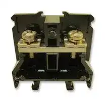


BN30W
TERMINAL BLOCK, DIN RAIL, 1 POSITION, 18-10AWG
- Manufacturer: IDEC
- Product type: DIN Rail Terminal Blocks
- No. of Positions:2Positions; Wire Size AWG Min:18AWG; Wire Size AWG Max:10AWG; Conductor Area CSA:5.5mm²; Wire Connection Method:Screw; Rated Current:30 90B5265
- SVHC: No SVHC (16-Jul-2019)
- No. of Levels: 1
- Product Range: -
- Rated Current: 30A
- Rated Voltage: 600V
- No. of Positions: 2Ways
- Wire Size AWG Max: 10AWG
- Wire Size AWG Min: 18AWG
- Conductor Area CSA: 5.5mm²
- Wire Connection Method: Screw
| Delivery and price | |
|---|---|
| Units per pack | 1000 |
| Price | 1.54 € |
| Current stock | 10+ |
| Lead time | 30 days |
**BNH/BN Terminal Blocks**

**Terminal Blocks**

## **BNH/BN Series**

## **Key features of the BNH/BN series include:**

- Touch-down terminals with spring-loaded captive screws

-

- Jumpers available up to 30A model

- Fuse block with or without blown-fuse indicator in neon or LED

- Mount on 35mm standard DIN rail

File No.  R9551701 UL Recognized CSA Certifi ed File No. E78117 File No. LR64803 J9551516 (power blocks) R9650688 (dual-deck blocks)

## **Specifi cations**

|**Part Numbers**|**BNH10W**|**BNH15MW**|**BNH15LW**|**BNH30W**|
|---|---|---|---|---|
|**Voltage/Current**<br>Size<br>Type<br>(N-m)<br>(in-lbs.)<br>PVC<br>Fiberglass<br>End clip<br>**Ring Terminal Jumpers**<br>**Fork Terminal Jumpers**|0.275” (7mm)<br>UL, CSA, TUV<br>1<br>22 to 16 AWG<br>600V / 10A<br>M3<br>Touch-down<br>35mm DIN rail<br>0.6 - 1.0<br>5.3 - 8.9<br>BNE15W<br>BNL-5<br>BNC230<br>BNM7<br>BNM9<br>BNM3<br>BNJ16<br>BNJ16F|0.315” (8mm)<br>UL, CSA, TUV<br>1<br>22 to 14 AWG<br>600V / 10A<br>M3<br>Touch-down<br>35mm DIN rail<br>0.6 - 1.0<br>5.3 - 8.9<br>BNE15W<br>BNL-5<br>BNC230<br>BNM7<br>BNM9<br>BNM3<br>BNJ26W<br>BNJ26FW|0.413” (10.5mm)<br>UL, CSA, TUV<br>1<br>22 to 14 AWG<br>600V / 15A<br>M3.5<br>Touch-down<br>35mm DIN rail<br>1.0 - 1.3<br>8.9 - 11.5<br>BNE15W<br>BNL-5<br>BNC230<br>BNM7<br>BNM9<br>BNM3<br>BNJ46<br>BNJ46F|0.472” (12mm)<br>UL, CSA, TUV<br>1<br>18 to 10 AWG<br>600V / 30A<br>M4<br>Touch-down<br>35mm DIN rail<br>1.4 - 2.0<br>12.4 - 17.8<br>BNE30W<br>BNL-5<br>BNC230<br>BNM7<br>BNM9<br>BNM3<br>BNJ56<br>BNJ56F|


1. BNDN1000 aluminum DIN rails are available in 1 meter lengths.

2. Marking strips are available in 1 meter lengths.

3. Jumpers are available in groups of six.

4. Remove the “H” in the terminal block part number for standard screw type (ex. BNH10W becomes BN10W).

USA: 800-262-IDEC          Canada: 888-317-IDEC

861

**BNH/BN Terminal Blocks**

**Terminal Blocks**

## **Specifi cations, continued**

##

|**Part Numbers**<br>**Appearance**|**BNH50W**<br>7<br>=<br>cL|**BN75W**<br>:|**BN150W**<br>- i<br>t—|**BNDH15W**<br>a<br>eas|
|---|---|---|---|---|
|**Width**<br>**Approvals**<br>**No. of Poles**<br>**Wire Sizes**<br>**Voltage/Current**<br>**Terminals**<br>Size<br>Type|0.610” (15.5mm)<br>UL, CSA, TUV<br>1<br>16 to 6 AWG<br>600V / 50A<br>M5<br>Touch-down|0.787” (20mm)<br>UL, CSA, TUV<br>1<br>16 to 4 AWG<br>600V / 75A<br>M6<br>Hex bolt|1.024” (26mm)<br>UL, CSA, TUV<br>1<br>16 to 0 AWG<br>600V / 150A<br>M8<br>Hex bolt|0.315” (8mm)<br>UL, CSA, TUV<br>2<br>22 to 14 AWG<br>600V / 10A<br>M3<br>Touch-down|
|**Mounting**|35mm DIN rail|35mm DIN rail|35mm DIN rail|35mm DIN rail, surface|
|**Terminal**<br>**Torque**<br>(N-m)<br>(in-lbs.)<br>**End Plate**<br>**DIN Rail Stop**<br>**Dust Cover**<br>**Marking**<br>**Strip**<br>PVC<br>Fiberglass<br>End clip|2.6 - 3.7<br>23.1 - 32.8<br>BNE50W<br>BNL-5<br>BNC320<br>BNM7<br>BNM9<br>BNM3|3.9 - 5.4<br>34.6 - 47.9<br>BNE75W<br>BNL-6<br>BNC420<br>BNM7<br>BNM9<br>BNM3|10 - 13.5<br>88.8 - 119.8<br>BNE150W<br>BNL-6<br>BNC520<br>BNM7<br>BNM9<br>BNM3|0.6 - 1.0<br>5.3 - 8.9<br>BNDE15W<br>BNL-8<br>BNC230 (top level)<br>BNC240 (bottom Level)<br>BNM7<br>BNM9<br>BNM3|
|**Connecting Rods**<br>**Connecting Nuts**<br>**Base Mount Brackets**<br>**Ring Terminal Jumpers**<br>**Fork Terminal Jumpers**|—<br>—<br>—<br>—<br>—|—<br>—<br>—<br>—<br>—|—<br>—<br>—<br>—<br>—|BNR1 10.34” (265mm)<br>BNR2 19.69” (500mm)<br>BNN1 (2 pieces)<br>BNDL2<br>BNJ26<br>BNJ26FW|


1. BNDN1000 aluminum DIN rails are available in 1 meter lengths.

2. Marking strips are available in 1 meter lengths.

3. Jumpers are available in groups of six.

4. Remove the “H” in the terminal block part number for standard screw type (ex. BNH50W becomes BN50W).

**www.idec.com**

862

**BNF Fuse Blocks**

**Terminal Blocks**

## **Specifi cations, continued**

|**Part Numbers**|**BNF10SW**|**BNF10NW**|**BNF10DW**|
|---|---|---|---|
|**Appearance**<br>**Width**<br>**Blown Fuse Indicator**<br>**Approvals**<br>**No. of Poles**<br>**Wire Sizes**<br>**Voltage/Current**<br>**Terminals**<br>Size<br>Type<br>**Mounting**<br>**Terminal**<br>**Torque**<br>(N-m)<br>(in-lbs.)<br>**End Plate**<br>**DIN Rail Stop**<br>**Dust Cover**<br>**Marking Strip**<br>**Applicable Fuse Size**|0.591” (15mm)<br>None<br>UL, CSA<br>1<br>18 to 10 AWG<br>600V/10A maximum<br>M4<br>Standard screw<br>35mm DIN rail<br>1.4 - 2.0<br>12.4 - 17.8<br>BNE20<br>BNL-5<br>—<br>BNM7<br>1/4” x 1-1/4”<br>(6.35 x 31.8mm)<br>' Miz|0.591” (15mm)<br>Neon (100–300VAC)<br>UL, CSA<br>1<br>18 to 10 AWG<br>600V/10A maximum<br>M4<br>Standard screw<br>35mm DIN rail<br>1.4 - 2.0<br>12.4 - 17.8<br>BNE20<br>BNL-5<br>—<br>BNM7<br>1/4” x 1-1/4”<br>(6.35 x 31.8mm)<br>A|0.591” (15mm)<br>LED (24V DC)<br>UL, CSA<br>1<br>18 to 10 AWG<br>600V/10A maximum<br>M4<br>Standard screw<br>35mm DIN rail<br>1.4 - 2.0<br>12.4 - 17.8<br>BNE20<br>BNL-5<br>—<br>BNM7<br>1/4” x 1-1/4”<br>(6.35 x 31.8mm)<br>i|


1. BNDN1000 aluminum DIN rails are available in 1 meter lengths.

2. Fuses not included.

USA: 800-262-IDEC          Canada: 888-317-IDEC

863

**BNF Fuse Blocks**

**Terminal Blocks**

## **Dimensions**

## **BNH Series**

a **Part No. Diagrams** BNH10W BNH15MW 38 10.3 38 11.3 18 7 18 8 5.9 6.7 ø3.2 min. ø3.2 min. **BNH10W BNH15MW** 5.8 max. 6.6 max. 5 max. 3.3 min. 5 max. 3.3 min. i a BNH15LW BNH30W 38 14.3 38 15.8 18 10.5 19.4 12 8.5 9.6 ø3.6 min. ø4.2 min. **BNH15LW BNH30W** 8.5 max. 9.5 max. 5 max. 4 min. 6 max. 4.5 min. ee ~~=~~ bd ~~=~~ BNH50W 48 18 24.4 15.5 13 ø5.2 min. **BNH50W** 12.8 max. 6.5 max. 4.5 min. Bi ~~=~~ **BN Series** a **Part No. Diagrams** BN75W BN150W 53 22.5 74 29.8 26 20 63 26 a 17 ø6.2 min. — 33 23 ø8.5 min. **BN75W** 22.8 max. **BN150W** 16.8 max. 8.5 max. 6 min. 11 max. 10 min. igi ~~<~~ ee ~~=~~ **Part No. Diagrams** BNF10SW/BNF10NW/BNF10DW BND15W **BNF10SW** 63 17.5 62 12 43 15 38 8 **BNF10NW** 13 18 6.7 **BNW10DW** ø4.2 min. ø3.2 min. 11.3 max. 6.6 max. =e 5.2 max. 5 min. 5 max. 3.3 min. **BNDH15W** ip ~~. e~~ l 8 ef ~~=~~ B ~~i =~~

**www.idec.com**

864

**Accessories**

**Terminal Blocks**

## **Accessories**

## **Part Numbers: End Plates, DIN Rail Stops, Stand-Offs, DIN Rail and Dust Covers**

|**Switches & Pilot Lights**||**Description**|**Appearance**|**Use with**<br>BNH10W<br>BNH15MW<br>BNH15LW<br>BNH30W|**Part No.**<br>BNE15W<br>BNE30W|**Remarks**|
|---|---|---|---|---|---|---|
|||||BNF10SW|||
|||**End Plates**||BNF10NW|BNE20||
|||||BNF10DW|||
|**Display Lights**||||BNH50W<br>BN75W<br>BN150W<br>BNDH15W|BNE50W<br>BNE75W<br>BNE150W<br>BNDE15W||
|||||BNH10W|||
|||||BNH15MW|||
|||||BNH15LW|||
|||||BNH30W|||
|||||BNH50W|||
|**Relays & Sockets**||||BNF10SW<br>BNF10NW<br>BNF10DW<br>BA111T<br>BA211T|BNL5<br>(small)|1. DIN rail stops prevent side-to-side movement.<br>2. The BNL-5 width is 0.375” (9mm).|
|||**DIN**||BA311T|||
|||**Rail Stops**||BA411S|||
|||||BAF111SU|||
|||||BAF111SDU|||
|**Timers**|||Se|BN75W<br>BN150W|BNL6<br>(medium)|1. DIN rail stops prevent side-to-side movement.<br>2. The BNL-6 width is 0.375” (9mm).<br>3. To fi rmly stabilize these higher profi le terminal blocks,<br>the BNL-6 has a higher profi le than the BNL-5.|
|**Terminal Blocks**||**DIN Rail**<br>**Stand-Offs**<br>**DIN Rail**|"So|BNDH15W<br>BN200NW#<br>BN400NW#<br>All series<br>All series|BNL8<br>(large)<br>BNS3<br>BNS4<br>BNDN1000<br>(length 39.37”<br>(1mm)|1. DIN rail stops prevent side-to-side movement.<br>2. The BNL-8 width is 0.571” (14.5mm).<br>3. # = number of poles.<br>1.46” (37mm) height<br>3.03” (77mm) height<br>1. For calculating the rail lengths required, see the instruc-<br>tions on page 876.<br>2. The DIN rail material is aluminum.|
|**Circuit Breakers**||**Dust**<br>**Covers**|A|BNDH15W<br>BNH10W<br>BNH15MW<br>BNH15LW<br>BNH30W<br>BNH50W<br>BN75W<br>BN150W|BNC230<br>BNC320<br>BNC420<br>BNC520|The overall length is 39.37” (1,000mm).<br>The material is polycarbonate (UL94-V2).|
|||||BN200|BAC820||
|||||BN400|BNC1000||


##

**www.idec.com**

870

**Accessories**

**Terminal Blocks**

## **Accessories, continued**

## **Part Numbers: Rods, Nuts, Marking Strips, Dust Covers, and Jumpers**

|**Description**<br>**Marking Strips**<br>**Marking Strip**<br>**Fastener**<br>**Ring Terminal**<br>**Jumpers**<br>**Fork Terminal**<br>**Jumpers**<br>**Surface Mount**<br>**Bracket**<br>**M4 Thread Rod**<br>**Connecting Nuts**<br>**Terminal Block**<br>**Removal Tool**|**Appearance**<br>viii<br>tn<br>>|**Use with**<br>All series<br>All series<br>BNH10W<br>BNH15MW<br>BNH15LW<br>BNH30W<br>BNDH15W<br>BNH10W<br>BNH15MW<br>BNH15LW<br>BNH30W<br>BNDH15W<br>BNDH15W<br>(dual-deck)<br>BNDH15W<br>BNR1<br>BNR2|**Part No.**<br>BNM7<br>BNM9<br>BNM3<br>BNJ16<br>BNJ26W<br>BNJ46<br>BNJ56<br>BNJ26W<br>BNJ16F<br>BNJ26FW<br>BNJ46F<br>BNJ56F<br>BNJ26FW<br>BNDL2<br>BNR1<br>(265mm)<br>BNR2<br>(500mm)<br>BNN1<br>BND2|**Remarks**<br>Material: polyvinyl chloride (PVC)<br>Strip dimensions are 0.37”x39” (9.5 x 1,000mm).<br>Material: fi berglass<br>Strip dimensions are 0.37”x39” (9.5 x 1,000mm).<br>Used to prevent marking strips from sliding out.<br>Jumpers come standard with 6 points.<br>Note: insulated jumpers available - add “B” to end of part<br>number. For example, BNJ26WB.<br>Used to surface mount dual-deck terminal blocks. (BNDL2).<br>1. Rod and connecting nuts are used to mount dual-decks<br>collectively.<br>2. Each connecting nut set includes 1 hex connecting nut<br>and 1 round connecting nut.<br>3. The BNR1 rod dimensions are 0.027 “x 10.43” (0.7 x<br>265mm).<br>4. The BNR2 rod dimen-sions are 0.027” x 19.69” (0.7 x<br>500mm).||**Switches & Pilot Lights**<br>**Display Lights**<br>**Relays & Sockets**<br>**Timers**<br>**Terminal Blocks**|
|---|---|---|---|---|---|---|


For accessory dimensions, see page 872.

USA: 800-262-IDEC          Canada: 888-317-IDEC

871

**Accessories**

**Terminal Blocks**

## **Dimensions**

## **Dimensions: DIN Rail**

##

**Part No. Diagrams** ee 1000mm (39.37in) 12.50mm pt ~~J~~ == **BNDN1000** 35.00mm 3.80mm 25.18mm 31.00mm a ee SSS SS | 10.50mm || || 41.00mm 51.00mm

## **Dimensions: Jumpers**

## **BNH Series**

**==> picture [534 x 153] intentionally omitted <==**

**----- Start of picture text -----**<br>
a Part No.  Diagrams<br>BNJ16 BNJ16F (fork) BNJ26W BNJ26FW (fork)<br>35 (6-pole)<br>BNJ16BNJ16F  (fork) 5.7 7 35 (6-pole) 1.4 0.8 3.75.7 7 1.4 0.8 6.4 8 40 (6-pole) 1.40.8 6.4 83.7 40 (6-pole) 1.40.8<br>BNJ26W daaooe AAMT JOOooo uuu<br>BNJ26FW  (fork)<br>Insulation Insulation Insulation Insulation<br>Tyan [S t eer Te T<br>BNJ46 BNJ46F (fork) BNJ56 BNJ56W (fork)<br>BNJ46BNJ46F  (fork) 8.2 10.5 52.5 (6-pole) 1.40.8 8.2 10.54.2 52.5 (6-pole) 1.40.8 9.3 12 60 (6-pole) 1.40.8 4.2 [9.3] 12 60 (6-pole) 1.40.8<br>BNJ56<br>BNJ56F  (fork)<br>Insulation Insulation Insulation Insulation<br>ø3.7 ø3.7<br>R1.85 R1.85<br>ø4.2 R2.1  ø4.2 R2.1<br>3.7 4.5<br>11 2 11 2 11 2 11 2<br>4 4 4.5 4.5<br>4.5 5.8<br>11 2.8 11 2.8 9.5 1.7 9.5 1.7<br>5.5 5.5 6 6<br>**----- End of picture text -----**<br>


Thickness + 0.8mm (0.0315”)

**www.idec.com**

872

**Accessories**

**Terminal Blocks**

## **Dimensions, continued**

## **Dimensions, DIN Rail Stops and Stand-offs**

|**Part No.**|**Part No.**||||||||||||**Dimensions**|**Dimensions**|**Dimensions**||||||||
|---|---|---|---|---|---|---|---|---|---|---|---|---|---|---|---|---|---|---|---|---|---|---|
|**BNL-6**|||||||||||||||||||||||
|||||||||||||||45|||||||||
||||||||||||||||||||||9||
|||BNL-6 shown, BNL-5 same except without back crossbar|BNL-6 shown, BNL-5 same except without back crossbar||||BNL-6 shown, BNL-5 same except without back crossbar||||||BNL-6 shown, BNL-5 same except without back crossbar||BNL-6 shown, BNL-5 same except without back crossbar||||||||
|**BNL-8**|||||||||||||||||||||||
|||||||||||||||46|||||||14.4||
|**BNDL2**|||26|||||||30|||||||||||||
|||||||||13|||||||38||||||||
|**BNS3**<br>**BNS4**|||BNS3<br>2-M5<br>2-ø5.2<br>36.7<br>25°<br>15<br>26<br>15<br>28<br>12.5<br>30<br>12.5<br>54<br>2.6<br>2-M5<br>2-ø5.2<br>76.7<br>25°<br>15<br>26<br>15<br>28<br>12.5<br>30<br>12.5<br>54<br>2.6<br>s~~i~~|||||||||||||||||||||
|||||||||||||||BNS4|||||||||


USA: 800-262-IDEC          Canada: 888-317-IDEC

873

**Accessories**

**Terminal Blocks**

## **Dimensions, continued**

## **Dimensions: End Plates**

**==> picture [246 x 652] intentionally omitted <==**

**----- Start of picture text -----**<br>
Part No.  Dimensions<br>38<br>BNE15W<br>5<br>63<br>BNE20<br>ea 3<br>:<br>38<br>BNE30W<br>5<br>48<br>ad<br>BNE50W<br>5<br>ab<br>Display Lights<br>Relays & Sockets<br>Timers<br>Terminal Blocks<br>**----- End of picture text -----**<br>


**==> picture [213 x 538] intentionally omitted <==**

**----- Start of picture text -----**<br>
Part No.  Dimensions<br>53<br>BNE75W<br>5<br>74<br>BNE150W<br>5<br>Ss<br>62<br>BNDE15W<br>at<br>**----- End of picture text -----**<br>


**www.idec.com**

874

**Instructions**

**Terminal Blocks**

## **Instructions**

## **Wiring Touch-Down Terminal Blocks: BNH Series**

|**Instructions**<br>Step 1. Insert the wire (or crimping terminal) into the<br>terminal block with the terminal screws in the open<br>position. (Use of crimping terminals is optional.)<br>Step 2. Push the terminal screw down to hold the wire in||**Step 1**|**Step 2**|**Step 3**|**Step 4**|
|---|---|---|---|---|---|
|place.||||||
|Step 3. Hold the terminal screw down, and tighten with a||||||
|screwdriver.<br>Step 4. To remove the wire, loosen the terminal screw and<br>pull up until wire is released.<br>**Installation and Removal of Terminal Blocks**<br>**Instructions**|||<br>||**Appearance**|||
||||f|||
||||4|||
|Step 1. Slide the terminal blocks onto the DIN rail from one end.||||‘]||
|Step 2. Use BNL5 or BNL6 end clips to secure the terminal block<br>row and to prevent side-to-side movement. BNH10W,<br>BNH15MW, BNH15LW, and BNH30W can be installed<br>from the middle of a DIN rail.<br>Step 3.  To install, place the terminal block on top of the DIN rail<br>and push down until both edges of the terminal block<br>snap onto the DIN rail.||||**Removal Tool**||
|Step 4. To remove the terminal block, use the BND2 removal tool<br>as shown on the right.||||**BND2**||


## **Installation and Removal of Terminal Blocks**

- Step 4. To remove the terminal block, use the BND2 removal tool as shown on the right.

## **Mounting Double-Deck Terminal Blocks**

**==> picture [435 x 172] intentionally omitted <==**

**----- Start of picture text -----**<br>
Instructions Appearance<br>Terminal Block<br>End Plate<br>Connecting<br>Nut (hex) Connecting<br>Nut (round)<br>al — boul :<br>Mounting Clip<br>Connecting Rod Mounting Clip<br>**----- End of picture text -----**<br>


## **DIN Rail Mount:**

- Step 1. First install the end plate. Then mount the terminal blocks onto the DIN rail.

- Step 2. To prevent side-to-side movement on the DIN rail, use the BNL-8 mounting clip at both ends of the rail.

## **Panel Mount:**

- Step 1.  Assemble a row of terminal blocks with end plates on exposed end(s).

- Step 2.  Use BNDL2 mounting clips at both ends of a row.

- Step 3.  With the two holes of the mounting clip aligned with the terminal block holes, insert a connecting rod through each hole.

- Step 4. Secure the ends of the connecting rods with the connecting nuts, as shown below.

USA: 800-262-IDEC          Canada: 888-317-IDEC

875

**Instructions**

**Terminal Blocks**

## **Calculating DIN Rail Lengths**

**==> picture [522 x 214] intentionally omitted <==**

**----- Start of picture text -----**<br>
a Instructions Appearance<br>BN150W BNE150W<br>BN100W BNT20<br>BN75W BNF10S<br>BN50W (BNH50W) BNE20<br>BN40W (BNH40W) BN400BW2 (BN400NW2)<br>Step 1. Add widths of all terminal blocks  BN30W (BNH30W) BN300BW2 (BN300NW2)<br>(reference pages 864 through  BN15LW (BNH15LW)BN15LWT (BNH15LWT) BN200BW2 (BN200NW2)<br>869). BN15MWT (BNH15MWT)<br>BN15MW (BNH15MW)<br>Step 2. Add the endplate thickness (usu-<br>ally only one). BN10W (BNH10W)<br>Step 3.  Add the DIN rail stop widths<br>(usually two are used).<br>Step 4. Round to the nearest 2” (50mm)<br>increment to allow for DIN rail<br>12.5<br>hole spacing. 8.5 13<br>Step 5. Add 1” (25mm) to ensure 0.5”<br>(12.5mm) of clearance at each  6.7 12<br>end of the DIN rail. 6 9.6 17 23 23 13 13 33 78 (2P) 40 92 (2P) 52 119 (2P)<br>115 (3P) 136 (3P) 176 (3P)<br>7 8 12 14 15.5 20 26 26 5 15 15 152 (4P) 180 (4P) 233 (4P)<br>10.5 3<br>L 2  (Mounting Centers)<br>L1 (Rail Length)<br>**----- End of picture text -----**<br>


## **DIN Rail Stop Dimensions**

**==> picture [97 x 49] intentionally omitted <==**

**----- Start of picture text -----**<br>
|||
|---|---|
|Part No.|Width|
|BNL-5|.374” (9mm)|
|BNL-6|.374” (9mm)|
|BNL-8|.571” (14.5mm)|

**----- End of picture text -----**<br>


## **Torque Specifi cations**

**==> picture [540 x 143] intentionally omitted <==**

**----- Start of picture text -----**<br>
|||||||||||
|---|---|---|---|---|---|---|---|---|---|
|Screw Size|M3|M3.5|M4|M5|M6|M8|M10|M12|Diagram|
|ee|eee|eee|eee|
|(N-m)|0.6 to 1.0|1.0 to 1.3|1.4 to 2.0|2.6 to 3.7|3.9 to 5.4|10 to 13.5|21 to 28|38 to 49|
|Torque|
|i|(kgf-cm)|6.1 to 10.2|10.2 to 13.3|14.3 to 20.4|26.5 to 37.7|39.8 to 55.1|102 to 138|214 to 286|388 to 500|
|0.257”|0.332”|0.371”|0.499”|0.655”|0.890”|1.279”|1.981”|
|Dimension A|B|(minimum)|
|(6.6mm)|(8.5mm)|(9.5mm)|(12.8mm)|(16.8mm)|(22.8mm)|(32.8mm)|(50.8mm)|C|(maximum)|
|0.129”|0.156”|0.176”|0.176”|0.234”|0.312”|0.429”|0.546”|
|Dimension B|A|
|(3.3mm)|(4mm)|(4.5mm)|(4.5mm)|(6mm)|(8mm)|(11mm)|(14mm)|y|
|0.195”|0.195”|0.234”|0.254”|0.332”|0.429”|0.624”|1.014”|øD|
|Dimension C|
|(5mm)|(5mm)|(6mm)|(6.5mm)|(8.5mm)|(11mm)|(16mm)|(26mm)|
|Ø 0.125”|Ø 0.140”|Ø 0.164”|Ø 0.203”|Ø 0.242”|Ø 0.332”|Ø 0.410”|Ø 0.488”|
|Dimension D|
|(3.2mm)|(3.6mm)|(4.2mm)|(5.2mm)|(6.2mm)|(8.5mm)|(10.5mm)|(12.5mm)|
|i|o|

**----- End of picture text -----**<br>


## **Rated Current**

**==> picture [287 x 104] intentionally omitted <==**

**----- Start of picture text -----**<br>
|||||||||
|---|---|---|---|---|---|---|---|
|Applicable Wire|Rated at 60˚C|Applicable Wire|Rated at 60˚C|
|22 AWG (0.3mm|[2]|)|3A|6 (14mm|[2]|)|50A|
|20 AWG (0.5mm|[2]|)|5A|4 (22mm|[2]|)|75A|
|18 AWG (0.75mm|[2]|)|7A|0 (38mm|[2]|)|100A|
|16 AWG (1.25mm|[2]|)|10A|00 (60mm|[2]|)|150A|
|14 AWG (2mm|[2]|)|15A|0000 (100mm|[2]|)|200A|
|12 (3.5mm|[2]|)|20A|300mcm (150mm|[2]|)|300A|
|10 (5.5mm|[2]|)|30A|400mcm (200mm|[2]|)|350A|

**----- End of picture text -----**<br>


UL/CSA ratings are specifi ed. The current carrying capacity depends on the rating of the wire used, as shown.

**www.idec.com**

876
Updated at April 22, 2026
Founded in 1945, IDEC is a globally recognized leader in industrial automation, machine safety, and control products. Renowned for pioneering innovations in Human-Machine Interface (HMI) systems, the company is dedicated to creating a safe and efficient harmony between advanced workplace technology and human operators. At the core of IDEC’s extensive portfolio is a comprehensive selection of high-performance relays designed for demanding industrial environments. This includes a broad range of electromechanical power relays, solid-state relays, contactors, and critical safety relays, supported by a wide array of specialized relay accessories to ensure reliable and efficient switching. Beyond switching components, IDEC provides complete solutions for modern control panels and automated systems. Their robust engineering extends to advanced panel displays and instrumentation, precision light sensors, and dependable AC/DC power converters. With additional offerings in industrial switches, visual signaling units, and DIN rail terminal blocks, IDEC equips engineers with the high-quality components required to build secure, next-generation automation infrastructure.
About Novapart
Novapart is a B2B electronic component broker specialising in stock shortages and cost reduction. We source hard-to-find parts and identify compliant alternatives across a catalogue of 410,000+ components from 500+ manufacturers.
Learn more →Stock Shortage Specialist
When a component is unavailable, discontinued or has an unacceptable lead time, we tap into our network of vetted European and Asian distributors to source what you need — without compromising on quality or traceability.
Request a quote →Compliant Alternatives
We identify pin-to-pin, electrically equivalent substitutes that meet the same certifications (RoHS, AEC-Q100, REACH) as your original specification — validated against datasheets, not just part numbers. Often at a lower cost.
BOM Analysis service →