
Image not available
Illustrative purposes only

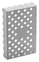
BMI-S-202-C
Shield, EMI, Surface Mount, 16.5 mm x 16.5 mm x 3.6 mm
⚠️ Reference pricing provided. In case of supply shortages, we will connect you with our trusted procurement partners to ensure your project's continuity.
- Manufacturer: LAIRD
- Product type: Shielding Gaskets & Material
- Depth: 3.6mm
- Width: 16.5mm
- Length: 16.5mm
- Shielding Type: EMI Shielding
| Delivery and price | |
|---|---|
| Units per pack | 56000 |
| Price | 0.678 € |
| Current stock | 1000+ |
| Lead time | 7 days |
Datasheet

**global solutions : local support ª**

| **Board Level Shields and Contacts**

www.lairdtech.com

**==> picture [135 x 58] intentionally omitted <==**

**Laird Technologies is the world-leader in the design and supply of customized performance-critical products for wireless and other advanced electronic applications. Laird Technologies partners with its customers to help find solutions for applications in various industries such as:**

**Network Equipment Telecommunications Data Communications Automotive Electronics Computers Aerospace Military Medical Equipment Consumer Electronics**

**Laird Technologies offers its customers unique product solutions, dedication to research and development and a seamless network of manufacturing and customer support facilities located all across the globe.**

**==> picture [241 x 44] intentionally omitted <==**

www.lairdtech.com

www.lairdtech.com

**TABLE OF CONTENTS**

## **INTRODUCTION TO BOARD LEVEL SHIELDS AND CONTACTS**

**==> picture [239 x 80] intentionally omitted <==**

**----- Start of picture text -----**<br>
|||
|---|---|
|Board Level Shields and Contacts .  .  .  .  .  .  .  .  .  .  .  .  .  .  .  .  .  .  .  .  .  .|2|
|Design Engineering  .  .  .  .  .  .  .  .  .  .  .  .  .  .  .  .  .  .  .  .  .  .  .  .  .  .  .  .  .  .  .  .|2|
|Prototyped Parts  .  .  .  .  .  .  .  .  .  .  .  .  .  .  .  .  .  .  .  .  .  .  .  .  .  .  .  .  .  .  .  .  .  .|2|
|Packaging Automation .  .  .  .  .  .  .  .  .  .  .  .  .  .  .  .  .  .  .  .  .  .  .  .  .  .  .  .  .  .|2|
|Quality ISO 9001:2000 Certified  .  .  .  .  .  .  .  .  .  .  .  .  .  .  .  .  .  .  .  .  .  .|2|
|RoHS Statement  .  .  .  .  .  .  .  .  .  .  .  .  .  .  .  .  .  .  .  .  .  .  .  .  .  .  .  .  .  .  .  .  .  .  .2|

**----- End of picture text -----**<br>


## **STANDARD DESIGN SHIELDS AND CONTACTS**

**==> picture [239 x 463] intentionally omitted <==**

**----- Start of picture text -----**<br>
|||
|---|---|
|97-2000 Shields (Series 97-2000)  .  .  .  .  .  .  .  .  .  .  .  .  .  .  .  .  .  .  .  .  .|3|
|Printed Circuit Board Shields (Series 97-860, 866, 870)  .  .  .  .  .|5|
|Standard Surface Mount Shields One-Piece and Two-Piece .  .  .  .  .|6|
|Part No . BMIS-101 and 201  .  .  .  .  .  .  .  .  .  .  .  .  .  .  .  .  .|7|
|Part No . BMIS-102 and 202  .  .  .  .  .  .  .  .  .  .  .  .  .  .  .  .  .|8|
|Part No . BMIS-103 and 203  .  .  .  .  .  .  .  .  .  .  .  .  .  .  .  .  .|9|
|Part No . BMIS-104 and 204  .  .  .  .  .  .  .  .  .  .  .  .  .  .  .  .|10|
|Part No . BMIS-105 and 205  .  .  .  .  .  .  .  .  .  .  .  .  .  .  .  .|11|
|Part No . BMIS-106 and 206  .  .  .  .  .  .  .  .  .  .  .  .  .  .  .  .|12|
|Part No . BMIS-107 and 207  .  .  .  .  .  .  .  .  .  .  .  .  .  .  .  .|13|
|Part No . BMIS-208  .  .  .  .  .  .  .  .  .  .  .  .  .  .  .  .  .  .  .  .  .  .  .|14|
|Part No . BMIS-209  .  .  .  .  .  .  .  .  .  .  .  .  .  .  .  .  .  .  .  .  .  .  .|14|
|Part No . BMIS-210  .  .  .  .  .  .  .  .  .  .  .  .  .  .  .  .  .  .  .  .  .  .  .|15|
|EZ PeelTM Standard Shields  .  .  .  .  .  .  .  .  .  .  .  .  .  .  .  .  .  .  .  .  .  .  .  .  .  .|16|
|Part No . 97-2002  .  .  .  .  .  .  .  .  .  .  .  .  .  .  .  .  .  .  .  .  .  .  .  .|17|
|Part No . 97-2003  .  .  .  .  .  .  .  .  .  .  .  .  .  .  .  .  .  .  .  .  .  .  .  .|17|
|Part No . 97-2004  .  .  .  .  .  .  .  .  .  .  .  .  .  .  .  .  .  .  .  .  .  .  .  .|17|
|Part No . 97-2005  .  .  .  .  .  .  .  .  .  .  .  .  .  .  .  .  .  .  .  .  .  .  .  .|17|
|Standard Precision Electronic Contacts   .  .  .  .  .  .  .  .  .  .  .  .  .  .  .  .|18|
|Part No . BMIC-001  .  .  .  .  .  .  .  .  .  .  .  .  .  .  .  .  .  .  .  .  .  .  .|18|
|Part No . BMIC-002  .  .  .  .  .  .  .  .  .  .  .  .  .  .  .  .  .  .  .  .  .  .  .|18|
|Part No . BMIC-004  .  .  .  .  .  .  .  .  .  .  .  .  .  .  .  .  .  .  .  .  .  .  .|18|
|Part No . BMIC-006  .  .  .  .  .  .  .  .  .  .  .  .  .  .  .  .  .  .  .  .  .  .  .|19|
|Part No . BMIC-007-01 .  .  .  .  .  .  .  .  .  .  .  .  .  .  .  .  .  .  .  .  .|19|
|Part No . BMI-C-010-*  .  .  .  .  .  .  .  .  .  .  .  .  .  .  .  .  .  .  .  .  .|19|
|CUSTOM DESIGN SHIELDS AND CONTACTS|
|Introduction .  .  .  .  .  .  .  .  .  .  .  .  .  .  .  .  .  .  .  .  .  .  .  .  .  .  .  .  .  .  .  .  .  .  .  .  .|20|
|One-Piece Shield Design  .  .  .  .  .  .  .  .  .  .  .  .  .  .  .  .  .  .  .  .  .  .  .  .  .  .  .|20|
|Two-Piece Shield Design  .  .  .  .  .  .  .  .  .  .  .  .  .  .  .  .  .  .  .  .  .  .  .  .  .  .  .|20|
|EZ PeelTM Shield Design .  .  .  .  .  .  .  .  .  .  .  .  .  .  .  .  .  .  .  .  .  .  .  .  .  .  .  .  .|21|
|Multi-Compartmental Shield Design   .  .  .  .  .  .  .  .  .  .  .  .  .  .  .  .  .  .|21|
|Drawn Board Level Shields (Series 97-2100)  .  .  .  .  .  .  .  .  .  .  .  .|21|
|Custom Precision Electronic Contacts   .  .  .  .  .  .  .  .  .  .  .  .  .  .  .  .  .|22|

**----- End of picture text -----**<br>


Products/specifications are subject to change.  Please contact Laird Technologies for potential changes in product specifications.

**www.lairdtech.com 1**

**INTRODUCTION TO BOARD LEVEL SHIELDS AND CONTACTS**

## **BOARD LEVEL SHIELDS AND CONTACTS**

Laird Technologies one-piece shields, multi-compartmental shields and precision contacts are designed to maximize performance in a minimum timeframe . Metal electronic components are packaged for surface mount applications suitable for a variety of industries .  Laird Technologies expertise is in numerous key divisions to ensure each part optimizes individual applications . Here's how we help you succeed:

## **DESIGN ENGINEERING**

Before contacting a Laird Technologies engineer, determine the right board level shield or contact design for the application . Based upon specifications, Laird Technologies experts will use the latest Pro-Engineering/AutoCAD systems to develop part designs in hours . Drawing upon extensive experience with application engineering, advanced design and materials engineering, Laird Technologies engineers will solve the most complex board level shield and contact problems .

Laird Technologies engineers and technical specialists look beyond the initial component to the entire application . Each engineer will create the ideal finished product at the best value . Example considerations include board layout, EMI shielding requirements and grounding terminations .

## **FAST TURNAROUND ON PROTOTYPES**

Accuracy and speed in the prototyping process are crucial in creating a successful product . Laird Technologies staff quickly responds within days with a prototyped part . By manufacturing with precision, the prototype meets the tolerances of a progressive die manufacturing production environment .

If design modifications are necessary, Laird Technologies prototype department is flexible and will address changes without affecting the delivery of the prototyped part . To ensure parts are delivered at optimum performance and meet specifications, all prototyped parts are 100% inspected on critical dimensions .

Laird Technologies also provides pre-production support to help get the production line up and running quickly . Parts designed in pre-production can be supplied while progressive die tools are being produced .

With manufacturing plants throughout North America, Asia and Europe Laird Technologies provides worldwide access to parts and offers the capacity to handle any size job .

## **PACKAGING AUTOMATION**

For innovations in packaging and in shield assemblies, a dedicated in-house automation engineering department routinely develops new automation technologies .  An array of packaging options is available for shields and contacts, including tape and reel, tray, tube and bulk . Laird Technologies tape and reel packaging allows for the lowest installed cost and is Electronic Industries Association (EIA) 481 compliant . Tape sizes are supplied on 13-inch and15-inch diameter reels . A transparent cover tape allows component verification and inspection without having to remove or handle components .

Two-piece shields, including multi-compartmental shields, are packaged as either assembled or unassembled parts .

Laird Technologies innovative automation engineering allows engineers to design small and complex contacts requiring pick-up zones of 1 mm and weighing less than 0 .01 grams . Custom automation equipment places the miniature contacts into tape pockets quickly and cost effectively . The tape and reel packaged parts are ready for installation onto printed circuit boards using standard pick-and-place equipment .

Vision recognition marks, such as holes and tabs, can orient parts . This eliminates an added step and leads to faster production . Laird Technologies ensures each design has an adequate pick-up area for pick-and-place equipment, without sacrificing performance .

## **QUALITY-ISO 9001:2000 CERTIFIED**

By placing a premium on quality, Laird Technologies has received the highest ratings on major customer qualification audits . Customers continually rank Laird Technologies among one of the top suppliers for quality and performance . The board level shield and contact facilities are ISO 9001:2000 certified by TUV-America Inc .

Built-in quality systems, including Laird Technologies proprietary 100% automated co-planarity inspection for board level shields, ensures rigid standards are met through all stages of operations (design, production, shipping, as well as prompt customer concern resolution) .

Laird Technologies executes real-time, automated SPC on all critical dimensions throughout production . By taking these measurements, quality assurance technicians can make necessary adjustments on the spot to ensure quality parts are on schedule . Maintaining traceability with SPC results for all jobs; captured data includes operator, shift, raw material, job number, work center and more . Additionally, non-contact, automated coordinate measuring machines (CMM) are located throughout Laird Technologies factory floors .

## **RoHS Statement**

All products in this catalog, along with all other Board Level Shield products are compliant to the RoHS standards .

**2 www.lairdtech.com**

**STANDARD DESIGN SHIELDS AND CONTACTS**

## **97-2000 SHIELDS**

## **Range of Pin and Pad Mounting Styles Maximizes Flexibility**

The 97-2000 series allows mounting options including various pin styles for through-hole mounting or pad styles for surface mounting . The frame material forms the walls of the enclosure and the cover is held securely in place by spring force alone . Covers can be easily removed and replaced to provide access to components . Large or small quantities are easily manufactured using automated tooling, short run capabilities or photochemical machining operations .

- 97-2000 frame heights from 0 .130" (3,0 mm) to 1" (25,4 mm), with other heights available upon request

- Cover design permits retention even when severe shock or vibration are a

- consideration; cover designed for easy removal and replacement

- Design allows for automated pick-and-place operations

- Locking feature on frame guarantees corner joint stability

- Variety of pin style options available including a surface mountable style

- Pin location can be customized to hole location or a defined pitch

- Frames can be hand-formed or supplied formed and with cover assembled

- • A modified pin style is available for extra retention in through hole

- application

- All parts are treated as custom, so standards exist

- RoHS compliant

**^**[Test performance in accordance with MIL-STD-285 using an aperture the same size ] as the 1-3/4" x 2" (44,5 mm x 5,08 mm) PC shield as reference . Measurement below 400 MHz were not possible because of the aperture attenuation .

## **97-2000 SHIELDS**

**Frame Height and Pin Option**

**==> picture [230 x 75] intentionally omitted <==**

**----- Start of picture text -----**<br>
PIN STYLE 1.<br>Through Hole with Standoff<br>.130 to 1.000<br>H (3,3 to 25,4)<br>Under Cover<br>Height Range<br>**----- End of picture text -----**<br>


**==> picture [220 x 180] intentionally omitted <==**

**----- Start of picture text -----**<br>
FIGURE 1.<br>Hole Pattern Layout<br>fe)<br>°.<br>Pitch<br>Oo<br>°<br>, 5<br>55<br>® 1/2 Pitch<br>+ 0.006<br>1/2 Pitch<br>+ 0.006<br>**----- End of picture text -----**<br>


(Consult engineering for irregular hole patterns .)

All dimensions shown are in inches (millimeters) unless otherwise specified .

**www.lairdtech.com 3**

**STANDARD DESIGN SHIELDS AND CONTACTS**

## **PIN STYLE 2.**

**==> picture [38 x 6] intentionally omitted <==**

**----- Start of picture text -----**<br>
PIN STYLE 3.<br>**----- End of picture text -----**<br>


**==> picture [56 x 66] intentionally omitted <==**

**----- Start of picture text -----**<br>
Surface Mount Tab<br>.130 to 1.000<br>(3,3 to 25,4)<br>Under Cover<br>Height Range<br>**----- End of picture text -----**<br>


**==> picture [92 x 64] intentionally omitted <==**

**----- Start of picture text -----**<br>
Through Hole<br>.130 to 1.000<br>(3,3 to 25,4)<br>H Under Cover<br>Height Range<br>**----- End of picture text -----**<br>


**FIGURE 2.**

**==> picture [215 x 119] intentionally omitted <==**

**----- Start of picture text -----**<br>
Pitch Selection Placement and Corner Locking Feature<br>.130 to 1.000<br>(3,3 to 25,4)<br>Under Cover<br>Height Range<br>Any pitch (P) with minimum<br>of .200 (5,08)<br>**----- End of picture text -----**<br>


**==> picture [246 x 131] intentionally omitted <==**

**----- Start of picture text -----**<br>
FIGURE 3.<br>Cover Detail<br>Standard cover material thickness 0.010" (0,25 mm) tin plated<br>phosphor bronze, in coated steel or stainless steel<br>eM IOOUOToD.  : ECE: : Hf ANT (2,97)<br>Phantom<br>lines indicate  05 (1,27) — fl<br>optional   |<br>L-shaped   Type on<br>configuration I bs 2, I. random<br>| ye |! locations<br>**----- End of picture text -----**<br>


## **PIN STYLE 4.**

**==> picture [114 x 59] intentionally omitted <==**

**----- Start of picture text -----**<br>
Flush Surface Mount<br>.130 to 1.000<br>H (3,3 to 25,4)<br>Under Cover<br>Height Range<br>**----- End of picture text -----**<br>


All dimensions shown are in inches (millimeters) unless otherwise specified .

**4 www.lairdtech.com**

**STANDARD DESIGN SHIELDS AND CONTACTS**

## **High-Performance, Readily Available**

Laird Technologies standard board level shields and contacts offer readily available, low-cost EMI shield and contact alternatives to custom designed solutions . A variety of sizes and designs are available to choose from, so finding a product that delivers the desired results for a project is easy . Modifications are an option if the standard product does not fully fit space requirement constraints .

Laird Technologies standard shields and contacts are available in a range of material choices, and all allow for full solderability . Standard shield offerings incorporate proprietary design criteria for maximum performance and are available in one-piece and two-piece designs . Laird Technologies standard contacts base materials include beryllium copper, phosphor bronze, nickel and stainless steel . Many plating options are offered for maximum electrical current carrying performance .

## **PRINTED CIRCUIT BOARD SHIELDS**

**==> picture [219 x 112] intentionally omitted <==**

**----- Start of picture text -----**<br>
97-860<br>ey) <<br>97-866<br>ny, “yy<br>Patent No. 4,754,101 97-870<br>**----- End of picture text -----**<br>


## **PC SHIELD DIMENSIONS**

|SERIES|A|B|C|D|E|APPROX .<br>LENGTH<br>FT (M)|
|---|---|---|---|---|---|---|
|97-860|.520<br>(13,2)|.045<br>(1,1)|.120<br>(3,2)|.030<br>(0,8)|.400<br>(10,2)|25<br>(7,6)|
|97-866|.820<br>(20,8)|.045<br>(1,1)|.120<br>(3,2)|.030<br>(0,8)|.700<br>(17,8)|25<br>(7,6)|
|97-870|1 .120<br>(28,4)|.045<br>(1,1)|.120<br>(3,2)|.030<br>(0,8)|1 .00<br>(25,4)|25<br>(7,6)|


**Front View 97-860 and 97-866 25 ft. (7,6 m)** Ynys **.200 (5,08) .115 Dia. (2,92) Typ. Clearance**

Other heights and custom-designed cover configurations available . Consult sales department .

## **Typical Mounting Configuration**

**==> picture [510 x 148] intentionally omitted <==**

**----- Start of picture text -----**<br>
Flat Cover [°°]<br>Front View 97-870 Side View Nominal Cover<br>Thickness-Any<br>Conductive Material<br>25 ft. (7,6 m) D<br>.020 (0,51)<br>.300 (7,62)<br>Spring Finger B<br>Standard Strip<br>A E<br>Solder Tab WwCFA == — = = = = — | |<br>Mounting Pin<br>~S, C<br>Mount<br>4. .300 (7,62) -—— Hole<br>Centerline<br>**----- End of picture text -----**<br>


All dimensions shown are in inches (millimeters) unless otherwise specified .

**www.lairdtech.com 5**

**STANDARD DESIGN SHIELDS AND CONTACTS**

## **STANDARD SURFACE MOUNT SHIELDS ONE-PIECE Off the Shelf, On Spec and On Budget**

One-piece standard surface mount shields offer six sides of protection, with the sixth side being the board itself . One-piece designs offer economical shielding protection where access to covered components is not necessary . There are no tooling costs associated with either the one and/or two-piece design .

## **STANDARD SURFACE MOUNT SHIELDS TWO-PIECE**

## **Reduce Board Damage From Inspection and Repairs**

Two-piece standard surface mount shields offer users the flexibility to inspect or repair shielded components without risking board damage by removing the entire shield or incurring tooling costs . Covers snap on and off with ease, which makes repair of the component under the shield quicker and easier and reduces board re-work . Two-piece shields are available unassembled* and are designed to survive drop, shock and no-rattle tests .

*Pre-assembly is an option . Consult sales .

## **STANDARD ONE-PIECE BOARD LEVEL SHIELDS**

|PART<br>NUMBER<br>MAXIMUM<br>OVERALL<br>LENGTH<br>MAXIMUM<br>OVERAL<br>WIDTH<br>MAXIMUM<br>OVERALL<br>HEIGHT<br>CARRIER<br>TAPE<br>WIDTH<br>CARRIER<br>TAPE<br>PITCH<br>PARTS<br>PER REEL<br>WEIGHT<br>BMI-S-101<br>.538<br>(13,66)<br>.476<br>(12,10)<br>.100<br>(2,54)<br>24 mm<br>20 mm<br>1000<br>0 .4 g<br>BMI-S-102<br>.650<br>(16,50)<br>.650<br>(16,50)<br>.142<br>(3,60)<br>32 mm<br>24 mm<br>700<br>0 .7 g<br>~~Pt tt tt~~<br>~~re~~<br>~~ee~~<br>~~ee~~<br>~~eee~~|
|---|
|BMI-S-103<br>1 .032<br>(26,21)<br>1 .032<br>(26,21)<br>.200<br>(5,08)<br>44 mm<br>32 mm<br>300<br>1 .6 g<br>BMI-S-104<br>1 .260<br>(32,00)<br>1 .260<br>(32,00)<br>.236<br>(6,00)<br>44 mm<br>36 mm<br>225<br>2 .4 g<br>BMI-S-106<br>1 .450<br>(36,83)<br>1 .326<br>(33,68)<br>.200<br>(5,08)<br>56 mm<br>40 mm<br>300<br>2 .4 g<br>BMI-S-105<br>1 .500<br>(38,10)<br>1 .000<br>(25,40)<br>.236<br>(6,00)<br>56 mm<br>32 mm<br>250<br>2 .5 g<br>BMI-S-107<br>1 .747<br>(44,37)<br>1 .747<br>(44,37)<br>.384<br>(9,75)<br>56 mm<br>56 mm<br>120<br>6 .5 g<br>~~ee~~<br>~~ee~~<br>~~ee ee~~<br>~~eeeee~~<br>~~ee ee~~<br>~~eeeee~~<br>~~ee~~<br>~~ee ee~~<br>~~ee~~<br>~~ee~~<br>~~ee ee ee~~<br>~~ee~~<br>~~ee~~|
|**STANDARD TWO-PIECE BOARD LEVEL SHIELD FRAMES**<br>PART<br>NUMBER<br>OVERALL<br>LEGNTH<br>OVERALL<br>WIDTH<br>OVERALL<br>HEIGHT<br>TAPE<br>WIDTH<br>TAPE<br>PITCH<br>PARTS PER<br>REEL<br>BMI-S-201-F<br>.538<br>(13,66)<br>.476<br>(12,10)<br>.100<br>(2,54)<br>24 mm<br>20 mm<br>1000<br>BMI-S-202-F<br>.650<br>(16,50)<br>.650<br>(16,50)<br>.142<br>(3,60)<br>32 mm<br>24 mm<br>700<br>BMI-S-203-F<br>1 .032<br>(26,21)<br>1 .032<br>(26,21)<br>.200<br>(5,08)<br>44 mm<br>32 mm<br>300<br>BMI-S-209-F<br>1 .156<br>(29,36)<br>.728<br>(32,00)<br>.275<br>(7,00)<br>56 mm<br>28 mm<br>400<br>BMI-S-204-F<br>1 .260<br>(32,00)<br>1 .260<br>(32,00)<br>.236<br>(6,00)<br>44 mm<br>36 mm<br>225<br>BMI-S-206-F<br>1 .450<br>(36,83)<br>1 .326<br>(33,68)<br>.200<br>(5,08)<br>56 mm<br>40 mm<br>300<br>BMI-S-205-F<br>1 .500<br>(38,10)<br>1 .000<br>(25,40)<br>.236<br>(6,00)<br>56 mm<br>44 mm<br>250<br>BMI-S-210-F<br>1 .732<br>(44,02)<br>1 .201<br>(30,50)<br>.118<br>(3,00)<br>56 mm<br>40 mm<br>450<br>BMI-S-207-F<br>1 .747<br>(44,37)<br>1 .747<br>(44,37)<br>.384<br>(9,75)<br>56 mm<br>56 mm<br>120<br>BMI-S-208-F<br>1 .559<br>(39,60)<br>1 .559<br>(39,60)<br>.276<br>(7,00)<br>56 mm<br>48 mm<br>200<br>~~P|~~<br>~~|TT~~<br>~~a~~<br>~~ee eeeee~~<br>~~ee ee eeee~~<br>~~a~~<br>~~ee eeeee~~<br>~~ee ee eeeee~~<br>~~ee ee eeeee~~<br>~~ee ee eeeee~~<br>~~ee ee eeeee~~<br>~~ee eeee~~<br>~~ee ee~~<br>~~ee ee~~<br>~~ee~~<br>~~eeeeee~~<br>~~ee~~<br>~~ee~~|


## **TYPICAL PROPERTIES & PERFORMANCE - ALL PART NUMBERS**

|PROPERTY|TEST METHOD|RESULT|
|---|---|---|
|Co-planarity|LTWI-1119|<0,10 mm|
|Solderability|ANSI/JSTD-002|>99%|
|Solderability|MIL-STD-202 Method 208|>99%|
|Adhesion|ASTM B-571|Passes|
|3 Axis Mechanical Shock|LTES-461|Passes|


## **DESIGN PARAMETERS - ALL PART NUMBERS**

|PICK-UP SPOT<br>DIAMETER|MATERIAL|MATERIAL THICKNESS|CARRIER TAPE<br>MATERIAL|
|---|---|---|---|
|6 mm or greater|0,20 mm CRS Tin|0,20 mm|LTIMS-LCB|
|Cover tape material|REEL DIAMETER|REEL MATERIAL|PACKAGING|
|LTIMS-PSA|330 mm (101, 102, 103,<br>104, 201 202 203 204)<br>381 mm (105, 106, 107,<br>205, 206, 207, 208,<br>209, 210)|Plastic|EIA-481|


All dimensions shown are in inches (millimeters) unless otherwise specified .

**6 www.lairdtech.com**

## **STANDARD DESIGN SHIELDS AND CONTACTS**

## **STANDARD SURFACE MOUNT SHIELD ONE-PIECE**

## **DESIGN SPECIFICATIONS**

|PART<br>NUMBER|MAXIMUM<br>OVERALL<br>DIMENSION|MAXIMUM<br>OVERALL<br>HEIGHT|CARRIER TAPE<br>WIDTH|CARRIER TAPE<br>PITCH|PARTS PER<br>REEL|
|---|---|---|---|---|---|
|BMI-S-101|.538 x  .476<br>(13,66 x 12,70)|.100<br>(2,54)|24 mm|20 mm|1000|


## **APPLICATIONS:**

- Works exceptionally well in small component areas

- 48 VQFP

## **Dimensions (mm)**

**==> picture [151 x 52] intentionally omitted <==**

**----- Start of picture text -----**<br>
Footprint<br>1,00<br>ts<br>Carrier Tape<br>**----- End of picture text -----**<br>


## **STANDARD SURFACE MOUNT SHIELD TWO-PIECE**

## **DESIGN SPECIFICATIONS**

## **APPLICATIONS:**

- Works exceptionally well in small component areas • 48 VQFP

|PART<br>NUMBER|MAXIMUM<br>OVERALL<br>DIMENSION|MAXIMUM<br>OVERALL<br>HEIGHT|CARRIER TAPE<br>WIDTH|CARRIER TAPE<br>PITCH|PARTS PER<br>REEL|
|---|---|---|---|---|---|
|BMI-S-201-F|.538 x  .476<br>(13,66 x 12,70)|.100<br>(2,54)|24 mm|20 mm|1000|


The cover is ordered as a separate part .  The part number is BMI-S-201-C and is packaged in the same quantity as the frame .

## **Dimensions (mm)**

**==> picture [31 x 103] intentionally omitted <==**

**----- Start of picture text -----**<br>
Footprint<br>Carrier Tape<br>**----- End of picture text -----**<br>


**www.lairdtech.com 7**

**STANDARD DESIGN SHIELDS AND CONTACTS**

## **STANDARD SURFACE MOUNT SHIELD ONE-PIECE PART NO. BMI-S-102**

## **DESIGN SPECIFICATIONS**

|PART<br>NUMBER|MAXIMUM<br>OVERALL<br>DIMENSION|MAXIMUM<br>OVERALL<br>HEIGHT|CARRIER TAPE<br>WIDTH|CARRIER TAPE<br>PITCH|PARTS PER REEL|**APPLICATIONS:**<br>•48 VQFP<br>•44, 48 QFP|
|---|---|---|---|---|---|---|
|BMI-S-102|.650 x  .650<br>(16,50 x 16,50)|.142<br>(3,60)|32 mm|24 mm|700||
|**Dimensions (mm)**|||||||


**==> picture [173 x 47] intentionally omitted <==**

**----- Start of picture text -----**<br>
Footprint<br>us<br>== Carrier Tape<br>**----- End of picture text -----**<br>


## **STANDARD SURFACE MOUNT SHIELD TWO-PIECE PART NO. BMI-S-202**

## **DESIGN SPECIFICATIONS**

|PART<br>NUMBER|MAXIMUM<br>OVERALL<br>DIMENSION|MAXIMUM<br>OVERALL<br>HEIGHT|CARRIER TAPE<br>WIDTH|CARRIER TAPE<br>PITCH|PARTS PER<br>REEL|
|---|---|---|---|---|---|
|BMI-S-202-F|.650 x  .650<br>(16,50 x 16,50)|.142<br>(3,60)|32 mm|24 mm|700|


The cover is ordered as a separate part .  The part number is BMI-S-202-C and is packaged in the same quantity as the frame .

## **Dimensions (mm)**

**==> picture [31 x 103] intentionally omitted <==**

**----- Start of picture text -----**<br>
Footprint<br>Carrier Tape<br>**----- End of picture text -----**<br>


**8 www.lairdtech.com**

## **STANDARD DESIGN SHIELDS AND CONTACTS**

## **STANDARD SURFACE MOUNT SHIELD ONE-PIECE**

## **DESIGN SPECIFICATIONS**

|PART<br>NUMBER|MAXIMUM<br>OVERALL<br>DIMENSION|MAXIMUM<br>OVERALL<br>HEIGHT|CARRIER<br>TAPE WIDTH|CARRIER<br>TAPE PITCH|PARTS PER<br>REEL|
|---|---|---|---|---|---|
|BMI-S-103|1 .032 x 1 .032<br>(26,21 x 26,21)|.200<br>(5,08)|44 mm|32 mm|300|


## **APPLICATIONS:**

- 32, 44, 52 pin PLCC

- 121, 169 BGA

- 48, 100 VQFP

- 44, 48, 64, 80 QFP

## **Dimensions (mm)**

Footprint

**==> picture [31 x 7] intentionally omitted <==**

**----- Start of picture text -----**<br>
Carrier Tape<br>**----- End of picture text -----**<br>


## **STANDARD SURFACE MOUNT SHIELD TWO-PIECE**

## **DESIGN SPECIFICATIONS**

|PART<br>NUMBER|MAXIMUM<br>OVERALL<br>DIMENSION|MAXIMUM<br>OVERALL<br>HEIGHT|CARRIER<br>TAPE WIDTH|CARRIER<br>TAPE PITCH|PARTS PER<br>REEL|
|---|---|---|---|---|---|
|BMI-S-203-F|1 .032 x 1 .032<br>(26,21 x 26,21)|.200<br>(5,08)|44 mm|32 mm|300|


The cover is ordered as a separate part .  The part number is BMI-S-203-C and is packaged in the same quantity as the frame .

## **APPLICATIONS:**

- 32, 44, 52 pin PLCC • 121, 169 BGA • 48, 100 VQFP

- 44, 48, 64, 80 QFP

## **Dimensions (mm)**

**==> picture [24 x 7] intentionally omitted <==**

**----- Start of picture text -----**<br>
Footprint<br>**----- End of picture text -----**<br>


**==> picture [62 x 20] intentionally omitted <==**

**----- Start of picture text -----**<br>
Carrier Tape<br>**----- End of picture text -----**<br>


**www.lairdtech.com 9**

**STANDARD DESIGN SHIELDS AND CONTACTS**

## **STANDARD SURFACE MOUNT SHIELD ONE-PIECE**

## **DESIGN SPECIFICATIONS**

|PART<br>NUMBER|MAXIMUM<br>OVERALL<br>DIMENSION|MAXIMUM<br>OVERALL<br>HEIGHT|CARRIER<br>TAPE WIDTH|CARRIER<br>TAPE PITCH|PARTS PER<br>REEL|
|---|---|---|---|---|---|
|BMI-S-104|1 .260 x 1 .260<br>(32,00 x 32,00)|.236<br>(6,00)|44 mm|36 mm|225|


## **APPLICATIONS:**

- 121, 169, 225 BGA • 32, 44, 52, 68 PLCC • 48, 100 VQFP • 44, 48, 64, 80, 100 QFP

## **Dimensions (mm)**

**==> picture [171 x 50] intentionally omitted <==**

**----- Start of picture text -----**<br>
Footprint<br>Carrier Tape<br>**----- End of picture text -----**<br>


## **APPLICATIONS:**

## **STANDARD SURFACE MOUNT SHIELD TWO-PIECE**

|**TWO-PIECE**|**TWO-PIECE**|||||•121, 169, 225 BGA|
|---|---|---|---|---|---|---|
|**DESIGN SPECIFICATIONS**<br>PART<br>NUMBER<br>MAXIMUM<br>OVERALL<br>DIMENSION||MAXIMUM<br>OVERALL<br>HEIGHT|CARRIER<br>TAPE WIDTH|CARRIER<br>TAPE PITCH|PARTS PER<br>REEL|•32, 44, 52, 68 PLCC<br>•48, 100 VQFP<br>•44, 48, 64, 80, 100 QFP|
|BMI-S-204-F|1 .260 x 1 .260<br>(32,00 x 32,00)|.236<br>(6,00)|44 mm|36 mm|225||


## **DESIGN SPECIFICATIONS**

The cover is ordered as a separate part .  The part number is BMI-S-204-C and is packaged in the same quantity as the frame .

## **Dimensions (mm)**

**==> picture [24 x 8] intentionally omitted <==**

**----- Start of picture text -----**<br>
Footprint<br>**----- End of picture text -----**<br>


**==> picture [32 x 8] intentionally omitted <==**

**----- Start of picture text -----**<br>
Carrier Tape<br>**----- End of picture text -----**<br>


**10 www.lairdtech.com**

## **STANDARD DESIGN SHIELDS AND CONTACTS**

## **STANDARD SURFACE MOUNT SHIELD ONE-PIECE**

## **DESIGN SPECIFICATIONS**

|PART<br>NUMBER|MAXIMUM<br>OVERALL<br>DIMENSION|MAXIMUM<br>OVERALL<br>HEIGHT|CARRIER<br>TAPE WIDTH|CARRIER<br>TAPE PITCH|PARTS PER<br>REEL|
|---|---|---|---|---|---|
|BMI-S-105|1 .500 x 1 .000<br>(38,10 x 25,40)|.236<br>(6,00)|56 mm|32 mm|250|


## **APPLICATIONS:**

- 121 BGA

- 32, 44, 52 PLCC

- 48, 100 VQFP

- 44, 48, 64, 80, 100 QFP

## **Dimensions (mm)**

**==> picture [159 x 52] intentionally omitted <==**

**----- Start of picture text -----**<br>
Footprint<br>-<br>bs og<br>Carrier Tape<br>0<br>**----- End of picture text -----**<br>


## **STANDARD SURFACE MOUNT SHIELD TWO-PIECE PART NO. BMI-S-205**

## **DESIGN SPECIFICATIONS**

|PART<br>NUMBER|MAXIMUM<br>OVERALL<br>DIMENSION|MAXIMUM<br>OVERALL<br>HEIGHT|CARRIER<br>TAPE WIDTH|CARRIER<br>TAPE PITCH|PARTS PER<br>REEL|
|---|---|---|---|---|---|
|BMI-S-205-F|1 .500 x 1 .000<br>(38,10 x 25,40)|.236<br>(6,00)|56 mm|44 mm|250|


The cover is ordered as a separate part .  The part number is BMI-S-205-C and is packaged in the same quantity as the frame .

## **APPLICATIONS:**

- 121 BGA

- 32, 44, 52 PLCC

- 48, 100 VQFP • 44, 48, 64, 80, 100 QFP

## **Dimensions (mm)**

**==> picture [24 x 7] intentionally omitted <==**

**----- Start of picture text -----**<br>
Footprint<br>**----- End of picture text -----**<br>


**==> picture [97 x 15] intentionally omitted <==**

**----- Start of picture text -----**<br>
HVogGaogoaooooooogoooNoNogS Carrier Tape<br>**----- End of picture text -----**<br>


**www.lairdtech.com 11**

**STANDARD DESIGN SHIELDS AND CONTACTS**

## **STANDARD SURFACE MOUNT SHIELD ONE-PIECE PART NO. BMI-S-106**

## **DESIGN SPECIFICATIONS**

|PART<br>NUMBER|MAXIMUM<br>OVERALL<br>DIMENSION|MAXIMUM<br>OVERALL<br>HEIGHT|CARRIER<br>TAPE WIDTH|CARRIER<br>TAPE PITCH|PARTS PER<br>REEL|
|---|---|---|---|---|---|
|BMI-S-106|1 .450 x 1 .326<br>(36,83 x 33,68)|.200<br>(5,08)|56 mm|40 mm|300|


## **APPLICATIONS:**

- 121, 169, 225 BGA

- 32, 44, 52, 68 PLCC

- 48, 100 VQFP

- 44, 48, 64, 80, 100 QFP

## **Dimensions (mm)**

**==> picture [24 x 8] intentionally omitted <==**

**----- Start of picture text -----**<br>
Footprint<br>**----- End of picture text -----**<br>


**==> picture [31 x 7] intentionally omitted <==**

**----- Start of picture text -----**<br>
Carrier Tape<br>**----- End of picture text -----**<br>


## **STANDARD SURFACE MOUNT SHIELD TWO-PIECE PART NO. BMI-S-206**

## **DESIGN SPECIFICATIONS**

|PART<br>NUMBER|MAXIMUM<br>OVERALL<br>DIMENSION|MAXIMUM<br>OVERALL<br>HEIGHT|CARRIER<br>TAPE WIDTH|CARRIER<br>TAPE PITCH|PARTS PER<br>REEL|
|---|---|---|---|---|---|
|BMI-S-206-F|1 .450 x 1 .326<br>(36,83 x 33,68)|.200<br>(5,08)|56 mm|40 mm|300|


The cover is ordered as a separate part .  The part number is BMI-S-206-C and is packaged in the same quantity as the frame .

## **APPLICATIONS:**

- 121, 169, 225 BGA

- 32, 44, 52, 68 PLCC

- 48, 100 VQFP • 44, 48, 64, 80, 100 QFP

## **Dimensions (mm)**

**==> picture [24 x 7] intentionally omitted <==**

**----- Start of picture text -----**<br>
Footprint<br>**----- End of picture text -----**<br>


**==> picture [31 x 23] intentionally omitted <==**

**----- Start of picture text -----**<br>
Carrier Tape<br>-<br>**----- End of picture text -----**<br>


**12 www.lairdtech.com**

## **STANDARD DESIGN SHIELDS AND CONTACTS**

## **STANDARD SURFACE MOUNT SHIELD ONE-PIECE BMI-S-107**

## **DESIGN SPECIFICATIONS**

## **APPLICATIONS:**

|PART<br>NUMBER|MAXIMUM<br>OVERALL<br>DIMENSION|MAXIMUM<br>OVERALL<br>HEIGHT|CARRIER<br>TAPE WIDTH|CARRIER<br>TAPE PITCH|PARTS PER<br>REEL|
|---|---|---|---|---|---|
|BMI-S-107|1 .747 x 1 .747<br>(44,37 x 44,37)|.384<br>(9,75)|56 mm|56 mm|120|


- Supplied in 56 mm EIA standard carrier tape

- 121, 169, 225, 313 BGA

- 32, 44, 52, 68, 84 PLCC

- 48, 100, 208 VQFP

## **Dimensions (mm)**

- 44, 48, 64, 80, 100, 120, 160 QFP

**==> picture [24 x 7] intentionally omitted <==**

**----- Start of picture text -----**<br>
Footprint<br>**----- End of picture text -----**<br>


**==> picture [78 x 23] intentionally omitted <==**

**----- Start of picture text -----**<br>
Carrier Tape<br> NOOO ONOOO0O0000eG<br>**----- End of picture text -----**<br>


## **STANDARD SURFACE MOUNT SHIELD TWO-PIECE BMI-S-207**

**==> picture [83 x 7] intentionally omitted <==**

**----- Start of picture text -----**<br>
DESIGN SPECIFICATIONS<br>**----- End of picture text -----**<br>


## **APPLICATIONS:**

- 121, 169, 225, 313 BGA

- 32, 44, 52, 68, 84 PLCC

|PART<br>NUMBER<br>MAXIMUM<br>OVERALL<br>DIMENSION<br>MAXIMUM<br>OVERALL<br>HEIGHT<br>CARRIER<br>TAPE WIDTH<br>CARRIER<br>TAPE PITCH<br>PARTS PER<br>REEL<br>BMI-S-207-F<br>1 .747 x 1 .747<br>(44,37 x 44,37)<br>.384<br>(9,75)<br>56 mm<br>56 mm<br>120<br>The cover is ordered as a separate part .  The part number is BMI-S-207-C and is packaged in the same<br>quantity as the frame .<br>~~tft t—~~|•48, 100, 208 VQFP<br>•44, 48, 64, 80, 100, 120, 160 QFP|
|---|---|


## **Dimensions (mm)**

**==> picture [23 x 7] intentionally omitted <==**

**----- Start of picture text -----**<br>
Footprint<br>**----- End of picture text -----**<br>


**==> picture [104 x 17] intentionally omitted <==**

**----- Start of picture text -----**<br>
Carrier Tape<br>da0000000000000000000000008<br>**----- End of picture text -----**<br>


**www.lairdtech.com 13**

**STANDARD DESIGN SHIELDS AND CONTACTS**

## **STANDARD SURFACE MOUNT SHIELD TWO-PIECE BMI-S-208**

## **DESIGN SPECIFICATIONS**

|PART<br>NUMBER|MAXIMUM<br>OVERALL<br>DIMENSION|MAXIMUM<br>OVERALL<br>HEIGHT|CARRIER<br>TAPE WIDTH|CARRIER<br>TAPE PITCH|PARTS PER<br>REEL|
|---|---|---|---|---|---|
|BMI-S-208-F|1 .559 x 1 .559<br>(39,60 x 39,60)|.276<br>(7,00)|56 mm|48 mm|200|


The cover is ordered as a separate part .  The part number is BMI-S-208-C and is packaged in the same quantity as the frame .

## **Dimensions (mm)**

Footprint 1,00 TYP

**==> picture [292 x 182] intentionally omitted <==**

**----- Start of picture text -----**<br>
6,00<br>39,60  40,20<br>38,10<br>19,80 o<br>1,50<br>0,00 0,00<br>3 .00<br>0,50  7,00<br>TYP | _ 0,10<br>19,80 38,10  39,60 0,00 40,20<br>0,00 3,30 6,30 9,30 12,30 15,30 18,30 21,30 24,30 27,30 30,30 33,30 36,30<br>0,00  1,50<br>**----- End of picture text -----**<br>


**==> picture [337 x 146] intentionally omitted <==**

**----- Start of picture text -----**<br>
40,40<br>36,30<br>34,10<br>| 30,30<br>28,1024,30 5 1<br>: 1,50 x 2 22,10<br>18,30<br>16,10<br>0,00<br>12,30 TI l<br>10,106,30 7 l<br>4,10<br>0,00<br>TSARRAAAA<br>3 .00<br>0,00 40,20<br>0,00 4,10 6,30 10,10 12,30 16,10 18,30 22,10 24,30 28,10 30,30 34,10 36,30 40,40<br>**----- End of picture text -----**<br>


## **STANDARD SURFACE MOUNT SHIELD TWO-PIECE BMI-S-209**

## **DESIGN SPECIFICATIONS**

|PART<br>NUMBER|MAXIMUM<br>OVERALL<br>DIMENSION|MAXIMUM<br>OVERALL<br>HEIGHT|CARRIER<br>TAPE WIDTH|CARRIER<br>TAPE PITCH|PARTS PER<br>REEL|
|---|---|---|---|---|---|
|BMI-S-209-F|1 .156 x 0 .728<br>(29,36 x 18,50)|.275<br>(7,00)|44 mm|28 mm|400|


The cover is ordered as a separate part .  The part number is BMI-S-209-C and is packaged in the same quantity as the frame .

## **Dimensions (mm)**

Footprint

**==> picture [494 x 163] intentionally omitted <==**

**----- Start of picture text -----**<br>
Z 1,00<br>R0,25 x 4 X TYP<br>6,00 19,10<br>18,50 16,10 19,30<br>16,00 x 217,00 X Z 1,50 x 2 13,75<br>11,55<br>9,25 3,00<br>0,00 a 7,75 ae<br>2,50 x 2 5,55<br>1,50<br>0,00 0,00 Load<br>1 Ji Tl tl tlt<br>. 0,50<br>TYP<br>3,00<br>3,00<br>0,00 26,96 26,96<br>1,50 2,50 x 2 13,93 14,68 15,43 26,86 x 2 27,8629,36 0,00 4,98 7,18 10,98 13,18 16,98 19,18 22,98 25,18 30,16<br>0,00 2,98 x 2 5,73 8,98 x 2 11,73 14,98 x 2 17,73 20,98 x 2 23,73 26,98 x 2<br>0,00<br>**----- End of picture text -----**<br>


**14 www.lairdtech.com**

## **STANDARD DESIGN SHIELDS AND CONTACTS**

## **STANDARD SURFACE MOUNT SHIELD TWO-PIECE BMI-S-210**

## **DESIGN SPECIFICATIONS**

|PART<br>NUMBER|MAXIMUM<br>OVERALL<br>DIMENSION|MAXIMUM<br>OVERALL<br>HEIGHT|CARRIER<br>TAPE WIDTH|CARRIER<br>TAPE PITCH|PARTS PER<br>REEL|
|---|---|---|---|---|---|
|BMI-S-210-F|1 .732 x 1 .201<br>(44,00 x 30,50)|.118<br>(3,00)|56 mm|40 mm|120|


The cover is ordered as a separate part .  The part number is BMI-S-210-C and is packaged in the same quantity as the frame .

## **Dimensions (mm)**

**==> picture [146 x 118] intentionally omitted <==**

**----- Start of picture text -----**<br>
A B<br>31,10<br>28,10 a A B 27,55   x2<br>24,30<br>21,55  x2<br>18,30<br>Ee 15,55  x2<br>: 1,50   x2 12,30<br>9,55  x2<br>6,30<br>3,00 3,55  x2<br>0,00 - 0,00<br>ry<br>0,50 TYP 2,40<br>|TSPrErEerarids<br>3,00<br>0,00 41,60 44,60<br>0,00 4,30  x2 7,05 10,30  x2 13,05 16,30   x2 19,05 22,30   x2 25,05 28,30   x2 31,05 34,30   x2 37,05 40,30   x2<br>**----- End of picture text -----**<br>


**==> picture [181 x 157] intentionally omitted <==**

**----- Start of picture text -----**<br>
Footprint 1,00 TYP<br>31,30<br>2x  28,75<br>2X  26,55<br>2X  22,75 :<br>2X  20,55<br>2X  16,75<br>2X  14,55<br>—<br>2X  10,75<br>2X  8,55<br>2X  4,75 =<br>2X  2,55<br>0,00 Se eel<br>Eee<br>0,00 2X  3,30  2X  5,50 2X  9,30 2X  11,50 2X  15,30 2X  17,50 2X  21,30 2X  23,50 2X  27,30 2X  29,50 2X  33,30 2X  35,50 2X  39,30 2X  41,50 44,80<br>**----- End of picture text -----**<br>


**www.lairdtech.com 15**

**STANDARD DESIGN SHIELDS AND CONTACTS**

## **TM EZ PEEL STANDARD SHIELDS**

## **For Quick and Easy Access to Board Level Components**

Laird Technologies offers four standard sizes of EZ Peel removable cover board level shields . These patented shields have a solid top, scored to allow peel-off when access to board level components within the shield is required .

The peel-off feature prevents damage to the board and components by eliminating the need for labor intensive de-soldering, which often results in increased scrap . Peeling off the cover is accomplished by using a small starter hole for simple removal . This hand operation requires minimal force using a hook scriber or tweezers .

After repair, replacement or adjustment of internal components, the shield can be resealed using a replacement cover . Laird Technologies offers two replacement cover options: a snap-in cover and a dish cover .

The snap-in cover utilizes a lance and hole design . The replacement cover snaps into place and locks into a lance feature on the frame of the original shield .

The other option is a dish cover that gets soldered into place on the board . The dish shape allows for self-location of the cover for soldering . |

Standard EZ Peel board level shields can be packaged in tape and reel formats for easy SMT installation using conventional pick-and-place equipment . The four standard sizes are also available without the EZ Peel (scored) feature .

- Easy removal of scored cover area

- Only 1 .5 lbs . force required for cover removal

## **TABLE 1**

REPLACEMENT LID OPTIONS EZ PEEL SHIELD PART NUMBER SNAP-IN LID NUMBER DISH LID NUMBER 97-2002 97-2007 97-2014 ~~|~~ 97-2003 97-2006 97-2013 ~~|~~ | | 97-2004 Not Available 97-2016 97-2005 97-2008 97-2015 **Original EZ Peel Board Level Shield**

- Simple replacement technique for cover

- Used on surface mount or through-hole applications

- Shield retains all physical properties after PCMCIA/ JEIDA testing for shock, bending, torque, drop and vibration

- CRS 1008/1010 (tin plated) for solderability

- RoHS compliant

**==> picture [245 x 109] intentionally omitted <==**

**----- Start of picture text -----**<br>
Snap-in Cover Application Dish Cover Application<br>^ [After removal of scored section and ] ^ [After removal of scored section and ]<br>application of snap-in cover application of dish cover<br>**----- End of picture text -----**<br>


All dimensions shown are in (inches) millimeters unless otherwise specified .

**16 www.lairdtech.com**

**STANDARD DESIGN SHIELDS AND CONTACTS**

## **EZ PEEL[TM] STANDARD SHIELDS PROFILES/DIMENSIONS**

**==> picture [159 x 492] intentionally omitted <==**

**----- Start of picture text -----**<br>
EZ Peel Board Level Shields<br>i)<br>97-2002 he ms<br>an aan »<br>Pi]<br>= [a hn<br>012,700 Ay<br>| fi | oo<br>6<br>:<br>-<br>97-2003 sno so<br>(ay xg TE 135<br>(6,35) B06? 043)<br>— (a)<br>20 |<br>(6,83) Sy,i 38<br>D>g<br>.<br>:<br>oo TT 4 td<br>97-2004 (00)000}(10,16) | (348i)19](4,90)(e,991{275)(4,98)ale(11,48)(42a560<br>eeu(10) jie<br>oan ins<br>ms ————T-<br>38) * '<br>(2.69)98 co :<br>449 :<br>(oe) rerrrittntetn errerermeer ° pnt<br>i<br>on [“7] ; va 2iii<br>“oe<br>00<br>00) tox}as] (0,49)aa<br>atid 3M<br>(4,50) (7,98)<br>97-2005<br>**----- End of picture text -----**<br>


## **Solder Pad Footprint**

**==> picture [37 x 7] intentionally omitted <==**

**----- Start of picture text -----**<br>
Carrier Tape<br>**----- End of picture text -----**<br>


All dimensions shown are in (inches) millimeters unless otherwise specified .

**www.lairdtech.com 17**

## **STANDARD DESIGN SHIELDS AND CONTACTS**

## **STANDARD PRECISION ELECTRONIC CONTACTS**

Laird Technologies standard precision electronic contacts ground, carry current and signals and interconnect boards and devices . A wide variety of  plating options allow for the maximum electrical current carrying performance . An array of designs in a standard format are ready for production . Installed costs are lower with our tape and reel .

**==> picture [125 x 16] intentionally omitted <==**

**----- Start of picture text -----**<br>
Typical Deflection Behavior of BMIC-001,<br>BMIC-004, BMIC-006, and BMIC-007-01<br>**----- End of picture text -----**<br>


## **STANDARD PRECISION ELECTRONIC CONTACTS MATERIAL VARIATIONS**

**==> picture [254 x 407] intentionally omitted <==**

**----- Start of picture text -----**<br>
STANDARD PRECISION ELECTRONIC CONTACTS —<br>NUMBERPART   MATERIAL AVAILABLE  PLATINGS APPLICATIONSTYPICAL   PARTS PER REEL<br>BMI-C-001 0,10 mm BeCu Gold energy carryingGrounding, 3000<br>BMI-C-001-SN 0,10 mm BeCu Tin energy carryingGrounding,  3000<br>: ai om<br>” ™ a<br>TYP [1,27] new aaa .<br>_ 3, TYP 0,51 | Ls<br>a<br>Footprint<br>il a<br>STANDARD PRECISION ELECTRONIC CONTACTS<br>CONTACTS MATERIAL AVAILABLE  PLATINGS APPLICATIONSTYPICAL   PER REELPARTS<br>BMI-C-002 0,10 mm BeCu Gold energy carryingGrounding,  3500<br>St<br>Top View<br>avaro@acssasn<br>RO,15 xt aeadad Right Side<br>8 3 8 0,36 x10<br>OP2<br>Front View<br>**----- End of picture text -----**<br>


**==> picture [241 x 170] intentionally omitted <==**

**----- Start of picture text -----**<br>
|||||||||||
|---|---|---|---|---|---|---|---|---|---|
|NUMBERPART|MATERIAL|AVAILABLE  PLATINGS|APPLICATIONSTYPICAL|PER REELPARTS|
|PF|||[||ff|
|BMI-C-001|0,10 mm BeCu|Gold|energy carryingGrounding,|3000|
|ee|ee|ee|ee|ee|
|BMI-C-001-SN|0,10 mm BeCu|Tin|energy carryingGrounding,|3000|
|BMI-C-002|0,10 mm BeCu|Gold|energy carryingGrounding,|3500|
|BMI-C-004|0,10 mm BeCu|Gold|energy carryingGrounding,|1400|
|BMI-C-004-SN|0,10 mm BeCu|Tin|energy carryingGrounding,|1400|
|BMI-C-006|0,10 mm BeCu|Tin|energy carryingGrounding,|3500|
|a|BMI-C-007-01|0,13 mm BeCu|ee|ee|Tin|energy carryingGrounding,|ee|ee|2300|
|ee|ee|ee|ee|
|BMI-C-010-*|0,20 mm Spring Steel|Tin|Standoff, support|3500 (Var)|
|ee|ee|ee|ee|ee|

**----- End of picture text -----**<br>


Material properties are for reference only .  Product testing by purchaser is recommended to confirm . Laird Technologies assumes no liability for product failure unless specifically stated in writing .

## **STANDARD PRECISION ELECTRONIC CONTACTS**

**==> picture [229 x 258] intentionally omitted <==**

**----- Start of picture text -----**<br>
||||||
|---|---|---|---|---|
|NUMBERPART|MATERIAL|AVAILABLE PLATINGS|APPLICATIONSTYPICAL|PER REELPARTS|
|BMI-C-004|0,10 mm BeCu|Gold|energy carryingGrounding,|1400|
|BMI-C-004-SN|0,10 mm BeCu|Tin|energy carryingGrounding,|1400|
|Side View|Front View|
|4,31|
|5,97|
|5,18|
|2,08|1,52|
|—|
|5,18|
|30.000o|
|3,81|
|.|4|
|4,31|3,66|
|Footprint|
|Af|Se|
|0,65|
|5,73|
|All dimensions shown are in (inches) millimeters unless otherwise specified .|

**----- End of picture text -----**<br>


**18 www.lairdtech.com**

**STANDARD DESIGN SHIELDS AND CONTACTS**

**==> picture [528 x 637] intentionally omitted <==**

**----- Start of picture text -----**<br>
PART NO. BMI-C-006 PART NO. BMIC-007-01<br>NUMBERPART   MATERIAL AVAILABLE  PLATINGS APPLICATIONSTYPICAL   PER REELPARTS   NUMBERPART  MATERIAL AVAILABLE PLATINGS TYPICAL APPLICATIONS PARTS PER REEL<br>BMI-C-006 0,10mm BeCu Tin Grounding, energy carrying 3500 BMI-C-007-01 0,13 mm Tin Grounding, energy carrying 2300<br>SS<br>Front View<br>Side View Front View Side View<br>2,30 1.50 1,50 RO.10 TYP<br>2,00 INSIDE R0,10 TYP<br>2,86 INSIDE<br>1,40<br>2,00<br>3,20<br>2,48<br>1,50 RO,55X2<br>INSIDE<br>2,30 1.00    1,00<br>Footprint<br>3,30<br>2,00<br>1,50<br>Footprint<br>2,00 2,12<br>i —_<br>STANDARD SIZED PROTOTYPE PARTS<br>PART NO. BMI-C-010-* Standard prototype parts are available in select one-piece and two-piece sizes .<br>CONTACTS MATERIAL AVAILABLE PLATINGS APPLICATIONSTYPICAL  PER REELPARTS   Pricing based on volume and required prototype methods cost . Parts are manu- factured in the prototype department to production tolerances with lead times<br>BMI-C-010-* 0,20 mm Spring Steel Tin Standoff, support 3500 (Var) typically less than two weeks .<br>i<br>Front View Side View Shields are made from high quality steel for excellent shielding performance across<br>a wide frequency range .  The tin plated surface provides excellent solderability and<br>A<br>B compatibility with lead-free processes . Upon request, part drawings and solder pad<br>-—_- layouts are available .<br>ONE PIECE<br>PART NUMBER BLS TYPE DIMENSIONS in (mm)<br>R0,30 C LENGTH WIDTH HEIGHT<br>LT-BLS-139 one piece BLS 0 .736 (18,70) 0 .575 (14,60)   0 .236 (6,00)<br>LT-BLS-137 one piece BLS 1 .193 (30,30) 0 .583 (14,80)  0 .236 (6,00)<br>Footprint LT-BLS-138 one piece BLS  1 .193 (30,30) 0 .961 (24,40) 0 .236 (6,00)<br>-0 -1 -2 -3 LT-BLS-141 one piece BLS 1 .346 (34,20) 0 .575 (14,60) 0 .236 (6,00)<br>1,77 LT-BLS-136 one piece BLS 1 .433 (36,40) 0 .685 (17,40) 0 .236 (6,00)<br>3,00<br>LT-BLS-143 one piece BLS  1 .551 (39,40) 1 .390 (35,30) 0 .236 (6,00)<br>1,50<br>1,80<br>8,50<br>TWO PIECE<br>PART NUMBER BLS TYPE DIMENSIONS in (mm)<br>r 15,50 i e ZEEE LENGTH WIDTH HEIGHT<br>4,00 LT-BLS-215 two piece 1 .300 (33,02)  1 .065 (27,05) 0 .400 (10,16)<br>LT-BLS-224 two piece 1 .650 (41,91)  1 .375 (34,93) 0 .400 (10,16)<br>LT-BLS-216 two piece  1 .770 (44,96)  1 .065 (27,05) 0 .400 (10,16)<br>* A B C LT-BLS-213 two piece  2 .130 (54,10)  1 .065 (27,05) 0 .400 (10,16)<br>LT-BLS-225 two piece  2 .250 (57,15) 1 .375 (34,93) 0 .400 (10,16)<br>-0 1 .5 1 .27 1 .80<br>AD . 5,00 LT-BLS-219 two piece  2 .756 (70,00) 2 .240 (56,90) 0 .400 (10,16)<br>-1 5 .0 2 .50 1 .27 LT-BLS-229 two piece 2 .775 (70,49) 1 .685 (42,80) 0 .400 (10,16)<br>LT-BLS-226 two piece  2 .800 (71,12) 1 .375 (34,93) 0 .400 (10,16)<br>-2 5 .00 15 .00 1 .27<br>LT-BLS-227 two piece  3 .375 (85,73) 1 .375 (34,93) 0 .400 (10,16)<br>-3 4 .00 8 .00 1 .27<br>**----- End of picture text -----**<br>


On two piece BLS, dimensions shown are the exterior frame dimensions .

**19**

**www.lairdtech.com**

**CUSTOM DESIGN SHIELDS AND CONTACTS**

## **INTRODUCTION**

The complexities of today's electronics pose several design challenges . Resolving EMI needs to be balanced with space, weight and production restraints . When designing a custom shielding solution, beginning in the earliest stages of the application design allows effective elimination of EMI while meeting all specifications .

Laird Technologies board level shielding experts work through all phases of development . From design, rapid prototyping and pre-production through production and automated packaging, Laird Technologies has the experience to help speed a product to market and stay within budget .

## **ONE-PIECE SHIELD DESIGN**

## **Low Cost/Excellent Effectiveness**

To increase manufacturing throughout and reduce costs, Laird Technologies has developed a proprietary in-line production process that includes part formation, wash, assembly, inspection and automated packaging .

By integrating quality processes, board level shield quality and performance is ensured from design stage through final packaging . One process is the automated co-planarity inspection system . Laird Technologies replicates the customer application by measuring shields in the same plane as the printed circuit board . This is accomplished without "securing" or "touching" shields, which could throw off measurement and/or deform parts . Laird Technologies measures shields immediately prior to placement into carrier tape at speeds that match automation packing .

Shield base materials include our exclusive Shield-Lite[TM] , CRS 1008/1010, beryllium copper alloys, nickel-silver alloys, copper-based alloys and spring steels . All shields are fully solderable .

## **SURFACE MOUNT SHIELDS MATERIAL VARIATIONS**

|RAW MATERIAL*|THICKNESS<br>in (mm)|HEAT TREATMENT|PLATING|COMMENTS|
|---|---|---|---|---|
|CRS base box steel<br>1008/1010|0 .005 to 0 .090<br>(0,127 to 2,286)|No heat treatment|Tin|Pre-plated|
|Beryllium-copper<br>alloys|0 .004 to 0 .008<br>(0,102 to 0,203)|Heat treatable in<br>all temperatures|Tin, palladium,<br>nickel, gold|Pre-tempered &<br>pre-plated|
|Nickel-silver alloys|0 .004 to 0 .016<br>(0,102 to 0,406)|Stress annealed|Fully solderable<br>(if used with LT<br>proprietary process)|No plating required<br>for SMT<br>solderability|
|Copper-based<br>alloys|0 .004 to 0 .012<br>(0,102 to 0,305)|No heat treatment|Tin, palladium,<br>nickel, gold|Pre-tempered &<br>pre-plated|
|Spring steel|0 .006 to 0 .060<br>(0,152 to 1,524)|Austemper|Tin, nickel, black<br>oxide|Spring properties<br>determined by<br>application|
|Phosphor Bronze<br>alloys|0 .004 to 0 .020<br>(0,100 to 0,510)|N/A|Tin, palladium,<br>nickel, gold|Pre-tempered &<br>Preplated|


Custom surface mount shields are available in both one-piece and twopiece designs . One-piece shields provide six sides of protection, with the sixth side being the board itself . One-piece designs offer economical shielding alternatives where access to covered components for repair is not necessary .

## **TWO-PIECE SHIELD DESIGN**

## **Quick, Easy Repair and Inspection of Covered Components**

Two-piece board level shields offer users the flexibility to inspect or repair shielded components without having to risk board damage by removing the entire shield . Covers snap on and off with ease, making repairs quicker and easier, and reducing board re-work . Two-piece shields are available pre-assembled or unassembled . Large locking dimples snap into slots on covers to provide mechanical retention force . Smaller grounding dimples provide electrical grounding for proper shielding and to prevent rattle . Two-piece shields survive drop, shock and no-rattle tests . Here are critical test results:

- Able to withstand acceleration of 4g from 10 Hz to 2000 Hz for three hours in each of three planes as per SAE J1455

- Pass EN 50 155 for railway electrical equipment including vibration test of 30g from 5 Hz to 200 Hz in 3 directions and a shock test with 500 m/s for 11/ms

- Pass standard telecommunications drop tests [6 faces, dropped 1 meter onto concrete floor]

*Other materials may be available, please consult sales .

Material properties are for reference only .  Product testing by purchaser is recommended to confirm .  Laird Technologies assumes no liability for product failure unless specifically stated in writing .

**20 www.lairdtech.com**

**CUSTOM DESIGN SHIELDS AND CONTACTS**

- Available in cold rolled steel, brass, stainless steel and nickel silver

- Molded Compartment Shields and Form-In-Place elastomers can be combined with drawn board level shields to achieve shielding of multiple components with a single part

- Available with an EZ Peel scored cover feature; allows for easy top section removal for component repair and re-sealing

## **EZ PEEL[TM] SHIELD DESIGN**

- Ventilation holes as needed for solder outgassing .

## **Economical Access for Low Incidences of Repairs**

In cases where there is a low incidence of repairable circuit defects, access may be needed to shielded components . An economical solution is EZ Peel shields . These one-piece shields feature an easy-to-remove top section that can be peeled back using simple tools for access to components . Built-in flexibility controls the ease of removing the top, and the robust design delivers superior flatness . EZ Peel shields are designed to accept a snap-on cover in the same manner as our two-piece shields, following circuit repair .

**==> picture [45 x 6] intentionally omitted <==**

**----- Start of picture text -----**<br>
Series 97-2100<br>**----- End of picture text -----**<br>


## **MULTI-COMPARTMENTAL SHIELD DESIGN**

## **Shield Multiple Circuit Groups Save PCB Space and Production Time**

Printed circuit boards with multiple circuit groups pose unique design challenges . Shielding these groups separately adversely affects circuit board real estate and increases part count . Multi-compartmental shields allow replacement of three or more single shields with one shield divided into several walled compartments . Installing a single part reduces part count, along with production time through faster pick-and-place speeds . This allows for a reduction the number of parts in inventory, which lowers overhead costs .

Multi-compartmental shields feature internal dividing walls of one material thickness and meet all on-board shield requirements for FCC, VDE, CISPR and CE . These shields are available in two-piece designs, either assembled or unassembled . Our unassembled versions allow for automatic optical inspection prior to cover placement . As in all our shielding offerings, Laird Technologies proprietary process for 100% automatic optical inspection verifies co-planarity including inner walls .

## **DRAWN BOARD LEVEL SHIELDS**

## **Seamless Corners Address High-Frequency Leakage**

As microprocessor speeds continue to increase, so does the potential for EMI leakage through the smallest apertures in board level shields . Laird Technologies drawn board level shields are designed to provide additional near-field and far-field circuit isolation (attenuation) at higher frequencies by eliminating the apertures found in the corners of traditional board level solutions . Drawn board level shields utilize small ground trace sizes, thereby preserving space on the circuit board .

- Solid corner designs when additional circuit isolation (attenuation) is required at higher frequencies

- Available in custom heights up to  .250" (6,4 mm) with length and width

- dimensions from  .300" (7,6 mm)  to 2 .0" (50,8 mm)

- Tape and reel packaging provides an economical and automated SMT attachment method

**^**[The receive antenna test region from 1 GHz to 10 GHz that defines the Far-Field and ] Near-Field is 2 .0" and 0 .190", respectfully, from the transmit antenna . This test is performed for worst case orientation .

Circuit Isolation is a measurement that defines the resultant attenuation level in dB provided by a PCB shield from an initial reference level as defined in Laird test procedure PDA-PRO027 .

Notice: The data set forth in all text, tables, charts, graphs and figures herein are based on samples tested and are not guaranteed for all samples or applications . Such data are intended as guides and do not reflect product specification for any specific part .

**www.lairdtech.com 21**

**CUSTOM DESIGN SHIELDS AND CONTACTS**

## **CUSTOM PRECISION ELECTRONIC CONTACTS**

## **Gain Maximum Electrical and Carrying Performance**

From concept to placement, Laird Technologies has the expertise to deliver custom precision surface mount contacts . Using the latest computer simulation techniques, Laird Technologies provides properly designed contacts that ground, carry current and signals, and interconnect boards and devices . Laird Technologies uses basic geometric parameters (length, width, uncompressed height, compressed height, contact force) to conduct Finite Element Analysis (FEA) on your prospective design .

With the FEA results, we can then identify the best design to optimize a product's operational performance . Features are incorporated to provide for placement and soldering of the contact onto the circuit board .

Laird Technologies offers a wide range of plating options to allow for maximum electrical current carrying performance .

**^**[Automated packaging allows for complex and small designs with lower ] installed costs .

Contact base materials include beryllium copper, phosphor bronze, nickel and stainless steel . All contacts are fully solderable as required .

## **CUSTOM PRECISION ELECTRONIC CONTACTS MATERIAL VARIATIONS**

|TYPE|THICKNESS<br>in (mm)|HEAT TREATMENT|PLATING/COATING|COMMENTS|
|---|---|---|---|---|
|Beryllium Copper Alloys:<br>17200, 190, 290, 174|.0035 to  .080<br>(0,089 to 2,03)|Heat Treatable|Tin, palladium, nickel, gold, silver|Heat Treated as necessary<br>Pre-Plated or Post Plated|
|Phosphor Bronze Alloys:<br>510, 505, 511, 521, 544|.004 to  .090<br>(0,10 to 2,29)|N/A|Tin, palladium, nickel, gold, silver|Pre-Plated or Post Plated|
|Copper Alloys:<br>110, 102, 122, 1093|.006 to  .125<br>(0,15 to 3,18)|N/A|Tin, palladium, nickel, gold, silver|Pre-Plated or Post Plated|
|Brass Alloys:<br>260, 210, 220, 226, 230,<br>240, 268, 350, 353|.004 to  .090<br>(0,10 to 2,29)|N/A|Tin, palladium, nickel, gold, silver|Pre-Plated or Post Plated|
|Nickel Silver Alloys:<br>770, 752, 762|.004 to  .060<br>(0,10 to 1,52)|N/A|Tin, palladium, nickel, gold, silver|Solderable in unplated condition<br>(if used with LT proprietary process)|
|Spring Steel Alloys:<br>1050, 1065, 1074, 1095|.008 to  .080<br>(0,20 to 2,03)|Austemper|Tin, nickel, black oxide|Plated after heat treatment|
|Stainless Steel Alloys:<br>301, 302, 305, 316, 201, 202|.004 to  .090<br>(0,10 to 2,29)|N/A|Tin, gold|Pre-Plated or Post Plated|
|Stainless Steel Alloys:<br>410, 420|.004 to  .090<br>(0,10 to 2,29)|Heat Treatable|Tin, gold|Heat Treated as necessary<br>Pre-Plated or Post Plated|
|Titanium Copper|.004 to  .012<br>(0,10 to 0,30)|N/A|Tin, palladium, nickel, gold, silver|Heat Treated as necessary<br>Pre-Plated or Post Plated|
|Special Alloys: Clad metals|.0035 to  .080<br>(0,089 to 2,03)|N/A|Tin, palladium, nickel, gold, silver, palladium-silver|Pre-Plated or Post Plated|
|Post Plating|Thickness as required|N/A|Tin, nickel, gold, silver, zinc, black oxide, black<br>zinc, phosphate|N/A|


Additional material choices are available upon request .  Material properties are for reference only .  Product testing by purchaser is recommended to confirm .  Laird Technologies assumes no liability for product failure unless specifically stated in writing .

**22 www.lairdtech.com**

**NOTES**

**www.lairdtech.com 23**

**NOTES**

**24 www.lairdtech.com**
Updated at February 9, 2023
About Novapart
Novapart is a B2B electronic component broker specialising in stock shortages and cost reduction. We source hard-to-find parts and identify compliant alternatives across a catalogue of 410,000+ components from 500+ manufacturers.
Learn more →Stock Shortage Specialist
When a component is unavailable, discontinued or has an unacceptable lead time, we tap into our network of vetted European and Asian distributors to source what you need — without compromising on quality or traceability.
Request a quote →Compliant Alternatives
We identify pin-to-pin, electrically equivalent substitutes that meet the same certifications (RoHS, AEC-Q100, REACH) as your original specification — validated against datasheets, not just part numbers. Often at a lower cost.
BOM Analysis service →