
Image not available
Illustrative purposes only

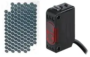
BJ100-DDT-P
PHOTOELECTRIC SENSOR, 0-100mm, PNP OPEN COLLECTOR
⚠️ Reference pricing provided. In case of supply shortages, we will connect you with our trusted procurement partners to ensure your project's continuity.
- Manufacturer: AUTONICS
- Product type: Optical / Slot Photoelectric Sensors
- Product Range: BJ Series
- Sensor Output: PNP
- Output Current: 100mA
- Sensing Range Max: 100mm
- Supply Voltage DC Max: 24V
- Supply Voltage DC Min: 12V
| Delivery and price | |
|---|---|
| Units per pack | 1 |
| Price | 66.62 € |
| Current stock | 10+ |
| Lead time | 30 days |
Datasheet

**BJ Series**

## **Compact and Long sensing distance Features**

## **Long distance sensing type**

- Long sensing distance with high quality lens

- Long sensing distance : Through-beam type 15m, Diffuse reflective type 1m, Polarized retroreflective type 3m(MS-2A)

- M.S.R.(Mirror Surface Rejection) function

- (Polarized retroreflective type)

- Compact size: W20×H32×L10.6mm

- Protection structure IP65/IP67(IEC standard)

- Light ON/Dark ON selectable by VR

- Sensitivity adjustment VR incorporated

**==> picture [27 x 8] intentionally omitted <==**

**----- Start of picture text -----**<br>
(MS-2A)<br>**----- End of picture text -----**<br>


- Built-in reverse power polarity, output short, overcurrent protection circuit

- Mutual interference prevention function (Except through-beam type)

**==> picture [53 x 8] intentionally omitted <==**

**----- Start of picture text -----**<br>
Connector type<br>**----- End of picture text -----**<br>


- Improved noise resistance and minimize effect of disturbance light

## **Please read “Caution for your safety” in operation manual before using.**

## **Specifications**

※The model name with ‘-C’ is connector type.

|Type<br>~~—__|}~~|Type<br>~~—__|}~~|Type<br>~~—__|}~~|Type<br>~~—__|}~~|Longdistance sensingtype<br>~~|}+--++--++}~~<br>|~~—~~|Longdistance sensingtype<br>~~|}+--++--++}~~<br>|~~—~~|Longdistance sensingtype<br>~~|}+--++--++}~~<br>|~~—~~|Longdistance sensingtype<br>~~|}+--++--++}~~<br>|~~—~~|Longdistance sensingtype<br>~~|}+--++--++}~~<br>|~~—~~|Longdistance sensingtype<br>~~|}+--++--++}~~<br>|~~—~~|Longdistance sensingtype<br>~~|}+--++--++}~~<br>|~~—~~|Longdistance sensingtype<br>~~|}+--++--++}~~<br>|~~—~~|
|---|---|---|---|---|---|---|---|---|---|---|---|
|Model<br>~~—__~~<br>~~es~~|NPN open<br>collector output<br>~~—__|}~~|||**BJ15M-TDT**<br>**BJ15M-TDT-C**<br>~~|}+--+~~||**BJ10M-TDT**<br>**BJ10M-TDT-C**<br>~~+--+~~|**BJ7M-TDT**<br>~~+--++--+~~|**BJ3M-PDT**<br>**BJ3M-PDT-C**<br>~~+--+~~|**BJ1M-DDT**<br>**BJ1M-DDT-C**<br>~~+}~~|**BJ300-DDT**<br>**BJ300-DDT-C**<br>~~+}~~|**BJ100-DDT**<br>**BJ100-DDT-C**<br>|~~—~~|
||PNP open<br>collector output<br>~~—__|}~~<br>~~es~~|||**BJ15M-TDT-P**<br>**BJ15M-TDT-C-P**<br>~~|}+--+~~<br>~~ee~~||**BJ15M-TDT-C-P**<br>**BJ10M-TDT-P**<br>**BJ10M-TDT-C-P**<br>~~+--+~~<br>~~ee~~|**BJ10M-TDT-C-PBJ7M-TDT-P BJ3M-PDT-P**<br>~~+--++--+~~<br>~~ee~~|**BJ7M-TDT-P BJ3M-PDT-P**<br>**BJ3M-PDT-C-P**<br>~~+--+~~|**BJ1M-DDT-P**<br>**BJ1M-DDT-C-P**<br>~~+}~~|**BJ300-DDT-P**<br>**BJ300-DDT-C-P**<br>~~+}~~|**BJ100-DDT-P**<br>**BJ100-DDT-C-P**<br>|~~—~~|
|Sensing type<br>~~—__ |}~~<br>~~es~~<br>~~ee~~||||Through-beam<br>~~|} +--+ +--+~~<br>~~ee~~<br>~~eeeeee~~||||Polarized<br>retroreflective<br>~~+--+ ~~<br>~~ee~~|Diffuse reflective<br> ~~+}~~<br>| ~~—~~<br>~~ee~~<br>~~ee~~|||
|Sensing distance<br>~~es~~<br>~~ee~~<br>~~a~~||||15m<br>~~ee~~<br>~~ee~~<br>~~a~~||10m<br>~~ee~~<br>~~ee~~<br>~~a~~|7m<br>~~ee~~<br>~~ee~~|0.1 to 3m<br>※**1**<br>(MS-2A)<br>~~ee~~|1m<br>(Non-glossy white<br>paper 300×300mm)<br>~~ee~~|300mm<br>(Non-glossy white<br>paper 100×100mm)<br>~~ee~~|100mm<br>(Non-glossy white<br>paper 100×100mm)<br>~~ee~~|
|Sensing target<br>~~ee ~~<br>~~a~~||||Opaque material over ø12mm<br> ~~ee ee ~~<br>~~a~~|||Opaque material<br>over ø8mm<br> ~~ee ~~|Opaque material<br>over ø75mm<br> ~~ee ~~|Translucent, opaque materials<br> ~~ee~~<br>~~ee~~|||
|Hysteresis<br>~~a~~||||~~-~~<br>~~a~~|||||Max. 20% at sensingdistance|||
|Response time<br>~~a ~~||||Max. 1ms<br> ~~a~~||||||||
|Power supply<br>~~ee a~~||||12-24VDC±10%(Ripple P-P: Max.10%)<br>~~a~~||||||||
|Current consumption<br>~~ee a~~||||Emitter/Receiver: Max. 20mA<br>~~a~~||||Max. 30mA||||
|Light source<br>~~ee a~~||||Infrared LED<br>(850nm)<br>~~a~~||Red LED<br>(660nm)|Red LED<br>(650nm)|Red LED<br>(660nm)|Infrared LED<br>(850nm)|Red LED<br>(660nm)|Infrared LED<br>(850nm)|
|Sensitivityadjustment<br>~~ee a~~||||Built-in the adjustment VR<br>~~a~~||||||||
|Operation mode<br>~~ee a~~<br>~~a~~||||Light on/Dark on selectable byVR<br>~~a~~||||||||
|Control output<br>~~a~~||||NPN or PNP open collector output<br>●Load voltage: Max. 26.4VDC ●Load current: Max. 100mA  ●Residual voltage - NPN: Max. 1V,PNP: Max. 2.5V||||||||
|Protection circuit<br>~~a~~||||Reversepolarity protection,output short-circuitprotection,interferenceprevention function(Except through-beam type)||||||||
|Indicator||||Operation: Red,Stable: Green(Emitter’spower indicator: Green)||||||||
|Insulation resistance||||Max.20MΩ(at 500VDC megger)||||||||
|Noise resistance||||±240V the square wave noise(pulse width:1㎲)bythe noise simulator||||||||
|Dielectric strength||||1000VAC 50/60Hz for 1minute||||||||
|Vibration||||1.5mm amplitude or 300m/s<br>2at frequencyof 10 to 55Hz(for 1 min.)in each of X,Y,Z directions for 2 hours||||||||
|Shock||||500m/s<br>2(approx. 50G)in each of X,Y,Z directions for 3 times||||||||
|Environ-<br>ment<br>~~—————~~||Ambient illumination<br>~~—————~~||Sunlight: Max. 11,000lx,Incandescent lamp: Max. 3,000lx(Receiver illumination)<br>~~—————~~||||||||
|||Ambient temperature <br>~~—————~~||-25 to 55℃,storage: -40 to 70℃<br>~~—————~~||||||||
|||Ambient humidity<br>~~—————~~||35 to 85%RH,storage: 35 to 85%RH<br>~~—————~~||||||||
|Protection<br>~~ao~~||||BJ - IP65(IEC standard),BJ-C - IP67(at non-dew status)<br>~~ao~~||||||||
|Material<br>~~ao~~||||Case: PC+ABS,LED Cap: PC,Sensing part: PMMA<br>~~ao~~||||||||
|Cable<br>※**2**<br>~~ao~~<br>~~————————————~~||||BJ: ø3.5, 3-wire, Length: 2m(Emitter of through-beam type: ø3.5, 2-wire, Length: 2m)<br>(AWG24,Core diameter: 0.08mm,Number of cores: 40,Insulator out diameter: ø1)<br>~~ao~~<br>~~————————————~~||||||||
|Accessory <br>~~————————————~~|||Common<br>~~————————————~~|Mountingbracket,Bolt,Nut,VR adjustment driver<br>~~————————————~~||||||||
||||<br>Individual <br>~~————————————~~|~~-~~<br>~~————————————~~||||Reflector(MS-2A) <br>~~————————————~~|~~-~~|||
|Approval<br>~~————————————~~||||~~————————————~~|~~————————————~~|||||||
|Unit weight<br>~~————————————~~<br>~~a ~~||||BJ: Approx. 90g, BJ-C: Approx. 20g<br>~~————————————~~<br> ~~eG~~||||BJ: Approx 60g<br>BJ-C: Approx 30g <br>~~————————————~~<br>~~eG~~|BJ: Approx. 45g, BJ-C: Approx. 10g<br>~~eG~~|||


※The temperature or humidity mentioned in Environment indicates a non freezing or condensation environment.

A-12

~~eC~~ **Long sensing distance/BGS reflective/Micro spot type**

**(A) Photo electric sensor (B) Fiber Fiber opticsensor sensor (C) Door/Area Door/Area sensor (D) Proximity Proximity sensor (E) Pressuresensor Pressuresensor sensor (F) Rotary encoder**

**(G) Connector/ Socket (H) Temp. controller**

**(I) SSR/ Power controller (J) Counter (K) Timer (L) Panel meter**

**(M) Tacho/ Speed/ Pulse meter (N) Display unit**

**(O) Sensor controller (P) Switching mode power supply (Q) Stepper motor& Driver&Controller (R) Graphic/ Logic panel (S) Field network device (T) Software (U) Other**

- **(A) Photo**

- **Transparent glass sensing/BGS reflective/Micro spot type electric** ~~:~~ **Features sensor** ~~7~~ **BGS reflective type (B) Fiber** ●  Adopts BGS method superior than convergent reflective    to minimize error by background, or color, material of **opticsensor** sensing object for stable sensing by adjusting the volume **(C) Door/Area** ● Visible light source to check the position of sensing spot and small spot i **sensor** minimizing effect of the ambient objects with narrow sensing width **Transparent glass Transparent glass sensing type / Micro spot type sensing type (D) Proximity**

- ● Stable sensing for transparent object(LCD, PDP, glass etc) **sensor** by BJG30-DDT **BGS reflective** |_| ● Easy to check sensing location with visible micro spot(BJN Series)  ● Detects tiny objects (min. sensing target Ø0.2mm copper wire) (Spot size) =*<t*<t **type (E) Pressuresensor** 2 **Commonness** Ø5.0/4.5/6.5mm

**Transparent glass sensing type BGS reflective type** =*<t*<t (Spot size) Ø5.0/4.5/6.5mm **Micro spot type** tb (Spot size) ※Spot is visible with bare eyes Ø2.0/2.5mm while beam(line) is not.

- Compact size: W20×H32×L10.6mm

- Protection structure IP65(IEC standard)

- Light ON/Dark ON selectable by VR(Except BJG30-DDT)

- Sensitivity adjustment VR incorporated(Except BJG3 DDT)

- Built-in reverse power polarity, output short, overcurrent protection circuit

- Mutual interference prevention function(Except BGS reflective type)

**Micro spot type**

- Improved noise resistance and minimized effect of disturbance light

**Please read “Caution for your safety” in operation manual before using.**

## **Specifications**

|Type<br>~~Re~~<br>~~gg~~|Type<br>~~Re~~<br>~~gg~~|Type<br>~~Re~~<br>~~gg~~|Transparentglass sensingtype <br>~~GO~~<br>~~gg~~|Transparentglass sensingtype <br>~~GO~~<br>~~gg~~|Transparentglass sensingtype <br>~~GO~~<br>~~gg~~|BGS reflective type<br>~~GO~~<br>~~gg~~|BGS reflective type<br>~~GO~~<br>~~gg~~|BGS reflective type<br>~~GO~~<br>~~gg~~|Micro spot type<br>~~GO~~<br>~~gg~~<br>~~ee~~|Micro spot type<br>~~GO~~<br>~~gg~~<br>~~ee~~|
|---|---|---|---|---|---|---|---|---|---|---|
|Model<br>~~Re~~<br>~~gg~~<br>~~Re~~|NPN open collector output <br>~~Re~~<br>~~gg~~<br>~~Re~~||**BJG30-DDT**<br>~~GO~~<br>~~gg~~<br>|||**BJ30-BDT**<br>~~GO~~<br>~~gg~~<br>|**BJ50-BDT**<br>~~GO~~<br>~~gg~~<br>|**BJ100-BDT**<br>~~GO~~<br>~~gg~~<br>~~CO~~<br>|**BJN50-NDT**<br>~~GO~~<br>~~gg~~<br>~~CO~~<br>|**BJN100-NDT**<br>~~GO~~<br>~~ee~~<br>|
||PNP open collector output <br>~~gg~~<br>~~GQ~~<br>~~Re~~||~~-~~<br>~~gg~~<br>~~GQ~~<br>|||**BJ30-BDT-P**<br>~~gg~~<br>~~GQ~~<br>|**BJ50-BDT-P**<br>~~gg~~<br>~~GQ~~<br>|**BJ100-BDT-P BJN50-NDT-P BJN100-NDT-P**<br>~~gg~~<br>~~GQ~~<br>~~CO~~<br>|**BJ100-BDT-P BJN50-NDT-P BJN100-NDT-P**<br>~~gg~~<br>~~GQ~~<br>~~CO~~<br>|**BJ100-BDT-P BJN50-NDT-P BJN100-NDT-P**<br>~~ee~~<br>~~GQ~~<br>|
|Sensingtype<br>~~gg~~<br>~~Re~~|||Diffuse reflective<br>~~gg~~<br>~~QO~~|||BGS reflective<br>~~gg~~<br>~~CO~~<br>~~QO~~|||Narrow beam reflective<br>~~gg~~<br>~~ee~~<br>~~CO~~<br>~~QO~~||
|Sensing distance<br>~~Re~~<br>~~re es~~|||30mm<br>(Non-glossy<br>white paper<br>100×100mm)<br>~~QO~~<br>~~es~~||15mm<br>(Transparent<br>glass 50×50mm,<br>t=3.0mm)<br>~~QO~~<br>~~es~~|10 to 30mm<br>(Non-glossy<br>white paper<br>50×50mm)<br>~~QO~~|10 to 50mm<br>(Non-glossy<br>white paper<br>50×50mm)<br>~~QO~~|10 to 100mm<br>(Non-glossy<br>white paper<br>100×100mm)<br>~~CO~~<br>~~QO~~|30 to 70mm<br>~~CO~~<br>~~QO~~|70 to 130mm<br>~~QO~~|
|Sensing target<br>~~re es~~<br>~~ee es~~|||Transparent glass,<br>opaque materials,translucent<br>~~es~~<br>~~es ee~~|||Translucent, opaque materials<br>~~ee~~~~**s** esee~~|||Translucent, opaque materials<br>~~es~~||
|Min.diameter of<br>transmittingSPOT<br>~~re es~~<br>~~ee es~~|||~~-~~<br>~~es~~<br>~~es ee~~|||Approx.<br>ø5.0mm<br>~~ee~~~~**s** es~~|Approx.<br>ø4.5mm<br>~~es~~|Approx.<br>ø6.5mm<br>~~ee~~|Approx.<br>ø2.0mm<br>~~es~~|Approx.<br>ø2.5mm|
|Min.sensingtarget<br>~~ee es~~<br>~~R~~<br>~~ee es~~|||~~-~~<br>~~es ee~~~~**s** es ee~~<br>~~R~~<br>~~esee~~||||||Approx. min. ø0.2mm(Copper wire)<br>~~es~~||
|Hysteresis<br>~~R~~<br>~~ee es~~<br>~~Re~~|||Max. 20% at sensing distance<br>~~R~~<br>~~es~~<br>~~GO~~|||Max. 10% at sensing distance<br>~~R~~<br>~~ee~~<br>~~GO~~|||Max. 25% at<br>sensingdistance<br>~~GO~~|Max. 20% at<br>sensingdistance<br>~~GO~~|
|Response time<br>~~ee es~~<br>~~Re~~<br>~~a~~|||Max. 1ms<br>~~es~~<br>~~GO~~|||Max. 1.5ms<br>~~ee~~<br>~~GO~~|||Max. 1ms<br>~~GO~~||
|Power supply<br>~~Re~~<br>~~a~~<br>~~RR~~|||12-24VDC ±10%(Ripple P-P: Max.10%)<br>~~GO~~||||||||
|Current consumption<br>~~a~~<br>~~RR~~<br>~~Re~~|||Max. 30mA<br>~~GO~~||||||||
|Light source/Wavelength<br>~~RR~~<br>~~Re~~<br>~~Re~~|||Infrared LED(850nm)<br>~~GO~~|||Red LED(660nm)<br>~~GO~~|||Red LED(650nm)<br>~~GO~~||
|Sensitivityadjustment<br>~~Re~~<br>~~Re~~<br>~~RR~~|||~~-~~<br>~~GO~~|||Built-in the adjustment VR<br>~~GO~~|||||
|Operation mode<br>~~Re~~<br>~~RR~~|||Light ON fixed|||Light ON / Dark ON selectable byVR|||||
|Control output<br>~~RR~~<br>~~Re~~|||NPN open collector output<br>●Load voltage: Max. 26.4VDC<br>●Load current: Max.100mA<br>●Residual voltage: Max. 1V|||NPN or PNP open collector output<br>●Load voltage: Max. 26.4VDC    ●Load current: Max. 100mA<br>●Residual voltage - NPN: Max. 1V, PNP: Min. 2.5V|||||
|Protection circuit<br>~~Re~~<br>~~Re~~|||Reversepolarity protection,output short-circuitprotection,interferenceprevention function(Exept BGS reflective type)||||||||
|Indicator<br>~~Re~~<br>~~Re~~<br>~~RR~~|||Operation indicator: red,Stabilityindicator:green||||||||
|Insulation resistance<br>~~Re~~<br>~~RR~~<br>~~a~~|||Min. 20MΩ(at 500VDC megger)||||||||
|Noise resistance<br>~~RR~~<br>~~a~~<br>~~Rn~~|||±240V the square wave noise(pulse width:1㎲)bythe noise simulator||||||||
|Dielectric strength<br>~~a~~<br>~~Rn~~<br>~~Re~~|||1,000VAC 50/60Hz for 1minute||||||||
|Vibration<br>~~Rn~~<br>~~Re~~<br>~~Re~~|||1.5mm amplitude or 300m/s<br>2at frequencyof 10 to 55Hz(for 1 min.)in each of X,Y,Z directions for 2 hours||||||||
|Shock<br>~~Re~~<br>~~Re~~|||500m/s<br>2(approx. 50G)in each of X,Y,Z directions for 3 times||||||||
|Environ-<br>ment<br>~~Re~~<br>~~SSSSSSSSSSSS—~~||Ambient illumination<br>~~Re~~<br>~~SSSSSSSSSSSS—~~<br>~~Rs~~|Sunlight: Max. 11,000lx,Incandescent lamp: Max. 3,000lx(Receiver illumination)<br>~~SSSSSSSSSSSS—~~||||||||
|||Ambient temperature <br>~~SSSSSSSSSSSS—~~<br>~~Rs~~<br>~~Rs~~|-25 to 55℃,storage:-40 to 70℃<br>~~SSSSSSSSSSSS—~~||||||||
|||Ambient humidity<br>~~SSSSSSSSSSSS—~~<br>~~Rs~~<br>~~Rs~~|35 to 85%RH,storage: 35 to 85%RH<br>~~SSSSSSSSSSSS—~~||||||||
|Protection<br>~~Rs~~<br>~~a~~|||IP65(IEC standard)||||||||
|Material<br>~~a~~<br>~~Re~~|||Case: PC+ABS,LED Cap: PC,Sensing part: PMMA||||||||
|Cable<br>~~Re~~|||ø3.5,3-wire,Length: 2m(AWG24,Core diameter: 0.08mm,Number of cores: 40,Insulator out diameter: ø1)||||||||
|Accessory<br>~~Re~~<br>~~Rf~~<br>~~Re~~|||Mountingbracket,Bolt<br>~~Rf~~|||Mountingbracket,Bolt,Adjustment driver<br>~~Rf~~|||||
|Approval<br>~~Re~~<br>~~RR~~|||~~GO~~|~~GO~~|||||||
|Unit weight<br>~~Re~~<br>~~RR~~|||Approx. 45g<br>~~GO~~|||Approx. 50g<br>~~GO~~|||Approx. 45g<br>~~GO~~||


A-13

**BJ Series**

## **Feature data**

## **Through-beam type**

## **● BJ15M-TDT-(C)-(P) / BJ10M-TDT-(C)-(P) / BJ7M-TDT-(P)**

**==> picture [442 x 587] intentionally omitted <==**

**----- Start of picture text -----**<br>
Parallel shifting characterisitic Angle characteristic<br>Measuring method Data Measuring method Data<br>24<br>20<br>BJ15M-TDT-(C)-(P)<br>20 BJ10M-TDT-(C)-(P) BJ15M-TDT-(C)-(P)<br>BJ7M-TDT(-P) 16<br>Emitter 16 BJ10M-TDT-(C)-(P)<br>12<br>L ℓ1 12 L θ Emitter 8 BJ7M-TDT(P)<br>8<br>4<br>Receiver<br>4<br>Receiver<br>0<br>0 30°   20°   10°     0°   10°   20°   30°<br>80  40  0  40  80 Left Cent er Right<br>ℓ1 ℓ1 Operation angle(θ)<br>Sensing area(cm)<br> Retroreflective type<br>● BJ3M-PDT-(C)-(P)<br>Parallel shifting characterisitic Sensor angle characteristic Reflector angle characteristic<br>Measuring method Data Measuring method Data Measuring method Data<br>6.0<br>5.0 5.0 4.5<br>Reflector 4.0 Reflector 4.0 Reflector 3.5<br>MS-2A<br>ℓ1 3.0 θ L 3.0 L 2.5<br>2.0 2.0 θ 1.5<br>1.0 1.0 0.5<br>0 0.0 0.0<br>160 80  0  80 160 10°     5°      0°      5°    10° 40°   20°     0°     20°   40°<br>ℓ1 ℓ1 Left Cen te r Ri ght Left Cen te r Ri ght<br>Sensing area (mm) Operation angle(θ) Operation angle(θ)<br> Diffuse/Narrow beam reflective type<br>●  BJ1M-DDT-(C)-(P) ● BJ300-DDT-(C)-(P)  ●  BJ100-DDT-(C)-(P)<br>Sensing area characteristic Sensing area characteristic Sensing area characteristic<br>Measuring method Data Measuring method Data Measuring method Data<br>2000 1000 200<br>1600 160<br>Standard  Standard  800 Standard<br>ℓ1 sensing  1200 ℓ1 sensing  ℓ1 sensing  120<br>target target 600 target<br>800 80<br>400<br>L 400 L L 40<br>200<br>200 20<br>0<br>0 20  10  0  10  20 0<br>40  20  ℓ1 0  ℓ1 20  40 ℓ1 ℓ1 40  20 ℓ1 0  ℓ1 20  40<br>Sensing area(mm) Sensing area(mm) Sensing area(mm)<br> ●  BJG30-DDT  ●  BJN50-NDT-(P)   ● BJN100-NDT-(P)<br>Sensing area characteristic Sensing area characteristic Sensing area characteristic<br>Measuring method Data Measuring method Data Measuring method Data<br>30 120 180<br>160<br>25 100 140<br>ℓ1 Standard sensing  20 ℓ1 Standard sensing  80 ℓ1 Standard sensing  120<br>target target target 100<br>15 60 80<br>L 10 L 40 L 60<br>40<br>5 20<br>20<br>0 0 0<br>20 15 10  5   0   5  10 15 20ℓ1 ℓ1 2  1  ℓ10 ℓ1 1  2 2  1  ℓ1 0  ℓ1 1  2<br>Sensing area(mm) Sensing area (mm) Sensing area (mm)<br>Sensing distance L(m) Sensing distance L(m)<br>Sensing distance L(m) Sensing distance L(m) Sensing distance L(m)<br>Sensing distance L(mm) Sensing distance L(mm) Sensing distance L(mm)<br>Sensing distance L(mm) Sensing distance L(mm)<br>Sensing distance L(mm)<br>**----- End of picture text -----**<br>


A-14

## **Long sensing distance/BGS reflective/Micro spot type**

## **Feature data**

**==> picture [483 x 571] intentionally omitted <==**

**----- Start of picture text -----**<br>
 Feature data<br>(A)<br>Photo<br> BGS reflective type electric<br>●  BJ30-BDT / BJ30-BDT-P  ● BJ50-BDT / BJ50-BDT-P   ● BJ100-BDT / BJ100-BDT-P sensor<br>(B)<br>Sensing area characteristic Sensing area characteristic Sensing area characteristic Fiber<br>optic<br>Measuring method Data Measuring method Data Measuring method Data sensor<br>35 60 110<br>30 5550 10090 (C) Door/Areasensor<br>Standard  25 Standard  45 Standard  80<br>ℓ1 sensing  ℓ1 sensing  40 ℓ1 sensing  70 (D)<br>target 20 target 3530 target 60 Proximitysensor<br>L 1510 L 252015 L 504030 (E) Pressure<br>5 10 20 sensor<br>5 10<br>0 0 0 (F)<br>2.0    1.0     0     -1.0   -2.01.5      0.5   -0.5    -1.5 3    2    1     0   -1   -2   -3 4   3   2  1   0  -1 -2  -3  -4 Rotaryencoder<br>ℓ1 ℓ1 ℓ1 ℓ1 ℓ1 ℓ1<br>Sensing area(mm) Sensing area(mm) Sensing area(mm) (G) Connector/<br>Socket<br>Sensing distance by material Sensing distance by material Sensing distance by material<br>40 60 120 (H)<br>Temp.<br>50 100 controller<br>30<br>40 80<br>(I)<br>20 30 60 SSR/Power<br>controller<br>20 40<br>10<br>10 20 (J)<br>Counter<br>0 0 0<br>White Corrugated Black Rubber SUS PCB Acryl White Corrugated Black Rubber SUS PCB Acryl White Corrugated Black Rubber SUS PCB Acryl<br>paper cardboard paper (black) (green) (transparent) paper cardboard paper (black) (green) (transparent) paper cardboard paper (black) (green) (transparent)<br>Sensing target(material) Sensing target(material) Sensing target(material) (K) Timer<br>Sensing distance by color Sensing distance by color Sensing distance by color<br>40 60 120 (L)<br>Panel<br>50 100 meter<br>30<br>40 80 (M)<br>Tacho/<br>20 30 60 Speed/ Pulse<br>meter<br>20 40<br>10 (N)<br>10 20 Display<br>unit<br>0 0 0<br>White Red OrangeYellowGreen Blue Navy Violet Black White Red OrangeYellowGreen Blue Navy Violet Black White Red OrangeYellowGreen Blue Navy Violet Black<br>Sensing target(colored paper) Sensing target(colored paper) Sensing target(colored paper) (O)Sensor<br>controller<br> Connections (P)Switching<br>mode power<br>● Through-beam type       ● Retroreflective type ●  Diffuse/Narrow beam/ supply<br>   BGS reflective  type (Q)<br>Stepper<br>motor&<br>Driver&Controller<br>Brown Brown Brown (R)<br>+- BrownBlue Sensing target BlackBlue ※※ 12 LoadLoad +- Reflector BlackBlue ※※ 12 LoadLoad +- Sensing target BlackBlue ※※ 12 LoadLoad +- Graphic/Logicpanel(S)Field<br>Sensing  network<br>※1: The load connection of NPN open collector output target device<br>※2: The load connection of PNP open collector output<br>(T)<br>Software<br> Connections for connector part<br>●  Connector cable(sold separately) (U)<br>Connector pin No. Cable colors  Function Other<br>Sensing distance L(mm)<br>Sensing distance L(mm) Sensing distance L(mm)<br>Sensing distance L(mm) Sensing distance L(mm) Sensing distance L(mm)<br>Sensing distance L(mm) Sensing distance L(mm) Sensing distance L(mm)<br>**----- End of picture text -----**<br>


||||||**py**|
|---|---|---|---|---|---|
||①②|Connector pin No. Cable colors<br>①<br>Brown|Function<br>Power Source(+V)|※Connector cable model<br>: CID408-<br> , CLD408-||
||③④|②<br>White<br>③<br>Blue|~~-~~<br>Power Source(0V)|※Please refer to G-6 for connector cable.||
|||④<br>Black|Output|||
|M8|Connector pin|※Connector pin ② is N.C(Not Connected) terminal.||||


A-15

**BJ Series**

## **Control output diagram**

**==> picture [437 x 173] intentionally omitted <==**

**----- Start of picture text -----**<br>
● NPN open collector output     ● PNP open collector output<br>Photoelectric sensor circuit Connection Photoelectric sensor circuit Connection<br>(Brown)+V (Brown)+V<br>Load<br>(Black)output currentOver  Max.100mA<br>+ 12-24VDC protection + 12-24VDC<br>currentOver  Max.100mA - ±10% (Black)output - ±10%<br>protection (Blue)0V (Blue)0V Load<br> Operation mode<br>Operation mode Light ON Dark ON<br>Received light Received light<br>Receiver operation<br>Interrupted light Interrupted light<br>Operation indicator ON ON<br>(red LED) OFF OFF<br>ON ON<br>Transistor output<br>OFF OFF<br>Main circuit Main circuit<br>**----- End of picture text -----**<br>


## **Dimensions**

(unit: mm)

**==> picture [440 x 417] intentionally omitted <==**

**----- Start of picture text -----**<br>
●Through-beam type ●Through-beam type(Connector type)<br>Power indicator(green) Operationindicator(red) 10.6 Stabilityindicator(green) 2.720 Power indicator(green) Operationindicator(red) 10.6 Stabilityindicator(green) 3 20<br>M8 M8<br>Cable: ø3.5, 2m<br><Emitter> <Receiver> <Emitter> <Receiver><br>● Retroreflective type ● Retroreflective type(Connector type)<br>Operationindicator(red) 10.6 Stabilityindicator(green) 2.720 Operation indicator(red) 10.6 Stability indicator(green) 3 20<br>Optical axis of receiver<br>Optical axis of emitter<br>Cable: ø3.5, 2m M8<br>● Diffuse/Narrow beam/BGS reflective type ● Diffuse reflective type(Connector type)<br>   - Connect the bracket A 22     - Connect the bracket B<br>M3 Bolt 10.5 Operation indicator Stability indicator 20<br>(red) (green) 3<br>Optical axis<br>of receiver<br>Optical axis<br>of emitter<br>Stability indicator(green)<br>20<br>Operation indicator(red) Optical axis 2.7<br>of receiver M3Bolt M8<br>Optical axis<br>of emitter 24.6 29.5<br>M3 Bolt Cable: ø3.5, 2m<br>32 25 32 25<br>15 15<br>2.7 3<br>8 32 25 8 32 25<br>15 15<br>2.7 3<br>24.6 13.3<br>35 18 32 25 35<br>16.7<br>8.5<br>3<br>42.5 8 15 32 25<br>2.7<br>**----- End of picture text -----**<br>


A-16

**Long sensing distance/BGS reflective/Micro spot type**

**(A) Photo electric sensor (B) Fiber optic sensor (C) Door/Area sensor (D) Proximity sensor (E) Pressure sensor (F) Rotary encoder (G) Connector/ Socket (H) Temp. controller (I) SSR/Powercontroller Powercontroller controller**

**(O) Sensor controller (P) Switching mode power supply (Q) Stepper Optical axis adjustment motor&Driver&Controller ●Through-beam type (R) Graphic/** 1. Place the emitter and the Receiver **Logicpanel** receiver facing each other and Adjust supply the power. Emitter Right/Left **(S)Fieldnetwork** 2. After adjusting the position of **device** the emitter and the receiver and check their stable **(T)** Adjust Up/Down **Software** indicating range, mount them in the middle of the range. **(U)** 3. After mounting this unit, check the operation of the sensor **Other** and lighting of the stability indicator in both status. (None or sensing target status)

**==> picture [433 x 174] intentionally omitted <==**

**----- Start of picture text -----**<br>
● Reflector ● Bracket A ● Bracket B (sold separately)<br>  (accessory: MS-2A,<br>    sold separately: MS-2S, MS-3S) 10.5<br>M3 Bolt 3<br>36 14<br>M3 Bolt 22 26.5 ø3.4 8<br>34 2-ø3.8 2.5<br>40.5 8.5<br>10° 20°<br>R25 R25<br>3 1.2<br>14 8<br>52 60.5<br>42.5 25 35 18 6<br>1.2 12.5<br>**----- End of picture text -----**<br>


## **Operation timing diagram**

## **● Retroreflective/Diffuse/Narrow beam/ BGS reflective type**

## **● Through-beam type**

**==> picture [486 x 164] intentionally omitted <==**

**----- Start of picture text -----**<br>
(I)<br>light ON areaStable High light ON areaStable High SSR/Powercontroller<br>Unstable<br>Unstable Incident Operation lev el  light ON area Incident (J) Counter<br>operation area levellight light OFF areaUnstable levellight Operationlevel (K)<br>Timer<br>Stable  Stable<br>light OFF area light OFF area (L)<br>Low Low Panel<br>Stability meter<br>Stabilityindicator(green LED) OFFON indicator(green LED) OFFON (M)Tacho/<br>operationLight ON TransistoroutputOperationindicator(red LED) OFFOFFONON operationLight ON Operationindicator(red LED)Transistoroutput OFFOFFONON Speed/ Pulsemeter (N)Displayunit<br>**----- End of picture text -----**<br>


- ※The waveforms of “Operation indicator” and “Transistor output” are for Light ON operation. They are opposite operation for Dark ON operation.

## **Mounting and sensitivity adjustment**

## **For mounting**

Please use bolts M3 for M3×18mm mounting of sensor, set the tightening torque under 0.5N[.] m.

## **●Through-beam type**

## **Switching of operation mode**

|Light ON<br>operation|D<br>L|Turn the switching volume of operation<br>mode to end of right(L direction), it is<br>set as Light ON.|
|---|---|---|
|Dark ON<br>operation|D<br>L|Turn the switching volume of operation<br>mode to end of left(D direction), it is set<br>as Dark ON.|


- ※For through-beam type, the switching volume of operation mode is built-in the receiver.

- ※When the sensing target is translucent or small(under sensing target of ‘ **Specifications** ’), it may not be detected by the sensor because the light can penetrate it.

A-17

## **BJ Series**

## **● Retroreflective type**

- 1.Place the sensor and the reflector facing each other and supply the Adjust Right/Left

- power.

- 2.After adjusting the position of the sensor and reflector and check their stable indicating range, Reflector mount them in the middle of the range. (None or sensing target Adjust Up/Down status)

- 3.After mounting this unit, check the operation of the sensor and in both status. (None or sensing target status)

## **● Diffuse/Narrow beam/BGS reflective type**

After place a sensing target, adjust the sensor to up or down, right or left.

Then, fix the sensor in the center of position where the stability is Sensing target operating.

## **● Object(Copper wire) detection <Micro spot type>**

**==> picture [213 x 84] intentionally omitted <==**

**----- Start of picture text -----**<br>
[Figure 1] [Figure 2]<br>When copper<br>wire is moved. Approx. 0 to 15°<br>Copper<br>wire Copper<br>wire<br>**----- End of picture text -----**<br>


- ※Mount the sensor slanted at an angle ranged 0 to 15˚ shown above as [Figure 2] for stable detection to detect as shown in [Figure 1].

## **Sensitivity adjustment**

|Order|Position|Description|
|---|---|---|
|1|MIN. MAX.<br>(A)|Turn the adjustment VR to the right of<br>min. and check position(A) where the<br>operation indicator is turned ON in “Light<br>ON status”.|
|2|MIN. MAX.<br>(A)<br>(C)<br>(B)|Turn the adjustment VR more to the right<br>of position(A), check position(B) where<br>the operation indicator is turned ON. And<br>turn the adjustment VR to the left, check<br>position(C) where the operation indicator is<br>turned OFF in “Light OFF status”.<br>※If the operation indicator is not turned ON<br>although the adjustment VR is turned to<br>the max. position, the max. position is (C).|
|3|MIN. MAX.<br>Optimal<br>sensitivity<br>(A)<br>(C)|Set the adjustment VR at the center of (A)<br>and (C). To set the optimum sensitivity,<br>check the operation and lighting of<br>stability indicator with sensing target or<br>without it. If the stability indicator is not<br>turned ON, please check the sensing<br>method again because sensitivity is<br>unstable.|


- ※No sensitivity adjustment function available for BJG30DDT models.

||Light ON status|L|ight OFF status|
|---|---|---|---|
|Through-<br>beam<br>type<br>Em|itter<br>Receiver|Emitt|er<br>Sensing<br>target<br>Receiver|
|Retro-<br>refective<br>type<br>Rec|Refector<br>eiver|Senso|Sensing<br>target<br>Background<br>object<br>r|
|Diffuse/<br>Narrow<br>beam/<br>BGS<br>refective<br>Senso|Background<br>object<br>r<br>Sensing<br>target||Background<br>object|


- ※Set the sensitivity to operate in stable light ON area and the reliability for the environment (temperature, voltage, dust etc) is increased. In unstable light ON area,  be sure that the variation of environment.

- ※Do not apply excessive force on the adjustment VR, it may be broken.

A-18
Updated at February 9, 2023
About Novapart
Novapart is a B2B electronic component broker specialising in stock shortages and cost reduction. We source hard-to-find parts and identify compliant alternatives across a catalogue of 410,000+ components from 500+ manufacturers.
Learn more →Stock Shortage Specialist
When a component is unavailable, discontinued or has an unacceptable lead time, we tap into our network of vetted European and Asian distributors to source what you need — without compromising on quality or traceability.
Request a quote →Compliant Alternatives
We identify pin-to-pin, electrically equivalent substitutes that meet the same certifications (RoHS, AEC-Q100, REACH) as your original specification — validated against datasheets, not just part numbers. Often at a lower cost.
BOM Analysis service →