


BD35
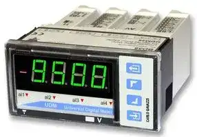
Digital Panel Meter, Modular, Multifunction, UDM35 Series, 4 Digits, Display, 3.5 Digit
- Manufacturer: CARLO GAVAZZI
- Product type: Digital Panel Meters
- No. of Digits / Alpha:3-1/2; Meter Function:Multifunction; Meter Range:-; Digit Height:14.2mm; Panel Cutout Height:45mm; Panel Cutout Width:92mm; Supply Voltage Min:-; Supply Voltage Max:-; O
- SVHC: No SVHC (21-Jan-2025)
- Meter Range: -
- Digit Height: 14.2mm
- Product Range: -
- Meter Function: Multifunction
- Panel Cutout Width: 92mm
- Supply Voltage Max: -
- Supply Voltage Min: -
- Panel Cutout Height: 45mm
- No. of Digits / Alpha: 3-1/2
- Operating Temperature Max: 50°C
- Operating Temperature Min: 0°C
| Delivery and price | |
|---|---|
| Units per pack | 1 |
| Price | 36.44 € |
| Current stock | 10+ |
| Lead time | 30 days |
## **Digital Panel Meters Modular Indicator and Controller Type UDM35**

   - **Multi-input modular instrument 3 1/2 DGT LED**

   - **0.1% RDG  basic accuracy**

   - **TRMS  AC  current and voltage measurements**

   - **AC/DC current measurements: selectable full scales (200µA to 5A)**

   - **AC/DC voltage measurements: selectable full scales (200mV to 500V)**

   - **°C or °F  temperature measurements (Pt100-250-500-1000, Ni100, TC J-K-S-T-E)**

   - **Resistance measurements: selectable full scales (20** Ω **to 20k** Ω **)**

   - **Dual rate, speed, frequency and period measurement (0.001Hz to 50kHz)**

   - **Up to 4 independent alarm set-points (optional)**

   - **20mA/10VDC  analog output (optional)**

- **Front protection degree: IP67, NEMA12, NEMA4x**

- **"Indoor use only"**

   - **Serial port RS485 or RS232 (optional)**

   - **MODBUS, JBUS communication protocol**

- **Linearization of Hz inputs up to 16 points**

## **Product Descri tion p**

µp-based digital panel by means of optional Udmmeter, 3 1/2 DGT LED indiSoft software. UDM35 cator, for current, voltage, includes storage min-max temperature, resistance, functions  and double level rate, frequency, speed and protection password. period measurements. MeaHousing for panel mounting suring ranges and  functions with front protection degree: easily programmable from IP67, NEMA12, NEMA4x the key-pad or from the PC "Indoor use only".

## **How to order**

**Model Slot A Slot B Slot C Slot D Options**

## **How to order**

## **UDM35 XXX XX XX X XX**

## **UdmSoft-kit**

**UdmSoft-kit:** software plus communication cable for programming UDM35 by means of PC.

**UdmSoft:** software for programming UDM35/40/60 by means of PC, downloadable from www.carlogavazzi.com.

## **T e Selection yp**

**Slot A (measuring inputs)**

## **Slot B (communication)**

## **Slot C (communication and alarm)**

## **Slot D (power supply)**

**LSX:** signal inputs: **XX:** None **XX:** None **H:** 90 to 260V AC/DC 0.2-2-20mA DC/AC; **SX:** Serial port RS485 **R1:** Single relay output, **L:** 18 to 60V AC/DC 0.2-2-20V DC/AC **SY:** Serial port RS232 (AC1-8AAC, 250VAC) (24 to 48V AC/DC ± **LSE/ AV(*):** Single analogue output, **R2:** Dual relay output, 25% according to UL) **LSF:** signal inputs: + AUX: 0 to 20mA DC and (AC1-8AAC, 250VAC) **3:** 10 to 28V DC 0.2-2-20mA DC/AC; 0 to 10V DC **R4:** Dual relay output, (AC1(12 to 24V DC ± 15% 0.2-2-20V DC/AC 8AAC, 250VAC) + dual according to UL) **HSX:** signal inputs: open collector output 0.2-2-5A DC/AC; (NPN, 100mA) 20-200-500V DC/AC **R5:** 4 relay outputs **TRX:** signal inputs: TC tem(AC1-5AAC, 250VAC) perature probes (J-K- **AV(*):** Single analogue output, S-T-E, Pt100-250-5000 to 20mA DC and 1000) and resistance 0 to 10V DC (0.02-0.2-2-20kΩ) **TF1:** 0.001Hz to 50kHz for **(*):** The two analogue **Options** DC signals: PNP, outputs cannot be NPN, NAMUR, TTL, used at the same **XX:** None free of voltage, contime. It is possible to **TX:** Tropicalization tacts, voltages up to plug in only one 14VDC module by instru- **TF2:** 0.001Hz to 50kHz for ment. AC signals: pick-up, voltages up to 500VAC

**1**

Specifications are subject to change without notice  UDM35 DS ENG   090112

**UDM35**

## **In ut s ecifications p p**

|**Input specifications**||
|---|---|
|**Analogue inputs**<br>Channels and variable<br>BQ LSX module<br>1, mA and V DC/AC<br>BQ LSE/LSF module<br>1, mA and V DC/AC + AUX<br>BQ HSX module<br>1,A and V DC/AC<br>BQ TRX module<br>1, temperature<br>BQ TRX module<br>1, resistance<br>BQTF1 module<br>2, frequency<br>BQTF2 module<br>2,frequency<br>**Type of input**<br>NPN (DC)<br>Signal level: ON < 2VDC,<br>OFF open collector (leak-<br>age current <=1mA).<br>PNP (DC)<br>Signal level: ON >10VDC,<br>OFF open collector (leak-<br>age current <=1mA).<br>NAMUR (DC)<br>Signal level: ON <=<br>1mADC, OFF >= 2.2<br>mADC.<br>TTL (DC)<br>Signal level: ON >4VDC,<br>OFF<=2VDC.<br>Free of voltage contact(DC)<br>Input load: ON <1kohm,<br>OFF >20kohm.<br>Voltage (AC) up to 100VAC<br>Signal level: ON > 2VAC<br>(5.65 Vpp).<br>Voltage (AC) up to 500VAC<br>Signal level: ON > 9VAC<br>(25.4 Vpp).<br>**Digital inputs**<br>Incl. in the measuring module<br>Number of inputs<br>1 (voltage-free)<br>Use<br>key-pad lock<br>Display hold<br>Reset of latch alarms<br>Contact reading signal<br>BQ xxx: <0.1mA, <3,5V DC<br>BQ LSE/BQ LSF: <2.5mA,<br><14V DC<br>BQTF1: <6mA, <7VDC<br>BQTF2: <0.25mA, <3VDC<br>Close contact resistance<br>Max 1kΩ<br>Open contact resistance<br>Min 500kΩ(BQTFx: 100kΩ)<br>Insulation<br>Non-insulated<br>**Accuracy**(display, RS485)<br>See table “Measuring<br>accuracy”, temperature drifts<br>and minimum-maximum<br>indications”<br>**Additional errors**<br>Humidity<br>0.3%RDG (BQTFx: 0.05%),<br>60%to90% R.H.<br>Input frequency<br>0.4% RDG, 62to440 Hz|Magnetic field<br>0.5% RDG (BQTFx: 0.05%)<br>@ 400 A/m|
||**Temperature drift**<br>See table “Measurement<br>accuracy, temperature drifts,<br>and max/min indications”|
||**Sampling rate**<br>500 samples/s @ 50 Hz<br>(escl. BQTFx)|
||**Display refresh time**<br>200 msec @ 50Hz<br>(escl. BQTFx)|
||**Display**<br>BQxxx: 3 1/2 DGT,<br>BQTFx: 4 DGT<br>7 segments<br>height  14.2 mm|
||**Max and min indication**<br>See table “Measurement<br>accuracy, temperature drifts<br>and max min indications”|
||**Measurements**<br>Current, voltage, tempera-<br>ture, resistance and frequen-<br>cy. For the current and volt-<br>age measurements: TRMS<br>measurement of distorted<br>sine waves.<br>Coupling type<br>Direct<br>Crest factor<br>≤3;APmax=1.7In;VPmax=1.7Un|
||**Input impedance**<br>See table “input<br>impedances and overloads”|
||**Frequency**<br>40 to 440 Hz|
||**Overload**<br>See table “input<br>impedances and overloads”|
||**Compensation**<br>Only temperature<br>measurement module.<br>RTD<br>- For Pt 100-250-500-1000,<br>3-wire connection: up to 10Ω<br>- For resistance measur. with<br>20Ωrange: up to max 0.1Ω<br>- For resistance measurements<br>with≥200Ωrange: up to max 10Ω<br>TC<br>Internal cold junction, within<br>temperature range from<br>0 to +50°C.<br>Automatic or manual com-<br>pensation from 0 to 50°C.|


## **Measurement accuracy, temp. drifts, max and min indications**

All accuracies and  min/max indications are referred to an ambient temp. range of   25°C ±5°C,  rel. humidity ≤60% and scale ratio (electrical/displayed scale) equal to 1. The conversion  into  °F  is obtained  acting on the electrical/displayed scale ratio.

|**Module**|**Inputs**|**Type**|**Accuracy**|**Temp. drift**|**Min. indication (**�**)**|**Max. indicat. (**�**)**|
|---|---|---|---|---|---|---|
|BQ LSX/<br>BQ LSE/<br>BQ LSF|-200µA to +200µA<br>-2mA to +2mA<br>-20mA to +20mA<br>-200mV to +200mV<br>-2V to +2V<br>-20V to +20V|DC/AC|DC: ±(0.1%RDG+3DGT)<br>0% to 25% FS;<br>±(0.1%RDG+2DGT)<br>25% to 110% FS.<br>TRMS (da 45 a 65Hz)*****:<br>±(0.3%RDG+3DGT)<br>0% to 25% FS;<br>±(0.3%RDG+2DGT)<br>25% to 110% FS.|±150 ppm/°C|- 199.9<br>- 1.999<br>- 19.99<br>- 199.9<br>- 1.999<br>- 19.99|+ 199.9<br>+ 1.999<br>+ 19.99<br>+ 199.9<br>+ 1.999<br>+ 19.99|


***** <45Hz >65Hz= ±(0.5%RDG+3DGT)  0% to 25% FS; ±(0.5%RDG+2DGT)  25% to 110% FS.

**(** � **)** The min. indication for TRMS measurement (AC or DC) is 0; it is  possible to modify the decimal point position.

**2**

Specifications are subject to change without notice  UDM35 DS ENG   090112

**UDM35**

## **Measurement accuracy, temp. drifts, max and min indications (cont.)**

All accuracies and  min/max indications are referred to an ambient temp. range of   25°C ±5°C,  rel. humidity ≤60% and scale ratio (electrical/displayed scale) equal to 1. The conversion  into  °F  is obtained  acting on the electrical/displayed scale ratio.

|**Module**|**Inputs**|**Type**|**Accuracy**|**Temp. drift**|**Min. indication (**�**)**|**Max. indicat. (**�**)**|
|---|---|---|---|---|---|---|
|BQ HSX|-200mA to +200mA<br>-2A to +2A<br>-5A to +5A<br>-20V to +20V<br>-200V to +200V<br>-500V to +500V|DC/AC|DC: ±(0.1%RDG+3DGT)<br>0% to 25% FS;<br>±(0.1%RDG+2DGT)<br>25% to 110% FS.<br>TRMS (45 to 65Hz)*****:<br>±(0.3%RDG+3DGT)<br>0% to 25% FS;<br>±(0.3%RDG+2DGT)<br>25% to 110% FS.|±150 ppm/°C|- 199.9<br>- 1.999<br>- 5.00<br>- 19.99<br>- 199.9<br>- 500|+ 199.9<br>+ 1.999<br>+ 5.00<br>+ 19.99<br>+ 199.9<br>+ 500|
|BQ TRX<br>Thermo-<br>couple|-50°C to +760°C<br>-58 °F to +1400 °F<br>-200°C to +1260°C<br>-328 °F to +2300°F<br>-200°C to +1000°C<br>-328°F to +1832°F<br>-50°C to +1750°C<br>-58°F to +3182°F<br>-200°C to +400°C<br>-328°F to +752°F|J<br>J<br>K<br>K<br>E<br>E<br>S<br>S<br>T<br>T|±(0.2%RDG+1DGT)<br>±(0.2%RDG+2DGT)<br>±(0.2%RDG+2DGT)<br>±(0.2%RDG+4DGT)<br>±(0.2%RDG+2DGT)<br>±(0.2%RDG+4DGT)<br>±(0.2%RDG+2DGT)<br>±(0.2%RDG+4DGT)<br>±(0.2%RDG+2DGT)<br>±(0.2%RDG+4DGT)|±150 ppm/°C|- 50°C<br>- 58°F<br>- 200°C<br>- 328°F<br>- 200°C<br>- 328°F<br>- 50°C<br>- 58°F<br>- 200°C<br>- 328°F|+ 760°C<br>+ 1400°F<br>+ 1260°C<br>+ 2300°F<br>+ 1000°C<br>+ 1832°F<br>+ 1750°C<br>+ 3182°F<br>+ 400°C<br>+ 752°F|


***** <45Hz >65Hz= ±(0.5%RDG+3DGT)  0% to 25% FS; ±(0.5%RDG+2DGT)  25% to 110% FS.

**(** � **)** The min. indication for TRMS measurement (AC or DC) is 0; it is  possible to modify the decimal point position.

|**Module**|**Inputs**|**Type**|**Accuracy**|**Temp. drift**|**Min. indication**|**Max. indicat.**|
|---|---|---|---|---|---|---|
|BQ TRX<br>Ther-<br>moresis-<br>tance|-200°C to +850°C<br>-328°F to +1562°F<br>-200.0°C to +200.0°C<br>-328°F to+392°F<br>-200.0°C to +200.0°C<br>-328°F to +392°F<br>-200.0°C to +200.0°C<br>-328°F to +392°F<br>-200.0°C to +200.0°C<br>-328°F to +392°F<br>-60°C to +180°C<br>-76°F to +356°F|Pt100<br>Pt100<br>Pt100<br>Pt100<br>Pt250<br>Pt250<br>Pt500<br>Pt500<br>Pt1000<br>Pt1000<br>Ni100<br>Ni100|±(0.2%RDG +2DGT)<br>±(0.2%RDG +4DGT)<br>±(0.5%RDG +5DGT)<br>±(0.5%RDG +5DGT)<br>±(0.5%RDG +5DGT)<br>±(0.5%RDG +5DGT)<br>±(0.5%RDG +5DGT)<br>±(0.5%RDG +5DGT)<br>±(0.5%RDG +5DGT)<br>±(0.5%RDG +5DGT)<br>±(0.5%RDG +1DGT)<br>±(0.5%RDG +2DGT)|±150 ppm/°C|- 200<br>- 328<br>- 200.0<br>- 328.0<br>- 200.0<br>- 328.0<br>- 200.0<br>- 328.0<br>- 200.0<br>- 328.0<br>- 60<br>- 76|+ 850<br>+ 1562<br>+ 200.0<br>+ 392.0<br>+ 200.0<br>+ 392.0<br>+ 200.0<br>+ 392.0<br>+ 200.0<br>+ 392.0<br>+ 180<br>+ 356|
|BQ TRX<br>Resis-<br>tance|0 to 20Ω<br>0 to 200Ω<br>0 to 2000Ω<br>0 to 20.00kΩ||±(0.2%RDG+2DGT)<br>25% to 110% FS<br>±(0.2%RDG+3DGT)<br>0% to 25% FS|±150 ppm/°C|0<br>0<br>0<br>0|19.99**(**�**)**<br>199.9**(**�**)**<br>1999**(**�**)**<br>19.99**(**�**)**|
|BQ TF1|NPN (DC)<br>PNP (DC)<br>NAMUR (DC)<br>TTL (DC)<br>Free of voltage con-<br>tact (DC)||0.001% RDG<br>±3 digit|± 50 ppm/°C|0.000**(*)**<br>00.00**(*)**<br>000.0**(*)**<br>0000**(*)**|9.999<br>99.99<br>999.9<br>9999|
|BQ TF2|Pick-up (AC)<br>Voltage (AC) up to<br>100VAC<br>Voltage (AC) up to<br>500VAC||0.001% RDG<br>±3 digit|± 50 ppm/°C|0.000**(*)**<br>00.00**(*)**<br>000.0**(*)**<br>0000**(*)**|9.999<br>99.99<br>999.9<br>9999|


**(** � **)** It  is possible to modify the decimal point position.

**(*)** The min indication is -9.99999, ..., -999999 in case of “rotation speed detection” function

**3**

Specifications are subject to change without notice  UDM35 DS ENG   090112

**UDM35**

## **In ut im edances and overloads p p**

|**Module**|**Inputs**|**Type**|**Impedance**|**Overload (continuous)**|**Overloads (1s)**|
|---|---|---|---|---|---|
|BQ LSX/<br>BQ LSE/<br>BQ LSF|-200µA to +200µA<br>-2mA to +2mA<br>-20mA to +20mA<br>-200mV to +200mV<br>-2V to +2V<br>-20V to +20V|DC/AC<br>DC/AC<br>DC/AC<br>DC/AC<br>DC/AC<br>DC/AC|≤2,2kΩ<br>≤22Ω<br>≤22Ω<br>≥2,2kΩ<br>≥200kΩ<br>≥200kΩ|5mA<br>50mA<br>50mA<br>10V<br>50V<br>50V|10mA<br>150mA<br>150mA<br>20V<br>100V<br>100V|
|BQ HSX|-200mA to +200mA<br>-2A to +2A<br>-5A to +5A<br>-20V to +20V<br>-200V to +200V<br>-500V to +500V|DC/AC<br>DC/AC<br>DC/AC<br>DC/AC<br>DC/AC<br>DC/AC|≤1Ω<br>≤0.012Ω<br>≤0.012Ω<br>≥2MΩ<br>≥2MΩ<br>≥2MΩ|0.8A<br>7.5A<br>7.5A<br>750V<br>750V<br>750V|1A<br>100A<br>100A<br>1000V<br>1000V<br>1000V|
|BQ TRX<br>Thermo-<br>couple|-50°C to +760°C<br>-58 °F to +1400 °F<br>-200°C to +1260°C<br>-328 °F to +2300°F<br>-200°C to +1000°C<br>-328°F to +1832°F<br>-50°C to +1750°C<br>-58°F to +3182°F<br>-200°C to +400°C<br>-328°F to +752°F|J<br>J<br>K<br>K<br>E<br>E<br>S<br>S<br>T<br>T|ILK<0.5µA|Max 5V|Max 10V|
|BQ TRX<br>Thermo-<br>resistance|-200°C to +850°C<br>-328°F to +1562°F<br>-200.0°C to +200,0°C<br>-328°F to +392°F<br>-200.0°C to +200,0°C<br>-328°F to +392°F<br>-60°C to +180°C<br>-76°F to +356°F|Pt100<br>Pt100<br>Pt250/Pt100<br>Pt250/Pt100<br>Pt1000/Pt500<br>Pt1000/Pt500<br>Ni100<br>Ni100|800µA (*)<br>800µA (*)<br>90µA (*)<br>90µA (*)<br>800µA (*)<br>800µA (*)<br>800µA (*)<br>800µA (*)|Max 5V|Max 10V|
|BQ TRX<br>Resistance|0 to 20Ω<br>0 to 200Ω<br>0 to 2000Ω<br>0 to 20.00kΩ||800µA (*)<br>90µA (*)<br>800µA (*)<br>90µA (*)|Max 5V|Max 10V|
|BQ TF1|NPN (DC)<br>PNP (DC)<br>NAMUR (DC)<br>TTL (DC)<br>Free of voltage contact<br>(DC)||600Ω<br>600Ω<br>600Ω<br>600Ω|15 VAC/DC<br>15 VAC/DC<br>15 VAC/DC<br>15 VAC/DC<br>15 VAC/DC|20 VAC/DC<br>20 VAC/DC<br>20 VAC/DC<br>20 VAC/DC<br>20 VAC/DC|
|BQ TF2|Pick-up (AC)<br>Voltage (AC) up to<br>100VAC<br>Voltage (AC) up to<br>500VAC||220 kΩ<br>950 kΩ|120 VAC/DC<br>600 VAC/DC|200 VAC/DC<br>600 VAC/DC|


**(*)** Maximum measuring current generated for resistance equal to  0

**4**

Specifications are subject to change without notice  UDM35 DS ENG   090112

**UDM35**

## **Out ut s ecifications p p**

## **RS422/RS485 (on request)**

Module: BR SX

Serial output Bidirectional (static and dynamic variables). LED Display of  data reception/transmission Connections Multidrop, 2 or 4 wires, Distance 1000 m Terminalization Directly on the module by means of jumper Addresses 1 to 247, selectable by means of key-pad Protocol MODBUS RTU/JBUS Data (bidirectional) Dynamic (reading only) Measurement,  min value max  value alarm status Static (reading/writing) All programming parameters, min  max  reset reset of  latch alarm Data format 8 data bit, no parity, 1 stop bit Baud rate selectable  4800, 9600,19200 and  38400 bit/s Insulation By means of opto-couplers 4000 Vrms output to measuring inputs 4000 Vrms output  to power supply input

## **RS232**

## **(on request)**

Module: BR SY

Serial output Bidirectional (static and dynamic variables) Connections 3 wires, Distance max. 15m Data format 1 start bit, 8 data bit, no parity, 1 stop bit Baud rate Selectable 4800, 9600, 19200 and 38400  bit/s Other features Same as RS422/485 **Alarm outputs (on request)** Alarm type Over-range alarm, up alarm, down alarm, down alarm with start-up deactivation up alarm with latch, down alarm with latch

Alarm set-point Adjustable from 0 to 100% of displayed electric range Hysteresis 0 to 100% of displayed range On-time delay 0 to 255 s Off-time delay 0 to 255 s Output status Selectable: normally energized /de-energized Min  response time 500 ms, with filter excluded, without alarm activation delay Output channels 1 with module BO R1 (relay output). 2, independent with module

BO R2 (2 relay outputs). Relay output BO R5

4, independent with module BO R4 (2 relay outputs + 2 open collector outputs). BO R5 (4 relay outputs) Type SPST AC 1: 8A, 250VAC DC 12: 5A, 24VDC AC 15: 2.5A, 250VAC DC 13: 2.5A, 24VDC Type SPST (NO) AC 1: 5A, 250VAC DC 12: 3A, 24VDC AC 15: 1,5A, 250VAC DC 13: 1,5A, 24VDC 4000 VRMS output toRMS output to output to measuring input, 4000 VRMS output toRMS output to output to power supply input. NPN transistor type VON 1.2 VDC/ max. 100 mAON 1.2 VDC/ max. 100 mA 1.2 VDC/ max. 100 mA VOFF 30 VDC max. OFF 30 VDC max.  30 VDC max. By means of opto-couplers 4000 VRMS output toRMS output to output to measuring input 4000 VRMS output toRMS output to output to power supply inputower supply inputpply inputly inputy input inputputut **(on request)**

Relay output BO R1, R2, R4

Insulation 4000 VRMS output toRMS output to output to measuring input, 4000 VRMS output toRMS output to output to power supply input. Open collector output NPN transistor type VON 1.2 VDC/ max. 100 mAON 1.2 VDC/ max. 100 mA 1.2 VDC/ max. 100 mA VOFF 30 VDC max. OFF 30 VDC max.  30 VDC max. Insulation By means of opto-couplers 4000 VRMS output toRMS output to output to measuring input 4000 VRMS output toRMS output to output to power supply inputower supply inputpply inputly inputy input inputputut **Analogue output (on request)** Module: BO AV Range 0 to 20 mADC, 0 to 10 VDC Scaling factor Programmable within the entire retransmission range; allows to manage the retransmission of all the values from 0 to 20 mA / 0 to 10V Accuracy ± 0.2% FS (@ 25°C ± 5°C) Response time ≤ 10 ms Termperature drift ± 200 ppm/°C Load: 20 mA output ≤ 700 Ω 10 V output ≥ 10 kΩ Insulation

By means of opto-couplers 4000Vrms output  to measuring input 4000Vrms   output  to power supply input The two outputs cannot be used at the same time.

## Notes:

**(on request)**

**Excitation output** BQ LSE Module Voltage BQ LSF Module Voltage BQTF1 Module Voltage 1 Voltage 2 Insulation

13 VDC ±10%, max. 50 mA

25 VDC ±10%, max. 25 mA

8.2VDC ±10%, max 10mA. 13VDC ±10%, max 40mA. 25VRMS output to measuring input 4000 VRMS output to power supply input

**5**

Specifications are subject to change without notice  UDM35 DS ENG   090112

**UDM35**

## **Software functions**

|**Min / Max   storage**<br>Automatic storage<br>(in the EEPROM) of the<br>minimum and maximum<br>measured value from the<br>previous memoryreset<br>**Password**<br>Numeric code max 4 dgt<br>2 levels of data protection.<br>1st level<br>0 to 4999 completly protected.<br>2nd level<br>5000 to 9999 access to<br>programming is protected .<br>Alarm set-points are directly<br>programmable from the<br>measuringmode.<br>**Measurement selection**<br>Depending on the module:<br>measuring range and type of<br>probe (resistance, RTD<br>thermoresistance, TC<br>thermocouple) or measuring<br>type(TRMS or DC).<br>**Function (only BQTFx)**<br>Displayed functions of<br>channel A and B:<br>F1: scaled value of channel A;<br>F2: 1/A;<br>F3: A-B;<br>F4: (A-B)/B*100;<br>F5: A/B;<br>F6: B/(A+B)+100;<br>F7: rotation sensing.<br>**Integration time selection**<br>Automatic or from 100.0 to<br>999.9 ms only in the current<br>and voltage measurement.<br>(BQTFx excluded)<br>**Scaling factors**<br>Operating mode<br>Electrical scale compression,<br>displayed scale<br>compression/expansion<br>(max. 2 without filter, up to<br>10 with filter)<br>Electrical range<br>Programmable within the<br>whole measuring range<br>Decimal point position<br>Programmable within the<br>display range<br>Displayed range of the variable Programmable within the<br>display range<br>Pulse per revolution<br>BQTFx only: programmable<br>from 1 to 9999|Input engineering unit<br>BQTFx only: programmable<br>among Hz, kHz, rpm, krpm,<br>rph, krph|
|---|---|
||**Diagnostics**<br>The display flashes when the<br>limits of the display range<br>are exceeded and the data<br>are updated up to 20%<br>of the rated display range.<br>Burn-out:<br>Only temperature inputs<br>TC<br>Opening of probe’s<br>connection: EEE indication<br>RTD<br>Opening of probe’s<br>connection: EEE indication<br>probe’s short circuit:<br>-EEE indication.<br>BQTFx<br>Exceeding of frequency<br>range: Err indication|
||**Digital filter**<br>Filter operating range<br>0 to 9999<br>Filteringcoefficient<br>1 to 32|
||**Display selection**<br>3 1/2 DGT or 3 DGT plus<br>dummy zero (BQTFx excluded)<br>4 DGT on BQTFx|
||**Scaling**<br>Selection of min value<br>of the input range.<br>Selection of  max value of<br>the input range.<br>Selection of  decimal point<br>position.<br>Selection of min<br>display value.<br>Selection  of max  display<br>value.|
||**UdmSoft**<br>Software for programming<br>UDM35 by means of PC<br>(Windows 95, 98se, ME, XP)<br>by means of serial port<br>RS485 and relevant<br>connection cable.<br>The software  is available in<br>English, Spanish, Italian,<br>German and French. See<br>also “Programming of<br>UDM35 by means of PC”.|


## **Su l S ecifications pp y p**

|**AC/DC voltage**|90 to 260V (standard)|**Energy consumption**|≤30VA/12W (90 to 260V)|
|---|---|---|---|
||18 to 60V (on request)<br>(24 to 48V AC/DC ± 25%<br>accordingto UL)||≤20VA/12W (18 to 60V)<br>≤7.5W (10 to 28V)|
|**DC voltage only**|10 to 28V (on request)|||
||(12 to 24V DC ± 15%|||
||according to UL)|||


**6**

Specifications are subject to change without notice  UDM35 DS ENG   090112

**UDM35**

## **General S ecifications p**

|**Operating**|0° to 50°C (32° to 122°F)|
|---|---|
|**temperature**|(H.R. < 90% non-condensing)|
|**Storage**|-10° to 60°C (14° to 140°F)|
|**temperature**<br>**Insulation reference**<br>**voltage**|(H.R. < 90% non-condensing)<br>300 VRMSto ground<br>(500V  input)|
|**Insulation**|See table “Insulation between|
|**Dielectric strength**|inputs and outputs”<br>4000 VRMSfor 1 minute|
|**Rejection**<br>NMRR<br>CMRR|40 dB, 40 to 60 Hz<br>100 dB,40 to 60 Hz|
|**EMC**|EN61000-6-2, IEC61000-6-2<br>EN61000-6-3, IEC61000-6-3|


|**Safety Standards**||
|---|---|
|Safety|EN 61010-1,IEC 61010-1|
|**Connections**|Screw type|
|Cable cross-section area|Max. 2.5 mm2;|
||Min./Max. screws tightening|
||torque: 0.4 Nm / 0.6 Nm|
|**Housing**||
|Dimensions|1/8 DIN, 48 x 96 x 105 mm|
|Material|PC-ABS,|
||self-extinguishing: UL 94 V-0|
|**Protection degree**|Front: IP67, NEMA12,|
||NEMA4x "Indoor use only"|
||Connections: IP20|
|**Weight**|520 g approx (included all|
||modules andpacking)|
|**Approvals**|CE, cCSA UL e cRU US|


## **Excitation output**

## **Insulation between inputs and outputs**

**==> picture [179 x 227] intentionally omitted <==**

**----- Start of picture text -----**<br>
Continuous LSF/LSE Max 30s<br>LSF/LSE<br>BQ LSF<br>BQ LSE<br>BQ TF1<br>Continuous TF1 Max<br>BQ TF1 30s TF1<br>(8.2V) TF1 Not<br>allowed<br>Continuous TF1 (8.2V)Max 30s TF1 (8.2V)<br>**----- End of picture text -----**<br>


||Meas.<br>inputs|Relay<br>output|Static<br>output|Analogue<br>output|Serial<br>Port|AUX<br>p.supply|90-260VAC/<br>DC p. supply|18-60VAC/<br>DC p.supply|
|---|---|---|---|---|---|---|---|---|
|Meas.<br>inputs|-|4kV|4kV|4kV|4kV|25V|4kV|4kV|
|Relay<br>Output|4kV|-|2kV|4kV|4kV|4kV|4kV|4kV|
|Static<br>Output|4kV|2kV|-|4kV|4kV|4kV|4kV|4kV|
|Analogue<br>Output|4kV|4kV|4kV|-|4kV|4kV|4kV|4kV|
|Serial<br>Port|4kV|4kV|4kV|4kV|-|4kV|4kV|4kV|
|AUX<br>p.supply|25V|4kV|4kV|4kV|4kV|-|4kV|4kV|
|90-260VAC/<br>DC  p..supply|4kV|4kV|4kV|4kV|4kV|4kV|-|-|
|18-60VAC/<br>DC p. supply|4kV|4kV|4kV|4kV|4kV|4kV|-|-|


**7**

Specifications are subject to change without notice  UDM35 DS ENG   090112

**UDM35**

## **Available modules**

|**Type**|**N. of**<br>**channels**|**Ordering code**|
|---|---|---|
|UDM35 main unit||BD 35|
|DC/AC input: 200µA , 2mA, 20mA,<br>200mA,2V,20V|<br>1|BQ LSX|
|DC/AC input: 200µA , 2mA, 20mA,<br>200mA,2V,20V + excitation output|<br>1|BQ LSE/<br>BQ LSF|
|DC/AC input: 200mA, 2A, 5A,<br>20V,200V,500V|1|BQ HSX|
|Input: 20Ω, 200Ω, 2kΩ, 20kΩ|1|BQ TRX|
|TC:  J-K-S-T-E, Pt100-250-500-<br>1000|1|BQ TRX|
|Pulse signals input: 0.001Hz to<br>50kHz for DC signals|2|BQ TF1|
|Pulse signals input: 0.001Hz to<br>50kHz for AC signals|2|BQ TF2|
|Analogue output 0 to 20mA, 0 to<br>10VDC|1|BO AV|
|Relay output|1|BO R1|
|Relay output|2|BO R2|
|Outputs: 2 relays + 2 open collec-<br>tors|4|BO R4|
|Relay output|4|BO R5|
|RS485 Serial Port|1|BR SX|
|RS232 Serial Port|1|BR SY|
|Power supply 18 to 60V AC/DC||BP L|
|Power supply 90 to 260V AC/DC||BP H|
|Power supply 10 to 28V DC||BP 3|


## **Possible module combinations**

**Basic Unit Slot A Slot B Slot C Slot D** Measuring inputs: LSX, LSE, LSF, HSX, TRX, TF1, TF2 RS485 Serial port: SX RS232 Serial port: SY Analogue output: AV (*) Relay outputs and/or open collector: R1, R2, R4, R5 Power supply: H, L, 3

(*) Up to 1 module max.

## **Used calculation formulas**

Only for TRMS Measurements

**==> picture [249 x 70] intentionally omitted <==**

**8**

Specifications are subject to change without notice  UDM35 DS ENG   090112

**UDM35**

## **Wiring diagrams**

## **Process signal wiring diagrams**

**==> picture [503 x 171] intentionally omitted <==**

**----- Start of picture text -----**<br>
BQ LSX/LSE/LSF Fig. 1 BQ LSX/LSE/LSF Fig. 2 BQ LSE/LSF Fig. 3<br>+<br>-<br>+ Vdc<br>-<br>- + - +<br>˜ ˜ ˜ ˜ Voltage measurements<br>Current measurements Voltage measurements 4-wire connection to probe<br>Probe Signal output<br>Probe Probe power supply<br>**----- End of picture text -----**<br>


**==> picture [502 x 171] intentionally omitted <==**

**----- Start of picture text -----**<br>
BQ LSE/LSF Fig. 4 BQ LSE/LSF Fig. 5 BQ LSE/LSF Fig. 6<br>-<br>+ + +<br>+ Vdc + Vdc + Vdc<br>- - -<br>Voltage measurements Current measurements Current measurements<br>3-wire connection to probe 4-wire connection to probe 3-wire connection to probe<br>Probe Signal output Probe Signal output Probe Signal output<br>Probe Probe power supply Probe Probe power supply Probe Probe power supply<br>**----- End of picture text -----**<br>


**Wirings for high-level signals**

**==> picture [333 x 171] intentionally omitted <==**

**----- Start of picture text -----**<br>
BQ LSE/LSF Fig. 7 BQ HSX Fig. 8<br>+<br>+ Vdc<br>Current measurements + -<br>2-wire connection to probe Current measurements˜ ˜<br>Probe Signal output<br>Probe Probe power supply<br>**----- End of picture text -----**<br>


**==> picture [158 x 171] intentionally omitted <==**

**----- Start of picture text -----**<br>
BQ HSX Fig.  9<br>+ -<br>˜ ˜<br>Voltage measurements<br>**----- End of picture text -----**<br>


**9**

Specifications are subject to change without notice  UDM35 DS ENG   090112

**UDM35**

## **Wiring diagrams (cont.)**

## **Wiring diagrams for temperature measurements**

**==> picture [494 x 185] intentionally omitted <==**

**----- Start of picture text -----**<br>
BQ TRX Fig. 10 BQ TRX Fig. 11 BQ TRX Fig. 12<br>Temp. measur. from thermocouple Temp. measur. from thermoresistance Resistance measurements<br>**----- End of picture text -----**<br>


Temp. measur. from thermocouple

## **Wiring diagrams for frequency measurements**

**==> picture [323 x 185] intentionally omitted <==**

**----- Start of picture text -----**<br>
BQ TF1 Fig. 13 BQ TF1 Fig. 14<br>ENCODER NPN/PNP NAMUR<br>**----- End of picture text -----**<br>


**==> picture [85 x 7] intentionally omitted <==**

**----- Start of picture text -----**<br>
ENCODER NPN/PNP<br>**----- End of picture text -----**<br>


**==> picture [157 x 185] intentionally omitted <==**

**----- Start of picture text -----**<br>
BQ TF1 Fig.15<br>NPN and contact<br>**----- End of picture text -----**<br>


**==> picture [157 x 185] intentionally omitted <==**

**----- Start of picture text -----**<br>
BQ TF1 Fig. 16<br>PNP and contact<br>**----- End of picture text -----**<br>


**==> picture [157 x 185] intentionally omitted <==**

**----- Start of picture text -----**<br>
BQ TF1 Fig. 17<br>NPN/PNP<br>**----- End of picture text -----**<br>


**==> picture [157 x 185] intentionally omitted <==**

**----- Start of picture text -----**<br>
BQ TF1 Fig. 18<br>TTL<br>**----- End of picture text -----**<br>


**10**

Specifications are subject to change without notice  UDM35 DS ENG   090112

**UDM35**

## **Wiring diagrams (cont.)**

**==> picture [500 x 185] intentionally omitted <==**

**----- Start of picture text -----**<br>
BQ TF1 Fig. 19 BQ TF2 Fig. 20 BQ TF2 Fig. 21<br>Auxiliary command max 100VAC Max 500VAC<br>**----- End of picture text -----**<br>


## **Wiring diagrams for power supply**

**==> picture [500 x 194] intentionally omitted <==**

**----- Start of picture text -----**<br>
BP H: power supply BP L: power supply BP 3: power supply<br>BQ TF2 Fig. 22<br>Auxiliary command F1= 630mA T F1= 3.15A T F1= 3.15A T<br>250V 5x20mm 250V 5x20mm 250V 5x20mm<br>**----- End of picture text -----**<br>


## **Wirin dia rams of o tional modules g g p**

**==> picture [42 x 110] intentionally omitted <==**

**==> picture [81 x 112] intentionally omitted <==**

**==> picture [81 x 112] intentionally omitted <==**

**==> picture [81 x 110] intentionally omitted <==**

**BO AV: analogue output (10V,  20mA DC)**

**BO R1: 1 relay output**

**BO R2: 2 relay outputs**

**BO R5: 4 relay outputs**

**11**

Specifications are subject to change without notice  UDM35 DS ENG   090112

**UDM35**

## **Wiring diagrams of optional modules (cont.)**

**==> picture [115 x 113] intentionally omitted <==**

**==> picture [13 x 6] intentionally omitted <==**

**----- Start of picture text -----**<br>
Vcc<br>**----- End of picture text -----**<br>


**==> picture [152 x 111] intentionally omitted <==**

**BO SY:** RS232 direct connection to PC by means of COM port. RS232 has no terminalization.

**BO R4: dual relay output + dual open collector output:** the load resistances (Rc) must be designed so that the close contact current is lower than 100mA; the VDC voltage must be lower than or equal to 30VDC. VDC: power supply output

Vo+:  positive output (open collector transistor). GND: ground (open collector transistor).

**==> picture [42 x 110] intentionally omitted <==**

**==> picture [42 x 8] intentionally omitted <==**

**----- Start of picture text -----**<br>
RS1,2,3...N<br>**----- End of picture text -----**<br>


**==> picture [42 x 110] intentionally omitted <==**

**==> picture [160 x 111] intentionally omitted <==**

**==> picture [121 x 69] intentionally omitted <==**

**==> picture [176 x 61] intentionally omitted <==**

**----- Start of picture text -----**<br>
NON  terminalized  network<br>Terminalized network<br>**----- End of picture text -----**<br>


**BR SX: RS485 4-wire connection:** additional devices provided with RS485 port (indicated as RS1,2,3...N) are connected in  parallel. The termination of the serial port is carried out only on the last instrument of the network. The serial module is provided with a jumper for the termination of the RS485 network as shown in the figure above. **Note:** particular types of cables or plants may require an external termination. For the network connections use twisted cable type AWG26.

## **Programming UDM35 by means of PC**

**==> picture [147 x 209] intentionally omitted <==**

**----- Start of picture text -----**<br>
To UDM<br>1<br>2<br>To PC<br>1m<br>**----- End of picture text -----**<br>


UDM35 is programmable by PC by means of the UdmSoft software (available on request). The user can program all parameters of UDM35 that will be subsequently uploaded and set in the instrument by the RS485 network (BRSX). Should UDM35 be without the RS485 serial module, all programming parameters will be uploaded and set in the instrument by the RS232 auxiliary serial connection (1) located on the side of the measuring input module using the special connection cable (2) available on request, as shown in the figures on the left. It is also possible to program the instrument using the dot connector (1) by means of the HyperTerminal Windows functions of a PC.

**Note:** the RS232 auxiliary port IS NOT insulated from the measuring inputs.

**12**

Specifications are subject to change without notice  UDM35 DS ENG   090112

**UDM35**

## **Front anel descri tion p p**

**==> picture [179 x 70] intentionally omitted <==**

**----- Start of picture text -----**<br>
4 3 2 1<br>**----- End of picture text -----**<br>


## **1. Key-pad**

The programming of the configuration parameters and the display may be easily controlled by means of the 4 function keys.

: to enter the programming phase and to confirm the password.

- :

- - to program values;

- - to select functions;

- - to scroll display pages. : for special functions.

- **2. Display** Instantaneous measurements: - 3 1/2 digit   (max display 1999). - 4 digit (max display 9999) for tachometer measurements. Alphanumeric indications by means of LED display for: - Display of configuration parameters;

   - The measured variable.

**3. Alarm status LED** Display any alarm condition

## **4. Engineering unit** The instrument is supplied with a complete set of self-sticking labels with the main engineering units.

## **Dimensions**

## **En ineerin Units g g**

**==> picture [221 x 402] intentionally omitted <==**

**----- Start of picture text -----**<br>
11mm<br>105mm<br>48mm<br>96mm<br>45mm -0,3/+0,6<br>92mm -0,3/+0,8<br>Panel depth:  8mm.<br>**----- End of picture text -----**<br>


**==> picture [258 x 402] intentionally omitted <==**

**13**

Specifications are subject to change without notice  UDM35 DS ENG   090112

**UDM35**

## **Modules**

## **Input modules**

**==> picture [48 x 98] intentionally omitted <==**

**BQ LSX, BQ LSE, BQ LSF, BQ HSX, BQ TRX, BQ TF1, BQ TF2** Measuring inputs

## **Output modules**

**==> picture [48 x 98] intentionally omitted <==**

**==> picture [88 x 31] intentionally omitted <==**

**----- Start of picture text -----**<br>
BO AV<br>Single analogue<br>output 10V, 20mA DC<br>**----- End of picture text -----**<br>


**==> picture [243 x 61] intentionally omitted <==**

**Scale 1:1**

**==> picture [239 x 125] intentionally omitted <==**

## **Output modules**

**==> picture [48 x 99] intentionally omitted <==**

**==> picture [48 x 99] intentionally omitted <==**

**==> picture [48 x 99] intentionally omitted <==**

**==> picture [48 x 98] intentionally omitted <==**

**==> picture [443 x 31] intentionally omitted <==**

**----- Start of picture text -----**<br>
BO R1 BO R2 BO R4 BO R5<br>Single relay output Dual relay output Dual relay output + 4 relay outputs<br>Dual open collector<br>**----- End of picture text -----**<br>


## **Serial port modules**

**==> picture [47 x 99] intentionally omitted <==**

**==> picture [48 x 99] intentionally omitted <==**

**==> picture [169 x 21] intentionally omitted <==**

**----- Start of picture text -----**<br>
BR SX BR SY<br>RS485 Serial port RS232 Serial port<br>**----- End of picture text -----**<br>


## **Power supply modules**

**==> picture [48 x 99] intentionally omitted <==**

**==> picture [48 x 99] intentionally omitted <==**

**==> picture [48 x 99] intentionally omitted <==**

**==> picture [254 x 29] intentionally omitted <==**

**----- Start of picture text -----**<br>
BP H BP L BP 3<br>Power supply:  Power supply: Power supply:<br>60 to 260V AC/DC 18 to 60V AC/DC 10 to 28V DC<br>**----- End of picture text -----**<br>


**14**

Specifications are subject to change without notice  UDM35 DS ENG   090112
Updated at April 26, 2026
Founded in Milan in 1931, Carlo Gavazzi is a globally recognized leader in the design and manufacture of high-quality automation components. For nearly a century, the company has driven technological innovation in the industrial and building automation markets. With ISO 9001-certified production facilities across Europe and Asia, Carlo Gavazzi delivers state-of-the-art solutions tailored for demanding applications, including HVAC, renewable energy, semiconductor manufacturing, and electric vehicle charging infrastructure. Our extensive portfolio of Carlo Gavazzi components focuses heavily on their industry-leading switching and sensing technologies. We carry a comprehensive selection of solid state relays, contactors, and power relays engineered for exceptional reliability and thermal performance. Alongside these robust switching solutions, our range features a wide array of precision sensors, with a strong emphasis on proximity switches and light sensors that are critical for automated manufacturing processes, mobile equipment, and access control systems. Beyond core sensing and switching, the Carlo Gavazzi lineup extends into essential power management, circuit protection, and control devices. This includes highly efficient AC/DC converters, thermal magnetic circuit breakers, and advanced panel instrumentation designed to monitor and optimize energy efficiency. From current sensing transformers to motor starters, engineers consistently trust Carlo Gavazzi to provide competitive, dependable, and forward-thinking components for their most complex automation challenges.
About Novapart
Novapart is a B2B electronic component broker specialising in stock shortages and cost reduction. We source hard-to-find parts and identify compliant alternatives across a catalogue of 540,000+ components from 500+ manufacturers.
Learn more →Stock Shortage Specialist
When a component is unavailable, discontinued or has an unacceptable lead time, we tap into our network of vetted European and Asian distributors to source what you need — without compromising on quality or traceability.
Request a quote →Compliant Alternatives
We identify pin-to-pin, electrically equivalent substitutes that meet the same certifications (RoHS, AEC-Q100, REACH) as your original specification — validated against datasheets, not just part numbers. Often at a lower cost.
BOM Analysis service →