


B84143V0016R229
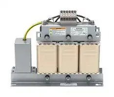
Power Line Filter, General Purpose, 520 VAC, 16 A, Three Phase, 1 Stage, Chassis Mount
- Manufacturer: TDK
- Product type:
- SVHC: Lead (25-Jun-2025)
- No. of Phases: Three Phase
- No. of Stages: 1 Stage
- Product Range: B84143V Series
- Current Rating: 16A
- Voltage Rating: 520VAC
- Filter Mounting: Chassis Mount
- Filter Applications: General Purpose
- Filter Input Terminals: Terminal Block
- Filter Output Terminals: Terminal Block
| Delivery and price | |
|---|---|
| Units per pack | 10 |
| Price | 396.7 € |
| Current stock | 10+ |
| Lead time | 30 days |
## **EMC filters**
3-line filters Sine-wave output filters 300/520 V AC, 4 A ... 390 A, 40 °C
**Series/Type: B84143V*R/S229** Date: November 2023
> TDK Electronics AG 2023. Reproduction, publication and dissemination of this publication, enclosures hereto and the information contained therein without TDK Electronics’ prior express consent is prohibited.
~~|~~ **Output filters B84143V*R/S229 Sine-wave output filters for 3-phase systems**
## **Sine-wave output filters for 3-phase systems Rated voltage VR: 300/520 V AC Rated current IR: 4 A to 390 A**
## **Construction** 3-line filters .
## **Features**
Reduction of motor noise and eddy current losses
- Generation of sinusoidal phase-to-phase voltage with low ripple
Schematic picture
- dv/dt reduction
- Easy to install
- Degree of protection[1)] : IP20 (4 A ... 33 A, 66 A) IP10 (50 A, 75 A, 95 A) IP00 (162 A ... 390 A)
- Optional housing for degree of protection IP21 can be ordered separately with ordering code B84143Q*R229
- Optimized for long motor cables[2)]
- Natural cooling
- Wiring between inverter and filter must be shorter than 10 meters!
- UL and cUL approval
- UL approved insulation system class 155 (F)
- Types 162 A, 230 A and 390 A contain a thermo switch
## **Typical applications**
Frequency converters for motor drives, e.g.
elevators
pumps
conveyer systems
HVAC systems (heating, ventilation and air conditioning)
## **Terminals**
Up to 95 A: Finger-safe terminals 162 A ... 390 A: Busbars
## **Marking**
Marking on component:
Manufacturer’s logo, ordering code, rated voltage, rated current, rated motor frequency, rated switch frequency, rated temperature, climatic category, date code Minimum data on packaging:
Manufacturer's logo, ordering code, quantity, date code
- 1) According to IEC 60529
- 2) The maximum permissible motor cable length depends on the application and must be checked.
Please read _Cautions and warnings_ and _Important notes_ at the end of this document.
**2** 11/23
**Output filters Sine-wave output filters for 3-phase systems**
**B84143V*R/S229**
## **Typical circuit diagrams**
Filters for 4 A ... 33 A
Filters for 50 A ... 95 A
Filters for 162 A ... 390 A
Please read _Cautions and warnings_ and _Important notes_ at the end of this document.
**3** 11/23
|**Output filters**|**B84143V*R/S229**|
|---|---|
|**Sine-wave output filters for 3-phase systems**||
## **Connection**
Converter: U1 Motor: U2 V1 V2 W1 W2
Connection order in case of terminal connection:
|U1|U2|V1|V2|W1|W2|
|---|---|---|---|---|---|
|Connection order in case<br>U2<br>V2<br>U1<br>V1||of busbar connection:<br>W2<br>upper connectors = motor side<br>W1<br>bottom connectors = converter side||||
|U1||||||
**Types 162 A, 230 A and 390 A contain a thermo switch**
Please read _Cautions and warnings_ and _Important notes_ at the end of this document.
**4** 11/23
**Output filters B84143V*R/S229 Sine-wave output filters for 3-phase systems**
## **Technical data and measuring conditions**
|Rated voltage VR|Rated voltage VR|Rated voltage VR|300/520 V AC(50/60 Hz)|
|---|---|---|---|
|Rated current IR|||Referred to 40°C rated temperature|
|Test voltage Vtest|||1500 V AC, 2 s (line/line)<br>2500 V AC, 2 s(lines/case)|
|Rated inductance LR|||See table "Characteristics and orderingcodes"|
|Rated capacitance CR|||Based on star connection independent of the real<br>used circuit; see table "Characteristics and ordering<br>codes"|
|Frequency<br>Motor fM<br>Pulse fP|||0 Hz ... 100 Hz<br>see table "Characteristics and orderingcodes"|
|Overload capability (thermal)|||1.5�IR for 1 minper hour|
|Max. dv/dt on filter input|||5 kV/μs(request for higher values)|
|Climatic category (IEC 60068-1)|||25/085/21(�25°C/+85°C/21 days dampheat test)|
|Approvals|||UL 1283, CSA C22.2 No.8|
|||||
||**WARNING!**|Hot surface! Risk of burns!||
## **Characteristics**[1)] **and ordering codes**
|IR<br>A|Terminal<br>cross section<br>mm2|Rtyp<br>mΩ|LR<br>mH|CR<br>μF|ΔV<br>%|fp<br>min.<br>kHz|fp<br>max.<br>kHz|PL2)<br>W|Approx.<br>weight<br>kg|Ordering code|
|---|---|---|---|---|---|---|---|---|---|---|
|VR=|300/520 V AC||||||||||
|4<br>6<br>11<br>16<br>25<br>33<br>50<br>66<br>75<br>95<br>162<br>230<br>390|6<br>6<br>6<br>10<br>10<br>10<br>35<br>35<br>35<br>35<br>40×3<br>40×3<br>40×4|390<br>290<br>67<br>31<br>25<br>16<br>8.9<br>5.5<br>5.5<br>4.5<br>1.53<br>1.7<br>1.15|12<br>8.5<br>4.5<br>3.0<br>2.5<br>1.8<br>1.2<br>0.95<br>0.86<br>0.75<br>0.4<br>0.3<br>0.18|2.2<br>2.2<br>3.3<br>5.6<br>10<br>10<br>15<br>30<br>30<br>30<br>90<br>90<br>180|12<br>12<br>12<br>12<br>12<br>12<br>13<br>13<br>13<br>14<br>15<br>16<br>19|3<br>3<br>3<br>3<br>3<br>3<br>3<br>3<br>3<br>3<br>2.4<br>2.4<br>2.4|10<br>10<br>10<br>10<br>10<br>10<br>10<br>8<br>8<br>8<br>6<br>6<br>4|60<br>100<br>90<br>80<br>140<br>160<br>220<br>250<br>310<br>400<br>550<br>900<br>1570|5<br>5<br>7<br>12<br>20<br>24<br>41<br>43<br>62<br>70<br>112<br>120<br>212|B84143V0004R229<br>B84143V0006R229<br>B84143V0011R229<br>B84143V0016R229<br>B84143V0025R229<br>B84143V0033R229<br>B84143V0050R229<br>B84143V0066R229<br>B84143V0075R229<br>B84143V0095R229<br>B84143V0162S229<br>B84143V0230S229<br>B84143V0390S229|
> 1) Approvals see table "Technical data and measuning conditions"
> 2) Estimated losses at IR and VR when running with an inverter at fp min
Please read _Cautions and warnings_ and _Important notes_ at the end of this document.
**5** 11/23
**Output filters Sine-wave output filters for 3-phase systems**
**B84143V*R/S229**
## **Application note**
**==> picture [152 x 155] intentionally omitted <==**
Wall mounting only possible for filters up to 95 A
Capacitors must be downside in case of wall mounting!
## **Convection space**
**==> picture [293 x 167] intentionally omitted <==**
**==> picture [293 x 145] intentionally omitted <==**
� General tolerances according to ISO 2768 cL Dimensions in mm
Please read _Cautions and warnings_ and _Important notes_ at the end of this document.
**6** 11/23
**B84143V*R/S229**
**Output filters Sine-wave output filters for 3-phase systems**
## **Dimensional drawings**
## **B84143V0004R229, B84143V0006R229 (4 A, 6 A)**
**==> picture [152 x 135] intentionally omitted <==**
**==> picture [90 x 65] intentionally omitted <==**
**==> picture [69 x 32] intentionally omitted <==**
**==> picture [193 x 60] intentionally omitted <==**
� General tolerances according to ISO 2768 cL Dimensions in mm
Please read _Cautions and warnings_ and _Important notes_ at the end of this document.
**7** 11/23
**Output filters Sine-wave output filters for 3-phase systems**
**B84143V*R/S229**
## **B84143V0011R229 (11 A)**
**==> picture [144 x 127] intentionally omitted <==**
**==> picture [91 x 61] intentionally omitted <==**
**==> picture [150 x 35] intentionally omitted <==**
� General tolerances according to ISO 2768 cL Dimensions in mm
Please read _Cautions and warnings_ and _Important notes_ at the end of this document.
**8** 11/23
**Output filters Sine-wave output filters for 3-phase systems**
**B84143V*R/S229**
## **B84143V0016R229 (16 A)**
**==> picture [69 x 31] intentionally omitted <==**
**==> picture [33 x 36] intentionally omitted <==**
**==> picture [115 x 121] intentionally omitted <==**
**==> picture [125 x 36] intentionally omitted <==**
**==> picture [37 x 38] intentionally omitted <==**
� General tolerances according to ISO 2768 cL Dimensions in mm
Please read _Cautions and warnings_ and _Important notes_ at the end of this document.
**9** 11/23
**Output filters**
**B84143V*R/S229**
## **Sine-wave output filters for 3-phase systems**
## **B84143V0025R229 (25 A)**
General tolerances according to ISO 2768 cL Dimensions in mm
## **B84143V0033R229 (33 A)**
General tolerances according to ISO 2768 cL Dimensions in mm
Please read _Cautions and warnings_ and _Important notes_ at the end of this document.
**10** 11/23
**B84143V*R/S229**
## **Output filters**
## **Sine-wave output filters for 3-phase systems**
## **B84143V0050R229 (50 A)**
**==> picture [207 x 148] intentionally omitted <==**
**==> picture [119 x 118] intentionally omitted <==**
� General tolerances according to ISO 2768 cL Dimensions in mm
## **B84143V0066R229 (66 A)**
**==> picture [117 x 105] intentionally omitted <==**
**==> picture [119 x 113] intentionally omitted <==**
**==> picture [76 x 59] intentionally omitted <==**
**==> picture [41 x 31] intentionally omitted <==**
� General tolerances according to ISO 2768 cL Dimensions in mm
Please read _Cautions and warnings_ and _Important notes_ at the end of this document.
**11** 11/23
**Output filters Sine-wave output filters for 3-phase systems**
**B84143V*R/S229**
## **B84143V0075R229 (75 A)**
� General tolerances according to ISO 2768 cL Dimensions in mm
Please read _Cautions and warnings_ and _Important notes_ at the end of this document.
**12** 11/23
**B84143V*R/S229**
**Output filters Sine-wave output filters for 3-phase systems**
## **B84143V0095R229 (95 A)**
**==> picture [179 x 165] intentionally omitted <==**
� General tolerances according to ISO 2768 cL Dimensions in mm
Please read _Cautions and warnings_ and _Important notes_ at the end of this document.
**13** 11/23
**Output filters Sine-wave output filters for 3-phase systems**
**B84143V*R/S229**
## **B84143V0162S229 (162 A)**
**==> picture [32 x 39] intentionally omitted <==**
**==> picture [263 x 138] intentionally omitted <==**
**==> picture [58 x 64] intentionally omitted <==**
**==> picture [34 x 35] intentionally omitted <==**
**==> picture [92 x 64] intentionally omitted <==**
� General tolerances according to ISO 2768 cL Dimensions in mm Busbar connection see section "Mechanical properties"
Please read _Cautions and warnings_ and _Important notes_ at the end of this document.
**14** 11/23
**Output filters Sine-wave output filters for 3-phase systems**
**B84143V*R/S229**
## **B84143V0230S229 (230 A)**
**==> picture [258 x 380] intentionally omitted <==**
**==> picture [98 x 147] intentionally omitted <==**
� General tolerances according to ISO 2768 cL Dimensions in mm Busbar connection see section "Mechanical properties"
Please read _Cautions and warnings_ and _Important notes_ at the end of this document.
**15** 11/23
**Output filters Sine-wave output filters for 3-phase systems**
**B84143V*R/S229**
## **B84143V0390S229 (390 A)**
**==> picture [258 x 373] intentionally omitted <==**
**==> picture [115 x 143] intentionally omitted <==**
� General tolerances according to ISO 2768 cL Dimensions in mm Busbar connection see section "Mechanical properties"
Please read _Cautions and warnings_ and _Important notes_ at the end of this document.
**16** 11/23
**Output filters Sine-wave output filters for 3-phase systems**
**B84143V*R/S229**
## **Cautions and warnings**
- Please note further advice in our website www.tdk-electronics.tdk.com/pemc_filters_gti
- It shall be ensured that only qualified persons (electricity specialists) are engaged on work such as planning, assembly, installation, operation, repair and maintenance. They must be provided with the corresponding documentation.
- Danger of electric shock: The products contain components that store an electric charge. Dangerous voltages can continue to exist at the product terminals for longer than five minutes even after the power has been switched off.
- The protective earth connections shall be the first to be made when the product is installed and secured against loosening by defined tightening torque. Remove them at last, when uninstalling. Depending on the magnitude of the leakage currents, the particular specifications for making the protective-earth connection must be observed.
- Impermissible overloading of the product, such as with circuits able to cause resonances, impermissible voltages at higher frequencies etc. can lead to bodily injury and death as well as cause substantial material damages (e.g. destruction of the product housing).
- The products must be protected in the application against impermissible exceeding of the rated currents by overcurrent protective devices.
- For leakage currents >10 mA, a fixed connection of the protective earth conductor to the public power grid is required. This means that connection via plug connectors is not permitted. The protective conductor must have a mini-mum cross-section of 10 mm[2] Cu or 16 mm[2] Al over its entire length. Alternatively, two separate protective conductors with the minimum cross-section specified in each case can also be connected.
- For leakage currents 3.5 mA < ILK[a)] ≤ 10 mA, the following solutions are possible:
- Stationary device with fixed connection
- Stationary device with type B plug-in connection (industrial plug-in connection according to IEC 60309) and cross-section ≥ 2.5 mm[2]
- Stationary device with type A plug-in connection (non-industrial plug-in device) and additional second protective earth connection
- Movable equipment with type A plug-in connection and additional second protective earth connection in premises with restricted access
- The products must be protected in the application against impermissible exceeding of the specification parameter.
- The converter output frequency must be within the specified range to avoid resonances and uncontrolled warming of the output chokes and output filters.
- The components can become very hot during operation, there is the risk of burns if touched. The product can remain hot for some time after the power is switched off!
- The products are only to be attached to the fixings or mounting holes provided for this purpose in accordance with the data sheet. It is not permitted for the product specified in the data sheet to assume a mechanical function in the final application, in particular any type of tension or pressure on the product must be prevented.
a) ILK = Leakage current
Please read _Cautions and warnings_ and _Important notes_ at the end of this document.
**17** 11/23
**Output filters Sine-wave output filters for 3-phase systems**
**B84143V*R/S229**
## **Display of ordering codes for TDK Electronics products**
The ordering code for one and the same product can be represented differently in data sheets, data books, other publications, on the company website, or in order-related documents such as shipping notes, order confirmations and product labels. The varying representations of the ordering codes are due to different processes employed and do not affect the specifications of the respective products.
Detailed information can be found on the Internet under www.tdk-electronics.tdk.com/orderingcodes.
The table below summarizes the safety instructions that must be observed without fail. A detailed description can be found in the relevant chapters of the databook.
|**Topic**|**Instructions**|**Reference chapter**<br>**(data book),**<br>**paragraph**|
|---|---|---|
|Selecting a filter|When selecting a filter, it is mandatory to observe the<br>rated data of the equipment (such as its rated input cur-<br>rent, rated voltage, harmonic content etc.) as well as<br>the deratinginstructions in Chapters 9 and 10.|Selection guide for<br>converter filters|
|Rated voltage|When power distribution systems deviating from the<br>symmetric TN-S system is to check the suitability of the<br>filters and the allowed voltages including the fault<br>cases.|Power distribution<br>systems,<br>7|
|Protection from<br>residual voltages<br>Discharge resistors|Active parts must be discharged within 5 s to a volt-<br>age of less than 60 V (or 50 µC). If this limit cannot<br>be observed due to the operating mode, the hazard-<br>ous point must be permanently marked in a clearly<br>visible way.|Safety regulations,<br>6.1|
||Filters which are not permanently connected (e.g.<br>when the test voltage is applied to the filter at the<br>incoming goods inspection) must be discharged after<br>the voltage has been switched off.|Safety regulations,<br>6.2|
|Installing and<br>removing of filters<br>Installation|When installing and removing our filters, a voltage-free<br>state must be set up and secured with observance<br>of the five safety rules described in EN 50110-1.|Safety regulations,<br>6.4|
|Use in IT systems|The special features of the IT system ("first fault case"<br>and other fault cases) shall be observed.|Power distribution<br>system<br>(network types),<br>7.6|
|Safety notes on<br>leakage currents|The filter leakage currents specified in the data book<br>are intended for user information only.The maximum<br>leakage current of the entire electrical equipment or<br>appliance has to be limited for safety reasons. Please<br>obtain the applicable limits for your application from<br>the relevant regulations, provisions and standards.|Leakage current,<br>8.4<br>Leakage current,<br>8.6|
Please read _Cautions and warnings_ and _Important notes_ at the end of this document.
**18** 11/23
|**Output filters**<br>**B84143V*R/S229**|**Output filters**<br>**B84143V*R/S229**|**Output filters**<br>**B84143V*R/S229**|
|---|---|---|
|**Sine-wave output filters for 3-phase systems**|||
||||
|**Topic**|**Instructions**|**Reference chapter**<br>**(data book),**<br>**paragraph**|
|Voltage derating<br>Hazards caused by<br>overloading the<br>filters|If the permissible limits for the higher-frequency volt-<br>ages at the filter are exeeded, the filter may be<br>damaged or destroyed.|Voltage derating,<br>9.8|
|Current derating at<br>elevated ambient<br>temperatures|Non-observance of the current derating may lead to<br>overheating and consequently represents a fire<br>hazard.|Current derating,<br>10.1|
|Protective earth<br>connection at<br>operating currents<br>>250 A|For operating currents greater than 250 A, we re-<br>commend the PE connection to be set up between the<br>feed (filter: line) and output (filter: load) not via the<br>PE terminal bolt in the filter housing.|Mounting<br>instructions,<br>point 2|
|Mounting position|Note the mounting position of the filters! It must al-<br>ways be ensured that natural convection is not im-<br>paired.|Mounting<br>instructions,<br>point 13|
|Long motor cables|Long motor cables cause parasitic currents in the in-<br>stallation. The cable lengths indicated for the output<br>chokes and output filters serve for orientation. The user<br>must check the technical parameters and especially<br>the choke temperatures for the respective application.|Mounting<br>instructions,<br>point 15|
Please read _Cautions and warnings_ and _Important notes_ at the end of this document.
**19** 11/23
**Output filters Sine-wave output filters for 3-phase systems**
**B84143V*R/S229**
## **Symbols and terms**
|Symbol|English|German|
|---|---|---|
|α<br>CR<br>CX<br>CY<br>ΔV<br>dv/dt<br>f<br>fM<br>fP<br>fR<br>fres<br>IC<br>ILK<br>Imax<br>IN<br>Iop<br>Ipk<br>Iq<br>IR<br>IS<br>L<br>LR<br>Lstray<br>PL<br>R<br>Ris<br>Rtyp<br>TA<br>Tmax<br>Tmin<br>TR<br>uk<br>Veff<br>VK<br>VLE<br>VN<br>VR<br>Vpeak<br>Vtest|Insertion loss<br>Rated capacitance<br>Capacitance X capacitor<br>Capacitance Y capacitor<br>Voltage drop (input to output)<br>Rate of voltage rise<br>Frequency<br>Converter output frequency<br>Pulse frequency<br>Rated frequency<br>Resonant frequency<br>Current through capacitor<br>Filter leakage current<br>Maximum current<br>Nominal current<br>Operating current (design current)<br>Rated peak withstand current<br>Capacitive reactive current<br>Rated current<br>Interference current<br>Inductance<br>Rated inductance<br>Stray inductance<br>Power loss<br>Resistance<br>Insulation resistance<br>DC resistance, typical value<br>Ambient temperature<br>Upper category temperature<br>Lower category temperature<br>Rated temperature<br>Referred voltage drop in %<br>RMS voltage<br>Voltage drop<br>Voltage line to earth; voltage line to ground<br>Nominal voltage<br>Rated voltage<br>Peak voltage<br>Test voltage|Einfügungsdämpfung<br>Bemessungskapazität<br>Kapazität X-Kondensator<br>Kapazität Y-Kondensator<br>Spannungsabfall (Eingang zu Ausgang)<br>Spannungsanstiegsgeschwindigkeit<br>Frequenz<br>Motorfrequenz<br>Pulsfrequenz<br>Bemessungsfrequenz<br>Resonanzfrequenz<br>Strom durch Kondensator<br>Filter-Ableitstrom<br>Maximalstrom<br>Nennstrom<br>Betriebsstrom<br>Bemessungsstoßstromfestigkeit<br>Kapazitiver Blindstrom<br>Bemessungsstrom<br>Störstrom<br>Induktivität<br>Bemessungsinduktivität<br>Streuinduktivität<br>Verlustleistung<br>Widerstand<br>Isolationswiderstand<br>Gleichstromwiderstand typisch<br>Umgebungstemperatur<br>Obere Kategorietemperatur<br>Untere Kategorietemperatur<br>Bemessungstemperatur<br>Bezogener Spannungsabfall in %<br>Effektivspannung<br>Spannungsabfall<br>Spannung Phase zu Erdpotential<br>Nennspannung<br>Bemessungsspannung<br>Spitzenspannung<br>Prüfspannung|
Please read _Cautions and warnings_ and _Important notes_ at the end of this document.
**20** 11/23
**B84143V*R/S229**
## **Output filters Sine-wave output filters for 3-phase systems**
|Symbol|English|German|
|---|---|---|
|VX<br>VY<br>XL<br>Z<br>|Z||Voltage over X capacitor<br>Voltage over Y capacitor<br>Inductive reactance<br>Impedance<br>Impedance, absolute value|Spannung über X-Kondensator<br>Spannung über Y-Kondensator<br>Induktiver Blindwiderstand<br>Scheinwiderstand<br>Scheinwiderstand (Betragswert)|
Please read _Cautions and warnings_ and _Important notes_ at the end of this document.
**21** 11/23
## **Important notes**
The following applies to all products named in this publication:
1. Some parts of this publication contain **statements about the suitability of our products for certain areas of application** . These statements are based on our knowledge of typical requirements that are often placed on our products in the areas of application concerned. We nevertheless expressly point out **that such statements cannot be regarded as binding statements about the suitability of our products for a particular customer application.** As a rule, we are either unfamiliar with individual customer applications or less familiar with them than the customers themselves. For these reasons, it is always ultimately incumbent on the customer to check and decide whether a product with the properties described in the product specification is suitable for use in a particular customer application.
2. We also point out that **in individual cases, a malfunction of electronic components or failure before the end of their usual service life cannot be completely ruled out in the current state of the art, even if they are operated as specified.** In customer applications requiring a very high level of operational safety and especially in customer applications in which the malfunction or failure of an electronic component could endanger human life or health (e.g. in accident prevention or life-saving systems), it must therefore be ensured by means of suitable design of the customer application or other action taken by the customer (e.g. installation of protective circuitry or redundancy) that no injury or damage is sustained by third parties in the event of malfunction or failure of an electronic component.
3. **The warnings, cautions and product-specific notes must be observed** .
4. In order to satisfy certain technical requirements, **some of the products described in this publication may contain substances subject to restrictions in certain jurisdictions (e.g. because they are classed as hazardous)** . Useful information on this will be found in our Material Data Sheets on the Internet (www.tdk-electronics.tdk.com/material). Should you have any more detailed questions, please contact our sales offices.
5. We constantly strive to improve our products. Consequently, **the products described in this publication may change from time to time** . The same is true of the corresponding product specifications. Please check therefore to what extent product descriptions and specifications contained in this publication are still applicable before or when you place an order. We also **reserve the right to discontinue production and delivery of products** . Consequently, we cannot guarantee that all products named in this publication will always be available. The aforementioned does not apply in the case of individual agreements deviating from the foregoing for customer-specific products.
6. Unless otherwise agreed in individual contracts, **all orders are subject to our General Terms and Conditions of Supply** .
**22** 11/21
## **Important notes**
7. **Our manufacturing sites serving the automotive business apply the IATF 16949 standard** . The IATF certifications confirm our compliance with requirements regarding the quality management system in the automotive industry. Referring to customer requirements and customer specific requirements (“CSR”) TDK always has and will continue to have the policy of respecting individual agreements. Even if IATF 16949 may appear to support the acceptance of unilateral requirements, we hereby like to emphasize that **only requirements mutually agreed upon can and will be implemented in our Quality Management System.** For clarification purposes we like to point out that obligations from IATF 16949 shall only become legally binding if individually agreed upon.
8. The trade names EPCOS, CarXield, CeraCharge, CeraDiode, CeraLink, CeraPad, CeraPlas, CSMP, CTVS, DeltaCap, DigiSiMic, FilterCap, FormFit, InsuGate, LeaXield, MediPlas, MiniBlue, MiniCell, MKD, MKK, ModCap, MotorCap, PCC, PhaseCap, PhaseCube, PhaseMod, PhiCap, PiezoBrush, PlasmaBrush, PowerHap, PQSine, PQvar, SIFERRIT, SIFI, SIKOREL, SilverCap, SIMDAD, SiMic, SIMID, SineFormer, SIOV, ThermoFuse, WindCap, XieldCap are **trademarks registered or pending** in Europe and in other countries. Further information will be found on the Internet at www.tdk-electronics.tdk.com/trademarks.
Release 2023-08
**23** 11/21
Updated at June 10, 2026
TDK Corporation is a globally recognized leader in electronic components and magnetic materials. Founded in 1935 to commercialize ferrites, the Tokyo-based company has evolved into a comprehensive manufacturer of high-performance passive components, sensors, and power electronics. TDK’s advanced materials technology serves as the foundation for its extensive portfolio, driving innovation across automotive, industrial, consumer electronics, and communication technologies. Our selection of TDK components heavily features their industry-leading passive components, with a primary focus on magnetics. TDK excels in manufacturing reliable inductive solutions, offering a vast array of power inductors and RF inductors optimized for demanding power management and high-frequency applications. Furthermore, their expertise in electromagnetic compatibility is showcased through a comprehensive range of EMC and RFI suppression products. This includes common mode chokes, power line filters, and specialized shielding materials designed to ensure superior signal integrity in complex designs. Beyond inductors and filtering components, TDK provides robust circuit protection and sensing solutions essential for modern engineering. The portfolio includes precision temperature sensing and compensation NTC thermistors, alongside TVS varistors and inrush current limiting components that safeguard sensitive electronics. Complemented by fixed value inductors, supercapacitors, and charging coils, TDK's versatile product offering delivers the reliability and performance required for sophisticated circuit design.
About Novapart
Novapart is a B2B electronic component broker specialising in stock shortages and cost reduction. We source hard-to-find parts and identify compliant alternatives across a catalogue of 410,000+ components from 500+ manufacturers.
Learn more →Stock Shortage Specialist
When a component is unavailable, discontinued or has an unacceptable lead time, we tap into our network of vetted European and Asian distributors to source what you need — without compromising on quality or traceability.
Request a quote →Compliant Alternatives
We identify pin-to-pin, electrically equivalent substitutes that meet the same certifications (RoHS, AEC-Q100, REACH) as your original specification — validated against datasheets, not just part numbers. Often at a lower cost.
BOM Analysis service →