
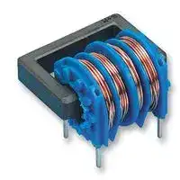


B82731H2112A030
Choke, Common Mode, 10 mH, 1.1 A, Through Hole, 4 Pins, B82731M/H Series
- Manufacturer: TDK
- Product type: Radial Leaded Common Mode Chokes / Filters
- Inductance:10mH; Rated Current:1.1A; Product Range:B82731M/H Series; SVHC:No SVHC (07-Jul-2017); DC Current Max:1.1A; DC Current Rating:1.1A; DC Resistance Max:400mohm; External Depth:20mm; E
- SVHC: No SVHC (25-Jun-2025)
- Inductance: 10mH
- Product Range: B82731H Series
- DC Current Rating: 1.1A
- DC Resistance Max: 0.4ohm
- Operating Temperature Max: 125°C
- Operating Temperature Min: -40°C
| Delivery and price | |
|---|---|
| Units per pack | 1600 |
| Price | 1.04 € |
| Current stock | 10+ |
| Lead time | 30 days |
## **Power line chokes** Current-compensated D core double chokes 250 V AC, 3.3 … 100 mH, 0.35 … 1.8 A, +40 °C **Series/Type: B82731M/H** Date: February 2025 > TDK Electronics AG 2025. Reproduction, publication and dissemination of this publication, enclosures hereto and the information contained therein without TDK Electronics’ prior express consent is prohibited. ## **Power line chokes B82731M/H** ~~LT~~ **Current-compensated D core double chokes** **Rated voltage 250 V AC Rated current 0.35 ... 1.8 A / +40 °C Nominal inductance 3.3 ... 100 mH** ## **Construction** - Current-compensated double choke - Closed rectangular ferrite core - Closed plastic coil former (UL 94 V-0)[1) ] **==> picture [49 x 9] intentionally omitted <==** **----- Start of picture text -----**<br> B82731M<br>**----- End of picture text -----**<br> - Without encapsulation - 2-section winding - Clearance and creepage distances 3 mm ## **Features** - High resonance frequency due to 2-section winding - Approx. 1% stray inductance for symmetrical interference suppression - Low leakage due to closed core shape - High pulse strength - Low whirring noise **==> picture [49 x 9] intentionally omitted <==** **----- Start of picture text -----**<br> B82731H<br>**----- End of picture text -----**<br> - Suitable for wave soldering - Design complies with EN 60938-2 (VDE 0565-2) and UL 1283 - UL[2) ] and ENEC (VDE) approvals W & - Recyclable owing to omission of encapsulation and glue - RoHS-compatible ## **Applications** - Suppression of common-mode interferences - Compact switch-mode power applications - Electronic ballasts in lamps ## **Terminals** - Base material CuNi18Zn20 - Layer composition Ni, Sn - Hot-dipped - Pins 0.6 0.6 (mm) - Lead spacing 10 12.5 (mm) ## **Marking** B82731M: Product brand, nominal inductance, rated current, ordering code, approval signs, date of manufacture (YYWW) B82731H: Product brand, ordering code ## **Delivery mode** - Blister tray in cardboard box - Delivery in tube magazine is available on request - 1) Additionally certified values: Glow wire flammability index (GWFI to IEC 60695-2-12): +850 °C Glow wire ignition temperature (GWIT to IEC 60695-2-13): +775 °C Glow wire test (GWT to IEC 60695-2-11): +750 °C, 2 s / 850 °C, 30 s Comparative tracking index (CTI to IEC 60112): 175 V Ball pressure test (BP to IEC 60695-10-2): +125 °C - 2) UL approval with 300 V AC. Please read _Cautions and warnings_ and _Important notes_ at the end of this document. **2** 2/25 **B82731M/H** **Power line chokes Current-compensated D core double chokes** **Dimensional drawings and pin configurations** Vertical version (B82731M) Horizontal version (B82731H) **==> picture [83 x 66] intentionally omitted <==** **==> picture [39 x 98] intentionally omitted <==** **==> picture [65 x 77] intentionally omitted <==** **==> picture [138 x 63] intentionally omitted <==** **==> picture [167 x 85] intentionally omitted <==** Please read _Cautions and warnings_ and _Important notes_ at the end of this document. **3** 2/25 **B82731M/H** **Power line chokes Current-compensated D core double chokes** ## **Technical data and measuring conditions** |Rated voltage VR|250 V AC (50/60 Hz)| |---|---| |Test voltage Vtest|1500 V AC, 2 s(line/line)| |Rated temperature TR|+40C| |Rated current IR|Referred to 50 Hz and rated temperature| |Nominal inductance LN|Measured with Agilent 4284A at 10 kHz, 0.1 mA, +20 °C.<br>Inductance is specified per winding.| |Inductance tolerance|–30/+50% at +20 °C| |Inductance decreaseL/L0|< 10% at DC magnetic bias with IR, +20 °C| |Strayinductance Lstray,typ|Measured with Agilent 4284A at 10 kHz, 5 mA, +20C, typ. values| |DC resistance Rtyp|Measured at +20 °C, typical values, specified per winding| |Solderability (lead-free)|Sn96.5Ag3.0Cu0.5: +(2453) °C, (30.3) s<br>Wetting of soldering area95%<br>(to IEC 60068-2-20, test Ta)| |Resistance to soldering heat<br>(wave soldering)|+(2605) °C, (101) s<br>(to IEC 60068-2-20, test Tb)| |Climatic category|40/125/56 (to IEC 60068-1)| |Storage conditions (packaged)|–25 °C … +40 °C,75% RH| |Weight|Approx. 8g| |Approvals|IEC EN 60938-2, UL 1283 (E70122)| ## **Characteristics and ordering codes** |IR<br>A|LN<br>mH|Lstray,typ<br>H|Rtyp<br>m|Ordering code<br>Vertical version<br>Horizontal version|Ordering code<br>Vertical version<br>Horizontal version|Approvals|Approvals| |---|---|---|---|---|---|---|---| |0.35<br>0.4<br>0.5<br>0.6<br>0.7<br>0.8<br>0.9<br>1.1<br>1.3<br>1.8|100<br>68<br>47<br>39<br>27<br>22<br>15<br>10<br>6.8<br>3.3|1000<br>700<br>470<br>390<br>270<br>220<br>150<br>100<br>70<br>35|4500<br>3000<br>2000<br>1500<br>1000<br>800<br>600<br>400<br>280<br>140|B82731M2351A030<br>B82731M2401A033<br>B82731M2501A030<br>B82731M2601A030<br>B82731M2701A030<br>B82731M2801A030<br>B82731M2901A030<br>B82731M2112A030<br>B82731M2132A030<br>B82731M2182A030|B82731H2351A030<br>B82731H2401A033<br>B82731H2501A030<br>B82731H2601A030<br>B82731H2701A030<br>B82731H2801A030<br>B82731H2901A030<br>B82731H2112A030<br>B82731H2132A030<br>B82731H2182A030|<br><br><br><br><br><br><br><br><br>|<br><br><br><br><br><br><br><br><br>| ## = approval granted Sample kit available. Ordering code: B82731X001 For more information refer to chapter “Sample kits”. Please read _Cautions and warnings_ and _Important notes_ at the end of this document. **4** 2/25 **B82731M/H** **Power line chokes Current-compensated D core double chokes** **Impedance |Z| versus frequency f** measured with windings in parallel at +20 °C, typical values **Current derating Iop/IR versus ambient temperature TA** **==> picture [38 x 105] intentionally omitted <==** Please read _Cautions and warnings_ and _Important notes_ at the end of this document. **5** 2/25 ## **Cautions and warnings** - Please note the recommendations in our Inductors data book (latest edition), online catalogs and in the data sheets. - Particular attention should be paid to the derating curves, if given. Derating applies in the case the ambient temperature in application exceeds the rated temperature of the component. - Ensure the operation temperature of the component in application not to exceed the maximum specified value or the upper climatic category temperature. - The soldering conditions should also be observed. Temperatures quoted in relation to wave soldering refer to the pins only. Temperatures specified in relation to reflow soldering can also refer to the pins or terminals for products with larger thermal mass, as in such cases, the temperature difference to the top of the component is too big (e.g., high proportion of core within the component). - If the components are to be washed varnished it is necessary to check whether the washing varnish agent that is used has a negative effect on the wire insulation, any plastics that are used, or on glued joints. It is possible for washing varnish agent residues to have a negative effect in the long−term on wire insulation. - Washing processes may damage the product due to the possible static or cyclic mechanical loads (e.g., ultrasonic cleaning). They may cause cracks to develop on the product and its parts, which might lead to reduced reliability or lifetime. - The following points must be observed if the components are potted, sealed, or varnished in customer applications: - Many potting, sealing, or varnishing materials shrink as they harden. They therefore exert a pressure on the plastic housing or core. This pressure can have a deleterious effect on electrical properties, and in extreme cases can damage the core or plastic housing mechanically. - It is necessary to check whether the potting, sealing or varnishing materials used attack or destroy the wire insulation, plastics, or glue. - The effect of the potting, sealing, or varnishing materials may change the high−frequency behavior of the components. - Magnetic core materials such as ferrites are sensitive to direct impact. This can cause the core material to flake or lead to breakage of the magnetic core material. - Any type of tension or pressure on the product may result in damage and affect its functionality and reliability. - The products are only to be attached to fixings or mounting holes provided for this purpose in accordance with the data sheet. - If additional mechanical forces are applied to the component, e.g., application of gap pads, it is necessary to check whether they attack or destroy any part of the component. - It is not permitted for the product specified in the data sheet to assume a mechanical function in the final application. - Inductance value can drop if external metallic or magnetic parts will be put close to the coil or into the air gap of the coil or core or magnetic material. - Even for customer-specific products, conclusive validation of the component in the circuit can only be carried out by the customer. ## Release 2024-08-08 Please read _Cautions and warnings_ and _Important notes_ at the end of this document. **6** 2/25 **Cautions and warnings** ## **Display of ordering codes for TDK Electronics products** The ordering code for one and the same product can be represented differently in data sheets, data books, other publications, on the company website, or in order-related documents such as shipping notes, order confirmations and product labels. **The varying representations of the ordering codes are due to different processes employed and do not affect the specifications of the respective products** . Detailed information can be found on the Internet under www.tdk-electronics.tdk.com/orderingcodes. Please read _Cautions and warnings_ and _Important notes_ at the end of this document. **7** 2/25 ## **Important notes** The following applies to all products named in this publication: 1. Some parts of this publication contain **statements about the suitability of our products for certain areas of application** . These statements are based on our knowledge of typical requirements that are often placed on our products in the areas of application concerned. We nevertheless expressly point out **that such statements cannot be regarded as binding statements about the suitability of our products for a particular customer application** . As a rule we are either unfamiliar with individual customer applications or less familiar with them than the customers themselves. For these reasons, it is always ultimately incumbent on the customer to check and decide whether a product with the properties described in the product specification is suitable for use in a particular customer application. 2. We also point out that **in individual cases, a malfunction of electronic components or failure before the end of their usual service life cannot be completely ruled out in the current state of the art, even if they are operated as specified** . In customer applications requiring a very high level of operational safety and especially in customer applications in which the malfunction or failure of an electronic component could endanger human life or health (e.g. in accident prevention or life-saving systems), it must therefore be ensured by means of suitable design of the customer application or other action taken by the customer (e.g. installation of protective circuitry or redundancy) that no injury or damage is sustained by third parties in the event of malfunction or failure of an electronic component. 3. **The warnings, cautions and product-specific notes must be observed** . 4. In order to satisfy certain technical requirements, **some of the products described in this publication may contain substances subject to restrictions in certain jurisdictions (e.g. because they are classed as hazardous)** . Useful information on this will be found in our Material Data Sheets on the Internet (www.tdk-electronics.tdk.com/material). Should you have any more detailed questions, please contact our sales offices. 5. We constantly strive to improve our products. Consequently, **the products described in this publication may change from time to time** . The same is true of the corresponding product specifications. Please check therefore to what extent product descriptions and specifications contained in this publication are still applicable before or when you place an order. We also **reserve the right to discontinue production and delivery of products** . Consequently, we cannot guarantee that all products named in this publication will always be available. The aforementioned does not apply in the case of individual agreements deviating from the foregoing for customer-specific products. 6. Unless otherwise agreed in individual contracts, **all orders are subject to our General Terms and Conditions of Supply** . **8** 2/25 ## **Important notes** 7. **Our manufacturing sites serving the automotive business apply the IATF 16949 standard** . The IATF certifications confirm our compliance with requirements regarding the quality management system in the automotive industry. Referring to customer requirements and customer specific requirements (“CSR”) TDK always has and will continue to have the policy of respecting individual agreements. Even if IATF 16949 may appear to support the acceptance of unilateral requirements, we hereby like to emphasize that **only requirements mutually agreed upon can and will be implemented in our Quality Management System** . For clarification purposes we like to point out that obligations from IATF 16949 shall only become legally binding if individually agreed upon. 8. The trade names EPCOS, CarXield, CeraCharge, CeraDiode, CeraLink, CeraPad, CeraPlas, CSMP, CTVS, DeltaCap, DigiSiMic, FilterCap, FormFit, InsuGate, LeaXield, MediPlas, MiniBlue, MiniCell, MKD, MKK, ModCap, MotorCap, PCC, PhaseCap, PhaseCube, PhaseMod, PhiCap, PiezoBrush, PlasmaBrush, PowerHap, PQSine, PQvar, SIFERRIT, SIFI, SIKOREL, SilverCap, SIMDAD, SiMic, SIMID, SineFormer, SIOV, SurfIND, ThermoFuse, WindCap, XieldCap are **trademarks registered or pending** in Europe and in other countries. Further information will be found on the Internet at www.tdk-electronics.tdk.com/trademarks. ## Release 2024-02 **9** 2/25
Updated at June 10, 2026
TDK Corporation is a globally recognized leader in electronic components and magnetic materials. Founded in 1935 to commercialize ferrites, the Tokyo-based company has evolved into a comprehensive manufacturer of high-performance passive components, sensors, and power electronics. TDK’s advanced materials technology serves as the foundation for its extensive portfolio, driving innovation across automotive, industrial, consumer electronics, and communication technologies. Our selection of TDK components heavily features their industry-leading passive components, with a primary focus on magnetics. TDK excels in manufacturing reliable inductive solutions, offering a vast array of power inductors and RF inductors optimized for demanding power management and high-frequency applications. Furthermore, their expertise in electromagnetic compatibility is showcased through a comprehensive range of EMC and RFI suppression products. This includes common mode chokes, power line filters, and specialized shielding materials designed to ensure superior signal integrity in complex designs. Beyond inductors and filtering components, TDK provides robust circuit protection and sensing solutions essential for modern engineering. The portfolio includes precision temperature sensing and compensation NTC thermistors, alongside TVS varistors and inrush current limiting components that safeguard sensitive electronics. Complemented by fixed value inductors, supercapacitors, and charging coils, TDK's versatile product offering delivers the reliability and performance required for sophisticated circuit design.
About Novapart
Novapart is a B2B electronic component broker specialising in stock shortages and cost reduction. We source hard-to-find parts and identify compliant alternatives across a catalogue of 410,000+ components from 500+ manufacturers.
Learn more →Stock Shortage Specialist
When a component is unavailable, discontinued or has an unacceptable lead time, we tap into our network of vetted European and Asian distributors to source what you need — without compromising on quality or traceability.
Request a quote →Compliant Alternatives
We identify pin-to-pin, electrically equivalent substitutes that meet the same certifications (RoHS, AEC-Q100, REACH) as your original specification — validated against datasheets, not just part numbers. Often at a lower cost.
BOM Analysis service →