
Image not available
Illustrative purposes only

B66506P0000X197
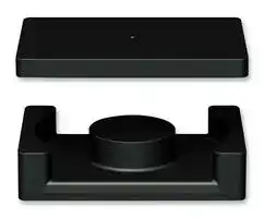
Transformer Cores, I, I30/3, N97, 31.5 mm, 108 mm²
⚠️ Reference pricing provided. In case of supply shortages, we will connect you with our trusted procurement partners to ensure your project's continuity.
- Manufacturer: EPCOS
- Product type: Transformer Cores
- Core Size: I30/3
- Core Type: I
- Product Range: B66506P
- Core Material Grade: N97
- Inductance Factor Al: 5.75µH
- Effective Magnetic Path Length: 31.5mm
- Ae Effective Cross Section Area: 108mm²
| Delivery and price | |
|---|---|
| Units per pack | 288 |
| Price | 1.26 € |
| Current stock | 10+ |
| Lead time | 30 days |
Datasheet

## **Ferrites and accessories** ## EEQ 30, EIQ 30 Core set **Series/Type: B66506G, B66506P** Date: June 2013 > EPCOS AG 2015. Reproduction, publication and dissemination of this publication, enclosures hereto and the information contained therein without EPCOS' prior express consent is prohibited. EPCOS AG is a TDK Group Company. ~~Lo~~ **EQ 30/8 Core B66506** ## **Core set EEQ 30 Combination: EQ 30/8 with EQ 30/8** **EQ 30/8** - To IEC 62317-9 - Optimized cross section - Small overall footprint (core and winding) - Less EMI - Minimized winding length - Delivery mode: single units ## **Magnetic characteristics** (per set) - l/A = 0.426 mm[–1] le = 46 mm Ae = 108 mm[2] Amin = 95 mm[2] Ve = 4970 mm[3] ## **Approx. weight:** 23 g/set ## **Ungapped** |Material|ALvalue<br>nH|e|PV<br>W/set|Ordering code| |---|---|---|---|---| |N92|327025%|1110|< 4.25 (200 mT, 100 kHz, 100 °C)|B66506G0000X192| |N49|333025%|1130|< 1.43 ( 50 mT, 500 kHz, 100 °C)|B66506G0000X149| |N87|430025%|1470|< 2.70 (200 mT, 100 kHz, 100 °C)|B66506G0000X187| |N97|450025%|1540|< 2.50 (200 mT, 100 kHz, 100 °C)|B66506G0000X197| Please read _Cautions and warnings_ and _Important notes_ at the end of this document. **2** 06/13 ## **EQ 30/8 with I 30/3 Core** **B66506** ## **Core set EIQ 30 Combination: EQ 30/8 with I 30/3** ## **EQ 30/8** ## **I 30/3** - To IEC 62317-9 - Optimized cross section - Small overall footprint (core and winding) - Less EMI - Minimized winding length - Delivery mode: single units ## **Magnetic characteristics** (per set) - l/A = 0.29 mm[–1] le = 31.5 mm Ae = 108.0 mm[2] Amin = 95.0 mm[2] - Ve = 3400 mm[3] ## **Approx. weight:** 21.5 g/set ## **Ungapped** |Material|ALvalue<br>nH|e|PV<br>W/set|Ordering code| |---|---|---|---|---| |N49|435025%|1000|< 1.10 ( 50 mT, 500 kHz, 100 °C)|B66506G0000X149 (EQ core)<br>B66506P0000X149 (I core)| |N92|445025%|1020|< 3.40 (200 mT, 100 kHz, 100 °C)|B66506G0000X192 (EQ core)<br>B66506P0000X192 (I core)| |N87|560025%|1300|< 2.15 (200 mT, 100 kHz, 100 °C)|B66506G0000X187 (EQ core)<br>B66506P0000X187 (I core)| |N97|575025%|1330|< 2.00 (200 mT, 100 kHz, 100 °C)|B66506G0000X197 (EQ core)<br>B66506P0000X197 (I core)| Please read _Cautions and warnings_ and _Important notes_ at the end of this document. **3** 06/13 **Ferrites and accessories** ~~LT~~ **Cautions and warnings** ## **Mechanical stress and mounting** Ferrite cores have to meet mechanical requirements during assembling and for a growing number of applications. Since ferrites are ceramic materials one has to be aware of the special behavior under mechanical load. As valid for any ceramic material, ferrite cores are brittle and sensitive to any shock, fast changing or tensile load. Especially high cooling rates under ultrasonic cleaning and high static or cyclic loads can cause cracks or failure of the ferrite cores. For detailed information see chapter _“Definitions”_ , section 8.1. ## **Effects of core combination on AL value** Stresses in the core affect not only the mechanical but also the magnetic properties. It is apparent that the initial permeability is dependent on the stress state of the core. The higher the stresses are in the core, the lower is the value for the initial permeability. Thus the embedding medium should have the greatest possible elasticity. For detailed information see chapter _“Definitions”_ , section 8.2. ## **Heating up** Ferrites can run hot during operation at higher flux densities and higher frequencies. ## **NiZn-materials** The magnetic properties of NiZn-materials can change irreversible in high magnetic fields. ## **Processing notes** - The start of the winding process should be soft. Else the flanges may be destroid. - To strong winding forces may blast the flanges or squeeze the tube that the cores can no more be mount. - To long soldering time at high temperature (>300 °C) may effect coplanarity or pin arrangement. - Not following the processing notes for soldering of the J-leg terminals may cause solderability problems at the transformer because of pollution with Sn oxyd of the tin bath or burned insulation of the wire. For detailed information see chapter _“Processing notes”_ , section 8.2. - The dimensions of the hole arrangement have fixed values and should be understood as a recommendation for drilling the printed circuit board. For dimensioning the pins, the group of holes can only be seen under certain conditions, as they fit into the given hole arrangement. To avoid problems when mounting the transformer, the manufacturing tolerances for positioning the customers’ drilling process must be considered by increasing the hole diameter. **4** a **4** 06/13 ## ~~LO~~ **Ferrites and accessories Symbols and terms** |Symbol|Meaning|Unit| |---|---|---| |A<br>Ae<br>AL<br>AL1<br>Amin<br>AN<br>AR<br>B<br>B<br>Bˆ<br>Bˆ<br>BDC<br>BR<br>BS<br>C0<br>CDF<br>DF<br>d<br>Ea<br>f<br>fcutoff<br>fmax<br>fmin<br>fr<br>fCu<br>g<br>H<br>Hˆ<br>HDC<br>Hc<br>h<br>h/i 2<br>I<br>IDC<br>Iˆ<br>J<br>k<br>k3<br>k3c<br>L|Cross section of coil<br>Effective magnetic cross section<br>Inductance factor; AL= L/N2<br>Minimum inductance at defined high saturation ( a)<br>Minimum core cross section<br>Winding cross section<br>Resistance factor; AR= RCu/N2<br>RMS value of magnetic flux density<br>Flux density deviation<br>Peak value of magnetic flux density<br>Peak value of flux density deviation<br>DC magnetic flux density<br>Remanent flux density<br>Saturation magnetization<br>Winding capacitance<br>Core distortion factor<br>Relative disaccommodation coefficient DF = d/i<br>Disaccommodation coefficient<br>Activation energy<br>Frequency<br>Cut-off frequency<br>Upper frequency limit<br>Lower frequency limit<br>Resonance frequency<br>Copper filling factor<br>Air gap<br>RMS value of magnetic field strength<br>Peak value of magnetic field strength<br>DC field strength<br>Coercive field strength<br>Hysteresis coefficient of material<br>Relative hysteresis coefficient<br>RMS value of current<br>Direct current<br>Peak value of current<br>Polarization<br>Boltzmann constant<br>Third harmonic distortion<br>Circuit third harmonic distortion<br>Inductance|mm2<br>mm2<br>nH<br>nH<br>mm2<br>mm2<br>= 10–6<br>Vs/m2, mT<br>Vs/m2, mT<br>Vs/m2, mT<br>Vs/m2, mT<br>Vs/m2, mT<br>Vs/m2, mT<br>Vs/m2, mT<br>F = As/V<br>mm–4.5<br>J<br>s–1, Hz<br>s–1, Hz<br>s–1, Hz<br>s–1, Hz<br>s–1, Hz<br>mm<br>A/m<br>A/m<br>A/m<br>A/m<br>10–6cm/A<br>10–6cm/A<br>A<br>A<br>A<br>Vs/m2<br>J/K<br>H = Vs/A| **5** a **5** 06/13 ## ~~LO~~ **Ferrites and accessories Symbols and terms** |Symbol|Meaning|Unit| |---|---|---| |L/L<br>L0<br>LH<br>Lp<br>Lrev<br>Ls<br>le<br>lN<br>N<br>PCu<br>Ptrans<br>PV<br>PF<br>Q<br>R<br>RCu<br>Rh<br>Rh<br>Ri<br>Rp<br>Rs<br>Rth<br>RV<br>s<br>T<br>T<br>TC<br>t<br>tv<br>tan<br>tanL<br>tanr<br>tane<br>tanh<br>tan/i<br>U<br>Û<br>Ve<br>Z<br>Zn|Relative inductance change<br>Inductance of coil without core<br>Main inductance<br>Parallel inductance<br>Reversible inductance<br>Series inductance<br>Effective magnetic path length<br>Average length of turn<br>Number of turns<br>Copper (winding) losses<br>Transferrable power<br>Relative core losses<br>Performance factor<br>Quality factor (Q =L/Rs= 1/tanL)<br>Resistance<br>Copper (winding) resistance (f = 0)<br>Hysteresis loss resistance of a core<br>Rhchange<br>Internal resistance<br>Parallel loss resistance of a core<br>Series loss resistance of a core<br>Thermal resistance<br>Effective loss resistance of a core<br>Total air gap<br>Temperature<br>Temperature difference<br>Curie temperature<br>Time<br>Pulse duty factor<br>Loss factor<br>Loss factor of coil<br>(Residual) loss factor at H0<br>Relative loss factor<br>Hysteresis loss factor<br>Relative loss factor of material at H0<br>RMS value of voltage<br>Peak value of voltage<br>Effective magnetic volume<br>Complex impedance<br>Normalized impedance |Z|n= |Z| /N2 (le/Ae)|H<br>H<br>H<br>H<br>H<br>H<br>mm<br>mm<br>W<br>W<br>mW/g<br><br><br><br><br><br><br><br>K/W<br><br>mm<br>°C<br>K<br>°C<br>s<br>V<br>V<br>mm3<br><br>/mm| **6** a **6** 06/13 ## ~~LO~~ **Ferrites and accessories Symbols and terms** |Symbol|Meaning|Unit| |---|---|---| |<br>F<br>e<br>r<br><br><br>B<br>i<br>s<br><br>0<br>a<br>app<br>e<br>i<br>p'<br>p"<br>r<br>rev<br>s'<br>s"<br>tot<br><br>l/A<br>Cu<br>|Temperature coefficient (TK)<br>Relative temperature coefficient of material<br>Temperature coefficient of effective permeability<br>Relative permittivity<br>Magnetic flux<br>Efficiency of a transformer<br>Hysteresis material constant<br>Hysteresis core constant<br>Magnetostriction at saturation magnetization<br>Relative complex permeability<br>Magnetic field constant<br>Relative amplitude permeability<br>Relative apparent permeability<br>Relative effective permeability<br>Relative initial permeability<br>Relative real (inductive) component of<br>(for parallel components)<br>Relative imaginary (loss) component of<br>(for parallel components)<br>Relative permeability<br>Relative reversible permeability<br>Relative real (inductive) component of<br>(for series components)<br>Relative imaginary (loss) component of<br>(for series components)<br>Relative total permeability<br>derived from the static magnetization curve<br>Resistivity<br>Magnetic form factor<br>DC time constantCu= L/RCu= AL/AR<br>Angular frequency;= 2f|1/K<br>1/K<br>1/K<br>Vs<br>mT-1<br>A–1H–1/2<br>Vs/Am<br>m–1<br>mm–1<br>s<br>s–1| All dimensions are given in mm. Surface-mount device **7** 06/13 a ~~LT~~ **Important notes** The following applies to all products named in this publication: 1. Some parts of this publication contain **statements about the suitability of our products for certain areas of application** . These statements are based on our knowledge of typical requirements that are often placed on our products in the areas of application concerned. We nevertheless expressly point out **that such statements cannot be regarded as binding statements about the suitability of our products for a particular customer application** . As a rule, EPCOS is either unfamiliar with individual customer applications or less familiar with them than the customers themselves. For these reasons, it is always ultimately incumbent on the customer to check and decide whether an EPCOS product with the properties described in the product specification is suitable for use in a particular customer application. 2. We also point out that **in individual cases, a malfunction of electronic components or failure before the end of their usual service life cannot be completely ruled out in the current state of the art, even if they are operated as specified** . In customer applications requiring a very high level of operational safety and especially in customer applications in which the malfunction or failure of an electronic component could endanger human life or health (e.g. in accident prevention or lifesaving systems), it must therefore be ensured by means of suitable design of the customer application or other action taken by the customer (e.g. installation of protective circuitry or redundancy) that no injury or damage is sustained by third parties in the event of malfunction or failure of an electronic component. 3. **The warnings, cautions and product-specific notes must be observed.** 4. In order to satisfy certain technical requirements, **some of the products described in this publication may contain substances subject to restrictions in certain jurisdictions (e.g. because they are classed as hazardous)** . Useful information on this will be found in our Material Data Sheets on the Internet (www.epcos.com/material). Should you have any more detailed questions, please contact our sales offices. 5. We constantly strive to improve our products. Consequently, **the products described in this publication may change from time to time** . The same is true of the corresponding product specifications. Please check therefore to what extent product descriptions and specifications contained in this publication are still applicable before or when you place an order. We also **reserve the right to discontinue production and delivery of products** . Consequently, we cannot guarantee that all products named in this publication will always be available. The aforementioned does not apply in the case of individual agreements deviating from the foregoing for customer-specific products. 6. Unless otherwise agreed in individual contracts, **all orders are subject to the current version of the "General Terms of Delivery for Products and Services in the Electrical Industry" published by the German Electrical and Electronics Industry Association (ZVEI)** . 7. The trade names EPCOS, BAOKE, Alu-X, CeraDiode, CeraLink, CSMP, CSSP, CTVS, DeltaCap, DigiSiMic, DSSP, FilterCap, FormFit, MiniBlue, MiniCell, MKD, MKK, MLSC, MotorCap, PCC, PhaseCap, PhaseCube, PhaseMod, PhiCap, SIFERRIT, SIFI, SIKOREL, SilverCap, SIMDAD, SiMic, SIMID, SineFormer, SIOV, SIP5D, SIP5K, ThermoFuse, WindCap are **trademarks registered or pending** in Europe and in other countries. Further information will be found on the Internet at www.epcos.com/trademarks. **8** 06/13 a
Updated at February 9, 2023
About Novapart
Novapart is a B2B electronic component broker specialising in stock shortages and cost reduction. We source hard-to-find parts and identify compliant alternatives across a catalogue of 410,000+ components from 500+ manufacturers.
Learn more →Stock Shortage Specialist
When a component is unavailable, discontinued or has an unacceptable lead time, we tap into our network of vetted European and Asian distributors to source what you need — without compromising on quality or traceability.
Request a quote →Compliant Alternatives
We identify pin-to-pin, electrically equivalent substitutes that meet the same certifications (RoHS, AEC-Q100, REACH) as your original specification — validated against datasheets, not just part numbers. Often at a lower cost.
BOM Analysis service →