
Image not available
Illustrative purposes only

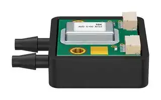
B58621V2894B767
Pressure Sensor, 7 bar, Digital (I2C), Differential, 5.5 V, Hose / Tube, 3 mA
⚠️ Reference pricing provided. In case of supply shortages, we will connect you with our trusted procurement partners to ensure your project's continuity.
- Manufacturer: EPCOS
- Product type: Pressure Transducers
- Port Style: Hose / Tube
- Product Range: AVD Series
- Sensor Output: Digital (I2C)
- Supply Current: 3mA
- Voltage Rating: 5.5V
- Operating Pressure Max: 7bar
- Pressure Measurement Type: Differential
| Delivery and price | |
|---|---|
| Units per pack | 10 |
| Price | 65.71 € |
| Current stock | 10+ |
| Lead time | 7 days |
Datasheet

## **Pressure sensors** ## Differential pressure transmitter with I²C output |**Series/Type:**|**AVD 7.000 KA D4 Z14E L ST B767**| |---|---| |**Ordering code:**|**B58621V2894B767**| |Date:|2021-07-26| |Version:|1.1| TDK Electronics AG 2021. Reproduction, publication and dissemination of this publication, enclosures hereto and the information contained therein without TDK Electronics' prior express consent is prohibited. ## ~~Lo~~ **Pressure sensors B58621V2894B767 Differential pressure transmitter with I²C output AVD 7.000 KA D4 Z14E L ST B767** ## **Applications** - Differential pressure measurement e.g. for flow control and filter monitoring in building measurement systems - Gauge pressure measurement e.g. for pressure level control and gas dosing in respirators ## **Features** - Pressure range 0 … 7 bar - Pressure signal accuracy typ. ± 0.35 % FS in a wide temperature range from -20 … +70 °C - Temperature signal accuracy typ. ± 2 K in a wide temperature range from -20 … +70 °C - Digital I²C output proportional to pressure: 10 ... 90% of digital output range (14 bit) - Piezoresistive MEMS technology - Measured media: air, non-aggressive gases - Prepared for screw mounting to provide improved mechanical stability - Pressure ports with hose connections for easy mounting of tubes - RoHS-compatible, halogen free according to IEC 61249-2-21 clause 3.1 ## **Dimensional drawings** Dimensions in mm TPS PRS T PD 2021-07-26 Page 2 of 10 Please read _Cautions and warnings_ and _Important notes_ at the end of this document. **Pressure sensors B58621V2894B767 Differential pressure transmitter with I²C output AVD 7.000 KA D4 Z14E L ST B767** ## **Technical data** ## **Absolute maximum ratings** |**Parameter**|**Symbol**|**Conditions**|**Min.**|**Typ.**|**Typ.**|**Max.**|**Unit**| |---|---|---|---|---|---|---|---| |**Temperature ranges**|||||||| |Storage temperature range<br>Tst<br>1)<br>–30<br>+70<br>°C<br>Operating temperature range<br>Ta<br>2)<br>–20<br>+70<br>°C<br>Compensated temperature range<br>Tc<br>3)<br>–20<br>+70<br>°C<br>~~————~~|||||||| |**Pressure ranges**|||||||| |Rated pressure range|pr|differential pressure4)|0|||7|bar| |Overpressure|pov|differential pressure4), 5)|-1|||14|bar| |Burst pressure|pburst|differential pressure4), 6)|-1|||14|bar| |Line burst pressure|pline|7)|0|||15|bar abs.| |**Supply voltage /-current**|||||||| |Supply voltage<br>VCC<br>8)<br>2.7<br>5.5<br>V<br>Supply current<br>ICC<br>9)<br>3<br>10<br>mA<br>~~EE~~|||||||| |**Output signal @ Ta = 25 °C, VCC = 5 V**|||||||| |Pressure output range<br>(pr,min..pr,max)|DA|10%...90% of 14 bit range|1637|||14745|digit| |Offset**IF)**|DA0|10)|||1637||digit| |Signal span (FullScale)|DFS|11)|||13107||digit| |Temperature output range<br>(-50…+150°C)|DT|full 11 Bit range|0|||2047|digit| |Offset error|E0LTS|12)|||0.1|0.5|% FS| |Nonlinearity|L|13)|||0.15|0.5|% FS| |Characteristic curve error|Ec|@ Ta= –20 ... 70 °C3), 14)|||0.25|0.5|% FS| |Total error (E0LTS+ Ec)|Etotal|@ Ta= –20 ... 70 °C3), 15)|||0.35|1|% FS| |Temperatur signal error|ET|@ Ta= –20 ... 70 °C|||2.0|3.0|K| |**Configuration, digital interface**|||||||| |System clock frequency||||4 MHz|4 MHz||| |Update period||||0.5 ms|||| |Communication type||||I²C|||| |I²C-address||||0 x 30|0 x 30||| |Sleep mode||||inactive|||| TPS PRS T PD 2021-07-26 Page 3 of 10 Please read _Cautions and warnings_ and _Important notes_ at the end of this document. ## ~~LT~~ **Pressure sensors B58621V2894B767 Differential pressure transmitter with I²C output AVD 7.000 KA D4 Z14E L ST B767** ## **I²C Read Operation** |**Anti-aliasing filter**||||||| |---|---|---|---|---|---|---| |Attenuation reference||3 Hz||0||dB| |Attenuation||30 Hz||81.5||dB| |Attenuation||200 Hz||328||dB| TPS PRS T PD 2021-07-26 Page 4 of 10 Please read _Cautions and warnings_ and _Important notes_ at the end of this document. ## **Pressure sensors B58621V2894B767 Differential pressure transmitter with I²C output AVD 7.000 KA D4 Z14E L ST B767** ## **Connection diagram** ## **Pressure calculation from digital output DA** 𝑝[𝑚𝑏𝑎𝑟] = ~~—~~[𝐷][𝐴][−𝐷][𝐴0] × 𝑝𝑟 𝐷𝐹𝑆 ## **Temperature calculation from digital output DT** 𝐷𝑇 𝑇[°𝐶] = × 200°𝐶−50°𝐶 2047 **Pressure output characteristics** ## **Temperature output characteristics** **Labeling** ## **Pressure port assignment** **==> picture [58 x 46] intentionally omitted <==** **----- Start of picture text -----**<br> 123456<br>**----- End of picture text -----**<br> AVD – Sensor type, product family 0.016 – Rated pressure range pr: 0… 16 mbar B765 – Sensor type specification number SN – Serial number of sensor **P1** – high pressure **P2** – low pressure pr = p1 – p2 TPS PRS T PD 2021-07-26 Page 5 of 10 Please read _Cautions and warnings_ and _Important notes_ at the end of this document. ~~LT~~ **Pressure sensors B58621V2894B767 Differential pressure transmitter with I²C output AVD 7.000 KA D4 Z14E L ST B767** ## **Installation of the sensor** For fixation of the pressure transmitter two screws M3 with washers should be used. Cross head, hexagon socket head or star head screws should be preferred instead of slotted head screws to avoid damages during the mounting process. Maximum of washer’s outer diameter is 7 mm. Maximum of screw’s mounting torque is limited by the sensor to 1.5 Nm. Pressure ports are designed for flexible tubes with inner diameter of 4 mm. The joint of tube and pressure port has to be tested in pressure and temperature range to avoid leakage. The electrical connector on the sensor is specified as JST SM05B-SRSS-GU-TB or equivalent. Matching SR / SZ connector sockets are JST 05SR-3S or JST A05R05SR30K203B or equivalent. ## **Materials exposed to the media to be measured** Materials exposed to measured media at high pressure port p1: gloptop material based on epoxy, silicone adhesive, glass, silicon, ENIG surface on PCB, PA66 + EPDM Materials exposed to measured media at low pressure port p2: gloptop material based on epoxy, silicone adhesive, silicone gel, glass, silicon, aluminium, nickel, ENIG surface on PCB, PA66 + EPDM ## **Media compatibility** All media which are compatible with the above mentioned materials like air and non-aggressive gases. Condensing or freezing liquids or residues thereof can affect the accuracy or even damage the sensor. Gas humidity shall be in range of 0 ... 100% r.h. at high pressure port p1and in range of 0 ... 85% r.h. at low pressure port p2 Further cautions and warnings for storage, mounting and operation on page 8. For fixation of the pressure transmitter two screws M3 with washers should be used. Cross head, hexagon socket head or star head screws should be preferred instead of slotted head screws to avoid damages during the mounting process. Maximum of washer’s out TPS PRS T PD Page 6 of 10 Please read _Cautions and warnings_ and _Important notes_ at the end of this document. ~~LT~~ **Pressure sensors B58621V2894B767 Differential pressure transmitter with I²C output AVD 7.000 KA D4 Z14E L ST B767** ## **Symbols and terms** ## **1) Storage temperature range Tst** A storage of the pressure sensor within the temperature range Tst,min up to Tst,max and without applied pressure and supply voltage will not affect the performance of the pressure sensor. ## **2) Operating temperature range Ta** An operation of the pressure sensor within the temperature range Ta,min up to Ta,max will not affect the performance of the pressure sensor. ## **3) Compensated temperature range Tc** While operating the pressure sensor within the temperature range Tc,min up to Tc,max, the deviation of the output signal from the values at 25 °C will not exceed the temperature coefficients. Out of the compensated temperature range, the deviations may increase. ## **4) Rated pressure pr** Within the rated pressure range pr,min up to pr,max the signal output characteristic corresponds to this specification. Rated pressure pr is calculated as difference between p1 and p2. (pr = p1 - p2). ## **5) Overpressure pOV** Pressure cycles within the pressure range 0 up to pov will not affect the performance of the pressure sensor. pov is calculated as difference between p1 and p2. (pr = p1 - p2). ## **6) Burst pressure pburst** Pressure cycles within the pressure range 0 up to pburst will not affect the hermeticety of the pressure sensor. Performance of the pressure sensor may be affected. pov is calculated as difference between p1 and p2. (pr = p1 - p2). ## **7) Line burst pressure pline** Pressure working symmetrically on both pressure ports. Pressure cycles within the range 0 up to pburst will not affect the hermeticety of the pressure sensor. Performance of the pressure sensor will not be affected irreversibly. High line pressure can cause high pressure peaks working on one side of the sensor and affecting the sensor. ## **8) Supply voltage VCC** VCC,max is the maximum permissible supply voltage, which can be applied without damages. VCC,min is the minimum required supply voltage, which has to be applied for normal operation. ## **9) Supply current ICC** ICC, is current consumption of the pressure sensor in operation. ## **10) Offset DA0** The offset DA0 is the digital signal output DA(p = 0). ## **11) Pressure output span (Full Scale)** DFS = FS = DA(pr,max) – DA(pr,min) ## **12) Offset error EA0** Deviation of the offset signal output DA(p = 0) to nominal value. ## **13) Non-linearity L (including pressure hysteresis)** The nonlinearity is the deviation of the real sensor characteristic DA = f(p) from the ideal straight line. It can be approximated by a polynomial of second order, with the maximum at px = pr / 2 . The equation to calculate the nonlinearity is: **==> picture [110 x 28] intentionally omitted <==** ## **14) Characteristic curve error EC** Within the compensated temperature range Tc,min up to Tc,max the error of characteristic curve Ec is the maximum deviation to the ideal characteristic curve, including non-linearity, calibration tolerances as well as temperature errors of offset and span. Out of the compensated temperature range, the deviations may increase. ## **15) Total error Etotal = E0LTS + EC** Sum of Offset error and characteristic curve error. The offset error EA0 is a parallel translation of the whole tolerance zone of the characteristic curve error. A periodic (to be defined by the user) offset correction at a defined pressure (e.g. zero) may considerably improve the measurement accuracy. TPS PRS T PD Page 7 of 10 Please read _Cautions and warnings_ and _Important notes_ at the end of this document. ~~LT~~ **Pressure sensors B58621V2894B767 Differential pressure transmitter with I²C output AVD 7.000 KA D4 Z14E L ST B767** ## **Cautions and warnings** ## **Storage** All pressure sensors should be stored in their original packaging. Maximum storage and time in original package is 2 years after the date of production. Transmitters should not be placed in harmful environments such as corrosive gases nor exposed to heat or direct sunlight, which may cause deformations. Similar effects may result from extreme storage temperatures and climatic conditions. Avoid storing the sensors in an environment where condensation may form or in a location exposed to corrosive gases, which will adversely affect their performance. ## **Mounting** Handle the fixation screws carefully during the mounting process to avoid damages of the sensor. Do not exceed the given mounting torque. Check length of screws for stable fixation. The joint of tubes and pressure ports has to be tested in pressure and temperature range to avoid leakage. Release all mounting processes carefully. ## **Operation (general)** Media compatibility with the pressure sensors has to be ensured to prevent failure. The use of other media can cause damage and malfunction. Never use pressure sensors in atmospheres containing explosive liquids or gases. Ensure pressure equalization to the environment, if gauge pressure sensors are used. Avoid operating the pressure sensors in an environment where condensation may form or in a location exposed to corrosive gases. These environments adversely affect their performance. If the operating pressure is not within the rated pressure range, it may change the output characteristics. This may also happen with pressure sensor dies if an incorrect mounting method is used. Be sure that the applicable pressure does not exceed the over pressure, as it may damage the pressure sensor. Do not exceed the maximum rated supply voltage nor the rated storage temperature range, as it may damage the pressure sensor. Temperature variations in both the ambient conditions and the media (liquid or gas) can affect the accuracy of the output signal from the pressure sensors. Be sure to check the operating temperature range and thermal error specification of the pressure sensors to determine their suitability for the application. Connections must be wired in accordance with the terminal assignment specified in the data sheets. Care should be taken as reversed pin connections can damage the pressure transmitters or degrade their performance. Contact between the pressure sensor terminals and metals or other materials may cause errors in the output characteristics. Re-programming of sensor’s signal conditioner can effect accuracy of measurements and function of interface. TDK reserves the right to end all warranties of the sensor if interventions in sensors programming were made. This listing does not claim to be complete, but merely reflects the experience of TDK Electronics AG. ## **Display of ordering codes for TDK Electronics products** The ordering code for one and the same product can be represented differently in data sheets, data books, other publications, on the company website, or in order-related documents such as shipping notes, order confirmations and product labels. **The varying representations of the ordering codes are due to different processes employed and do not affect the specifications of the respective products** . Detailed information can be found on the Internet under www.tdk-electronics.tdk.com/orderingcodes. TPS PRS T PD Page 8 of 10 Please read _Cautions and warnings_ and _Important notes_ at the end of this document. ~~LT~~ **Important notes** The following applies to all products named in this publication: 1. Some parts of this publication contain **statements about the suitability of our products for certain areas of application** . These statements are based on our knowledge of typical requirements that are often placed on our products in the areas of application concerned. We nevertheless expressly point out **that such statements cannot be regarded as binding statements about the suitability of our products for a particular customer application.** As a rule we are either unfamiliar with individual customer applications or less familiar with them than the customers themselves. For these reasons, it is always ultimately incumbent on the customer to check and decide whether a product with the properties described in the product specification is suitable for use in a particular customer application. 2. We also point out that **in individual cases, a malfunction of electronic components or failure before the end of their usual service life cannot be completely ruled out in the current state of the art, even if they are operated as specified.** In customer applications requiring a very high level of operational safety and especially in customer applications in which the malfunction or failure of an electronic component could endanger human life or health (e.g. in accident prevention or lifesaving systems), it must therefore be ensured by means of suitable design of the customer application or other action taken by the customer (e.g. installation of protective circuitry or redundancy) that no injury or damage is sustained by third parties in the event of malfunction or failure of an electronic component. 3. **The warnings, cautions and product-specific notes must be observed.** 4. In order to satisfy certain technical requirements, **some of the products described in this publication may contain substances subject to restrictions in certain jurisdictions (e.g. because they are classed as hazardous)** . Useful information on this will be found in our Material Data Sheets on the Internet (www.tdk-electronics.tdk.com/material). Should you have any more detailed questions, please contact our sales offices. 5. We constantly strive to improve our products. Consequently, **the products described in this publication may change from time to time** . The same is true of the corresponding product specifications. Please check therefore to what extent product descriptions and specifications contained in this publication are still applicable before or when you place an order. We also **reserve the right to discontinue production and delivery of products** . Consequently, we cannot guarantee that all products named in this publication will always be available. The aforementioned does not apply in the case of individual agreements deviating from the foregoing for customer-specific products. 6. Unless otherwise agreed in individual contracts, **all orders are subject to our General Terms and Conditions of Supply.** 7. **Our manufacturing sites serving the automotive business apply the IATF 16949 standard.** The IATF certifications confirm our compliance with requirements regarding the quality management system in the automotive industry. Referring to customer requirements and customer specific requirements (“CSR”) TDK always has and will continue to have the policy of respecting individual agreements. Even if IATF 16949 may appear to support the acceptance of unilateral requirements, we hereby like to emphasize that **only requirements mutually agreed upon can and will be implemented in our Quality Management System.** For clarification purposes we like to point out that obligations from IATF 16949 shall only become legally binding if individually agreed upon. Page 9 of 10 ## ~~LT~~ **Important notes** 8. The trade names EPCOS, CarXield, CeraCharge, CeraDiode, CeraLink, CeraPad, CeraPlas, CSMP, CTVS, DeltaCap, DigiSiMic, ExoCore, FilterCap, FormFit, LeaXield, MiniBlue, MiniCell, MKD, MKK, ModCap, MotorCap, PCC, PhaseCap, PhaseCube, PhaseMod, PhiCap, PowerHap, PQSine, PQvar, SIFERRIT, SIFI, SIKOREL, SilverCap, SIMDAD, SiMic, SIMID, SineFormer, SIOV, ThermoFuse, WindCap, XieldCap are **trademarks registered or pending** in Europe and in other countries. Further information will be found on the Internet at www.tdk-electronics.tdk.com/trademarks. ## Release 2020-06 Page 10 of 10
Updated at February 9, 2023
About Novapart
Novapart is a B2B electronic component broker specialising in stock shortages and cost reduction. We source hard-to-find parts and identify compliant alternatives across a catalogue of 410,000+ components from 500+ manufacturers.
Learn more →Stock Shortage Specialist
When a component is unavailable, discontinued or has an unacceptable lead time, we tap into our network of vetted European and Asian distributors to source what you need — without compromising on quality or traceability.
Request a quote →Compliant Alternatives
We identify pin-to-pin, electrically equivalent substitutes that meet the same certifications (RoHS, AEC-Q100, REACH) as your original specification — validated against datasheets, not just part numbers. Often at a lower cost.
BOM Analysis service →