
Image not available
Illustrative purposes only

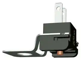
B58100A0461A000
Thermistor, NTC, 10.151 kohm, B58100 Series, 4005 K, Panel, Quick Connect
⚠️ Reference pricing provided. In case of supply shortages, we will connect you with our trusted procurement partners to ensure your project's continuity.
- Manufacturer: EPCOS
- Product type: Temperature Sensing / Compensation NTC Thermistors
- Product Range: B58100
- Beta Value (K): 4005K
- Thermistor Mounting: Panel
- Thermistor Terminals: Quick Connect
- Operating Temperature Max: 100°C
- Operating Temperature Min: -5°C
- Zero Power Resistance at 25°C: 10.151kohm
| Delivery and price | |
|---|---|
| Units per pack | 5000 |
| Price | 4.08 € |
| Current stock | 10+ |
| Lead time | 30 days |
Datasheet

## **NTC thermistors for temperature measurement**

Probe assemblies, surface mounted sensors

**Series/Type: B58100** Date: April 2013

© EPCOS AG 2015. Reproduction, publication and dissemination of this publication, enclosures hereto and the information contained therein without EPCOS' prior express consent is prohibited.

EPCOS AG is a TDK Group Company.

**Temperature measurement B58100 Probe assemblies F120**

## **Applications**

## **Dimensional drawing**

- Surface mounted sensor for measurement of boiler temperature

## **Features**

Short response time due to

glass-encapsulated NTC thermistor Fast and easy mounting

- Screw attachment fixation

## **Options**

- r Alternative resistance ratings available on | request

- Alternative fast-on plug terminals 2.8 x 0.5 or 4.8 x 0.8 mm available

## **Delivery mode**

Bulk

Dimensions in mm

## **General technical data**

|Climatic category<br>(IEC 60068-1)<br>Maximum power<br>(at 25°C)<br>P<br>Resistance tolerance<br>∆<br>Rated temperature<br>T<br>Thermal time constant<br>(measured on surface)<br>τ<br>Insulation resistance<br>(V = 100 V DC, t = 1 min)<br>R<br>Dissipation factor<br>(in air)<br>δ<br>Test voltage<br>(t = 1 s)<br>V|5/100/21<br>P25<br>18<br>∆RR/RR<br>±<br>TR<br>60<br>τa<br>< 5<br>Rins<br>> 10<br>δth<br>approx. 2.1<br>Vtest<br>500|5/100/21<br>18<br>±3.6<br>60<br>< 5<br>> 10<br>approx. 2.1<br>500|mW<br>%<br>°C<br>s<br>MΩ<br>mW/K<br>V AC|
|---|---|---|---|


## **Electrical specification and ordering codes**

|R60<br>Ω|R25<br>Ω|No. of<br>R/T characteristic|B25/100<br>K|B0/100<br>K|Contact<br>dimensions<br>mm|Ordering code|
|---|---|---|---|---|---|---|
|2500<br>2500|10151<br>10151|8317<br>8317|4005±1%<br>4005±1%|3970<br>3970|2.8 x 0.5<br>4.8 x 0.8|B58100A0461A000<br>B58100A0463A000|


Please read _Cautions and warnings_ and _Important notes_ at the end of this document.

Page 2 of 9

## ~~Lt~~ **Temperature measurement B58100 Probe assemblies F120**

## **Reliability data**

|Standard|Test conditions|∆R100/R100<br>(typical)|
|---|---|---|
|IEC<br>60068-2-2|Storage at upper<br>category temperature<br>T: 100°C<br>t: 500 h|< 3%|
|IEC<br>60068-2-78|Temperature of air: 85°C<br>Relative humidity of air: 85%<br>Duration: 21 days|< 5%|
|IEC<br>60068-2-14|Lower test temperature: 5°C<br>Upper test temperature: 85°C<br>Number of cycles: 1000|< 3%|
||Short time overload: 125°C<br>t: 10 h|< 3%|


## **Note**

Contact of NTC thermistors with any liquids and solvents shall be prevented. It must be ensured that no water enters the NTC thermistors (e.g. through plug terminals). Avoid dewing and condensation unless thermistor is specified for these conditions.

Please read _Cautions and warnings_ and _Important notes_ at the end of this document.

Page 3 of 9

~~Lt~~ **Temperature measurement B58100 Probe assemblies F120**

## **R/T characteristics**

|**8317**|**8317**||||||
|---|---|---|---|---|---|---|
|B25/100= 4005 K||T (°C)|B25/100= 4005 K||T (°C)||
|RT/R25|α (%/K)||RT/R25|α (%/K)||RT/R25|
|99.49<br>69.168<br>48.679<br>34.662<br>24.959<br>18.166<br>13.358<br>9.9201<br>7.4369<br>5.6261<br>4.2935|7.4<br>7.2<br>6.9<br>6.7<br>6.5<br>6.3<br>6.1<br>5.9<br>5.7<br>5.5<br>5.3|0.0<br>5.0<br>10.0<br>15.0<br>20.0<br>25.0<br>30.0<br>35.0<br>40.0<br>45.0<br>50.0|3.304<br>2.5632<br>2.0038<br>1.5783<br>1.252<br>1.0000<br>0.80403<br>0.6506<br>0.52967<br>0.43377<br>0.35726|5.2<br>5.0<br>4.9<br>4.7<br>4.6<br>4.4<br>4.3<br>4.2<br>4.1<br>3.9<br>3.8|55.0<br>60.0<br>65.0<br>70.0<br>75.0<br>80.0<br>85.0<br>90.0<br>95.0<br>100.0|0.29585<br>0.24629<br>0.20608<br>0.17327<br>0.14638<br>0.12422<br>0.10588<br>0.090628<br>0.07789<br>0.067207|


Please read _Cautions and warnings_ and _Important notes_ at the end of this document.

Page 4 of 9

~~Lt~~ **Temperature measurement B58100 Probe assemblies F120**

## **Cautions and warnings**

See "Important notes".

## **Storage**

- Store thermistors only in original packaging. Do not open the package prior to storage. Storage conditions in original packaging: storage temperature 25 °C ... +45 °C, relative humidity ≤75% annual mean, <95% maximum 30 days per annum, dew precipitation is inadmissible.

- Do not store thermistors where they are exposed to heat or direct sunlight. Otherwise, the packing material may be deformed or components may stick together, causing problems during mounting.

- Avoid contamination of thermistor surface during storage, handling and processing. Avoid storage of thermistors in harmful environments like corrosive gases (SOx, Cl etc). Use the components as soon as possible after opening the factory seals, i.e. the polyvinyl-sealed packages.

- Solder thermistors within the time specified after shipment from EPCOS.

- For leaded components this is 24 months, for SMD components with nickel barrier termination 12 months, for SMD components with AgPd termination 6 months.

## **Handling**

- NTC thermistors must not be dropped. Chip-offs or any other damage must not be caused during handling of NTCs.

- Do not touch components with bare hands. Gloves are recommended. Avoid contamination of thermistor surface during handling.

- Washing processes may damage the product due to the possible static or cyclic mechanical loads (e.g. ultrasonic cleaning). They may cause cracks to develop on the product and its parts, which might lead to reduced reliability or lifetime.

## **Bending / twisting leads**

- A lead (wire) may be bent at a minimum distance of twice the wire’s diameter plus 4 mm from the component head or housing. When bending ensure the wire is mechanically relieved at the component head or housing. The bending radius should be at least 0.75 mm. Twisting (torsion) by 180° of a lead bent by 90° is permissible at 6 mm from the bottom of the thermistor body.

## **Soldering**

- Use resin-type flux or non-activated flux.

Insufficient preheating may cause ceramic cracks.

- Rapid cooling by dipping in solvent is not recommended. Complete removal of flux is recommended.

Please read _Cautions and warnings_ and _Important notes_ at the end of this document.

Page 5 of 9

~~Lt~~ **Temperature measurement B58100 Probe assemblies F120**

## **Mounting**

- Ensure that no thermo-mechanical stress occurs due to production processes (curing or overmolding processes) when thermistors are sealed, potted or overmolded or during their subsequent operation. The maximum temperature of the thermistor must not be exceeded. Ensure that the materials used (sealing/potting compound and plastic material) are chemically neutral.

- Electrodes/contacts must not be scratched or damaged before/during/after the mounting process.

- Contacts and housing used for assembly with the thermistor must be clean before mounting. Ensure that adjacent materials are designed for operation at temperatures comparable to the surface temperature of the thermistor. Be sure that surrounding parts and materials can withstand the temperature.

- Avoid contamination of the thermistor surface during processing.

- The connections of sensors (e.g. cable end, wire end, plug terminal) may only be exposed to an environment with normal atmospheric conditions.

- Tensile forces on cables or leads must be avoided during mounting and operation. Bending or twisting of cables or leads directly on the thermistor body is not permissible. Avoid using chemical substances as mounting aids. It must be ensured that no water or other liquids enter the NTC thermistors (e.g. through plug terminals). In particular, water based substances (e.g. soap suds) must not be used as mounting aids for sensors.

## **Operation**

Use thermistors only within the specified operating temperature range.

- Use thermistors only within the specified power range.

- Environmental conditions must not harm the thermistors. Only use the thermistors under normal atmospheric conditions or within the specified conditions.

- Contact of NTC thermistors with any liquids and solvents shall be prevented. It must be ensured that no water enters the NTC thermistors (e.g. through plug terminals). For measurement purposes (checking the specified resistance vs. temperature), the component must not be immersed in water but in suitable liquids (e.g. Galden).

- Avoid dewing and condensation unless thermistor is specified for these conditions.

- Bending or twisting of cables and/or wires is not permissible during operation of the sensor in the application.

- Be sure to provide an appropriate fail-safe function to prevent secondary product damage caused by malfunction.

This listing does not claim to be complete, but merely reflects the experience of EPCOS AG.

Please read _Cautions and warnings_ and _Important notes_ at the end of this document.

Page 6 of 9

~~Lt~~ **Temperature measurement B58100 Probe assemblies F120**

## **Symbols and terms**

|Symbol|English|German|
|---|---|---|
|A<br>AWG<br>B<br>B25/100<br>Cth<br>I<br>N<br>P25<br>Pdiss<br>Pel<br>Pmax<br>∆RB/RB<br>Rins<br>RP<br>RR<br>∆RR/RR<br>RS<br>RT<br>T<br>∆T<br>t<br>TA<br>Tmax<br>Tmin<br>Top<br>TR<br>Tsurf<br>V<br>Vins<br>Vop<br>Vtest|Area<br>American Wire Gauge<br>B value<br>B value determined by resistance<br>measurement at 25°C and 100°C<br>Heat capacitance<br>Current<br>Number (integer)<br>Maximum power at 25°C<br>Power dissipation<br>Electrical power<br>Maximum power within stated<br>temperature range<br>Resistance tolerance caused by<br>spread of B value<br>Insulation resistance<br>Parallel resistance<br>Rated resistance<br>Resistance tolerance<br>Series resistance<br>Resistance at temperature T<br>(e.g. R25= resistance at 25°C)<br>Temperature<br>Temperature tolerance<br>Time<br>Ambient temperature<br>Upper category temperature<br>Lower category temperature<br>Operating temperature<br>Rated temperature<br>Surface temperature<br>Voltage<br>Insulation test voltage<br>Operating voltage<br>Test voltage|Fläche<br>Amerikanische Norm für Drahtquerschnitte<br>B-Wert<br>B-Wert, ermittelt durch Widerstands-<br>messungen bei 25°C und 100°C<br>Wärmekapazität<br>Strom<br>Anzahl (ganzzahliger Wert)<br>Maximale Leistung bei 25°C<br>Verlustleistung<br>Elektrische Leistung<br>Maximale Leistung im<br>angegebenenTemperaturbereich<br>Widerstandstoleranz, die durch die<br>Streuung des B-Wertes verursacht wird<br>Isolationswiderstand<br>Parallelwiderstand<br>Nennwiderstand<br>Widerstandstoleranz<br>Serienwiderstand<br>Widerstand bei Temperatur T<br>(z.B. R25= Widerstand bei 25°C)<br>Temperatur<br>Temperaturtoleranz<br>Zeit<br>Umgebungstemperatur<br>Obere Grenztemperatur<br>(Kategorietemperatur)<br>Untere Grenztemperatur<br>(Kategorietemperatur)<br>Betriebstemperatur<br>Nenntemperatur<br>Oberflächentemperatur<br>Spannung<br>Isolationsprüfspannung<br>Betriebsspannung<br>Prüfspannung|


Please read _Cautions and warnings_ and _Important notes_ at the end of this document.

Page 7 of 9

## ~~Lt~~ **Temperature measurement B58100 Probe assemblies F120**

|Symbol|English|German|
|---|---|---|
|α|Temperature coefficient|Temperaturkoeffizient|
|∆|Tolerance, change|Toleranz, Änderung|
|δth|Dissipation factor|Wärmeleitwert|
|τc|Thermal cooling time constant|Thermische Abkühlzeitkonstante|
|τa|Thermal time constant|Thermische Zeitkonstante|
|**Abbreviations / Notes**|||
|Symbol<br>English<br>German<br>Surface-mounted devices<br>Oberflächenmontierbares Bauelement<br>*<br>To be replaced by a number in ordering<br>codes, type designations etc.<br>Platzhalter für Zahl im Bestellnummern-<br>code oder für die Typenbezeichnung.<br>+<br>To be replaced by a letter.<br>Platzhalter für einen Buchstaben.<br>All dimensions are given in mm.<br>Alle Maße sind in mm angegeben.<br>The commas used in numerical values<br>denote decimalpoints.<br>Verwendete Kommas in Zahlenwerten<br>bezeichnen Dezimalpunkte.<br>~~“||.~~|||


Please read _Cautions and warnings_ and _Important notes_ at the end of this document.

Page 8 of 9

~~Lt~~ **Important notes**

The following applies to all products named in this publication:

1. Some parts of this publication contain **statements about the suitability of our products for certain areas of application** . These statements are based on our knowledge of typical requirements that are often placed on our products in the areas of application concerned. We nevertheless expressly point out **that such statements cannot be regarded as binding statements about the suitability of our products for a particular customer application** . As a rule, EPCOS is either unfamiliar with individual customer applications or less familiar with them than the customers themselves. For these reasons, it is always ultimately incumbent on the customer to check and decide whether an EPCOS product with the properties described in the product specification is suitable for use in a particular customer application.

2. We also point out that **in individual cases, a malfunction of electronic components or failure before the end of their usual service life cannot be completely ruled out in the current state of the art, even if they are operated as specified** . In customer applications requiring a very high level of operational safety and especially in customer applications in which the malfunction or failure of an electronic component could endanger human life or health (e.g. in accident prevention or lifesaving systems), it must therefore be ensured by means of suitable design of the customer application or other action taken by the customer (e.g. installation of protective circuitry or redundancy) that no injury or damage is sustained by third parties in the event of malfunction or failure of an electronic component.

3. **The warnings, cautions and product-specific notes must be observed.**

4. In order to satisfy certain technical requirements, **some of the products described in this publication may contain substances subject to restrictions in certain jurisdictions (e.g. because they are classed as hazardous)** . Useful information on this will be found in our Material Data Sheets on the Internet (www.epcos.com/material). Should you have any more detailed questions, please contact our sales offices.

5. We constantly strive to improve our products. Consequently, **the products described in this publication may change from time to time** . The same is true of the corresponding product specifications. Please check therefore to what extent product descriptions and specifications contained in this publication are still applicable before or when you place an order. We also **reserve the right to discontinue production and delivery of products** . Consequently, we cannot guarantee that all products named in this publication will always be available. The aforementioned does not apply in the case of individual agreements deviating from the foregoing for customer-specific products.

6. Unless otherwise agreed in individual contracts, **all orders are subject to the current version of the "General Terms of Delivery for Products and Services in the Electrical Industry" published by the German Electrical and Electronics Industry Association (ZVEI)** .

7. The trade names EPCOS, BAOKE, Alu-X, CeraDiode, CeraLink, CSMP, CSSP, CTVS, DeltaCap, DigiSiMic, DSSP, FilterCap, FormFit, MiniBlue, MiniCell, MKD, MKK, MLSC, MotorCap, PCC, PhaseCap, PhaseCube, PhaseMod, PhiCap, SIFERRIT, SIFI, SIKOREL, SilverCap, SIMDAD, SiMic, SIMID, SineFormer, SIOV, SIP5D, SIP5K, ThermoFuse, WindCap are **trademarks registered or pending** in Europe and in other countries. Further information will be found on the Internet at www.epcos.com/trademarks.

Page 9 of 9
Updated at February 9, 2023
About Novapart
Novapart is a B2B electronic component broker specialising in stock shortages and cost reduction. We source hard-to-find parts and identify compliant alternatives across a catalogue of 410,000+ components from 500+ manufacturers.
Learn more →Stock Shortage Specialist
When a component is unavailable, discontinued or has an unacceptable lead time, we tap into our network of vetted European and Asian distributors to source what you need — without compromising on quality or traceability.
Request a quote →Compliant Alternatives
We identify pin-to-pin, electrically equivalent substitutes that meet the same certifications (RoHS, AEC-Q100, REACH) as your original specification — validated against datasheets, not just part numbers. Often at a lower cost.
BOM Analysis service →