
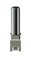


B57276K0123A024
NTC Thermistor, 11.981 kohm, Quick Connect, 3760 K
- Manufacturer: TDK
- Product type:
- SVHC: Lead (25-Jun-2025)
- B-Constant: 3760K
- Lead Length: -
- NTC Mounting: Panel Mount
- NTC Case Size: -
- Product Range: B57276K Series
- Qualification: -
- Probe Diameter: 10mm
- Probe Material: Stainless Steel
- Thermistor Type: Probe
- Resistance (25°C): 11.981kohm
- Thermistor Mounting: Panel
- B-Constant Tolerance: ± 1.5%
- Thermistor Terminals: Quick Connect
- Operating Temperature Max: 100°C
- Operating Temperature Min: -10°C
- Resistance Tolerance (25°C): ± 2%
- Thermal Time Constant (in Air): 20s
| Delivery and price | |
|---|---|
| Units per pack | 1600 |
| Price | 3.87 € |
| Current stock | 200+ |
| Lead time | 30 days |
**==> picture [131 x 50] intentionally omitted <==**

## **NTC thermistors for temperature measurement**

Probe assemblies

**Series/Type: B57276K** Date: January 2018

© EPCOS AG 2018. Reproduction, publication and dissemination of this publication, enclosures hereto and the information contained therein without EPCOS' prior express consent is prohibited.

EPCOS AG is a TDK Group Company.

|**Temperature measurement**|**B57276K**|
|---|---|
|**Probe assemblies**|**K276**|


## **Applications**

**==> picture [5 x 5] intentionally omitted <==**

**==> picture [5 x 5] intentionally omitted <==**

**==> picture [5 x 5] intentionally omitted <==**

**==> picture [5 x 5] intentionally omitted <==**

- Washing machines Dish washers Tumble-dryers Water boilers

## **Features**

**==> picture [5 x 5] intentionally omitted <==**

**==> picture [5 x 5] intentionally omitted <==**

**==> picture [5 x 5] intentionally omitted <==**

**==> picture [5 x 5] intentionally omitted <==**

**==> picture [5 x 5] intentionally omitted <==**

**==> picture [5 x 5] intentionally omitted <==**

Suitable for use in corrosive environments

- Compact stainless steel case

- RAST 2.5 or RAST 5 connector

- Cost-effective ready-to-use sensor UL approval (E69802)

- VDE approval (DIN EN 60539-1: 2002)

## **Options**

**==> picture [5 x 5] intentionally omitted <==**

**==> picture [5 x 5] intentionally omitted <==**

**==> picture [5 x 5] intentionally omitted <==**

- Alternative resistance ratings, rated temperatures and resistance tolerances available on request.

- RAST 5 plug terminals or RAST 2.5 connector with bar available on request.

- Type Z276, Z277 and Z278 with different geometry and faster response time available on request.

## **Delivery mode**

Bulk

## **Dimensional drawings**

**==> picture [40 x 55] intentionally omitted <==**

## Dimensions

|R60<br>Ω<br>A max.<br>mm|R60<br>Ω<br>A max.<br>mm|Plug terminal<br>mm|
|---|---|---|
|RAST 2.5 connector<br>1204<br>∅14.5<br>3243<br>∅12.4||-<br>-|
|RAST 5 connector|||
|1082<br>3243|∅14.5<br>∅12.4|6.3 x 0.8<br>4.8 x 0.8|


Approx. weight 9 g

Approx. weight 9 g

Please read _Cautions and warnings_ and _Important notes_ at the end of this document.

Page 2 of 13

|**Temperature measurement**|**B57276K**|
|---|---|
|**Probe assemblies**|**K276**|


## **General technical data**

|Climatic category<br>(IEC 60068-1)<br>Max. power<br>(at 25°C)<br>Resistance tolerance<br>Dissipation factor<br>(in water)<br>Thermal time constant<br>(in water)<br>Heat capacity<br>Insulation resistance<br>(V = 100 V DC)<br>Test voltage<br>(t = 1 s)|P25<br>∆RR/RR<br>δth<br>τa<br>Cth<br>Rins<br>Vtest|10/100/56<br>500<br>±2<br>approx. 20<br>approx. 20<br>approx. 500<br>> 1000<br>3750|mW<br>%<br>mW/K<br>s<br>mJ/K<br>MΩ<br>V AC|
|---|---|---|---|


## **Electrical specification and ordering codes**

|TR<br>°C|RR<br>Ω|R25<br>Ω|No. of R/T<br>characteristic|B25/100<br>K|Ordering code|
|---|---|---|---|---|---|
|RAST 2.5 connector||||||
|60<br>60|1204<br>3243|4829<br>11981|2003<br>2901|3980±1%<br>3760±1.5%|B57276K0482A007<br>B57276K0123A028|
|RAST 5 connector||||||
|63<br>60|1082<br>3243|4829<br>11981|2003<br>2901|3980±1.5%<br>3760±1.5%|B57276K0482A009<br>B57276K0123A024|


Please read _Cautions and warnings_ and _Important notes_ at the end of this document.

Page 3 of 13

|**Temperature measurement**|**B57276K**|
|---|---|
|**Probe assemblies**|**K276**|


## **Reliability data**

|**Reliability data**|||||
|---|---|---|---|---|
|Test|Standard|Test conditions|∆R25/R25<br>(typical)|Remarks|
|Storage in<br>dry heat|IEC<br>60068-2-2|Storage at upper<br>category temperature<br>T: 100°C<br>t: 1000 h|< 2%|No visible<br>damage|
|Storage in damp<br>heat, steady state|IEC<br>60068-2-78|Temperature of air: 40°C<br>Relative humidity of air: 93%<br>Duration: 56 days|< 1%|No visible<br>damage|
|Rapid temperature<br>cycling|IEC<br>60068-2-14|Lower test temperature:�10°C<br>Upper test temperature: 100°C<br>Number of cycles: 10|< 1%|No visible<br>damage|
|Endurance||Pmax: 500 mW<br>t: 1000 h|< 2%|No visible<br>damage|
|Long-term stability<br>(empirical value)||Temperature: 100°C<br>t: 10000 h|< 3%|No visible<br>damage|
|Robustness of<br>terminations|DIN<br>46 249|Pull-out force<br>(both connectors together)<br>F = 50 N||No visible<br>damage|


## **Note**

**==> picture [5 x 5] intentionally omitted <==**

**==> picture [5 x 5] intentionally omitted <==**

Contact of NTC thermistors with any liquids and solvents shall be prevented. It must be ensured that no water enters the NTC thermistors (e.g. through plug terminals). Avoid dewing and condensation unless thermistor is specified for these conditions.

Please read _Cautions and warnings_ and _Important notes_ at the end of this document.

Page 4 of 13

**Temperature measurement B57276K Probe assemblies K276**

## **R/T characteristics**

|R/T No.|**2003**|**2003**|**2901**|**2901**|
|---|---|---|---|---|
|T (°C)|B25/100= 3980 K||B25/100= 3760 K||
||RT/R25|α (%/K)|RT/R25|α (%/K)|
|�55.0<br>�50.0<br>�45.0<br>�40.0<br>�35.0<br>�30.0<br>�25.0<br>�20.0<br>�15.0<br>�10.0<br>�5.0<br>0.0<br>5.0<br>10.0<br>15.0<br>20.0<br>25.0<br>30.0<br>35.0<br>40.0<br>45.0<br>50.0<br>55.0<br>60.0<br>65.0<br>70.0<br>75.0<br>80.0<br>85.0<br>90.0<br>95.0<br>100.0<br>105.0<br>110.0<br>115.0<br>120.0<br>125.0<br>130.0<br>135.0<br>140.0<br>145.0<br>150.0<br>155.0|97.578<br>67.65<br>47.538<br>33.831<br>24.359<br>17.753<br>13.067<br>9.7228<br>7.3006<br>5.5361<br>4.2332<br>3.266<br>2.5392<br>1.9902<br>1.5709<br>1.2492<br>1.0000<br>0.80575<br>0.65326<br>0.5329<br>0.43715<br>0.36064<br>0.29908<br>0.24932<br>0.20886<br>0.17578<br>0.14863<br>0.12621<br>0.10763<br>0.092159<br>0.079225<br>0.068356<br>0.059247<br>0.051531<br>0.044921<br>0.039282<br>0.034387<br>0.030186<br>0.02665<br>0.023594<br>0.020931<br>0.018616<br>0.016612|7.5<br>7.2<br>7.0<br>6.7<br>6.5<br>6.3<br>6.0<br>5.8<br>5.6<br>5.5<br>5.3<br>5.1<br>5.0<br>4.8<br>4.7<br>4.5<br>4.4<br>4.3<br>4.1<br>4.0<br>3.9<br>3.8<br>3.7<br>3.6<br>3.5<br>3.4<br>3.3<br>3.2<br>3.1<br>3.1<br>3.0<br>2.9<br>2.8<br>2.8<br>2.7<br>2.7<br>2.6<br>2.5<br>2.5<br>2.4<br>2.4<br>2.3<br>2.3|63.969<br>46.179<br>33.738<br>24.927<br>18.611<br>14.033<br>10.679<br>8.198<br>6.3123<br>4.9014<br>3.821<br>3.0027<br>2.3801<br>1.9<br>1.5257<br>1.233<br>1.0000<br>0.81679<br>0.67166<br>0.55527<br>0.46095<br>0.38459<br>0.32184<br>0.27068<br>0.22907<br>0.19468<br>0.16607<br>0.14221<br>0.12218<br>0.10533<br>0.09123<br>0.079284<br>0.069062<br>0.06034<br>0.052886<br>0.046482<br>0.040985<br>0.036233<br>0.032101<br>0.02851<br>0.025373<br>0.022633<br>0.020231|6.7<br>6.4<br>6.2<br>6.0<br>5.8<br>5.6<br>5.4<br>5.3<br>5.2<br>5.1<br>4.9<br>4.7<br>4.6<br>4.5<br>4.3<br>4.3<br>4.1<br>4.0<br>3.9<br>3.8<br>3.8<br>3.7<br>3.6<br>3.5<br>3.3<br>3.2<br>3.1<br>3.1<br>3.0<br>2.9<br>2.8<br>2.8<br>2.7<br>2.7<br>2.6<br>2.5<br>2.5<br>2.5<br>2.4<br>2.4<br>2.3<br>2.3<br>2.3|


Please read _Cautions and warnings_ and _Important notes_ at the end of this document.

Page 5 of 13

|**Temperature measurement**|**B57276K**|
|---|---|
|**Probe assemblies**|**K276**|


Please read _Cautions and warnings_ and _Important notes_ at the end of this document.

Page 6 of 13

|**Temperature measurement**|**B57276K**|
|---|---|
|**Probe assemblies**|**K276**|


## **Cautions and warnings**

## **General**

See "Important notes" on page 2.

## **Storage**

**==> picture [5 x 5] intentionally omitted <==**

**==> picture [5 x 5] intentionally omitted <==**

**==> picture [5 x 5] intentionally omitted <==**

**==> picture [5 x 5] intentionally omitted <==**

**==> picture [5 x 5] intentionally omitted <==**

**==> picture [5 x 5] intentionally omitted <==**

**==> picture [5 x 5] intentionally omitted <==**

- Store thermistors only in original packaging. Do not open the package prior to processing. Storage conditions in original packaging: storage temperature �25 °C ... +45 °C, relative humidity ≤75% annual mean, <95% maximum 30 days per annum, dew precipitation is inadmissible.

- Do not store thermistors where they are exposed to heat or direct sunlight. Otherwise, the packing material may be deformed or components may stick together, causing problems during mounting.

- Avoid contamination of thermistor surface during storage, handling and processing. Avoid storage of thermistors in harmful environments like corrosive gases (SOx, Cl etc). Use the components as soon as possible after opening the original packaging. Solder thermistors within the time specified after shipment from EPCOS.

- For leaded components this is 24 months, for SMD components with nickel barrier termination 12 months, for leadless components this is 12 months, for SMD components with AgPd termination 6 months.

## **Handling**

**==> picture [5 x 5] intentionally omitted <==**

**==> picture [5 x 5] intentionally omitted <==**

**==> picture [5 x 5] intentionally omitted <==**

**==> picture [5 x 5] intentionally omitted <==**

- NTC thermistors must not be dropped. Chip-offs or any other damage must not be caused during handling of NTCs.

- Do not touch components with bare hands. Gloves are recommended. Avoid contamination of thermistor surface during handling.

- Washing processes may damage the product due to the possible static or cyclic mechanical loads (e.g. ultrasonic cleaning). They may cause cracks to develop on the product and its parts, which might lead to reduced reliability or lifetime.

## **Bending / twisting leads**

**==> picture [5 x 5] intentionally omitted <==**

- A lead (wire) may be bent at a minimum distance of twice the wire’s diameter plus 4 mm from the component head or housing. When bending ensure the wire is mechanically relieved at the component head or housing. The bending radius should be at least 0.75 mm.

## **Soldering**

**==> picture [5 x 5] intentionally omitted <==**

**==> picture [5 x 5] intentionally omitted <==**

**==> picture [5 x 5] intentionally omitted <==**

**==> picture [5 x 5] intentionally omitted <==**

- Use resin-type flux or non-activated flux.

Insufficient preheating may cause ceramic cracks.

- Rapid cooling by dipping in solvent is not recommended. Complete removal of flux is recommended.

Please read _Cautions and warnings_ and _Important notes_ at the end of this document.

Page 7 of 13

|**Temperature measurement**|**B57276K**|
|---|---|
|**Probe assemblies**|**K276**|


## **Mounting**

**==> picture [5 x 5] intentionally omitted <==**

**==> picture [5 x 5] intentionally omitted <==**

**==> picture [5 x 5] intentionally omitted <==**

**==> picture [5 x 5] intentionally omitted <==**

**==> picture [5 x 5] intentionally omitted <==**

**==> picture [5 x 5] intentionally omitted <==**

**==> picture [5 x 5] intentionally omitted <==**

**==> picture [5 x 5] intentionally omitted <==**

**==> picture [5 x 5] intentionally omitted <==**

**==> picture [5 x 5] intentionally omitted <==**

- Ensure that no thermo-mechanical stress occurs due to production processes (curing or overmolding processes) when thermistors are sealed, potted or overmolded or during their subsequent operation. The maximum temperature of the thermistor must not be exceeded. Ensure that the materials used (sealing/potting compound and plastic material) are chemically neutral.

- Electrodes/contacts must not be scratched or damaged before/during/after the mounting process.

- Contacts and housing used for assembly with the thermistor must be clean before mounting. Ensure that adjacent materials are designed for operation at temperatures comparable to the surface temperature of the thermistor. Be sure that surrounding parts and materials can withstand the temperature.

- Avoid contamination of the thermistor surface during processing.

- The connections of sensors (e.g. cable end, wire end, plug terminal) may only be exposed to an environment with normal atmospheric conditions.

- Tensile forces on cables or leads must be avoided during mounting and operation. Bending or twisting of cables or leads directly on the thermistor body is not permissible. Avoid using chemical substances as mounting aids. It must be ensured that no water or other liquids enter the NTC thermistors (e.g. through plug terminals). In particular, water based substances (e.g. soap suds) must not be used as mounting aids for sensors.

- The use of no-clean solder products is recommended. In any case mild, non-activated fluxes should be used. Flux residues after soldering should be minimized.

## **Operation**

**==> picture [5 x 5] intentionally omitted <==**

**==> picture [5 x 5] intentionally omitted <==**

**==> picture [5 x 5] intentionally omitted <==**

**==> picture [5 x 5] intentionally omitted <==**

**==> picture [5 x 5] intentionally omitted <==**

**==> picture [5 x 5] intentionally omitted <==**

**==> picture [5 x 5] intentionally omitted <==**

- Use thermistors only within the specified operating temperature range. Use thermistors only within the specified power range.

- Environmental conditions must not harm the thermistors. Only use the thermistors under normal atmospheric conditions or within the specified conditions.

- Contact of NTC thermistors with any liquids and solvents shall be prevented. It must be ensured that no water enters the NTC thermistors (e.g. through plug terminals). For measurement purposes (checking the specified resistance vs. temperature), the component must not be immersed in water but in suitable liquids (e.g. perfluoropolyethers such as Galden). Avoid dewing and condensation unless thermistor is specified for these conditions.

- Bending or twisting of cables and/or wires is not permissible during operation of the sensor in the application.

- Be sure to provide an appropriate fail-safe function to prevent secondary product damage caused by malfunction.

This listing does not claim to be complete, but merely reflects the experience of EPCOS AG.

## **Display of ordering codes for EPCOS products**

The ordering code for one and the same EPCOS product can be represented differently in data

Please read _Cautions and warnings_ and _Important notes_ at the end of this document.

Page 8 of 13

|**Temperature measurement**|**B57276K**|
|---|---|
|**Probe assemblies**|**K276**|


sheets, data books, other publications, on the EPCOS website, or in order-related documents such as shipping notes, order confirmations and product labels. **The varying representations of the ordering codes are due to different processes employed and do not affect the specifications of the respective products** . Detailed information can be found on the Internet under www.epcos.com/orderingcodes

Please read _Cautions and warnings_ and _Important notes_ at the end of this document.

Page 9 of 13

|**Temperature measurement**|**B57276K**|
|---|---|
|**Probe assemblies**|**K276**|


## **Symbols and terms**

|Symbol|English|German|
|---|---|---|
|A<br>AWG<br>B<br>B25/100<br>Cth<br>I<br>N<br>P25<br>Pdiss<br>Pel<br>Pmax<br>∆RB/RB<br>Rins<br>RP<br>RR<br>∆RR/RR<br>RS<br>RT<br>T<br>∆T<br>t<br>TA<br>Tmax<br>Tmin<br>Top<br>TR<br>Tsurf<br>V<br>Vins<br>Vop<br>Vtest|Area<br>American Wire Gauge<br>B value<br>B value determined by resistance<br>measurement at 25°C and 100°C<br>Heat capacitance<br>Current<br>Number (integer)<br>Maximum power at 25°C<br>Power dissipation<br>Electrical power<br>Maximum power within stated<br>temperature range<br>Resistance tolerance caused by<br>spread of B value<br>Insulation resistance<br>Parallel resistance<br>Rated resistance<br>Resistance tolerance<br>Series resistance<br>Resistance at temperature T<br>(e.g. R25= resistance at 25°C)<br>Temperature<br>Temperature tolerance<br>Time<br>Ambient temperature<br>Upper category temperature<br>Lower category temperature<br>Operating temperature<br>Rated temperature<br>Surface temperature<br>Voltage<br>Insulation test voltage<br>Operating voltage<br>Test voltage|Fläche<br>Amerikanische Norm für Drahtquerschnitte<br>B-Wert<br>B-Wert, ermittelt durch Widerstands-<br>messungen bei 25°C und 100°C<br>Wärmekapazität<br>Strom<br>Anzahl (ganzzahliger Wert)<br>Maximale Leistung bei 25°C<br>Verlustleistung<br>Elektrische Leistung<br>Maximale Leistung im<br>angegebenenTemperaturbereich<br>Widerstandstoleranz, die durch die<br>Streuung des B-Wertes verursacht wird<br>Isolationswiderstand<br>Parallelwiderstand<br>Nennwiderstand<br>Widerstandstoleranz<br>Serienwiderstand<br>Widerstand bei Temperatur T<br>(z.B. R25= Widerstand bei 25°C)<br>Temperatur<br>Temperaturtoleranz<br>Zeit<br>Umgebungstemperatur<br>Obere Grenztemperatur<br>(Kategorietemperatur)<br>Untere Grenztemperatur<br>(Kategorietemperatur)<br>Betriebstemperatur<br>Nenntemperatur<br>Oberflächentemperatur<br>Spannung<br>Isolationsprüfspannung<br>Betriebsspannung<br>Prüfspannung|


Please read _Cautions and warnings_ and _Important notes_ at the end of this document.

Page 10 of 13

|**Temperature measurement**|**Temperature measurement**|**B57276K**|
|---|---|---|
|**Probe assemblies**||**K276**|
||||
|Symbol|English|German|
|α<br>∆<br>δth<br>τc<br>τa|Temperature coefficient<br>Tolerance, change<br>Dissipation factor<br>Thermal cooling time constant<br>Thermal time constant|Temperaturkoeffizient<br>Toleranz, Änderung<br>Wärmeleitwert<br>Thermische Abkühlzeitkonstante<br>Thermische Zeitkonstante|


|**Abbreviations / Notes**|**Abbreviations / Notes**||
|---|---|---|
|Symbol|English|German|
|*<br>+|Surface-mounted devices<br>To be replaced by a number in ordering<br>codes, type designations etc.<br>To be replaced by a letter.<br>All dimensions are given in mm.<br>The commas used in numerical values<br>denote decimalpoints.|Oberflächenmontierbares Bauelement<br>Platzhalter für Zahl im Bestellnummern-<br>code oder für die Typenbezeichnung.<br>Platzhalter für einen Buchstaben.<br>Alle Maße sind in mm angegeben.<br>Verwendete Kommas in Zahlenwerten<br>bezeichnen Dezimalpunkte.|


Please read _Cautions and warnings_ and _Important notes_ at the end of this document.

Page 11 of 13

~~ke~~ **Important notes**

The following applies to all products named in this publication:

1. Some parts of this publication contain **statements about the suitability of our products for certain areas of application** . These statements are based on our knowledge of typical requirements that are often placed on our products in the areas of application concerned. We nevertheless expressly point out **that such statements cannot be regarded as binding statements about the suitability of our products for a particular customer application.** As a rule we are either unfamiliar with individual customer applications or less familiar with them than the customers themselves. For these reasons, it is always ultimately incumbent on the customer to check and decide whether a product with the properties described in the product specification is suitable for use in a particular customer application.

2. We also point out that **in individual cases, a malfunction of electronic components or failure before the end of their usual service life cannot be completely ruled out in the current state of the art, even if they are operated as specified.** In customer applications requiring a very high level of operational safety and especially in customer applications in which the malfunction or failure of an electronic component could endanger human life or health (e.g. in accident prevention or life-saving systems), it must therefore be ensured by means of suitable design of the customer application or other action taken by the customer (e.g. installation of protective circuitry or redundancy) that no injury or damage is sustained by third parties in the event of malfunction or failure of an electronic component.

3. **The warnings, cautions and product-specific notes must be observed.**

4. In order to satisfy certain technical requirements, **some of the products described in this publication may contain substances subject to restrictions in certain jurisdictions (e.g. because they are classed as hazardous)** . Useful information on this will be found in our Material Data Sheets on the Internet (www.tdk-electronics.tdk.com/material). Should you have any more detailed questions, please contact our sales offices.

5. We constantly strive to improve our products. Consequently, **the products described in this publication may change from time to time** . The same is true of the corresponding product specifications. Please check therefore to what extent product descriptions and specifications contained in this publication are still applicable before or when you place an order.

We also **reserve the right to discontinue production and delivery of products** . Consequently, we cannot guarantee that all products named in this publication will always be available. The aforementioned does not apply in the case of individual agreements deviating from the foregoing for customer-specific products.

6. Unless otherwise agreed in individual contracts, **all orders are subject to our General Terms and Conditions of Supply.**

7. **Our manufacturing sites serving the automotive business apply the IATF 16949 standard.** The IATF certifications confirm our compliance with requirements regarding the quality management system in the automotive industry. Referring to customer requirements and customer specific requirements (“CSR”) TDK always has and will continue to have the policy of respecting individual agreements. Even if IATF 16949 may appear to support the acceptance of unilateral requirements, we hereby like to emphasize that **only requirements mutually agreed upon can and will be implemented in our Quality Management System.** For clarification purposes we like to point out that obligations from IATF 16949 shall only become legally binding if individually agreed upon.

Page 12 of 13

## ~~ke~~ **Important notes**

8. The trade names EPCOS, CeraCharge, CeraDiode, CeraLink, CeraPad, CeraPlas, CSMP, CTVS, DeltaCap, DigiSiMic, ExoCore, FilterCap, FormFit, LeaXield, MiniBlue, MiniCell, MKD, MKK, MotorCap, PCC, PhaseCap, PhaseCube, PhaseMod, PhiCap, PowerHap, PQSine, PQvar, SIFERRIT, SIFI, SIKOREL, SilverCap, SIMDAD, SiMic, SIMID, SineFormer, SIOV, ThermoFuse, WindCap are **trademarks registered or pending** in Europe and in other countries. Further information will be found on the Internet at www.tdk-electronics.tdk.com/trademarks.

Release 2018-10

Page 13 of 13
Updated at June 8, 2026
TDK Corporation is a globally recognized leader in electronic components and magnetic materials. Founded in 1935 to commercialize ferrites, the Tokyo-based company has evolved into a comprehensive manufacturer of high-performance passive components, sensors, and power electronics. TDK’s advanced materials technology serves as the foundation for its extensive portfolio, driving innovation across automotive, industrial, consumer electronics, and communication technologies. Our selection of TDK components heavily features their industry-leading passive components, with a primary focus on magnetics. TDK excels in manufacturing reliable inductive solutions, offering a vast array of power inductors and RF inductors optimized for demanding power management and high-frequency applications. Furthermore, their expertise in electromagnetic compatibility is showcased through a comprehensive range of EMC and RFI suppression products. This includes common mode chokes, power line filters, and specialized shielding materials designed to ensure superior signal integrity in complex designs. Beyond inductors and filtering components, TDK provides robust circuit protection and sensing solutions essential for modern engineering. The portfolio includes precision temperature sensing and compensation NTC thermistors, alongside TVS varistors and inrush current limiting components that safeguard sensitive electronics. Complemented by fixed value inductors, supercapacitors, and charging coils, TDK's versatile product offering delivers the reliability and performance required for sophisticated circuit design.
About Novapart
Novapart is a B2B electronic component broker specialising in stock shortages and cost reduction. We source hard-to-find parts and identify compliant alternatives across a catalogue of 410,000+ components from 500+ manufacturers.
Learn more →Stock Shortage Specialist
When a component is unavailable, discontinued or has an unacceptable lead time, we tap into our network of vetted European and Asian distributors to source what you need — without compromising on quality or traceability.
Request a quote →Compliant Alternatives
We identify pin-to-pin, electrically equivalent substitutes that meet the same certifications (RoHS, AEC-Q100, REACH) as your original specification — validated against datasheets, not just part numbers. Often at a lower cost.
BOM Analysis service →