
Image not available
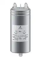
Illustrative purposes only

B32362A2157J050
General Purpose Film Capacitor, Metallized PP, Can, 150 µF, ± 5%, 250 V
⚠️ Reference pricing provided. In case of supply shortages, we will connect you with our trusted procurement partners to ensure your project's continuity.
- Manufacturer: EPCOS
- Product type: General Purpose Film Capacitors
- Capacitance:150µF; Voltage Rating:250VAC; Capacitor Dielectric Type:PP (Polypropylene); Capacitance Tolerance:± 5%; Product Range:B32362 Series; Capacitor Case Style:Can; Capacitor Termin
- Capacitance: 150µF
- Voltage(AC): 250V
- Voltage(DC): -
- Lead Spacing: -
- Product Range: B32362 Series
- Product Width: -
- Qualification: -
- Product Height: 117mm
- Product Length: -
- Dielectric Type: Metallized PP
- Humidity Rating: -
- Capacitor Mounting: Stud Mount - M12
- Capacitor Terminals: Screw
- Capacitance Tolerance: 5%
- Capacitor Case / Package: Can
- Operating Temperature Max: 85°C
- Operating Temperature Min: -40°C
| Delivery and price | |
|---|---|
| Units per pack | 120 |
| Price | 38.59 € |
| Current stock | 10+ |
| Lead time | 30 days |
Datasheet

## **Film Capacitors - Power Electronic Capacitors** ## General purpose applications |**Series/Type:**|**FilterCap MKP AC – Single phase**| |---|---| |**Ordering code:**|**B3236X Series**| |Date:|2022-05-03| |Version:|08| > TDK Electronics AG 2022. Reproduction, publication and dissemination of this publication, enclosures hereto and the information contained therein without TDK Electronics' prior express consent is prohibited. **Film Capacitors - Power Electronic Capacitors General purpose applications** **B3236X Series FilterCap MKP AC – Single phase** ## **Construction and general data** |Dielectric|Metallized polypropylene film| |---|---| |Resin filling|Non PCB, soft polyurethane| |Safety device|Overpressure disconnector, self-healing technology| |Mounting and grounding|Stud on bottom of aluminum can| |Cooling|Naturally air-cooled (or forced air cooling)| |Degree ofprotection|IP00| |Discharge resistor|Upon request| |Reference standards|IEC 61071, UL 810, GB/T 17702, RoHS compliance, CE<br>Optional IEC 60831| |Safety approvals|UL 810 approval file: E106388| |Terminals|B32361 (M6) and B32362 (M10) series: Screw terminals| **==> picture [171 x 9] intentionally omitted <==** **----- Start of picture text -----**<br> B32361 B32362<br>**----- End of picture text -----**<br> ## **Figure 1:** Capacitor MKP-AC series B32361* and B32362* CAP PW PD 2022-05-03 Please read _Cautions and warnings_ and _Important notes_ at the end of this document. Page 2 of 24 ~~LT~~ **Film Capacitors - Power Electronic Capacitors B3236X Series General purpose applications FilterCap MKP AC – Single phase** ## **Specifications and characteristics** Rated capacitance CR: 10 … 600 μF, Tolerance: ±5% |**Voltage VRMS(line to line)**|**Rated AC voltage VR (line to line)**|**Rated AC voltage VR (line to line)**|**DC voltage VRDC**|**DC voltage VRDC**| |---|---|---|---|---| |250|350<br>~~a~~||675|675| |330|460<br>~~ee~~||900|900| |480|680<br>~~ee~~||1200|| |**Test data**||||| |Voltage between terminals VTT||2.15•VRMS, 2 s||| |Voltage between terminals and Case VTC||4000 V AC,10 s||| |Dissipation factor tan δ at 100Hz|Dissipation factor tan δ at 100Hz|≤1.0•10-3||| |Life test||According to IEC 61071|According to IEC 61071|| |Life expectancy*||100 000 hours for VRMS,|∣ΔC/C∣≤3%|| |**Climatic category 40/70/21**||||| |Tstg**||−40 ...+85 °C||| |Tmin||−40 °C||| |Tmax***||+70 °C||| |Ths****||+85 °C||| |Max. permissible humidity||95% (test = 21 days)||| |Max. permissible altitude||2000 m above sea level|2000 m above sea level|| |**Mechanical characteristics**||||| |Terminal cross section||Screw terminals - B32361 (M6): 25 mm||Screw terminals - B32361 (M6): 25 mm2| |||Screw terminals-B32362 (M10) series: 78 mm||B32362 (M10) series: 78 mm2| |Max. torque (case)||M12: 12 Nm||| |Max. torque (for screw terminal)||M6: 4 Nm (B32361 series)||M6: 4 Nm (B32361 series)| |||M10: 10 Nm (B32362 series)||| * Note that this life expectancy occurs for the worst case with a maximum temperature hot-spot of +85° Celsius degree. For other operation temperatures please check the life time curve for further details. **:Tstg – Storage temperature. ***:Tmax– Maximum operation ambient temperature. ****:Ths– Maximum temperature allowed at the capacitors hot spot. Considering mounting position with terminals to the top. For other mounting positions, please request evaluation. ## **Considering mounting position with terminals to the top. For other mounting positions, please request evaluation.** CAP PW PD 2022-05-03 Please read _Cautions and warnings_ and _Important notes_ at the end of this document. Page 3 of 24 **Film Capacitors - Power Electronic Capacitors B3236X Series General purpose applications FilterCap MKP AC – Single phase** |**Design data**|| |---|---| |Dimensions (D x H)|According to specification table| |Weight approx.|According to specification table| |Max. terminal current|M6: 25 A (B32361)| ||M10: 50 A (B32362)| ## **Electrical characteristics: Clearance and creepage distances** |**Diameter**<br>**mm**|**Terminal to terminal**|**Terminal to terminal**|**Terminal to terminal**| |---|---|---|---| ||**Min.**<br>**clearance**<br>**Mm**|**Min.**<br>**creepage**<br>**mm**|**Min.**<br>**clearance**<br>**mm**| |63.5|23|34|13| |75|25|55|14| |85|25|63|17| CAP PW PD 2022-05-03 Please read _Cautions and warnings_ and _Important notes_ at the end of this document. Page 4 of 24 **Film Capacitors - Power Electronic Capacitors General purpose applications** **B3236X Series FilterCap MKP AC – Single phase** ## **Capacitor catalog number (type or series designation)** |**FilterCap MKP AC series**|**FilterCap MKP AC series**|**FilterCap MKP AC series**|**FilterCap MKP AC series**|**FilterCap MKP AC series**|**A**|**B**|**C**|**D**|**D**|**E**|**F**|**G**|**H**|**I**| |---|---|---|---|---|---|---|---|---|---|---|---|---|---|---| |1|2|3|4|5|6|7|8|9|10|11|12|13|14|15| |B|3|2|3|6|1|A|3|1|0|7|J|0|3|0| ## **A. Indicates termination type** 1 = M6 (2 x) screw terminals 2= M10 (2 x) screw terminals ## **B. Indicates revision status (any letter), in case of S letter it means customized design** ## **C. Indicates first number of voltage VRMS value (any digit)** ## **D. Indicates first and second figure of capacitance value (any two digits)** ## **E. Indicates exponent used as multiplier (any digit)** ## **F. Indicates capacitor tolerance for PEC AC capacitor** J = ±5%; K = ± 10%; ## **G. Indicates coded capacitance value** ## **H. Indicates second number of voltage VRMS value (any digit)** ## **I. Indicates Accessories (any digit)** ## **Label information Date code explanation** ## **WW Z YYYY** **WW** Z YYYY: production weeks (e.g.: 45) WW **Z** YYYY: produced in Zhuhai (China) WW Z **YYYY** : production year (e.g.: 2022) ## **Bar code explanation** Bar code consists of batch number and serial number. Batch number: 9 digits (e.g.: 123456789) Serial number: 2 or 3 digits (e.g.: 01 or 001) **Note:** the voltage values in the label have to be understood as for URAC/URMS the value shows is the URMS (VRMS) voltage and in URDC/UN the value shows is the URDC (VRDC) voltage. CAP PW PD 2022-05-03 Please read _Cautions and warnings_ and _Important notes_ at the end of this document. Page 5 of 24 ~~SS~~ **Film Capacitors - Power Electronic Capacitors B3236X Series General purpose applications FilterCap MKP AC – Single phase** ## **Dimensional drawings** **==> picture [172 x 29] intentionally omitted <==** **----- Start of picture text -----**<br> After Safety<br>Before Safety Device operation<br>Device operation<br>**----- End of picture text -----**<br> **==> picture [477 x 564] intentionally omitted <==** **----- Start of picture text -----**<br> After Safety<br>Before Safety<br>Device operation<br>Device operation<br>abel<br>|<br>“<br>—<br>=<br>® | @) (©<br>Figure 2: Series B32361 Figure 3: Series B32362 (D = 75 mm)<br>**----- End of picture text -----**<br> CAP PW PD 2022-05-03 Please read _Cautions and warnings_ and _Important notes_ at the end of this document. Page 6 of 24 **Film Capacitors - Power Electronic Capacitors General purpose applications** **B3236X Series FilterCap MKP AC – Single phase** **==> picture [170 x 24] intentionally omitted <==** **----- Start of picture text -----**<br> After Safety<br>Before Safety Device operation<br>Device operation<br>**----- End of picture text -----**<br> **Figure 4:** Series B32362 (D = 85 mm) CAP PW PD 2022-05-03 Please read _Cautions and warnings_ and _Important notes_ at the end of this document. Page 7 of 24 **Film Capacitors - Power Electronic Capacitors General purpose applications** **B3236X Series FilterCap MKP AC – Single phase** ## **Installation space requirements** 1) A minimum distance of 20 mm between the capacitors is necessary to maintain sufficient cooling. 2) Keep at least 20 mm space above the capacitor and do not attach any mounting components at the crimp or on top. This gap will allow a longitudinal extension of the can in order to ensure that the overpressure disconnector can fully extend. **Figure 5:** Installation space requirements **Note:** For further details, please check installation manual for AC filtering capacitors. CAP PW PD 2022-05-03 Please read _Cautions and warnings_ and _Important notes_ at the end of this document. Page 8 of 24 **Film Capacitors - Power Electronic Capacitors General purpose applications** **B3236X Series FilterCap MKP AC – Single phase** ## **Technical data of standard products** ## **B32361 series – M6 screw terminals** |**VR /VRMS**<br>**V**|**CR**<br>**μF **|**Ordering code**|**Imax**<br>**A**|**Î**<br>**A**|**Is**<br>kA|**Rs**<br>mΩ|**Lself**<br>nH|**D**<br>**mm**|**H**<br>**mm**|**Weight**<br>**kg**|**Packing**<br>**unit**| |---|---|---|---|---|---|---|---|---|---|---|---| |350 /<br>250|50<br>60<br>70<br>80<br>100<br>150<br>200|B32361A2506J050|25<br>25<br>25<br>25<br>25<br>25<br>25|1250 3.8<br>1500 4.5<br>1300 3.8<br>1500 4.4<br>1200 3.6<br>1300 4.0<br>1600 4.8|1250 3.8<br>1500 4.5<br>1300 3.8<br>1500 4.4<br>1200 3.6<br>1300 4.0<br>1600 4.8|3.7<br>3.6<br>4.2<br>4.1<br>5.5<br>6.3<br>6.3|195 63.5 70<br>195 63.5 70<br>220 63.5 82<br>220 63.5 82<br>225 63.5 107<br>265 63.5 132<br>275 63.5 142|195 63.5 70<br>195 63.5 70<br>220 63.5 82<br>220 63.5 82<br>225 63.5 107<br>265 63.5 132<br>275 63.5 142|195 63.5 70<br>195 63.5 70<br>220 63.5 82<br>220 63.5 82<br>225 63.5 107<br>265 63.5 132<br>275 63.5 142|0.3<br>0.3<br>0.3<br>0.3<br>0.4<br>0.5<br>0.6|12<br>12<br>12<br>12<br>12<br>12<br>12| |||B32361A2606J050|||||||||| |||B32361A2706J050|||||||||| |||B32361A2806J050|||||||||| |||B32361A2107J050|||||||||| |||B32361A2157J050|||||||||| |||B32361B2207J050|||||||||| |460 /<br>330|50<br>60<br>70<br>80<br>100|B32361B3506J030|18<br>18<br>20<br>25<br>25|920<br>720<br>840<br>960<br>880|2.7<br>2.1<br>2.5<br>2.8<br>2.6|4.4<br>6.2<br>5.8<br>5.5<br>6.9|220 63.5 82<br>225 63.5 107<br>225 63.5 107<br>225 63.5 107<br>265 63.5 132|220 63.5 82<br>225 63.5 107<br>225 63.5 107<br>225 63.5 107<br>265 63.5 132|220 63.5 82<br>225 63.5 107<br>225 63.5 107<br>225 63.5 107<br>265 63.5 132|0.3<br>0.4<br>0.4<br>0.4<br>0.5|12<br>12<br>12<br>12<br>12| |||B32361A3606J030|||||||||| |||B32361A3706J030|||||||||| |||B32361A3806J030|||||||||| |||B32361B3107J030|||||||||| |680 /<br>480|10<br>15<br>20<br>25<br>30<br>40<br>50<br>60<br>70|B32361A4106J080|10<br>15<br>20<br>25<br>25<br>20<br>25<br>25<br>25|400<br>600<br>800<br>750<br>800<br>750<br>950<br>850<br>900|1.2<br>1.8<br>2.4<br>2.2<br>2.6<br>2.3<br>2.9<br>2.6<br>2.7|4.8<br>4.1<br>4.3<br>5.2<br>4.8<br>6.6<br>6.0<br>7.7<br>8.0|195 63.5 70<br>195 63.5 70<br>195 63.5 70<br>220 63.5 82<br>220 63.5 82<br>225 63.5 107<br>225 63.5 107<br>265 63.5 132<br>275 63.5 142|195 63.5 70<br>195 63.5 70<br>195 63.5 70<br>220 63.5 82<br>220 63.5 82<br>225 63.5 107<br>225 63.5 107<br>265 63.5 132<br>275 63.5 142|195 63.5 70<br>195 63.5 70<br>195 63.5 70<br>220 63.5 82<br>220 63.5 82<br>225 63.5 107<br>225 63.5 107<br>265 63.5 132<br>275 63.5 142|0.3<br>0.3<br>0.3<br>0.3<br>0.3<br>0.4<br>0.4<br>0.5<br>0.6|12<br>12<br>12<br>12<br>12<br>12<br>12<br>12<br>12| |||B32361A4156J080|||||||||| |||B32361A4206J080|||||||||| |||B32361A4256J080|||||||||| |||B32361A4306J080|||||||||| |||B32361A4406J080|||||||||| |||B32361A4506J080|||||||||| |||B32361A4606J080|||||||||| |||B32361A4706J080|||||||||| CAP PW PD 2022-05-03 Please read _Cautions and warnings_ and _Important notes_ at the end of this document. Page 9 of 24 **Film Capacitors - Power Electronic Capacitors General purpose applications** **B3236X Series FilterCap MKP AC – Single phase** ## **B32362 series – M10 screw terminals** |**VR /VRMS**<br>**V**|**CR**<br>**μF **|**Ordering code**<br>|**Imax**<br>**A**|**Î**<br>**A**|**Is**<br>kA|**Rs**<br>mΩ|**Lself**<br>nH|**D**<br>**mm**|**H**<br>**mm**|**Weight**<br>**kg**|**Packing**<br>**unit**| |---|---|---|---|---|---|---|---|---|---|---|---| |350 /<br>250|150<br>200<br>250<br>300<br>400<br>500<br>600|B32362A2157J050|35<br>50<br>40<br>50<br>50<br>50<br>50|1800 5.4<br>2400 7.2<br>2000 6.0<br>3600 10.8<br>4800 14.4<br>4400 13.3<br>5300 16.0|1800 5.4<br>2400 7.2<br>2000 6.0<br>3600 10.8<br>4800 14.4<br>4400 13.3<br>5300 16.0|2.5<br>2.1<br>3.0<br>1.7<br>1.5<br>1.9<br>1.8|185 75<br>185 85<br>210 75<br>200 75<br>200 85<br>230 85<br>230 85|185 75<br>185 85<br>210 75<br>200 75<br>200 85<br>230 85<br>230 85|117<br>117<br>152<br>197<br>197<br>247<br>247|0.7<br>0.8<br>0.9<br>1.1<br>1.3<br>1.7<br>1.7|12<br>12<br>12<br>12<br>12<br>12<br>12| |||B32362B2207J050|||||||||| |||B32362A2257J050|||||||||| |||B32362A2307J050|||||||||| |||B32362A2407J050|||||||||| |||B32362B2507J050|||||||||| |||B32362B2607J050|||||||||| |460 /<br>330|100<br>150<br>200<br>250<br>300<br>400|B32362A3107J030|30<br>30<br>40<br>50<br>50<br>50|1450 4.3<br>1450 4.3<br>1900 5.8<br>3600 10.8<br>4300 12.9<br>3850 11.6|1450 4.3<br>1450 4.3<br>1900 5.8<br>3600 10.8<br>4300 12.9<br>3850 11.6|2.8<br>3.7<br>3.1<br>1.7<br>1.6<br>2.1|185 75<br>210 75<br>210 85<br>200 85<br>200 85<br>240 85|185 75<br>210 75<br>210 85<br>200 85<br>200 85<br>240 85|117<br>152<br>152<br>197<br>197<br>267|0.7<br>0.9<br>1.0<br>1.3<br>1.3<br>1.8|12<br>12<br>12<br>12<br>12<br>12| |||B32362A3157J030|||||||||| |||B32362B3207J030|||||||||| |||B32362A3257J030|||||||||| |||B32362A3307J030|||||||||| |||B32362A3407J030|||||||||| |680 /<br>480|60<br>70<br>80<br>100<br>150<br>200<br>250|B32362A4606J080|30<br>50<br>50<br>50<br>50<br>50<br>50|1150 3.4<br>2050 6.2<br>1350 7.1<br>1900 5.7<br>2850 8.6<br>2850 8.5<br>3200 9.6|1150 3.4<br>2050 6.2<br>1350 7.1<br>1900 5.7<br>2850 8.6<br>2850 8.5<br>3200 9.6|3.2<br>1.7<br>1.6<br>2.3<br>1.9<br>2.3<br>2.3|185 75<br>180 75<br>180 75<br>200 75<br>200 85<br>230 85<br>240 85|185 75<br>180 75<br>180 75<br>200 75<br>200 85<br>230 85<br>240 85|117<br>147<br>147<br>197<br>197<br>247<br>267|0.7<br>0.9<br>0.9<br>1.1<br>1.3<br>1.7<br>1.8|12<br>12<br>12<br>12<br>12<br>12<br>12| |||B32362A4706J080|||||||||| |||B32362A4806J080|||||||||| |||B32362A4107J080|||||||||| |||B32362A4157J080|||||||||| |||B32362A4207J080|||||||||| |||B32362A4257J080|||||||||| ## **Display of ordering codes for TDK Electronics products** The ordering code for one and the same product can be represented differently in data sheets. data books. other publications. on the company website. or in order-related documents such as shipping notes. order confirmations and product labels. **The varying representations of the ordering codes are due to different processes employed and do not affect the specifications of the respective products** . Detailed information can be found on the Internet under www.tdkelectronics.tdk.com/orderingcodes. CAP PW PD 2022-05-03 Please read _Cautions and warnings_ and _Important notes_ at the end of this document. Page 10 of 24 ~~Lo~~ **Film Capacitors - Power Electronic Capacitors B3236X Series General purpose applications FilterCap MKP AC – Single phase** ## **Terms** ## **Design** The winding element of the MKP capacitor consists of metallized polypropylene film. This winding construction achieves low losses and a high pulse-current withstand capability. Soft PU resin is used for impregnation of the capacitor. ## **Contacting** The end faces of the windings are contacted by metal spraying to ensure a reliable and low-inductance connection between the leads and layers. The leads are welded or soldered to these end faces. brought out through insulating elements (plastic) and soldered to the terminals. ## **Impregnation** All hollows between the windings and between the windings and the case are filled with an impregnating agent. Besides increasing dielectric strength. this improves heat dissipation from inside a capacitor. The impregnating agents that we use are free of PCB and halogens. ## **Self-healing** All MKP capacitors are self-healing. i.e. voltage breakdowns heal in a matter of microseconds and hence do not produce a short circuit. Breakdowns can occur under heavy electrical load as a result of weaknesses or pores in the dielectric. The integrity of self-healing capacitors is not affected by such breakdowns. 1. Dielectric (Polypropylene) 2. Metallization 3. Material-displacing shock wave 4. Air gap with metal vapor - 5.6. Plasma zone 7. Boundary layer between gas-phase dielectric and plasma zones 8. Puncture channel 9. Gas-phase dielectric 10. Zone of displaced metallization and dielectric **Figure 6:** Description of Self-healing technology CAP PW PD 2022-05-03 Please read _Cautions and warnings_ and _Important notes_ at the end of this document. Page 11 of 24 **Film Capacitors - Power Electronic Capacitors General purpose applications** **B3236X Series FilterCap MKP AC – Single phase** When a breakdown occurs. the dielectric in a breakdown channel is broken down into its atomic components by the electric arc that forms between the electrodes. At the high temperatures of as much as 6000 K. a plasma is created that explodes out of the channel region and pushes the dielectric layers apart. The actual self-healing process starts with the continuation of the electric arc in the propagating plasma. Here the metal layers are removed from the metal edges by evaporation. Insulation areas are formed. The rapid expansion of the plasma beyond the areas of insulation and its cooling in the areas of less field strength allow the discharge to extinguish after a few microseconds. The area of insulation that is created is highly resistive and voltage-proof for all operating requirements of the capacitor. The self-healing breakdown is limited in current and so it does not represent a short circuit. The self-healing process is so brief and low in energy that the capacitor also remains fully functional during the breakdown. ## **Characteristics** ## **Equivalent circuit diagram** Any real capacitor can be modelled by the following schematic: **Figure 7:** Equivalent circuit diagram |**Symbol**|**Description**|**Unit**| |---|---|---| |_Ls_|series inductance|H| |_Rs_|series resistance. due to contacts(leads. sprayed metal and film metallization|Ω| |_Rp_|parallel resistance. due to insulation resistance|Ω| |_C_|capacitance|F| C. RS and LS are magnitudes that vary in the frequency domain (AC). RP is a magnitude defined in DC (insulation resistance). ## **Rated capacitance CR** It is referred to a test temperature of +20 °C and a measuring frequency range of 50 Hz to 1 kHz. ## **Capacitance tolerance range** It is the range within which the actual capacitance may differ from rated capacitance. The actual capacitance is to be measured at a temperature of +20 ° C. This range results from variances in materials and manufacturing processes. The standard manufacturing tolerance for PP film capacitors is ±10% or ‘K’ tolerance or ±5%. ‘J’ tolerance. CAP PW PD 2022-05-03 Please read _Cautions and warnings_ and _Important notes_ at the end of this document. Page 12 of 24 **Film Capacitors - Power Electronic Capacitors General purpose applications** **B3236X Series FilterCap MKP AC – Single phase** ## **Temperature dependence of capacitance** The capacitance variation in the permissible temperature range is not linear. but it is reversible. the characteristic change in capacitance ΔC/C as a function of test temperature is shown as follows: **==> picture [232 x 150] intentionally omitted <==** **----- Start of picture text -----**<br> Relative Capacitance Change<br>ΔC/C versus Temperature T<br>2%<br>0%<br>-2%<br>-4%<br>-6%<br>-8%<br>-60 -40 -20 0 20 40 60 80 100<br>T(℃)<br>ΔC/C<br>**----- End of picture text -----**<br> **Figure 8:** Temperature dependence of capacitance ## **Capacitance drift** Capacitance is subject to irreversible in addition to reversible changes. i.e. capacitance drift. the sum of all time-dependent irreversible changes of capacitance during operating life. This variation is stated in percent of the value at delivery. The typical figure is +1/−3%. ## **Rated AC voltage VR** The maximum operating peak recurrent voltage of either polarity of a reversing type waveform for which the capacitor has been designed. Unlike what is common in other standard (e.g. B32304* 3–phase capacitor series for PFC application) therefore. the rated voltage **VR is not the RMS** value. but the maximum or peak value of the capacitor voltage. The voltage at which the capacitor may be operated is dependent on other factors (especially current and frequency) besides rated voltage. ## **Voltage VRMS** It is the Root Mean Square (RMS) voltage of maximum permissible value of sinusoidal AC voltage in continuous operation. **Figure 9:** Voltage VRMS CAP PW PD 2022-05-03 Please read _Cautions and warnings_ and _Important notes_ at the end of this document. Page 13 of 24 ~~|~~ **Film Capacitors - Power Electronic Capacitors B3236X Series General purpose applications FilterCap MKP AC – Single phase** ## **Rated DC voltage VRDC** It is the maximum operating peak voltage of either polarity but of non-reversing type waveform. for which the capacitor has been designed. for continuous operation. ## **Non-recurrent surge voltage VS** A peak voltage induced by a switching or any other disturbance of the system which is allowed for a limited number of times and for durations shorter than the basic period. **Figure 10:** Non-recurrent surge voltage VS Maximum duration: 50 ms/pulse Maximum number of occurrences: 1000 (during load) ## **Max. Recurrent peak voltage** û This is the permissible. max. Recurrent peak voltage that may appear for max.1% of the period. **Figure 11:** Max. Recurrent peak voltage û ## **Symmetric alternating voltage** û𝒂 The peak values of a symmetrical alternating voltage applied to the capacitor is a decisive factor for the dielectric losses. For AC capacitors: ûac = VR ## **Insulation voltage Vi** It is the rms rated value of the insulation voltage of capacitive elements and terminals to case or earth. If not specified. the rms value of the insulating voltage is equivalent to the rated voltage divided by √2 . ## **Maximum current Imax** It is the maximum rms current for continuous operation which could not be higher than maximum terminal current. Note that rms current with different harmonic distortions could generate different self-heating CAP PW PD 2022-05-03 Please read _Cautions and warnings_ and _Important notes_ at the end of this document. Page 14 of 24 **Film Capacitors - Power Electronic Capacitors General purpose applications** **B3236X Series FilterCap MKP AC – Single phase** temperatures. A higher current than Imax value could be possible if the hot-spot temperature (Ths) is lower than 85 ℃ and self-heating temperature is lower 25 °C (avoiding local over heating). On the contrary. same rms current with more harmonic distortions at higher frequency could have higher selfheating temperature that makes Ths higher than 85 °C (dangerous for capacitor). For that reason. **we strongly suggest end customers to qualify capacitor using samples with thermal couples temperature sensor (upon request) in order to verify the real operating temperature inside of capacitor under real application or to check with TDK company for detail discussions.** ## **Maximum peak current** I[̂] It is the maximum current amplitude which occurs instantaneously during continuous operation. The maximum peak current and the maximum rate of voltage rise (dV/dt)max on a capacitor are related as follows: **==> picture [99 x 34] intentionally omitted <==** ## **Maximum surge current** Is It is the peak non-repetitive current induced by switching or any other disturbance of the system permitted for a limited number of times. at durations shorter than the basic period. **==> picture [89 x 34] intentionally omitted <==** Maximum duration: 50 ms/pulse Maximum number of occurrences: 1000 (during load) ## **Fault current (AFC)** It is a failure mode in which capacitor is intentionally internally faulted to represent dielectric breakdown that would occur within the capacitor over time. The fault current test is intended to address protection of the capacitor from available fault currents over the life of the capacitor. The maximum fault current test levels represent a complete internal dielectric breakdown in the capacitor with the maximum fault current available. The lower fault current test levels represent the various stages of internal dielectric breakdown during the life of the capacitor where the available fault current will be less. ## **Self-inductance** Lself The self-inductance is produced by the inductance of the terminals and the windings. Because of the special kind of contacting in self-healing capacitors (large area metal spraying covering all windings). the self-inductance is particularly low. It allows the resonance frequency to be determined: **==> picture [100 x 38] intentionally omitted <==** The resonance frequency is high for all capacitors accordingly. CAP PW PD 2022-05-03 Please read _Cautions and warnings_ and _Important notes_ at the end of this document. Page 15 of 24 ~~OO~~ **Film Capacitors - Power Electronic Capacitors B3236X Series General purpose applications FilterCap MKP AC – Single phase** ## **Insulation Resistance (Rins)** The dielectric of a capacitor has a large area and a short length. Even if the material is a good isolator there always flows a certain current between the charged electrodes (the current increases exponentially with the temperature). This leakage can be described as a parallel resistance with a high value. an Insulation Resistance. > **Figure 12:** Insulation Resistance (Rins) ## **Insulation resistance and self-discharge time constant** The insulation values for the individual components according to the capacitance are stated as an insulation resistance Rins in MΩ or a self-discharge time constant _τ_ in seconds. **==> picture [75 x 13] intentionally omitted <==** ## **Series resistance RS** Resistive losses occur in the electrodes in the contacting and in the inner wiring. These are comprised in the series resistance RS of a capacitor. The series resistance RS generates the ohmic losses (I[2] ⅹRS) in a capacitor. It is largely independent of frequency. The figures stated in selection charts apply to + 20 °C capacitor temperature. ## **Dissipation factor tan δ** The equivalent circuit diagram used for the losses in a capacitor can be shown as follows: **Figure 13:** Simplified equivalent circuit diagram of a capacitor |**Symbol**|**Description**|**Unit**| |---|---|---| |C|Capacitor|F| |Lself|Self-inductance|H| |ESR|Equivalent series resistance. representing the entire active power in<br>capacitor|Ω| The self-inductance and capacitance of a capacitor produce its resonance frequency (natural frequency). ## tan δ(f) = tan δ0 + Rs ∙ω ∙C From the frequency dependence of the equivalent series resistance can be derived: CAP PW PD 2022-05-03 Please read _Cautions and warnings_ and _Important notes_ at the end of this document. Page 16 of 24 ## ~~LO~~ **Film Capacitors - Power Electronic Capacitors B3236X Series General purpose applications FilterCap MKP AC – Single phase** ## ESR =[tan δ] = Rs +[tan δ][0] ω ∙C ω ∙C |**Symbol**|**Description**|**Unit**| |---|---|---| |tan δ|Dissipation factor of capacitor|-| |tan δ0|Dissipation factor of dielectric|-| |RS|Series resistance|Ω| ## **Dielectric dissipation factor tan δ0** The dissipation factor tan δ0 of the dielectric is assumed to be constant for all capacitors in their frequency range of use. The figures stated in data sheets apply to rated operation. ## **Expected Fit rate λ** The FIT (Failure In Time) of a component is defined as the number of expected failures in 10[9] hours of operation. The FIT rate is calculated on the basis of the number of components operating in the field and the estimated hours of operation. All the reports of failures are taken into consideration for this calculation. which is updated every year. The other values in the graph are given as indication and calculated based on acceleration factors. The failure criterion is capacitance drop higher than 3%. **==> picture [96 x 15] intentionally omitted <==** **----- Start of picture text -----**<br> FIT Rate at T<br>hs<br>**----- End of picture text -----**<br> **==> picture [343 x 210] intentionally omitted <==** **----- Start of picture text -----**<br> 100<br>a et<br>10 ees<br>_— a<br>1 EE<br>a<br>ee<br>0,1<br>0,7 0,8 0,9 1 1,1 1,2<br>Voltage / VRMS<br>55 ℃ 60º C 65º C 70º C 75 ℃ 85º C<br>FIT<br>**----- End of picture text -----**<br> **Figure 14:** Expected Fit rate λ CAP PW PD 2022-05-03 Please read _Cautions and warnings_ and _Important notes_ at the end of this document. Page 17 of 24 **Film Capacitors - Power Electronic Capacitors B3236X Series General purpose applications FilterCap MKP AC – Single phase** ## **Thermal design** In order to scale a capacitor correctly for a particular application. the permissible ambient temperature has to be determined. This can be taken from the diagram “Permissible ambient temperature TA vs total power dissipation P ” after calculating the power dissipation (for further details please check individual data sheets). ## **Calculation of power dissipation P** The total power dissipation P is composed of the dielectric losses (PD) and the resistive losses (PR): Generally a secondary sinusoidal AC voltage can be used for calculating with sufficient accuracy. ## P = PD + PR PD = û2ac ∙π ∙f0 ∙C ∙tan δ0 |**Symbol**|**Description**|**Unit**| |---|---|---| |ûac|Peak value of symmetrical AC voltage applied to capacitor|V| |f0|Fundamental frequency|Hz| |C|Capacitance|F| |tan δ0|Dissipation factor of dielectric|| ## PR = I[2] ∙RS |**Symbol**|**Description**|**Unit**| |---|---|---| |I|RMS value of capacitor current|A| |RS|Series resistance at maximum hot-spot temperature|Ω| The RS figure at maximum hot-spot temperature is used to calculate the resistive losses. In selection charts and data sheets the figure is stated for 20 ℃ capacitor temperature. The conversion factor is as follows: **==> picture [115 x 13] intentionally omitted <==** ## **Thermal resistance Rth** The thermal resistance is defined as the ratio of a temperature difference and the power dissipation produced in a capacitor. The decisive factor here is ΔTcap where the temperature difference between an external reference point of the coolant (e.g. air) surrounding the capacitor and the hot spot (zone with highest temperature occurring in the component). In a steady state: **==> picture [71 x 31] intentionally omitted <==** CAP PW PD 2022-05-03 Please read _Cautions and warnings_ and _Important notes_ at the end of this document. Page 18 of 24 ## **Film Capacitors - Power Electronic Capacitors B3236X Series General purpose applications FilterCap MKP AC – Single phase** |**Symbol**|**Description**|**Unit**| |---|---|---| |Rth|Thermal resistance|K/W| |ΔTcap|Temperature difference between hot-spot and ambient|K| |P|Power dissipation|W| The temperature difference depends on a large number of different factors. The thermal resistance is a function of several parameters such as the working temperature and the power dissipation of the capacitor. After installation of the capacitor. it is necessary to verify that maximum hot-spot temperature is not exceeded at extreme service conditions. For detail calculations. please refer to single datasheet part number for further details. ## **Life expectancy tLD** The life expectancy tLD is based on the exclusive effect of Voltage and Temperature (hot-spot Ths) applied to the capacitor dielectric and electrodes (other factors are not considered in the model such as environmental or mechanical effects). Hot Spot Temperature (Ths): as the sum of ambient temperature plus the heating induced by the current (IRMS) in the dielectric which is measured inside of capacitor. Current is an indirect parameter under consideration which affects the temperature Ths. Lifetime estimation formula as follows: > [V][1] n t = t 2 1 ∙e[(T][1][−T][2][)/A] ~~(-)~~ V2 |**Symbol**|**Description**|**Unit**| |---|---|---| |t2|Estimated lifetime at temperature T2and Voltage V2|hour| |t1|Reference life expectancy (e.g. 100 000 hours for VR∣ΔC/C∣≤3%)|hour| |V2|Variable Voltage (Rated AC voltage)|VAC| |V1|Reference Voltage (Rated AC voltage)|VAC| |T1|Reference temperature (e.g. 70℃)|℃| |T2|Variable temperature|℃| |A|Acceleration factor of temperature|-| |n|Acceleration factor of voltage|-| CAP PW PD 2022-05-03 Please read _Cautions and warnings_ and _Important notes_ at the end of this document. Page 19 of 24 **Film Capacitors - Power Electronic Capacitors B3236X Series General purpose applications FilterCap MKP AC – Single phase** ## **Lifetime Expectancy Graphs** The lifetime estimations below show the standard expected lifetime of 100000 hours (at +85 °C hotspot) are only theoretical calculations based on endurance test results performed according to IEC61071 standard during operation as shown in figure 15. **Figure 15:** Expected lifetime in hours at different hotspot temperatures (Ths) and voltages VRMS. CAP PW PD 2022-05-03 Please read _Cautions and warnings_ and _Important notes_ at the end of this document. Page 20 of 24 **Film Capacitors - Power Electronic Capacitors General purpose applications** **B3236X Series FilterCap MKP AC – Single phase** ## **Cautions and warnings** - In case of dents of more than 1 mm depth or any other mechanical damage. capacitors must not be used at all. - Check tightness of the connections/terminals periodically. - The energy stored in capacitors may be lethal. To prevent any chance of shock. discharge and short-circuit the capacitor before handling. - Failure to follow cautions may result. worst case. in premature failures. bursting and fire. - Protect the capacitor properly against over current and short circuit. - TDK Electronics is not responsible for any kind of possible damages to persons or things due to improper installation and application of capacitors for power electronics. ## **Safety** - Electrical or mechanical misapplication of capacitors may be hazardous. Personal injury or property damage may result from bursting of the capacitor or from expulsion melted material due to mechanical disruption of the capacitor. - Ensure good. effective grounding for capacitor enclosures. - Observe appropriate safety precautions during operation (self-recharging phenomena and the high energy contained in capacitors). - Handle capacitors carefully. because they may still be charged even after disconnection. - The terminals of capacitors. connected bus bars and cables as well as other devices may also be energized. - Follow good engineering practice. - The maximum permissible fault current (AFC) of 10 kA in accordance with the UL 810 standard must be assured by the application. ## **Thermal load** - After installation of the capacitor. it is necessary to verify that maximum hot-spot temperature is not exceeded at extreme service conditions. ## **Mechanical protection** - The capacitor has to be installed in a way that mechanical damages and dents in the aluminum can are avoided. ## **Storage and operating conditions** - Do not use or store capacitors in corrosive atmosphere. especially where chloride gas. sulfide gas. acid. alkali. salt or the like are present. In dusty environments regular maintenance and cleaning especially of the terminals is required to avoid conductive path between phases and/or phases and ground. CAP PW PD 2022-05-03 Please read _Cautions and warnings_ and _Important notes_ at the end of this document. Page 21 of 24 **Film Capacitors - Power Electronic Capacitors B3236X Series General purpose applications FilterCap MKP AC – Single phase** - Capacitors must not be stored in high temperatures and/or high humidity for long periods. We recommend the following storage conditions. - Storage temperature -40 °C ~ +40 °C - Maximum relative humidity 80%. no dew allowed on the capacitor - Storage should not exceed 2 years (from datecode printed on the capacitor). After 1 year of storage time. capacitors must be check electrically. ## **Overpressure disconnector** - To ensure full functionality of an overpressure safety device disconnector. the following must be observed: 1. The elastic elements must not be hindered. i.e. - Connecting lines must be flexible leads (cables) - There must be sufficient space (min.20 mm) for expansion above the connections - Metal cover must not be retained by rigid parts like bus bars. 2. Stress parameters of the capacitor must be within the IEC 61071-2017 specification. NOTE 1 As the actual conditions can be significantly different in service. the behavior at the end of life may also be different. Stored energy. expected short-circuit current. duration of failure current (and so on) has to be considered in the application. Compliance with IEC61071-5.16 does not guarantee safe end of life of a capacitor. NOTE 2 Successful completion of the IEC61071-5.16 test is not sufficient to guarantee the total safe failure of the components in service. For this reason. there is a residual risk of fire and/or explosions that has to be carefully taken in consideration. ## **Service life expectancy** - Electrical components do not have an unlimited service life expectancy; this applies to self-healing capacitors. too. The maximum service life expectancy may vary depending on the application the capacitor is used in. - The lifetime only considers the effects of voltage and temperature based on the qualified results of long endurance test. Therefore. the lifetime is for reference and does not represent the actual service life of the capacitor. nor does it represent the quality assurance requirements. ## **Display of ordering codes for TDK Electronics products** The ordering code for one and the same product can be represented differently in data sheets. data books. other publications. on the company website. or in order-related documents such as shipping notes. order confirmations and product labels. **The varying representations of the ordering codes are due to different processes employed and do not affect the specifications of the respective products** . Detailed information can be found on the Internet under www.tdk-electronics.tdk.com/orderingcodes. CAP PW PD 2022-05-03 Please read _Cautions and warnings_ and _Important notes_ at the end of this document. Page 22 of 24 ## **Important notes** The following applies to all products named in this publication: 1. Some parts of this publication contain **statements about the suitability of our products for certain areas of application** . These statements are based on our knowledge of typical requirements that are often placed on our products in the areas of application concerned. We nevertheless expressly point out **that such statements cannot be regarded as binding statements about the suitability of our products for a particular customer application.** As a rule we are either unfamiliar with individual customer applications or less familiar with them than the customers themselves. For these reasons, it is always ultimately incumbent on the customer to check and decide whether a product with the properties described in the product specification is suitable for use in a particular customer application. 2. We also point out that **in individual cases, a malfunction of electronic components or failure before the end of their usual service life cannot be completely ruled out in the current state of the art, even if they are operated as specified.** In customer applications requiring a very high level of operational safety and especially in customer applications in which the malfunction or failure of an electronic component could endanger human life or health (e.g. in accident prevention or lifesaving systems), it must therefore be ensured by means of suitable design of the customer application or other action taken by the customer (e.g. installation of protective circuitry or redundancy) that no injury or damage is sustained by third parties in the event of malfunction or failure of an electronic component. 3. **The warnings, cautions and product-specific notes must be observed.** 4. In order to satisfy certain technical requirements, **some of the products described in this publication may contain substances subject to restrictions in certain jurisdictions (e.g. because they are classed as hazardous)** . Useful information on this will be found in our Material Data Sheets on the Internet (www.tdk-electronics.tdk.com/material). Should you have any more detailed questions, please contact our sales offices. 5. We constantly strive to improve our products. Consequently, **the products described in this publication may change from time to time** . The same is true of the corresponding product specifications. Please check therefore to what extent product descriptions and specifications contained in this publication are still applicable before or when you place an order. We also **reserve the right to discontinue production and delivery of products** . Consequently, we cannot guarantee that all products named in this publication will always be available. The aforementioned does not apply in the case of individual agreements deviating from the foregoing for customer-specific products. 6. Unless otherwise agreed in individual contracts, **all orders are subject to our General Terms and Conditions of Supply.** 7. **Our manufacturing sites serving the automotive business apply the IATF 16949 standard.** The IATF certifications confirm our compliance with requirements regarding the quality management system in the automotive industry. Referring to customer requirements and customer specific requirements (“CSR”) TDK always has and will continue to have the policy of respecting individual agreements. Even if IATF 16949 may appear to support the acceptance of unilateral requirements, we hereby like to emphasize that **only requirements mutually agreed upon can and will be implemented in our Quality Management System.** For clarification purposes we like to point out that obligations from IATF 16949 shall only become legally binding if individually agreed upon. Page 23 of 24 **Important notes** 8. The trade names EPCOS, CarXield, CeraCharge, CeraDiode, CeraLink, CeraPad, CeraPlas, CSMP, CTVS, DeltaCap, DigiSiMic, ExoCore, FilterCap, FormFit, LeaXield, MiniBlue, MiniCell, MKD, MKK, ModCap, MotorCap, PCC, PhaseCap, PhaseCube, PhaseMod, PhiCap, PowerHap, PQSine, PQvar, SIFERRIT, SIFI, SIKOREL, SilverCap, SIMDAD, SiMic, SIMID, SineFormer, SIOV, ThermoFuse, WindCap, XieldCap are **trademarks registered or pending** in Europe and in other countries. Further information will be found on the Internet at www.tdk-electronics.tdk.com/trademarks. ## Release 2020-06 Page 24 of 24
Updated at March 28, 2026
About Novapart
Novapart is a B2B electronic component broker specialising in stock shortages and cost reduction. We source hard-to-find parts and identify compliant alternatives across a catalogue of 410,000+ components from 500+ manufacturers.
Learn more →Stock Shortage Specialist
When a component is unavailable, discontinued or has an unacceptable lead time, we tap into our network of vetted European and Asian distributors to source what you need — without compromising on quality or traceability.
Request a quote →Compliant Alternatives
We identify pin-to-pin, electrically equivalent substitutes that meet the same certifications (RoHS, AEC-Q100, REACH) as your original specification — validated against datasheets, not just part numbers. Often at a lower cost.
BOM Analysis service →