


B25654A8137K001
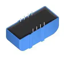
Power Film Capacitor, Film / Foil PP, 135 µF, ± 10%, DC Link, Through Hole
- Manufacturer: TDK
- Product type: Power Film Capacitors
- ESR: 780µohm
- SVHC: No SVHC (25-Jun-2025)
- Capacitance: 135µF
- Voltage(AC): -
- Voltage(DC): 850V
- Lead Spacing: 40.5mm
- Peak Current: 5.8kA
- dv/dt Rating: -
- Output (kvar): -
- Product Range: xEVCap B25654 Series
- Product Width: 49.5mm
- Qualification: AEC-Q200
- Product Height: 40.5mm
- Product Length: 109mm
- Ripple Current: -
- Dielectric Type: Film / Foil PP
- Humidity Rating: GRADE II (Test Condition A)
- Product Diameter: -
- Capacitor Mounting: Through Hole
- RMS Current (Irms): 50A
- Capacitor Terminals: PC Pin
- Typical Applications: DC Link
- Capacitance Tolerance: ± 10%
- Capacitor Case / Package: -
- Operating Temperature Max: 105°C
- Operating Temperature Min: -55°C
| Delivery and price | |
|---|---|
| Units per pack | 20 |
| Price | 27.03 € |
| Current stock | 10+ |
| Lead time | 30 days |
## **Film Capacitors**
Capacitors for DC Link xEVCap Lead Wire
**Series/Type: B25654A*001**
Date: April 2025
TDK Electronics AG 2025. Reproduction, publication and dissemination of this publication, enclosures hereto and the information contained therein without TDK Electronics’ prior express consent is prohibited.
**Capacitors for DC Link xEVCap Lead Wire**
**B25654A*001**
## **Capacitors for DC LinkApplications**
- DC-link for main traction inverters
- For parallel connection through busbars
- Passenger cars, buses, trucks, commercial vehicles, machinery tools
## **Climatic**
- Max. operating temperature 105 °C (hot spot)
- Climatic category (IEC 60068-1): 40/105/56
## **Construction**
- Dielectric: Polypropylene (MKP)
- Plastic case (UL 94 V-0)
- Epoxy resin sealing (UL 94 V-1)
## **Features**
- Scalable and modular for different power levels and densities
- WBG semiconductors compatible
- Good self-healing properties
- Overvoltage capability
- Low ESR and low ESL
- RoHS-compatible
- Reference standard: IEC TS 63337:2024
- AEC-Q200 rev E compliant
## **Terminals**
- Lead wire, lead-free tinned
## **Delivery mode**
- Bulk (untaped)
Please read _Cautions and warnings_ and _Important notes_ at the end of this document
4/25
**2**
**Capacitors for DC Link xEVCap Lead Wire**
**B25654A*001**
## **Dimensional Drawings**
(all dimensions in mm.)
|Version|Length<br>L|Width<br>W1|Width<br>W2|Height<br>H|Pitch<br>P|X|R1|R2|Weight<br>(g)|
|---|---|---|---|---|---|---|---|---|---|
|A|85|47|49.5|40.5|40.5|27|30|22|260|
|B|97.5|35.5|38|42.5|29|33.5|36|28.3|270|
|C|109|47|49.5|40.5|40.5|39|42|34|340|
Lead diameter – Ø1.2 mm, lead height - 6 mm. P - Refers to center of lead wire terminal. X - Refers to distance from outer edge of housing to center of lead. Weight tolerance ±15%
Please read _Cautions and warnings_ and _Important notes_ at the end of this document
4/25
**3**
**Capacitors for DC Link xEVCap Lead Wire**
**B25654A*001**
## **Technical data and ordering codes**
Electrical parameters are typical values, given at room temperature and relative humidity ≤65%.
|CN<br>120 Hz<br>μF|Dimensions<br>version|Ordering code|Imax1)<br>10 kHz<br>A|ESL2)<br>1 MHz<br>nH|ESR3)<br>10 kHz<br>mΩ|Î<br>kA|Is<br>kA|MOQ<br>pcs|
|---|---|---|---|---|---|---|---|---|
|VR(105 °C) = 500 V DC ; VMAX= 525 V4); Vs= 665 V|||||||||
|200|A|B25654A5207K001|40|17|1.13|2.1|6|64|
|270|C|B25654A5277K001|50|17|0.89|2.8|8|48|
|VR= 650 V DC ; VMAX= 750 V4); Vs= 900 V|||||||||
|115|B|B25654A6117K001|60|14|0.51|2|6|60|
|130|A|B25654A6137K001|42|17|0.89|1.6|5|64|
|175|C|B25654A6177K001|55|17|0.66|2.2|6.5|48|
|VR(105 °C) = 850 V DC ; VMAX= 890 V4); Vs= 1200 V|||||||||
|80|B|B25654A8806K001|56|14|0.57|1.7|5.2|60|
|100|A|B25654A8107K001|40|17|1.04|1.4|4.2|64|
|135|C|B25654A8137K001|50|17|0.78|1.9|5.8|48|
|VR(105 °C) = 920 V DC ; VMAX= 950 V4); Vs= 1250 V|||||||||
|60|B|B25654A9606K001|55|14|0.65|1.5|4.7|60|
|75|A|B25654A9756K001|35|17|1.18|1.2|3.8|64|
|110|C|B25654A9117K001|45|17|0.89|1.6|5.1|48|
MOQ = Minimum Order Quantity, consisting of 4 packing units.
## **Composition of ordering code**
K = ±10% capacitance tolerance, J = ±5% capacitance tolerance upon request 001 = Lead wire terminals
## **Characteristics curves**
Additional technical information can be found under “Design support” on www.tdk-electronics.tdk.com.
- 1) Maximum hot spot temperature inside of each of the capacitor elements shall be limited to 105 °C. This has to be ensured by the customer. The capacitor is not tested to validate the thermal interface between capacitor, power electronics and the cooling system on component or module level. Based on the boundary operating conditions of the application the sources of thermal load could be contributed by AC, DC or leakage currents in the system.
- Insulation resistance RISO given as time constant τ = CN • RIso > 10 000 s (after 1 minute), minimum as delivered values.
- 2) Typical ESL values measured with kelvin clips by impedance analyzer.
- 3) Maximum ESR is 1.5 ● ESR typical at 10 kHz.
- 4) VMAX - Maximum voltage that can be applied to the capacitors at 105 °C for 100 h.
Please read _Cautions and warnings_ and _Important notes_ at the end of this document
4/25
**4**
**Capacitors for DC Link xEVCap Lead Wire**
**B25654A*001**
## **Testing and Standards**
Type test, applied at Room Temperature otherwise is indicated.
|Test|Reference|Test condition|Performance<br>requirement|
|---|---|---|---|
|Electrical<br>characterization|IEC TS 63337:2024|• Capacitance at 120 Hz<br>• ESR at 10 kHz<br>• ESL > 1 MHz<br>• External Insulation to case, VTC, 60<br>seconds: 2830 V if VR≤ 500 V DC<br>otherwise √2 x (2 x VR+ 1 000) V DC<br>• High Voltage between terminals VTT=<br>1.5* VR, 60 seconds<br>• High Voltage between terminals and<br>case, 60 seconds<br>• RIsoat Rated voltage, 60 seconds|Within specified limits|
|High<br>Temperature<br>Exposure<br>(Storage)|AEC Q200 Rev E|• Unpowered, 1000 hours<br>• Upper temp.: 105 °C<br>• Measurement at 24±4 hours after test<br>conclusion|No visible damage<br>|ΔC/C0| ≤ 5%<br>|ΔESR/ESR0| ≤ 100%|
|Temperature<br>Cycling|AEC Q200 Rev E|• Unpowered<br>• 1000 Cycles<br>• Lower Temp of the chamber: –55 °C<br>• Upper Temp of the Chamber: +105 °C<br>• Dwell time: 30 minutes<br>• Transition Time: 1 minute maximum<br>• Measurement at least 24 hours after<br>test conclusion|No visible damage<br>|ΔC/C0| ≤ 5%<br>|ΔESR/ESR0| ≤ 200%|
|Humidity Bias|AEC Q200 Rev E|• Rated Voltage<br>• 1000 hours<br>• 40 °C/93%RH<br>• Measurement at 24±4 hours after test<br>conclusion|No visible damage<br>|ΔC/C0| ≤ 5%<br>|ΔESR/ESR0| ≤ 100%|
|High<br>Temperature<br>Operating Life|AEC Q200 Rev E|• 1000 hours<br>• Temperature of the Chamber: 105<br>°C100% of rated voltage (VR)<br>• Measurement at 24±4 hours after test<br>conclusion<br>(see footnote)|No visible damage<br>|ΔC/C0| ≤ 5%<br>|ΔESR/ESR0| ≤ 100%|
## Footnote:
Leakage current may contribute to internal hotspots above the actual temperature of the chamber. Component High temperature operating life test is carried out with gradual increase of 10°C in test temperature from 85°C to 105°C with dwell time of 24hrs.
Please read _Cautions and warnings_ and _Important notes_ at the end of this document
4/25
**5**
**Capacitors for DC Link xEVCap Lead Wire**
**B25654A*001**
|Test|Reference|Test condition|Performance<br>requirement|
|---|---|---|---|
|External Visual|AEC Q200 Rev E|• Inspect<br>component<br>construction,<br>marking and workmanship|Within specified limits|
|Physical<br>Dimensions|AEC Q200 Rev E|• Verify physical dimensions to the<br>applicable component specification|Within specified limits|
|Terminal Strength<br>for radial THT<br>components|AEC Q200 Rev E|• Test Condition A<br>20N|Within specified limits|
|Mechanical<br>Shock|AEC Q200 Rev E|• Condition C|Within specified limits|
|Vibration|AEC Q200 Rev E|• 5_g_for 20 minutes<br>• 12 cycles each of 3 orientations<br>• Tested in a full assembly with external<br>fixation to case<br>• Test from 10 Hz - 2000 Hz|No visible damage<br>Within specified limits|
|Resistance to<br>Soldering Heat|AEC Q200 Rev E|• Condition B||
|Solderability|AEC Q200 Rev E|• Method A1, Coating Durability<br>Category 2<br>• Magnification 50x||
|Flammability|AEC Q200 Rev E|• Not required: Exposed resins and<br>plastics are V-1, V-0||
Please read _Cautions and warnings_ and _Important notes_ at the end of this document
4/25
**6**
**Capacitors for DC Link xEVCap Lead Wire**
**B25654A*001**
## **Mounting guidelines**
## **Soldering**
## **Solderability of leads**
The solderability of terminal leads is tested to IEC 60068-2-20:2008, test Ta, method 1. Before a solderability test is carried out, terminals are subjected to accelerated ageing (to IEC 60068-2-2:2007, test Ba: 4 h exposure to dry heat at 155 °C). Since the ageing temperature is far higher than the upper category temperature of the capacitors, the terminal wires should be cut off from the capacitor before the ageing procedure to prevent the solderability being impaired by the products of any capacitor decomposition that might occur.
|Solder bath temperature|235 ±5 °C|
|---|---|
|Solderingtime|2.0 ±0.5 s|
|Immersion depth|2.0 +0/–0.5 mm from capacitor bodyor seating plane|
|Evaluation criteria:<br>Visual inspection|Wetting of wire surface by new solder90%,<br>free-flowing solder|
## **Resistance to soldering heat**
Resistance to soldering heat is tested to IEC 60068-2-20:2008, test Tb, method 1. Conditions:
|Conditions:||
|---|---|
|Solder bath temperature|260 ±5 °C|
|Solderingtime|10 ±1 s|
|Immersion depth|2.0 +0/–0.5 mm from capacitor bodyor seating plane|
|Shield|Heat-absorbing board, (1.5 ±0.5) mm thick, between<br>capacitor bodyand liquid solder|
|Evaluation criteria:<br>Visual inspection<br>ΔC/C0<br>tan ∂|No visible damage<br>±5%<br>As specified in sectional specification|
## **General notes on soldering**
Permissible heat exposure loads on film capacitors are primarily characterized by the upper category temperature Tmax. Long exposure to temperatures above this type-related temperature limit can lead to changes in the plastic dielectric and thus change irreversibly a capacitor's electrical characteristics. For short exposures (as in practical soldering processes) the heat load (and thus the possible effects on a capacitor) will also depend on other factors like:
- Pre-heating temperature and time
- Forced cooling immediately after soldering
- Terminal characteristics: diameter, length, thermal resistance, special configurations (e.g. crimping)
- Height of capacitor above solder bath
- Shadowing by neighboring components
- Additional heating due to heat dissipation by neighboring components
- Use of solder-resist coatings
Please read _Cautions and warnings_ and _Important notes_ at the end of this document
4/25
**7**
**Capacitors for DC Link xEVCap Lead Wire**
**B25654A*001**
The overheating associated with some of these factors can usually be reduced by suitable countermeasures. For example, if a pre-heating step cannot be avoided, an additional or reinforced cooling process may possibly have to be included.
## **Recommendations**
As a reference, the recommended wave soldering profile for film capacitors for PCB mounting in a wave soldering process is as follows:
Body temperature should follow the description below:
- During pre-heating: Tp ≤110 °C
- During soldering: Ts ≤120 °C, ts ≤45 s
Please read _Cautions and warnings_ and _Important notes_ at the end of this document
4/25
**8**
**Capacitors for DC Link xEVCap Lead Wire**
**B25654A*001**
When SMD components are used together with leaded ones, the film capacitors should not pass into the SMD adhesive curing oven. The leaded components should be assembled after the SMD curing step. Leaded film capacitors are not suitable for reflow soldering. In order to ensure proper conditions for manual or selective soldering, the body temperature of the capacitor (Ts) must be ≤120 °C.
One recommended condition for manual soldering is that the tip of the soldering iron should be <360 °C and the soldering contact time should be no longer than 3 seconds.
## **Cleaning**
To determine whether the following solvents, often used to remove flux residues and other substances, are suitable for the capacitors described, refer to the table below:
|Type|Ethanol, isopropanol, n-propanol|n-propanol-water mixtures, water<br>with surface tension-reducing<br>tensides(neutral)|
|---|---|---|
|xEVCap|Suitable|Unsuitable|
Even when suitable solvents are used, a reversible change of the electrical characteristics may occur in uncoated capacitors immediately after they are washed. Thus, it is always recommended to dry the components (e.g. 4 h at 70 °C) before they are subjected to subsequent electrical testing.
## **Caution:**
Consult us first if you wish to embed uncoated types!
## **Embedding of capacitors in finished assemblies**
In many applications, finished circuit assemblies are embedded in plastic resins. In this case, both chemical and thermal influences of the embedding ("potting") and curing processes must be taken into account. Our experience has shown that the following potting materials can be recommended: non-flexible epoxy resins with acid-anhydride hardeners; chemically inert, non-conducting fillers; maximum curing temperature of 100 °C.
## **Caution:**
Consult us first if you wish to embed uncoated types!
Please read _Cautions and warnings_ and _Important notes_ at the end of this document
4/25
**9**
~~ee~~ **Capacitors for DC Link B25654A*001 xEVCap Lead Wire**
## **Product Marking Specification**
## **Ordering code example**
|B|25654|A|5|107|K|
|---|---|---|---|---|---|
|Components class|Series|xEVCAP type|Rated voltage|Rated capacitance|Capacitance tolerance|
|Passive||Version|5 = 500Vdc|107pF =100 μF|K =±10%|
|components|||6 = 650Vdc|||
||||8 = 850Vdc|||
||||9 = 920Vdc|||
## **Example for label (label or laser print on housing)**
## **Explanation of label text**
|B25654A8137K001<br>xEVCAP<br>130μF 850V<br>XXXXXXXXX<br>Date: MM. YY|TDK part no.<br>Product type<br>Rated capacitance and nominal voltage<br>Lot number / part Identifier<br>Manufacturing month and year|
|---|---|
## **Content of DMC code:**
Same as the label text
Please read _Cautions and warnings_ and _Important notes_ at the end of this document
4/25
**10**
**Capacitors for DC Link xEVCap Lead Wire**
**B25654A*001**
## **Cautions and warnings**
- The maximum hot spot temperature inside the capacitor elements may not exceed 105°C. This has to be ensured by the customer.
- Any exceedance of the maximum temperature of 105 °C inside each of the capacitor elements will significantly reduce its lifetime.
- In case of mechanical damage, capacitors must not be used at all.
- The energy stored in capacitors may be lethal. To prevent any chance of shock, discharge and shortcircuit the capacitor before handling.
- Failure to follow cautions may result, worst case, in premature failures, bursting and fire.
- Tinned Cu terminals of the capacitor may lead to the occurrence of whisker during capacitor supply, storage and/or during application of the capacitor. Factors for the occurrence of whisker are not determinable and outside TDK's responsibility. Therefore, customer shall be solely responsible for the risk analysis and necessary safety measures related to the occurrence of whisker.
## **Safety**
- Electrical or mechanical misapplication of capacitors may be hazardous. Personal injury or property damage may result from bursting of the capacitor or from expulsion of melted material due to mechanical disruption of the capacitor.
- Ensure good, effective grounding for capacitor enclosures.
- Observe appropriate safety precautions during operation (self recharging phenomena and the high energy stored in capacitors).
- Handle capacitors carefully, because they may still be charged even after disconnection.
- The terminals of capacitors, connected bus bars and cables as well as other devices may also be energized.
## **Thermal load**
After installation of the capacitor it is necessary to verify that maximum hot-spot temperature is not exceeded at extreme service conditions.
## **Mechanical protection**
The capacitor has to be installed in a way that mechanical damages, terminal bending and dents in the case are avoided.
## **Storage and operating conditions**
Do not use or store capacitors in corrosive atmosphere, especially where chloride gas, sulfide gas, acid, alkali, salt or the like are present. In dusty environments regular maintenance and cleaning especially of the terminals is required to avoid conductive path between phases and/or phases and ground.
## **Service life expectancy and disposal**
Electrical components do not have an unlimited service life expectancy; this applies to self-healing capacitors too. The maximum service life expectancy may vary depending on the application the capacitor is used in. TDK capacitors can be disposed through the standard process in place for uncritical industrial and automotive electronics components. Considering common government regulations they do not include quantities of critical substances, that would make a special treatment necessary. In case of uncertainty for your country please consult a local waste requirements specialist.
**11** 4/25
**Capacitors for DC Link xEVCap Lead Wire**
**B25654A*001**
## **Display of ordering codes for TDK Electronics products**
The ordering code for one and the same product can be represented differently in data sheets, data books, other publications, on the company website, or in order-related documents such as shipping notes, order confirmations and product labels. The varying representations of the ordering codes are due to different processes employed and do not affect the specifications of the respective products. Detailed information can be found on the Internet under www.tdk-electronics.tdk.com/orderingcodes.
Please read _Cautions and warnings_ and _Important notes_ at the end of this document
**12**
April
**Capacitors for DC Link xEVCap Lead Wire**
**B25654A*001**
## **Symbols and terms**
|CN<br>VRor UR <br>VMAXor<br>UMAX<br>I_max<br>ESR<br>Vs<br>î<br>Is<br>VTTor<br>UTT<br>VTCor<br>UTC<br>RIso<br>Tmin<br>Tmax|Nominal capacitance<br> Rated DC-voltage of a capacitor<br>Maximum permissible voltage that can be applied to the capacitors for specified duration at the<br>specified temperature<br>Maximum RMS capacitor current for continuous operation at 10 kHz<br>Equivalent series resistance, measured at 10 kHz<br>Non-recurrent surge voltage<br>Max. current transient amplitude during continuous operation<br>Admissible peak current transient for a limited number of time<br>(typical value: 1000 times during operation time)<br>Test voltage for capacitor, applied between terminal and terminal<br>Test voltage for capacitor, applied between terminal and case<br>Insulation resistance between capacitor terminals, measured at rated voltage for 60 s<br>Lowest permitted ambient working temperature<br>Highest permitted ambient working temperature|
|---|---|
## **Note**
Symbol “U” or “V” can be used indistinctly for the physical magnitude of voltage (electric potential difference). “U” is widely used in reference IEC standards while “V” is also widely used in datasheets and specifications.
Please read _Cautions and warnings_ and _Important notes_ at the end of this document
4/25
**13**
## **Important notes**
The following applies to all products named in this publication:
- 1 Some parts of this publication contain **statements about the suitability of our products for certain areas of application** . These statements are based on our knowledge of typical requirements that are often placed on our products in the areas of application concerned. We nevertheless expressly point out **that such statements cannot be regarded as binding statements about the suitability of our products for a particular customer application** . As a rule we are either unfamiliar with individual customer applications or less familiar with them than the customers themselves. For these reasons, it is always ultimately incumbent on the customer to check and decide whether a product with the properties described in the product specification is suitable for use in a particular customer application.
- 2 We also point out that **in individual cases, a malfunction of electronic components or failure before the end of their usual service life cannot be completely ruled out in the current state of the art, even if they are operated as specified** . In customer applications requiring a very high level of operational safety and especially in customer applications in which the malfunction or failure of an electronic component could endanger human life or health (e.g. in accident prevention or life-saving systems), it must therefore be ensured by means of suitable design of the customer application or other action taken by the customer (e.g. installation of protective circuitry or redundancy) that no injury or damage is sustained by third parties in the event of malfunction or failure of an electronic component.
- 3 **The warnings, cautions and product-specific notes must be observed** .
- 4 In order to satisfy certain technical requirements, **some of the products described in this publication may contain substances subject to restrictions in certain jurisdictions (e.g. because they are classed as hazardous)** . Useful information on this will be found in our Material Data Sheets on the Internet (www.tdk-electronics.tdk.com/material). Should you have any more detailed questions, please contact our sales offices.
- 5 We constantly strive to improve our products. Consequently, **the products described in this publication may change from time to time** . The same is true of the corresponding product specifications. Please check therefore to what extent product descriptions and specifications contained in this publication are still applicable before or when you place an order.
- We also **reserve the right to discontinue production and delivery of products** . Consequently, we cannot guarantee that all products named in this publication will always be available. The aforementioned does not apply in the case of individual agreements deviating from the foregoing for customer-specific products.
- 6 Unless otherwise agreed in individual contracts, **all orders are subject to our General Terms and Conditions of Supply** .
- 7 **Our manufacturing sites serving the automotive business apply the IATF 16949 standard** . The IATF certifications confirm our compliance with requirements regarding the quality management system in the automotive industry. Referring to customer requirements and customer specific requirements (“CSR”) TDK always has and will continue to have the policy of respecting individual agreements. Even if IATF 16949 may appear to support the acceptance of unilateral requirements, we hereby like to emphasize that **only requirements mutually agreed upon can and will be implemented in our Quality Management System** . For clarification purposes we like to point out that obligations from IATF 16949 shall only become legally binding if individually agreed upon.
**14** 4/25
## **Important notes**
- 8 The trade names EPCOS, CarXield, CeraCharge, CeraDiode, CeraLink, CeraPad, CeraPlas, CSMP, CTVS, DeltaCap, DigiSiMic, FilterCap, FormFit, InsuGate, LeaXield, MediPlas, MiniBlue, MiniCell, MKD, MKK, ModCap, MotorCap, PCC, PhaseCap, PhaseCube, PhaseMod, PhiCap, PiezoBrush, PlasmaBrush, PowerHap, PQSine, PQvar, SIFERRIT, SIFI, SIKOREL, SilverCap, SIMDAD, SiMic, SIMID, SineFormer, SIOV, SurfIND, ThermoFuse, WindCap, XieldCap are **trademarks registered or pending** in Europe and in other countries. Further information will be found on the Internet at www.tdkelectronics.tdk.com/trademarks.
## Release 2024-02
4/25
**15**
Updated at April 27, 2026
TDK Corporation is a globally recognized leader in electronic components and magnetic materials. Founded in 1935 to commercialize ferrites, the Tokyo-based company has evolved into a comprehensive manufacturer of high-performance passive components, sensors, and power electronics. TDK’s advanced materials technology serves as the foundation for its extensive portfolio, driving innovation across automotive, industrial, consumer electronics, and communication technologies. Our selection of TDK components heavily features their industry-leading passive components, with a primary focus on magnetics. TDK excels in manufacturing reliable inductive solutions, offering a vast array of power inductors and RF inductors optimized for demanding power management and high-frequency applications. Furthermore, their expertise in electromagnetic compatibility is showcased through a comprehensive range of EMC and RFI suppression products. This includes common mode chokes, power line filters, and specialized shielding materials designed to ensure superior signal integrity in complex designs. Beyond inductors and filtering components, TDK provides robust circuit protection and sensing solutions essential for modern engineering. The portfolio includes precision temperature sensing and compensation NTC thermistors, alongside TVS varistors and inrush current limiting components that safeguard sensitive electronics. Complemented by fixed value inductors, supercapacitors, and charging coils, TDK's versatile product offering delivers the reliability and performance required for sophisticated circuit design.
About Novapart
Novapart is a B2B electronic component broker specialising in stock shortages and cost reduction. We source hard-to-find parts and identify compliant alternatives across a catalogue of 410,000+ components from 500+ manufacturers.
Learn more →Stock Shortage Specialist
When a component is unavailable, discontinued or has an unacceptable lead time, we tap into our network of vetted European and Asian distributors to source what you need — without compromising on quality or traceability.
Request a quote →Compliant Alternatives
We identify pin-to-pin, electrically equivalent substitutes that meet the same certifications (RoHS, AEC-Q100, REACH) as your original specification — validated against datasheets, not just part numbers. Often at a lower cost.
BOM Analysis service →