


B25648A1887K003
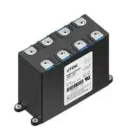
Power Film Capacitor, Bio-Based Polypropylene Film, 880 F, ± 10%, DC Link, Chassis Mount
- Manufacturer: TDK
- Product type: Power Film Capacitors
- ESR: -
- SVHC: No SVHC (25-Jun-2025)
- Capacitance: 880F
- Voltage(AC): -
- Voltage(DC): 1.6kV
- Lead Spacing: -
- Peak Current: 5kA
- dv/dt Rating: -
- Output (kvar): -
- Product Range: B25648A Series
- Product Width: 90mm
- Qualification: -
- Product Height: 170mm
- Product Length: 205mm
- Ripple Current: -
- Dielectric Type: Bio-Based Polypropylene Film
- Humidity Rating: -
- Product Diameter: -
- Capacitor Mounting: Chassis Mount
- RMS Current (Irms): 190A
- Capacitor Terminals: Screw
- Typical Applications: DC Link
- Capacitance Tolerance: ± 10%
- Capacitor Case / Package: -
- Operating Temperature Max: 75°C
- Operating Temperature Min: -40°C
| Delivery and price | |
|---|---|
| Units per pack | 6 |
| Price | 432.64 € |
| Current stock | 10+ |
| Lead time | 30 days |
## **Film Capacitors – Power Electronic Capacitors** ## PEC ModCap UHP series (high frequency) **Series/Type: ModCap UHP Ordering code: B25648A** Date: July 2025 Version: 2 TDK Electronics AG 2025. Reproduction, publication and dissemination of this publication, enclosures hereto and the information contained therein without TDK Electronics' prior express consent is prohibited. ~~hae~~ **Film Capacitors – Power Electronic Capacitors B25648A PEC ModCap UHP series (high frequency) ModCap UHP** **Rated capacitance:** 470 … 880 µF **Rated DC Voltage:** 1350… 1800 V DC ## **Construction** - Dielectric: High temperature dielectric film based on BOPP - Plastic case and cover - Dry, non PCB, resin filled - UL94 V-0 for plastic case, plastic cover and resin - Fire and smoke acc to EN 45545-2:2020: HL2-R22 and HL3-R23 for plastic case, plastic cover and resin ## **Features** - Modular design - High frequency performance, fully compatible with SiC semiconductors - High temperature operation (+105 ºC without derating) - High current density - Self-healing technology - Over-voltage capability - Very low ESL ## **Typical applications** - DC link applications with SiC power switches - DC link for renewable energy converters (solar, wind, hydrolyzer, ESS) - DC link for auxiliary drives traction applications - DC link for industrial motor drive ## **Reference Standards** - IEC 61071:2017, International Standard Capacitors for power electronics - IEC 61881-1:2010, International Standard Railway Applications-Rolling stock equipment-Capacitors for power electronics - EN 45545-2:2020, fire behaviour of materials and components ## **Terminals** - Optimized low inductance flat female terminals M6 ## **Certifications** - UL recognition planned - ISCC certification, bio circular BOPP 100%* ## **Delivery mode und packing unit** - Construction C: 4 capacitors per box *Mass-balance approach July 2025 Please read _Cautions and warnings_ and _Important notes_ at the end of this document. Page 2 of 10 **Film Capacitors – Power Electronic Capacitors PEC ModCap UHP series (high frequency)** **B25648A ModCap UHP** ## **Technical data and specifications** ## **Characteristics** |Rated capacitance CN|Up to 880 µF (see table)| |---|---| |Tolerance|K (±10%)| |Rated voltage range UN|1350 to 1800 V (see table)| |Ripple voltage Ur|Up to 282 Vpeak-peak| |(Operation bandwidth1) 2)|Up to 100 kHz| |Rated current IR(3 kHz)|(see table)| |Inductance ESL (1 MHz)2)|8 nH| |Thermal Resistance Rth3)|1.5 K/W| 1) RMS current value that corresponds to components above 100 kHz limited to 10% of total RMS. Maximum continuous losses defined for rated current at 3 kHz should not be exceeded. ESR vs frequency graph available in page 5 for losses calculation according to a specific current spectrum. For more accurate thermal calculation, please ask for FEA simulation according to your specific operation conditions. 2) Connecting all independent capacitances by external overlapped busbar as described in page 4. 3) Calculated from Tamb to THS considering natural convection and no transfer of heat through the terminals at Tamb= +75 ºC. For further information about simulation capabilities and support on specific projects, please contact CAPSimulations@tdk.com ## **Maximum ratings** Maximum permissible voltage (Umax ) UN +10% (30% of on-load daily duration) UN +15% (up to 30 min daily) UN +20% (up to 5 min daily) UN +30% (up to 1 min daily) Maximum permissible peak voltage UN +50% for 30 ms is permitted 1000 times during the lifetime of the capacitors UTC (Isolation) 4 kV UTC (Extinction) 2.5 kV (<10 pC) The average applied voltage shall not be higher than the specified voltage. It should be recognized that any significant period of operation at voltages above the rated one would reduce overall life. **Test data** Voltage test between terminals (UTT ) 1.5 UN, DC, 10 s (room temperature) ~~a~~ **Design data** Weight approx. 3.6 ± 0.1 kg Fixing 4 x Ø 6.5 mm ~~—_—~~ **Terminals** Terminations 8 x M6 x 25 x 30 mm, contact area 60 mm[2] Max. torque 6 Nm ~~ee~~ July 2025 Please read _Cautions and warnings_ and _Important notes_ at the end of this document. Page 3 of 10 **B25648A ModCap UHP** ## **Film Capacitors – Power Electronic Capacitors PEC ModCap UHP series (high frequency)** ## **Climatic category 40/75/56** |**Ө** ambmin|–40 ºC| |---|---| |**Ө** ambmax.|+75 ºC| |Storage temperature|–40 ºC ... +105 ºC| |**Ө** hotspotmax.|+105 ºC| |Humidity|RH < 93% Abs.Hum. < 25 g/m3without condensation<br>(Max. values 30 days/year)<br>RH < 45% Abs.Hum. < 18 g/m3without condensation (Mean values)| |Time test|56 days| |Maximum altitude|2000 m, higher altitude to be requested| ## **Electrical characteristics and ordering codes** |**UN**<br>**V DC**|**CR**<br>**µF**|**IN**<br>**Tamb=+75 ºC**4**)**<br>**ARMS**|**IS **<br>**kA**|**Î**<br>**kA**|**Dimensions**<br>**LxWxH**<br>**mm**|**Design / PU**|**Ordering code**| |---|---|---|---|---|---|---|---| |1350|880|205|205|5|205x90x170|C / 4pcs|B25648A1887K003| |1600|640|190|175|5|205x90x170|C / 4pcs|B25648A1647K003| |1800|470|180|150|5|205x90x170|C / 4pcs|B25648A1477K003| 4) Max. ripple current IRMS at Tamb = +75 °C at 3 kHz for a ΔTHS-Amb ≤30 °C when ESR = ESRmax, considering increase of ESR due to temperature, and not-aged capacitors. Considering natural convection (h = 12 W/m[2] K) and no transfer of heat through the terminals. For further information about simulation capabilities and support on specific projects, please contact CAPSimulations@tdk.com ## **Connection via external busbar** The ModCap is a modular solution with four independent capacitors to be connected with an external overlapped busbar. The customer busbar shall connect the terminals according to the appropriate polarity as shown in the electrical connection diagram below. ## 00:0 BU © ace Polarity A Thre July 2025 Please read _Cautions and warnings_ and _Important notes_ at the end of this document. Page 4 of 10 **Film Capacitors – Power Electronic Capacitors B25648A PEC ModCap UHP series (high frequency) ModCap UHP** ## **ESR vs frequency** ## **ESR from 1 kHz up to 150 kHz** ## **ESR from 1 kHz up to 350 kHz** July 2025 Please read _Cautions and warnings_ and _Important notes_ at the end of this document. Page 5 of 10 **Film Capacitors – Power Electronic Capacitors B25648A PEC ModCap UHP series (high frequency) ModCap UHP** ## **Life expectancy** Mean Lifetime @ UN / +105 ºC[5)] 200.000 hours[6)] @ other conditions see graph End of life criteria Capacitance drop @ 120 Hz > - 3% Increase of ESR @ 120 Hz > +50% Increase of ESR @ 1 kHz > +33% 5) Considering continuous operation at +105 ºC mean dielectric temperature. - 6) Lifetime limited to 200.000 h at +105 ºC due to aging of encapsulating materials July 2025 Please read _Cautions and warnings_ and _Important notes_ at the end of this document. Page 6 of 10 **Film Capacitors – Power Electronic Capacitors B25648A PEC ModCap UHP series (high frequency) ModCap UHP** ## **Dimensional drawings** ## Dimensions in mm July 2025 Please read _Cautions and warnings_ and _Important notes_ at the end of this document. Page 7 of 10 ~~LT~~ **Film Capacitors – Power Electronic Capacitors B25648A Cautions and Warnings ModCap UHP** ## **General safety recommendations** - When employed in power electronics applications, the capacitors run with high energy and high currents. - The energy stored in capacitors may be lethal. To prevent any risks of shocks, the capacitor should be discharged with adequate means by qualified people and short-circuited between terminals before handling. - The capacitor can contain dangerous residual charges even after long time without operation. For this reason, the electrical terminals must remain short-circuited until the capacitors are connected in the operating circuit. - TDK Electronics cannot predict all possible stresses that a power electronic capacitor can be subjected to. There is a remaining probability of power electronic capacitors showing malfunction due to excess temperature, overvoltage, wrong application, wrong installation, faulty maintenance, mechanical damage, operation at the limits of the specification or other reasons. ## **Transportation and handling** - The electrical terminals must not be used for grabbing or suspending the capacitor during transportation and handling, hold the capacitor body or fixing brackets. - Do not handle the capacitor before it is discharged. - Handle capacitors carefully, because they may still be charged even after disconnection due to faulty discharging devices. - Protect the capacitor properly against over current and short circuit. - Failure to follow cautions may result, worst case, in premature failures, bursting and fire. - Capacitor subjected to Dual Use Category 3A201. ## **Fixing** - The threaded screw 4x Ø 6.5 mm in the bottom of the capacitor must be used for fixing. ## **Storage and operating condition** - Capacitors must never be stored outside the specified temperature and humidity ranges. - Capacitors may not be stored in corrosive atmospheres, particularly not when chlorides, sulfides, acids, alkalis, salts, organic solvents, or similar substances are present. - Please read the Operating and safety instructions before use. ## **Display of ordering codes for TDK Electronics products** The ordering code for one and the same product can be represented differently in data sheets, data books, other publications, on the company website, or in order-related documents such as shipping notes, order confirmations and product labels. **The varying representations of the ordering codes are due to different processes employed and do not affect the specifications of the respective products** . Detailed information can be found on the Internet under www.tdk-electronics.tdk.com/orderingcodes. July 2025 Please read _Cautions and warnings_ and _Important notes_ at the end of this document. Page 8 of 10 ~~LT~~ **Important notes** The following applies to all products named in this publication: 1. Some parts of this publication contain **statements about the suitability of our products for certain areas of application** . These statements are based on our knowledge of typical requirements that are often placed on our products in the areas of application concerned. We nevertheless expressly point out **that such statements cannot be regarded as binding statements about the suitability of our products for a particular customer application.** As a rule we are either unfamiliar with individual customer applications or less familiar with them than the customers themselves. For these reasons, it is always ultimately incumbent on the customer to check and decide whether a product with the properties described in the product specification is suitable for use in a particular customer application. 2. We also point out that **in individual cases, a malfunction of electronic components or failure before the end of their usual service life cannot be completely ruled out in the current state of the art, even if they are operated as specified.** In customer applications requiring a very high level of operational safety and especially in customer applications in which the malfunction or failure of an electronic component could endanger human life or health (e.g. in accident prevention or lifesaving systems), it must therefore be ensured by means of suitable design of the customer application or other action taken by the customer (e.g. installation of protective circuitry or redundancy) that no injury or damage is sustained by third parties in the event of malfunction or failure of an electronic component. 3. **The warnings, cautions and product-specific notes must be observed.** 4. In order to satisfy certain technical requirements, **some of the products described in this publication may contain substances subject to restrictions in certain jurisdictions (e.g. because they are classed as hazardous)** . Useful information on this will be found in our Material Data Sheets on the Internet (www.tdk-electronics.tdk.com/material). Should you have any more detailed questions, please contact our sales offices. 5. We constantly strive to improve our products. Consequently, **the products described in this publication may change from time to time** . The same is true of the corresponding product specifications. Please check therefore to what extent product descriptions and specifications contained in this publication are still applicable before or when you place an order. We also **reserve the right to discontinue production and delivery of products** . Consequently, we cannot guarantee that all products named in this publication will always be available. The aforementioned does not apply in the case of individual agreements deviating from the foregoing for customer-specific products. 6. Unless otherwise agreed in individual contracts, **all orders are subject to our General Terms and Conditions of Supply.** 7. **Our manufacturing sites serving the automotive business apply the IATF 16949 standard.** The IATF certifications confirm our compliance with requirements regarding the quality management system in the automotive industry. Referring to customer requirements and customer specific requirements (“CSR”) TDK always has and will continue to have the policy of respecting individual agreements. Even if IATF 16949 may appear to support the acceptance of unilateral requirements, we hereby like to emphasize that **only requirements mutually agreed upon can and will be implemented in our Quality Management System.** For clarification purposes we like to point out that obligations from IATF 16949 shall only become legally binding if individually agreed upon. Page 9 of 10 ## ~~LT~~ **Important notes** 8. The trade names EPCOS, CarXield, CeraCharge, CeraDiode, CeraLink, CeraPad, CeraPlas, CSMP, CTVS, DeltaCap, DigiSiMic, FilterCap, FormFit, InsuGate, LeaXield, MediPlas, MiniBlue, MiniCell, MKD, MKK, ModCap, MotorCap, PCC, PhaseCap, PhaseCube, PhaseMod, PhiCap, PiezoBrush, PlasmaBrush, PowerHap, PQSine, PQvar, SIFERRIT, SIFI, SIKOREL, SilverCap, SIMDAD, SiMic, SIMID, SineFormer, SIOV, SurfIND, ThermoFuse, WindCap, XieldCap are **trademarks registered or pending** in Europe and in other countries. Further information will be found on the Internet at www.tdk-electronics.tdk.com/trademarks. ## Release 2024-02 Page 10 of 10
Updated at April 27, 2026
TDK Corporation is a globally recognized leader in electronic components and magnetic materials. Founded in 1935 to commercialize ferrites, the Tokyo-based company has evolved into a comprehensive manufacturer of high-performance passive components, sensors, and power electronics. TDK’s advanced materials technology serves as the foundation for its extensive portfolio, driving innovation across automotive, industrial, consumer electronics, and communication technologies. Our selection of TDK components heavily features their industry-leading passive components, with a primary focus on magnetics. TDK excels in manufacturing reliable inductive solutions, offering a vast array of power inductors and RF inductors optimized for demanding power management and high-frequency applications. Furthermore, their expertise in electromagnetic compatibility is showcased through a comprehensive range of EMC and RFI suppression products. This includes common mode chokes, power line filters, and specialized shielding materials designed to ensure superior signal integrity in complex designs. Beyond inductors and filtering components, TDK provides robust circuit protection and sensing solutions essential for modern engineering. The portfolio includes precision temperature sensing and compensation NTC thermistors, alongside TVS varistors and inrush current limiting components that safeguard sensitive electronics. Complemented by fixed value inductors, supercapacitors, and charging coils, TDK's versatile product offering delivers the reliability and performance required for sophisticated circuit design.
About Novapart
Novapart is a B2B electronic component broker specialising in stock shortages and cost reduction. We source hard-to-find parts and identify compliant alternatives across a catalogue of 410,000+ components from 500+ manufacturers.
Learn more →Stock Shortage Specialist
When a component is unavailable, discontinued or has an unacceptable lead time, we tap into our network of vetted European and Asian distributors to source what you need — without compromising on quality or traceability.
Request a quote →Compliant Alternatives
We identify pin-to-pin, electrically equivalent substitutes that meet the same certifications (RoHS, AEC-Q100, REACH) as your original specification — validated against datasheets, not just part numbers. Often at a lower cost.
BOM Analysis service →