
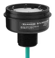


B-TL70POE-QPD.
POE BASE MODULE, TOWER LIGHT, W/CABLE
- Manufacturer: BANNER ENGINEERING
- Product type: Signal Indicator Accessories
- Accessory Type:PoE Base Module; For Use With:Banner Engineering TL70 Pro Series 70mm Tower Lights; Product Range:TL70 Pro Series 23AM1408
- SVHC: No SVHC (15-Jan-2018)
- For Use With: Banner Engineering TL70 Pro Series 70mm Tower Lights
- Product Range: TL70 Pro Series
- Accessory Type: PoE Base Module
| Delivery and price | |
|---|---|
| Units per pack | 1 |
| Price | 206.96 € |
| Current stock | 10+ |
| Lead time | 30 days |
TL70 Pro Tower Light with IO-Link

## Features

70 mm IO-Link Controlled Modular Multicolor RGB Tower Light

- Modular, IO-Link controlled LED indicator with extremely bright and uniform light

- • Illuminated segments provide easy-to-see operator guidance and indication of equipment status • IO-Link gives full access to color, flashing, and dimming settings, as well as advanced animations like run and level modes which provides dynamic response to changing machine conditions

- • Multiple audible options available • 18 V DC to 30 V DC operation • Up to six segments, or five segments plus audible, in one device • Modularity gives the user flexibility to customize tower lights as needed and change positions in the field

- • Also available preassembled for easy installation

## Models

## TL70 Pro with IO-Link Base

**==> picture [500 x 240] intentionally omitted <==**

**----- Start of picture text -----**<br>
Housing Style Control — Connection [(1)] Housing Color<br>B-TL70 P K — Q<br>Q = Integral 4-pin M12 male quick-disconnect connector Blank = Black<br>Base Module P = Pro K = IO-Link<br>QP = 150 mm (6 in) PVC-jacketed cable with a 4-pin M12 male quick-<br>disconnect connector C = Gray<br>TL70 Pro Light Segments<br>Housing Style — Color Housing Color<br>SG-TL70 P — RGB<br>Blank = Black<br>TL70 Segment P = Pro RGB = RGB Configurable<br>C = Gray<br>TL70 Pro Audible Alarm Segments<br>Housing — Audible Alarm [(2)] Housing Color<br>SG-TL70 — A<br>Blank = None<br>A = Standard Audible Blank = Black<br>TL70 Segment<br>AL = Loud Audible C = Gray<br>AP = Programmable Audible<br>**----- End of picture text -----**<br>


- Example base model number: B-TL70PK-Q

- Example light segment model number: SG-TL70P-RGB

- • Example audible alarm segment model number: SG-TL70-A

## TL70 Pro with IO-Link Pre-Assembled Models

**==> picture [500 x 114] intentionally omitted <==**

**----- Start of picture text -----**<br>
Family Style Number of Segments Audible Alarm [(2)] Control Housing Color Connection [(1)]<br>TL70 P 3 A K Q<br>1 = 1 segment<br>Q = Integral 4-pin M12<br>2 = 2 segments Blank = None male quick-disconnect<br>connector<br>A = Standard Audible<br>3 = 3 segments Blank = Black<br>P = Pro AL = Loud Audible K = IO-Link QP = 150 mm (6 in)<br>4 = 4 segments C = Gray PVC-jacketed cable<br>AP = Programmable  with a 4-pin M12 male<br>5 = 5 segments Audible quick-disconnect<br>connector<br>6 = 6 segments<br>**----- End of picture text -----**<br>


   - Example pre-assembled model number: TL70P4ALKCQP

- (1) Models with a quick-disconnect connector require a mating cordset.

- (2) Not available with six-light models.

Original Instructions 17-Jul-24

p/n: 225504 Rev. C

© Banner Engineering Corp. All rights reserved.

TL70 Pro Tower Light with IO-Link

## Configuring the Module Position

Turn on the appropriate DIP switch to set the order of the components, counting up from the tower light's base. Factory default DIP position is OFF for segments ordered individually.

**==> picture [500 x 315] intentionally omitted <==**

**----- Start of picture text -----**<br>
DIP Switches<br>Assembly Options<br>1 2 3 4 5 6 7 8<br>Position Module 1 ON<br>Module 2 ON<br>Module 6<br>Module 3 ON<br>Module 5 Module 4 ON<br>Module 4 Module 5 ON<br>Module 3<br>Module 2<br>Module 1 Module 6* ON<br>Base<br>Pulse 1.5 Hz ON OFF<br>Chirp Alarm ON ON<br>Standard Audible<br>Module Settings Siren Alarm OFF ON<br>Continuous<br>OFF OFF<br>Alarm*<br>NOTE:  Audible modules must be configured as module position 6.<br>**----- End of picture text -----**<br>


**==> picture [500 x 143] intentionally omitted <==**

**----- Start of picture text -----**<br>
DIP Switches<br>Assembly Options<br>1 2 3 4 5 6 7 8 9 10<br>Pulse 1.5 Hz ON OFF<br>Chirp Alarm ON ON<br>Siren Alarm OFF ON<br>Continuous Alarm* OFF OFF<br>Loud Audible Module<br>Settings Low Intensity* OFF OFF<br>Med. Intensity ON OFF<br>Med./Loud Intensity OFF ON<br>Loud Intensity ON ON<br>**----- End of picture text -----**<br>


* Factory default setting

page 2

17-Jul-24

© Banner Engineering Corp. All rights reserved.

TL70 Pro Tower Light with IO-Link

## Programming the Audible Tower Module

**==> picture [84 x 40] intentionally omitted <==**

**----- Start of picture text -----**<br>
USB-USBM-1<br>To PC<br>**----- End of picture text -----**<br>


Loading Files into the SG-TL70-AP

The SG-TL7-AP has 4MB of on-board flash memory and can playback any WAV or MP3 audio file that is 4MB or smaller. If the file is too large, a program such as Audacity can be used to compress or shorten the file to decrease the size.

Multiple files can be loaded onto the SG-TL70-AP. Files playback according to the file name in alpha-numeric order.

NOTE: Add a number to the beginning of the file name to create the order in which the files run. Files play consecutively without any pause.

## To program the module:

1. Remove the module top cover by rotating counterclockwise.

2. Connect the programming cable (USB-USBM-1) from the PC's USB connection to the USB mini-connection of the audible module. The SG-TL70-AP is recognized by the PC as a USB flash drive. The default drivers for a USB drive are assigned to the device, as well as a unique disk drive letter assignment (such as D:).

3. Drag-and-drop the audio files that are saved on the PC to the USB drive location.

4. Assign numbers to each file to designate their playback order, otherwise files playback in alpha-numeric order.

5. Remove the cable from the audio module.

6. Re-install the top cover by aligning the protruding alignment marks and turning clockwise.

7. The audible module is now ready for use with a compatible TL70 DC Base or Universal Voltage AC Base.

When the selected Input Channel is activated, the audible module begins playing the files in sequential order.

17-Jul-24

page 3

© Banner Engineering Corp. All rights reserved.

TL70 Pro Tower Light with IO-Link

## Assembling the Modules

**==> picture [135 x 185] intentionally omitted <==**

**==> picture [134 x 167] intentionally omitted <==**

## To assemble the modules:

1. Align the notches on each module and press together.

2. Rotate the top module clockwise to lock into place (notches shown in the locked position).

## Wiring Diagram

**==> picture [500 x 84] intentionally omitted <==**

**----- Start of picture text -----**<br>
bu (3) Key<br>1 = Brown<br>bn (1) 18–30 V DC 2 = White<br>3 = Blue<br>4 = Black<br>bk (4) IO-Link<br>Communication<br>wh (2)<br>Not used<br>**----- End of picture text -----**<br>


## IO-Link Process Data Out (Master to Device)

IO-Link® is a point-to-point communication link between a master device and a sensor and/or light. It can be used to automatically parameterize sensors or lights and to transmit process data. For the latest IO-LINK protocol and specifications, please visit www.io-link.com.

For the latest IODD files, please refer to the Banner Engineering Corp website at: www.bannerengineering.com.

## Basic Segment Mode

Use process data to set each segment to off, solid on, flash, or animation mode. Use parameter data to change color, intensity, flash speed, and select animation type.

## Advanced Segment Mode

Use process data to activate each segment and control color, intensity, flash, and other animation types. Use parameter data to create custom colors, intensity, and flash speeds.

## Run Mode

Use process data to control entire tower light and select color, intensity, flash and run mode animations. Use parameter data to create custom colors, intensity, and flash speeds.

**==> picture [500 x 108] intentionally omitted <==**

**----- Start of picture text -----**<br>
Run Mode and Segment Mode Animations<br>Animation Description<br>Off Segment is off<br>Steady Color 1 is solid on at defined intensity<br>Flash Color 1 flashes at defined speed, color intensity, and pattern (normal, strobe, three pulse, SOS, or random)<br>Two Color Flash Color 1 and Color 2 flash alternately at defined speed, color intensities, and pattern (normal, strobe, three pulse, SOS, or random)<br>Intensity Sweep Color 1 repeatedly increases and decreases intensity between 0% to 100% at defined speed and color intensity<br>Continued on page 5<br>**----- End of picture text -----**<br>


17-Jul-24

page 4

© Banner Engineering Corp. All rights reserved.

TL70 Pro Tower Light with IO-Link

**==> picture [500 x 208] intentionally omitted <==**

**----- Start of picture text -----**<br>
Continued from page 4<br>Run Mode and Segment Mode Animations<br>Animation Description<br>Color 1 and Color 2 define the end values of a line across the color gamut. The segment continuously displays a color by moving along the line at the<br>Two Color Sweep<br>defined speed and color intensities<br>Spectrum The segment scrolls through 13 predefined colors with a different color on each LED at the defined speed, Color 1 intensity, and direction<br>Two Color Shift Color 1 and Color 2 flash alternately on adjacent segments at defined speed and color intensities (Run Mode Only)<br>Scroll Color 1 fills the segment as defined by Percent Width of Color 1 and moves in one direction up or down against the background of Color 2 at the<br>defined speed, color intensities, style, and direction (Run Mode Only)<br>Center Scroll Color 1 fills the segment as defined by Percent Width of Color 1 and moves in or out from the center of the segment against the background of Color 2<br>at the defined speed, color intensities, style, and direction (Run Mode Only)<br>Bounce Color 1 fills the segment as defined by Percent Width of Color 1 and moves up and down against the background of Color 2 at the defined speed, color<br>intensities, and style (Run Mode Only)<br>Center Bounce Color 1 fills the segment as defined by Percent Width of Color 1 and moves in and out from the center of the segment against the background of Color<br>2 at the defined speed, color intensities, and style (Run Mode Only)<br>Single End Steady Color 1 is solid ON at the defined intensity on one end of the device (Run Mode Only)<br>Color 1 flashes at the defined speed, color intensity, and pattern (normal, strobe, three pulse, SOS, or random) on one end of the device (Run Mode<br>Single End Flash<br>Only)<br>**----- End of picture text -----**<br>


## Level Mode

Use process data to set the level value. Use parameter data to set range, thresholds, colors, intensities, flash speeds, and animation types.

**==> picture [500 x 230] intentionally omitted <==**

**----- Start of picture text -----**<br>
Level Mode Animations<br>Animation Description<br>Level Mode Value Value of the level of the tower (between 0 to 65,535)<br>Full Scale Value Set the upper limit of the Level Mode Value (between 0 to 65535)<br>Threshold Type: None Level Mode Values are displayed on tower as defined by Base color, intensity, and state (steady or flashing).<br>Level Mode Values below Low Threshold Value are displayed on segments defined by Low Threshold color, intensity, and state (steady or<br>Threshold Type: Low flashing). Level Mode Values above Low Threshold Value are displayed on segments defined by Base color, intensity, and state (steady or<br>flashing).<br>Level Mode Values below High Threshold Value are displayed on segments defined by Base color, intensity, and state (steady or flashing).<br>Threshold Type: High Level Mode Values above High Threshold Value are displayed on segments defined by High Threshold color, intensity, and state (steady or<br>flashing).<br>Level Mode Values below Low Threshold Value are displayed on segments defined by Low Threshold color, intensity, and state (steady or<br>Threshold Type: High and  flashing). Level Mode Values between Low and High Threshold Values are displayed on segments defined by Base color, intensity, and state<br>Low (steady or flashing). Level Mode Values above High Threshold Value are displayed on segments defined by High Threshold color, intensity,<br>and state (steady or flashing).<br>Base, Low Threshold, High  Colors, Intensities, and States - Set the colors, intensities, and states (steady or flash) the tower will display if the Level Mode Value conforms<br>Threshold, and Background to the defined threshold type<br>Dominance If Non-Dominant is defined, segments display their defined threshold color; if Dominant is defined, all segments display the active threshold<br>color<br>If Level Mode Value is a partial percentage of a segment, select if segment will be on steady, flashing, or analog dimmed to the partial<br>Segment Style<br>percentage<br>**----- End of picture text -----**<br>


## Gauge Mode

Gauge mode uses the light to display a colored band of LEDs in a position proportional to the gauge mode value. Use process data to set the gauge mode value. Use parameter data to set range, thresholds, colors, intensities, flash speeds, background, threshold markers, and animation types.

**==> picture [500 x 122] intentionally omitted <==**

**----- Start of picture text -----**<br>
Gauge Mode Settings<br>General Settings Description<br>Gauge Mode Value Value of the band position within the light (between 0 to 65,535)<br>Full Scale Value Set the upper limit of the Gauge Mode Value (between 0 to 65,535)<br>Smooths the input signal by varying the sample size None: There is no filtering Low: The sample size is short and changes to the input signal<br>Filtering<br>are more noticeable High: The sample size is long and changes to the input signal are less noticeable<br>Determines the signal value change needed to transition between thresholds and to prevent chatter None: The value follows the input signal<br>Hysteresis<br>High: A large value change is needed to transition between thresholds<br>Gauge Mode Threshold  Threshold markers display LED(s) at the defined thresholds and can be configured as either dominant or non-dominant. Threshold marker<br>Markers location and width are defined by the offset and width parameter, respectively, in segment mode.<br>**----- End of picture text -----**<br>


17-Jul-24

page 5

© Banner Engineering Corp. All rights reserved.

TL70 Pro Tower Light with IO-Link

Center, Threshold 1, and Threshold 2 Description Settings Gauge Mode Values not in Threshold 1 or Threshold 2 are positioned on a band of LEDs as defined by the center threshold Threshold Type: Center color, intensity, flash speeds, backgrounds, band size percent width, and run mode animation types Gauge Mode Values that conform to Threshold Comparison Type ≤ or ≥ and the Threshold Value Percent are positioned on a Threshold Type: 1 & 2 band of LEDs as defined by the threshold color, intensity, flash speeds, backgrounds, band size percent width, and run mode animation types

## Specifications

Supply Voltage and Current 18 V DC to 30 V DC

**==> picture [210 x 137] intentionally omitted <==**

**----- Start of picture text -----**<br>
Maximum Current (mA)<br>Indicator Color or Audible Model<br>at 24 V  at 30 V<br>at 18 V DC<br>DC DC<br>RGB Segment 216 156 127<br>Standard Audible 31 30 30<br>Loud Audible (Intensity 1) 24 21 19<br>Loud Audible (Intensity 2) 38 34 32<br>Loud Audible (Intensity 3) 96 75 63<br>Loud Audible (Intensity 4) 153 115 96<br>Programmable Audible 145 112 97<br>**----- End of picture text -----**<br>


## Supply Protection Circuitry

Protected against reverse polarity and transient voltages

## Audible Alarm

Standard Audible: 2.6 kHz ± 250 Hz oscillation frequency; maximum intensity (typical) 92 dB at 1 m (3.3 ft) Loud Audible: 2.6 kHz ± 250 Hz oscillation frequency; maximum intensity (typical) at 1 m (3.3 ft) (see table)

NOTE: Audible module position must be configured as Module 6

**==> picture [211 x 83] intentionally omitted <==**

**----- Start of picture text -----**<br>
DIP Switches<br>Maximum Intensity (typical) at 1 meter dB<br>9  10<br>ON  ON  Intensity 4: 109 dB<br>OFF  ON  Intensity 3: 106 dB<br>ON  OFF  Intensity 2: 101 dB<br>OFF  OFF  Intensity 1: 94 dB<br>**----- End of picture text -----**<br>


## Certifications

Banner Engineering BV Park Lane, Culliganlaan 2F bus 3 1831 Diegem, BELGIUM Turck Banner LTD Blenheim House Blenheim Court Wickford, Essex SS11 8YT GREAT BRITAIN

## Required Overcurrent Protection

WARNING: Electrical connections must be made by qualified personnel in accordance with local and national electrical codes and regulations.

Overcurrent protection is required to be provided by end product application per the supplied table.

Overcurrent protection may be provided with external fusing or via Current Limiting, Class 2 Power Supply.

Supply wiring leads < 24 AWG shall not be spliced. For additional product support, go

to www.bannerengineering.com.

**==> picture [208 x 68] intentionally omitted <==**

**----- Start of picture text -----**<br>
|||||
|---|---|---|---|
|Supply|Supply|
|Required Overcurrent|Required Overcurrent|
|Wiring|Wiring|
|Protection (A)|Protection (A)|
|(AWG)|(AWG)|
|20|5.0|26|1.0|
|22|3.0|28|0.8|
|24|1.0|30|0.5|

**----- End of picture text -----**<br>


## Input Response Time

Indicator On/Off Response Time: 20 ms (maximum)

## Audible Adjustment

Standard Audible: Rotate the cover until the desired volume is reached

Loud Audible Alarm: Select the desired volume using DIP switches 9 and 10

Typical Reduction in Sound Intensity with Audible Adjustment (maximum to minimum):

- Standard Audible: 8 dB

- Loud Audible: 16 dB

## Connections

Integral 4-pin M12 male quick-disconnect connector; 150 mm (6 in) PVC-jacketed cable with a 4-pin M12 male quickdisconnect connector

## Construction

Bases, Covers, Light Segment: Polycarbonate

Operating Conditions

- –40 °C to +50 °C (–40 °F to +122 °F)

- 95% at +50 °C maximum relative humidity (non-condensing)

## Environmental Rating

IP65, UL Type 1

## Vibration and Mechanical Shock

Vibration: 10 Hz to 55 Hz, 0.5 mm peak-to-peak amplitude per IEC 60068-2-6

Shock: 15G 11 ms duration, half sine wave per IEC 60068-2-27

page 6

17-Jul-24

© Banner Engineering Corp. All rights reserved.

TL70 Pro Tower Light with IO-Link

## Indicator Characteristics

**==> picture [483 x 244] intentionally omitted <==**

**----- Start of picture text -----**<br>
Color Coordinates [(1)]<br>Color Dominant Wavelength (nm) or Color Temperature  Lumen Output (Typical at 25 °C)<br>(CCT) x y<br>Red 622 0.694 0.304 27.4<br>Green 527 0.177 0.707 69<br>Yellow 575 0.456 0.489 46.6<br>Blue 472 0.128 0.08 17.4<br>Magenta – 0.371 0.176 24<br>Cyan 493 0.161 0.347 49.5<br>White 5600 K 0.31 0.335 40.9<br>Amber 589 0.542 0.422 39.9<br>Rose – 0.497 0.226 26.6<br>Lime Green 561 0.369 0.556 53.8<br>Orange 600 0.606 0.372 35.5<br>Sky Blue 486 0.146 0.251 41.7<br>Violet – 0.222 0.117 21.3<br>Spring Green 508 0.166 0.531 62.4<br>**----- End of picture text -----**<br>


## FCC Part 15 Class B for Unintentional Radiators

(Part 15.105(b)) This equipment has been tested and found to comply with the limits for a Class B digital device, pursuant to part 15 of the FCC Rules. These limits are designed to provide reasonable protection against harmful interference in a residential installation. This equipment generates, uses, and can radiate radio frequency energy and, if not installed and used in accordance with the instructions, may cause harmful interference to radio communications. However, there is no guarantee that interference will not occur in a particular installation. If this equipment does cause harmful interference to radio or television reception, which can be determined by turning the equipment off and on, the user is encouraged to try to correct the interference by one or more of the following measures:

- Reorient or relocate the receiving antenna.

- Increase the separation between the equipment and receiver.

- Connect the equipment into an outlet on a circuit different from that to which the receiver is connected.

- Consult the dealer or an experienced radio/TV technician for help.

(Part 15.21) Any changes or modifications not expressly approved by the party responsible for compliance could void the user’s authority to operate this equipment.

## Industry Canada ICES-003(B)

This device complies with CAN ICES-3 (B)/NMB-3(B). Operation is subject to the following two conditions: 1) This device may not cause harmful interference; and 2) This device must accept any interference received, including interference that may cause undesired operation.

Cet appareil est conforme à la norme NMB-3(B). Le fonctionnement est soumis aux deux conditions suivantes : (1) ce dispositif ne peut pas occasionner d'interférences, et (2) il doit tolérer toute interférence, y compris celles susceptibles de provoquer un fonctionnement non souhaité du dispositif.

> (1) Refer to CIE 1931 chromaticity diagram or color chart, to show equivalent color with indicated color coordinates.

17-Jul-24

page 7

© Banner Engineering Corp. All rights reserved.

TL70 Pro Tower Light with IO-Link

## Dimensions

**==> picture [222 x 183] intentionally omitted <==**

**----- Start of picture text -----**<br>
Model Height (H)<br>1 light module 87.6 mm (3.45 in)<br>1 light module, 1 audible module 144.3 mm (5.68 in)<br>2 light modules 137.3 mm (5.41 in)<br>2 light modules, 1 audible module 194 mm (7.64 in)<br>3 light modules 187 mm (7.36 in)<br>3 light modules, 1 audible module 243.7 mm (9.59 in)<br>4 light modules 236.7 mm (9.32 in)<br>4 light modules, 1 audible module 293.4 mm (11.55 in)<br>5 light modules 286.4 mm (11.28 in)<br>5 light modules, 1 audible module 343.1 mm (13.5 in)<br>6 light modules 336.1 mm (13.23 in)<br>**----- End of picture text -----**<br>


**==> picture [119 x 50] intentionally omitted <==**

**----- Start of picture text -----**<br>
M30 × 1.5<br>(mounting nutincluded) 24.9 mm<br>[0.98”]<br>Internal threads<br>1/2-14 NPT<br>Max Torque: 2.25 Nm<br>[20 in-lbf] M12 × 1<br>**----- End of picture text -----**<br>


## Accessories

## Cordsets

**==> picture [500 x 201] intentionally omitted <==**

**----- Start of picture text -----**<br>
4-Pin Double-Ended M12 Female to M12 Male Cordsets<br>Model  Length  Style  Dimensions  Pinout<br>MQDEC-401SS  0.31 m (1 ft)  Female<br>MQDEC-403SS 0.91 m (2.99 ft)  40 Typ. 2<br>[1.58"] 1<br>MQDEC-406SS 1.83 m (6 ft)  3<br>4<br>MQDEC-412SS  3.66 m (12 ft)<br>M12 x 1<br>MQDEC-415SS 4.58 m (15 ft) ø 14.5 [0.57"]<br>MQDEC-420SS  6.10 m (20 ft)  Male Straight/Female Straight  44 Typ. Male 1<br>MQDEC-430SS  9.14 m (30.2 ft)  [1.73"] 2<br>4<br>3<br>M12 x 1<br>MQDEC-450SS  15.2 m (49.9 ft)  ø 14.5 [0.57"] 1 = Brown<br>2 = White<br>3 = Blue<br>4 = Black<br>**----- End of picture text -----**<br>


page 8

17-Jul-24

© Banner Engineering Corp. All rights reserved.

TL70 Pro Tower Light with IO-Link

## Mounting Brackets

All measurements are listed in millimeters [inches], unless noted otherwise. The measurements provided are subject to change.

**==> picture [500 x 637] intentionally omitted <==**

**----- Start of picture text -----**<br>
45<br>SMB30A<br>• Right-angle bracket with curved slot for versatile orientation<br>•• Clearance for M6 (¼ in) hardwareMounting hole for 30 mm sensor 61 C<br>• 12-gauge stainless steel B<br>A<br>Hole center spacing:  A to B=40<br>Hole size:  A=ø 6.3, B= 27.1 × 6.3, C=ø 30.5 69<br>SMB30FA 83.2<br>• Swivel bracket with tilt and pan movement for precise adjustment<br>• Mounting hole for 30 mm sensor<br>• 12-gauge 304 stainless steel<br>• Easy sensor mounting to extrude rail T-slot<br>• Metric- and inch-size bolt available 36.3 B 68.9<br>A<br>Bolt thread:  SMB30FA, A= 3/8 - 16 × 2 in; SMB30FAM10, A= M10 - 1.5 × 50<br>Hole size:  B= ø 30.1<br>70 57<br>SMB30MM<br>• 12-gauge stainless steel bracket with curved mounting slots for versatile orientation<br>• Clearance for M6 (¼ in) hardware C<br>• Mounting hole for 30 mm sensor 57<br>B<br>Hole center spacing:  A = 51, A to B = 25.4<br>Hole size:   A = 42.6 × 7, B = ø 6.4, C = ø 30.1<br>A<br>45<br>SMBAMS30P<br>• Flat SMBAMS series bracket C<br>• 30 mm hole for mounting sensors<br>• Articulation slots for 90°+ rotation A<br>• 12-gauge 300 series stainless steel 93<br>B<br>Hole center spacing:  A=26.0, A to B=13.0<br>Hole size:  A=26.8 × 7.0, B=ø 6.5, C=ø 31.0<br>SMBAMS30RA 45<br>• Right-angle SMBAMS series bracket C<br>• 30 mm hole for mounting sensors<br>• Articulation slots for 90°+ rotation 53 A<br>• 12-gauge (2.6 mm) cold-rolled steel B<br>Hole center spacing:Hole size:  A=26.8 × 7.0, B=ø 6.5, C=ø 31.0 A=26.0, A to B=13.0 48<br>67<br>SMB30SC<br>• Swivel bracket with 30 mm mounting hole for sensor B<br>•• Black reinforced thermoplastic polyesterStainless steel mounting and swivel locking hardware included 58<br>Hole center spacing:  A=ø 50.8<br>Hole size:  A=ø 7.0, B=ø 30.0 29<br>A<br>55<br>LMBE12RA35 35 38.25<br>• Direct mounting of stand-off pipe, with common bracket type<br>• Zinc-plated steel<br>• 1/2-14 NPSM nut<br>• Mounting distance from the wall to the center of the 1/2-14 NPSM nut is 35 mm<br>57<br>Hole center spacing:  20.0<br>2X Ø9<br>**----- End of picture text -----**<br>


17-Jul-24

page 9

© Banner Engineering Corp. All rights reserved.

TL70 Pro Tower Light with IO-Link

**==> picture [500 x 114] intentionally omitted <==**

**----- Start of picture text -----**<br>
65<br>45<br>LMBE12RA45 38.25<br>• Direct mounting of stand-off pipe, with common bracket type<br>• Zinc-plated steel<br>• 1/2-14 NPSM nut<br>• Mounting distance from the wall to the center of the 1/2-14 NPSM nut is 45 mm<br>81<br>Hole center spacing:  35.0<br>2X Ø11<br>**----- End of picture text -----**<br>


## LMB Sealed Right-Angle Bracket

**==> picture [500 x 135] intentionally omitted <==**

**----- Start of picture text -----**<br>
Model  Description<br>• Direct-Mount Models<br>LMB30RA  - Black polycarbonate • Bracket kit with base, 30 mm adapter, set screw,<br>LMB30RAC  - Gray polycarbonate  fasteners, O-rings, and gaskets.<br>• Pipe-Mount Models<br>LMBE12RA  - Black polycarbonate • Bracket kit with base, ½-14 pipe adapter, set screw,<br>LMBE12RAC  - Gray polycarbonate • fasteners, O-rings, and gasketsFor use with stand-off pipe (listed and sold separately)<br>**----- End of picture text -----**<br>


## Elevated Mount System

**==> picture [500 x 322] intentionally omitted <==**

**----- Start of picture text -----**<br>
Model Description Components<br>SA-M30  - Black Polycarbonate • Streamlined black PC or Gray PC thread cover<br>• Covers M30 thread on the light base<br>SA-M30C  - Gray Polycarbonate • Mounting hardware included<br>Polished 304 Stainless<br>Black Anodized Aluminum Clear Anodized Aluminum<br>Steel<br>SOP-E12-150SS SOP-E12-150A SOP-E12-150AC<br>• Elevated-use stand-off pipe (½ in. NPSM/DN15)<br>150 mm (6 in) long 150 mm (6 in) long 150 mm (6 in) long • Polished 304 stainless steel, black anodized aluminum,<br>or clear anodized aluminum surface<br>SOP-E12-300SS SOP-E12-300A SOP-E12-300AC • ½ in. NPT thread at both ends<br>• Compatible with most industrial environments<br>300 mm (12 in) long 300 mm (12 in) long 300 mm (12 in) long<br>SOP-E12-900SS SOP-E12-900A SOP-E12-900AC<br>900 mm (36 in) long 900 mm (36 in) long 900 mm (36 in) long<br>SA-E12M30  - Black Acetal • Streamlined black acetal or white UHMW mounting base<br>adapter/cover<br>• Connects between ½ in. NPSM/DN15 pipe and 30 mm<br>SA-E12M30C  - White UHMW (1-3/16 in) drilled hole<br>• Mounting hardware included<br>Pipe Mounting Flange<br>Model Description Construction<br>• Elevated-use stand-off pipes (½ in, NPSM/DN15) Die-cast zinc base with black  1/2-14 NPSM 4x ø5.5 54<br>SA-F12 • M5 mounting hardware and nitrile gasket  paint ø28<br>included 10 ø70<br>Continued on page 11<br>**----- End of picture text -----**<br>


page 10

17-Jul-24

© Banner Engineering Corp. All rights reserved.

TL70 Pro Tower Light with IO-Link

**==> picture [500 x 206] intentionally omitted <==**

**----- Start of picture text -----**<br>
Continued from page 10<br>Pipe Mounting Flange<br>Model Description Construction<br>• Elevated-use stand-off pipes (½ in, NPSM/DN15) 1/2-14NPSM 2 x 120° ø40<br>SA-F12-3 • M4 mounting hardware and nitrile blend  Black Polycarbonate 29<br>gasket included 8.77<br>ø60<br>Foldable Mounting Brackets<br>Model Description Construction<br>SA-FFB12 Black polycarbonate 1/2-14 NPSM<br>•• For use with 1/2 inch stand-off pipesStainless steel hardware 1 110°<br>SA-FFB12C Gray polycarbonate<br>Ø70 4 x Ø5<br>**----- End of picture text -----**<br>


## Banner Engineering Corp Limited Warranty

Banner Engineering Corp. warrants its products to be free from defects in material and workmanship for one year following the date of shipment. Banner Engineering Corp. will repair or replace, free of charge, any product of its manufacture which, at the time it is returned to the factory, is found to have been defective during the warranty period. This warranty does not cover damage or liability for misuse, abuse, or the improper application or installation of the Banner product.

THIS LIMITED WARRANTY IS EXCLUSIVE AND IN LIEU OF ALL OTHER WARRANTIES WHETHER EXPRESS OR IMPLIED (INCLUDING, WITHOUT LIMITATION, ANY WARRANTY OF MERCHANTABILITY OR FITNESS FOR A PARTICULAR PURPOSE), AND WHETHER ARISING UNDER COURSE OF PERFORMANCE, COURSE OF DEALING OR TRADE USAGE.

This Warranty is exclusive and limited to repair or, at the discretion of Banner Engineering Corp., replacement. IN NO EVENT SHALL BANNER ENGINEERING CORP. BE LIABLE TO BUYER OR ANY OTHER PERSON OR ENTITY FOR ANY EXTRA COSTS, EXPENSES, LOSSES, LOSS OF PROFITS, OR ANY INCIDENTAL, CONSEQUENTIAL OR SPECIAL DAMAGES RESULTING FROM ANY PRODUCT DEFECT OR FROM THE USE OR INABILITY TO USE THE PRODUCT, WHETHER ARISING IN CONTRACT OR WARRANTY, STATUTE, TORT, STRICT LIABILITY, NEGLIGENCE, OR OTHERWISE.

Banner Engineering Corp. reserves the right to change, modify or improve the design of the product without assuming any obligations or liabilities relating to any product previously manufactured by Banner Engineering Corp. Any misuse, abuse, or improper application or installation of this product or use of the product for personal protection applications when the product is identified as not intended for such purposes will void the product warranty. Any modifications to this product without prior express approval by Banner Engineering Corp will void the product warranties. All specifications published in this document are subject to change; Banner reserves the right to modify product specifications or update documentation at any time. Specifications and product information in English supersede that which is provided in any other language. For the most recent version of any documentation, refer to: www.bannerengineering.com.

For patent information, see www.bannerengineering.com/patents.

17-Jul-24

page 11

© Banner Engineering Corp. All rights reserved.
Updated at April 29, 2026
Founded in 1966, Banner Engineering is a globally recognized leader in the design and manufacture of industrial automation products. The company is renowned for developing innovative, high-quality solutions that improve operational efficiency, safeguard personnel, and optimize manufacturing processes across a diverse range of industries. Our extensive selection of Banner Engineering components prominently features their industry-leading sensing technologies. We offer a comprehensive array of precision light sensors engineered for accurate detection and measurement in demanding environments. Complementing this core sensing portfolio is a robust offering of automation signaling devices, including visual signal indicator units and essential accessories, which provide clear and immediate communication of machine status. Beyond primary sensing and indication solutions, our range encompasses critical components for broader process control and machine safety. This includes advanced process controllers, reliable pressure sensors and transducers, and dependable safety relays. Supported by a variety of purpose-built sensor accessories and fiber optic lead assemblies, Banner Engineering delivers the durable, high-performance technologies required to build and maintain sophisticated automated systems.
About Novapart
Novapart is a B2B electronic component broker specialising in stock shortages and cost reduction. We source hard-to-find parts and identify compliant alternatives across a catalogue of 410,000+ components from 500+ manufacturers.
Learn more →Stock Shortage Specialist
When a component is unavailable, discontinued or has an unacceptable lead time, we tap into our network of vetted European and Asian distributors to source what you need — without compromising on quality or traceability.
Request a quote →Compliant Alternatives
We identify pin-to-pin, electrically equivalent substitutes that meet the same certifications (RoHS, AEC-Q100, REACH) as your original specification — validated against datasheets, not just part numbers. Often at a lower cost.
BOM Analysis service →