


ASDXACX030PAAA5
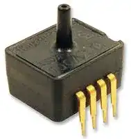
Pressure Sensor, ASDX Series, Silicon, 30 psi, Analogue, Absolute, 5 V, Axial, 2.5 mA
- Manufacturer: HONEYWELL
- Product type: Pressure Transducers
- Port Style: Axial
- Product Range: ASDX Series
- Sensor Output: Analogue
- Supply Current: 2.5mA
- Voltage Rating: 5V
- Operating Pressure Max: 30psi
- Pressure Measurement Type: Absolute
| Delivery and price | |
|---|---|
| Units per pack | 10 |
| Price | 59.42 € |
| Current stock | 10+ |
| Lead time | 30 days |
## ASDX Series Silicon Pressure Sensors

## **DESCRIPTION**

The ASDX Series is a Silicon Pressure Sensor offering a ratiometric analog interface for reading pressure over the specified full scale pressure span and temperature range.

The ASDX is fully calibrated and temperature compensated for sensor offset, sensitivity, temperature effects and non-linearity using an on-board Application Specific Integrated Circuit (ASIC). Calibrated output values for pressure are updated at approximately 1 kHz.

The standard ASDX is calibrated over the temperature range of 0 °C to 85 °C [32 °F to 185 °F]. The sensor is characterized for operation from a single power supply of either 3.3 Vdc or 5.0 Vdc.

## **FEATURES**

- Ratiometric 12-bit analog output

- Precision ASIC conditioning and temperature compensated over 0 °C to 85 °C [32 °F to 185 °F] temperature range

- Low operating voltage

- Absolute, differential and gage types

- Pressure ranges from 10 inches H20 to 100 psi

These sensors are available to measure absolute, differential and gage pressures. The absolute versions have an internal vacuum reference and an output value proportional to absolute pressure. Differential versions allow application of pressure to either side of the sensing diaphragm. Gage versions are referenced to atmospheric pressure and provide an output proportional to pressure variations from atmosphere.

The ASDX Series sensors are intended for use with noncorrosive, non-ionic working fluids such as air and dry gases. They are designed and manufactured according to standards in ISO 9001.

## **POTENTIAL APPLICATIONS**

   - Flow calibrators

   - Ventilation and air flow monitors

   - Gas flow instrumentation

   - Sleep apnea monitoring and therapy equipment

   - Barometry

   - Pneumatic controls

   - HVAC

- Standard calibrations in inches H20, cm H20, psi, mbar, bar, kPa

- Total error band of ±2.0% of full scale span maximum

- RoHS compliant

## **ASDX Series Silicon Pressure Sensors**

## **Table 1. Absolute Maximum Ratings[1]**

|**Table 1. Absolute Maximum Ratings1**||||
|---|---|---|---|
|**Parameter**|**Min**|**Max**|**Unit**|
|Supply voltage (Vsupply)|-0.3|6.0|Vdc|
|Voltage to any pin|-0.3|Vsupply+ 0.3|Vdc|
|ESD susceptibility (human body model)|3|-|kV|
|Storage temperature|-50 [-58]|125 [257]|°C [°F]|
|Lead temperature (2 s to 4 s)<br>|-|250 [482]|°C [°F]|
|External capacitance between Vsupplyandground~~2~~|100|470|nF|


## **Table 2. Operating Specifications**

|**Table 2. Operating Specifications**|||||
|---|---|---|---|---|
|**Parameter**<br>|**Min.**|**Typ.**|**Max.**|**Unit**|
|Supply voltage: (Vsupply)~~3~~<br>3.3 Vdc<br>5.0 Vdc<br>_Sensors are either 3.3 Vdc or 5.0 Vdcper the orderguide(see Figure 1)._|3.0<br>4.75|3.34<br>5.04|3.6<br>5.25|Vdc|
|Supply current<br>|1.5|2.5|3.5|mA|
|Compensated temperaturerange~~5~~<br>|0 [32]|-|85 [185]|°C [°F]|
|Operating temperaturerange~~6~~<br>|-20 [-4]|-|105 [221]|°C [°F]|
|Overpressure~~7~~<br>|2Xoperating pressurerangeminimum||||
|Burst pressure~~8~~|3Xoperating pressurerangeminimum||||
|Startup time (powerup to dataready)|-|-|5|ms|
|Response time|-|1.0|-|ms|
|Upperoutput clippinglimit|97.5|-|-|Vsupply|
|Loweroutput clippinglimit|-|-|2.5|Vsupply|
|Minimum loadresistance<br>|5.0|-|-|kOhm<br>|
|Totalerrorband~~9~~|-|-|2.0|%FSS~~10~~|
|Output resolution|12|-|-|bits|


## **Table 3. Environmental Specifications**

|**Table 3. Environmental Specifications**||
|---|---|
|**Parameter **|**Characteristic**|
|Humidity|0% to 95%RH non-condensing|
|Vibration|10 G at20Hzto2000Hz|
|Shock|100 Gfor 11 ms|
|Life|1 million cycles minimum|


## **Table 4. Wetted Materials[11]**

|**Table 4. Wetted Materials11**|||
|---|---|---|
|**Parameter **|**Port 1(Pressure Port)**~~**12**~~|**Port 2(Reference Port)**~~**12**~~|
|Covers|glass-filledPBT|glass-filledPBT|
|Adhesives|silicone|silicone and epoxy|
|Electronic components|silicon andglass|silicon, glass,andgold|


## **Notes:**

1. Absolute maximum ratings are the extreme limits that the device will withstand without damage to the device.

2. An external bypass capacitor is **required** across the supply voltage (Pins 1 and 3 – see Figure 4) as close to the sensor supply pin as possible for correct sensor operation.

3. Ratiometricity of the sensor (the ability of the output to scale to the input voltage) is achieved within the specified operating voltage for each option. Other custom supply voltages are available, please contact Honeywell Customer Service.

4. The sensor is not reverse polarity protected. Incorrect application of excitation voltage or ground to the wrong pin may cause electrical failure.

5. The compensated temperature range is the temperature range (or ranges) over which the sensor will produce an output proportional to pressure within the specified performance limits.

6. The operating temperature range is the temperature range over which the sensor will produce an output proportional to pressure but may not remain within the specified performance limits.

7. Overpressure is the maximum pressure which may safely be applied to the product for it to remain in specification once pressure is returned to the operating pressure range. Exposure to higher pressures may cause permanent damage to the product.

8. Burst pressure is the maximum pressure that may be applied to any port of the product without causing escape of pressure media. Product should not be expected to function after exposure to any pressure beyond the burst pressure.

9. Total error band is the maximum deviation in output from ideal transfer function over the entire compensated temperature and pressure range. Includes all errors due to offset, full scale span, pressure non-linearity, pressure hysteresis, repeatability, thermal effect on offset, thermal effect on span and thermal hysteresis. Specification units are in percent of full scale span (%FSS).

10. Full scale span (FSS) is the algebraic difference between the output signal measured at the maximum (Pmax.) and minimum (Pmin.) limits of the pressure range.

11. Consult Honeywell Customer Service for detailed material information.

12. For AC pressure port configuration, the “pressure” and “reference” ports are reversed.

2 sensing.honeywell.com

## **Figure 1. Nomenclature and Order Guide**

**==> picture [420 x 448] intentionally omitted <==**

**----- Start of picture text -----**<br>
Package Selection [13] Calibration Selection<br>es<br>ASDX _ _ X _ _ _ _ _  o A _ e _<br>Series<br>Power Supply Voltage<br>3  = 3.3 Vdc<br>5  = 5.0 Vdc<br>Pressure Port<br>Transfer Function Limits [14]<br>AV  = Axial port on top, vented cover on bottom AB  = 10% to 90% calibration = 5% to 95% calibration<br>Output Type [15]<br>A  = Analog voltage<br>Pressure Range [16, 17, 18]<br>  Gage  Differential   Absolute<br>RR  = Radial port on top, radial port on bottom<br>-  005ND =  ±5 in H2O -<br>010NG  = 10 in H2O 010ND =  ±10 in H2O -<br>- 015CD =  ±15 cm H2O -<br>025CG  = 25 cm H2O 025CD =  ±25 cm H2O -<br>001PG  = 1 psi 001PD  = ±1 psi -<br>005PG  = 5 psi 005PD  = ±5 psi -<br>015PG  = 15 psi 015PD  = ±15 psi 015PA  = 15 psi<br>AC           for absolute)= Axial port, sealed cover (commonly used 030PG100PG  = 30 psi = 100 psi 030PD-  = ±30 psi 030PA100PA  = = 100 psi30 psi<br>- 015MD  = ±15 mbar -<br>025MG  = 25 mbar 025MD  = ±25 mbar -<br>050MG  = 50 mbar 050MD  = ±50 mbar -<br>100MG  = 100 mbar 100MD  = ±100 mbar -<br>200MG  = 200 mbar 200MD  = ±200 mbar -<br>500MG  = 500 mbar 500MD  = ±500 mbar -<br>001BG  = 1 bar 001BD  = ±1 bar 001BA  = 1 bar<br>RV  = Radial port, single 002BG  = 2 bar 002BD  = ±2 bar 002BA  = 2 bar<br>007BG  = 7 bar - 007BA  = 7 bar<br>003KG  = 3 kPa 003KD  = ±3 kPa -<br>004KG  = 4 kPa 004KD  = ±4 kPa -<br>005KG  = 5 kPa 005KD  = ±5 kPa -<br>010KG  = 10 kPa 010KD  = ±10 kPa -<br>020KG  = 20 kPa 020KD  = ±20 kPa -<br>050KG  = 50 kPa 050KD  = ±50 kPa -<br>100KG  = 100 kPa 100KD  = ±100 kPa 100KA  = 100 kPa<br>200KG  = 200 kPa 200KD  = ±200 kPa 200KA  = 200 kPa<br>700KG  = 700 kPa - 700KA  = 700 kPa<br>Future Option<br>**----- End of picture text -----**<br>


## **Notes:**

13. Other package combinations are possible, please contact Honeywell Customer Service.

14. The transfer function limits define the output of the sensor at a given pressure input. By specifying the output signal at the maximum (Pmax.) and minimum (Pmin.) limits of the pressure range, the complete transfer curve for the sensor is defined. See Figure 2 for a graphical representation of each calibration.

15. For a digital output, please refer to the ASDX Digital Series.

16. Custom pressure ranges are available, please contact Honeywell Customer Service.

17. The pressure units (inches H20, cm H20, psi, mbar, bar, kPa) define the units used during calibration and in the application.

18. See Table 5 for an explanation of sensor types.

Honeywell Sensing and Control

3

## **ASDX Series Silicon Pressure Sensors**

**Table 5. Sensor Types**

|~~|~~||
|---|---|
|**Type**<br>~~|~~|**Description **|
|Absolute<br>~~|~~|Output is proportional to difference between applied pressure and built-in reference to vacuum (zero pressure).|
|Gage<br>~~|~~|Output is proportional to difference between applied pressure and atmospheric (ambient) pressure.|
|Differential<br>~~|~~|Output isproportional to difference betweenpressure applied to each of thepressureports(Port 1 – Port 2).|


## **Figure 2. Transfer Functions and Limits**

**==> picture [370 x 9] intentionally omitted <==**

**----- Start of picture text -----**<br>
A Calibration, 10% to 90%   B Calibration, 5% to 95%<br>**----- End of picture text -----**<br>


## **Figure 3. Completed Catalog Listing Example**

**ASDXAVX001PGAA3: ASDXAV001PGAA3 Output vs. Pressure** AV pressure port, 1 psi gage, analog 100 _ output, 10% to 90% calibration at 3.3 Vdc operation.

4 sensing.honeywell.com

**==> picture [371 x 24] intentionally omitted <==**

**----- Start of picture text -----**<br>
Figure 4. Dimensional Drawings (For reference only: mm [in].)<br>AV Package (Legacy G2)  RR Package (Legacy D4)<br>**----- End of picture text -----**<br>


**AC Package (Legacy A2)**

**RV Package**

**Table 7. Pinout**

|**Pin**|**Definition**|**Type**|**Description**|
|---|---|---|---|
|1|Vsupply|supply|powersupply source|
|2|Vout|analog output|provides the analog output|
|3|GND|supply|powersupply ground|
|4|N/C|not used|do not connect in the application|
|5|N/C|not used|donot connectinthe application|
|6|N/C|not used|do not connect in the application|
|7|N/C|not used|donot connectinthe application|
|8|N/C|not used|do not connect in the application|


Honeywell Sensing and Control 5

## **[WARNING ]**

## **PERSONAL INJURY**

DO NOT USE these products as safety or emergency stop devices or in any other application where failure of the product could result in personal injury.

**Failure to comply with these instructions could result in death or serious injury.**

## **WARRANTY/REMEDY**

Honeywell warrants goods of its manufacture as being free of defective materials and faulty workmanship. Honeywell’s standard product warranty applies unless agreed to otherwise by Honeywell in writing; please refer to your order acknowledgement or consult your local sales office for specific warranty details. If warranted goods are returned to Honeywell during the period of coverage, Honeywell will repair or replace, at its option, without charge those items it finds defective. **The foregoing is buyer’s sole remedy and is in lieu of all other warranties, expressed or implied, including those of merchantability and fitness for a particular purpose. In no event shall Honeywell be liable for consequential, special, or indirect damages.**

## **[WARNING ]**

## **MISUSE OF DOCUMENTATION**

- The information presented in this product sheet is for reference only. Do not use this document as a product installation guide.

- Complete installation, operation, and maintenance information is provided in the instructions supplied with each product.

**Failure to comply with these instructions could result in death or serious injury.**

## **SALES AND SERVICE**

Honeywell serves its customers through a worldwide network of sales offices, representatives and distributors. For application assistance, current specifications, pricing or name of the nearest Authorized Distributor, contact your local sales office or:

**E-mail:** info.sc@honeywell.com

- **Internet:** sensing.honeywell.com

## **Phone and Fax:**

While we provide application assistance personally, through our literature and the Honeywell web site, it is up to the customer to determine the suitability of the product in the application.

Asia Pacific +65 6355-2828; +65 6445-3033 Fax Europe +44 (0) 1698 481481; +44 (0) 1698 481676 Fax Latin America +1-305-805-8188; +1-305-883-8257 Fax USA/Canada +1-800-537-6945; +1-815-235-6847 +1-815-235-6545 Fax

Specifications may change without notice. The information we supply is believed to be accurate and reliable as of this printing. However, we assume no responsibility for its use.

Sensing and Control Honeywell 1985 Douglas Drive North Golden Valley, MN 55422 **sensing.honeywell.com**

008090-12-EN IL50 July 2014 Copyright © 2014 Honeywell International Inc. All rights reserved.
Updated at February 9, 2023
Honeywell is a globally recognized leader in the design and manufacture of advanced sensing and switching solutions. Renowned for engineering components that deliver enhanced precision and ruggedness, Honeywell provides essential technologies for demanding applications across critical healthcare, aerospace, and industrial equipment. With a comprehensive portfolio built to address both basic and complex design challenges, the company stands at the forefront of reliable electronic component manufacturing. The core of our Honeywell offering is an extensive selection of high-performance sensors and transducers. This includes a robust lineup of pressure sensors and transducers engineered for accurate fluid and gas measurement in challenging environments. Furthermore, we provide a wide array of temperature sensors and specialized temperature sensing NTC thermistors designed for stable thermal management, alongside precision current sensors and load cells that deliver critical feedback for control systems. Beyond advanced sensing technology, Honeywell’s expertise extends to essential circuit protection and electromechanical components. Our selection encompasses power relays, thermal magnetic circuit breakers, and standard terminal blocks, ensuring safe and efficient power distribution. Whether integrating core components or sourcing specialized accessories, design engineers can rely on Honeywell for uncompromising quality and operational excellence.
About Novapart
Novapart is a B2B electronic component broker specialising in stock shortages and cost reduction. We source hard-to-find parts and identify compliant alternatives across a catalogue of 410,000+ components from 500+ manufacturers.
Learn more →Stock Shortage Specialist
When a component is unavailable, discontinued or has an unacceptable lead time, we tap into our network of vetted European and Asian distributors to source what you need — without compromising on quality or traceability.
Request a quote →Compliant Alternatives
We identify pin-to-pin, electrically equivalent substitutes that meet the same certifications (RoHS, AEC-Q100, REACH) as your original specification — validated against datasheets, not just part numbers. Often at a lower cost.
BOM Analysis service →