
Image not available
Illustrative purposes only

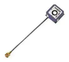
AP.10F.07.0039B
RF Antenna, Patch, 1.575 GHz, Right Hand Circular, I-Pex Connector, 15 dBi, 2 VSWR
⚠️ Reference pricing provided. In case of supply shortages, we will connect you with our trusted procurement partners to ensure your project's continuity.
- Manufacturer: TAOGLAS
- Product type:
- Gain: 15dBi
- SVHC: To Be Advised
- VSWR: 2
- Input Power: -
- Antenna Type: Patch
- Frequency Max: 1.575GHz
- Frequency Min: -
- Product Range: -
- Input Impedance: -
- Antenna Mounting: I-Pex Connector
- Antenna Polarisation: Right Hand Circular
| Delivery and price | |
|---|---|
| Units per pack | 250 |
| Price | 7.95 € |
| Current stock | 10+ |
| Lead time | 30 days |
Datasheet

## **SPECIFICATION** - Part No. : AP.10F.07.0039B Product Name : 2 Stage 25dB 10mm Active GPS/GALILEO Ceramic Patch Antenna 39mm 0.81 Micro Coax with IPEX MHFI (U.FL compatible) with Front End SAW Filter Feature : Small form factor GPS active patch 10mm*10mm*4mm, Wide Voltage 1.8V~5.5V 25dB LNA High performance Ultra Low Power Consumption RoHS Compliant Page 1 of 10 SPE-12-8-004/B/SS ## **1. Introduction** The AP.10F active GPS/GALILEO patch antenna is the smallest GPS/GALILEO high performance antenna currently available in the world. It uses an extremely sensitive high dielectric constant powder formulation and tight process control and patented circular polarized side stripe design the 10*10*4mm patch antenna. The front end SAW filter reduces the risks where there is a cellular transmitter nearby of interference from out of band frequencies which can cause LNA burn-out, saturation, or radiated spurious emissions. This product is suited to small form factor mobile devices such as GPS Smartphones, Personal Location, Medical devices, Telematic devices and Automotive navigation and tracking. Custom gain, connector and cable versions are available. Custom tuning is available for specific customer device environments and is dependent on a minimum order quantity and NRE in some cases. Please contact regional sales office for details. The AP.10E consists of 2 functional blocks – the LNA and also the patch antenna. Page 2 of 10 SPE-12-8-004/B/SS ## **2. Specification** |ANTENNA<br>~~ae~~|ANTENNA<br>~~ae~~|ANTENNA<br>~~ae~~|ANTENNA<br>~~ae~~|ANTENNA<br>~~ae~~| |---|---|---|---|---| |Frequency||1575.42 ± 1.023MHz||| |Gain @ Zenith||-10dBic Typ. @ Zenith||| |Polarization||RHCP||| |Axial Ratio||4.0dB max. @Zenith||| |Patch Dimension||10*10*4.0mm||| |LNA<br>~~ae~~||||| |Frequency|1575.42 ± 1.023MHz<br>F0=1575.42MHz|||| |Outer Band<br>Attenuation|F030MHz<br>5dB min.<br>F050MHz 20dB min.<br>F0100MHz 25dB min.|||| |Output Impedance|50Ω|||| |Output VSWR|2.0 Max|||| |Pout at 1dB Gain<br>Compression point|Typ. 11 dBm<br>Min. 8 dBm|||| |LNA Gain, Power Consumption and Noise Figure||||| |Voltage|LNA Gain<br>(Typ)||Power Consumption(mA)<br>Typ|Noise<br>Figure<br>Typ| |Min. 1.8V|20dB||5mA|2.7dB| |Typ. 3.0V|25dB||10mA|2.5dB| |Max. 5.5V|25dB||23mA|2.7dB| Page 3 of 10 SPE-12-8-004/B/SS |CABLE AND CONNECTOR<br>_LEL—okEL—h—nL--|CABLE AND CONNECTOR<br>_LEL—okEL—h—nL--| |---|---| |RF Cable|Coaxial CableØ0.81 ± 0.1mm, length 39 ± 2.0mm| |Connector|IPEX MHFI (U.FL)| |ANTENNA, LNA, CABLE AND CONNECTOR<br>~~LEE~~|| |Frequency|1575.42 ± 1.023MHz| |Gain|At 3V: 154dBic@90| |Output Impedance|50Ω| |Polarization|RHCP| |Output VSWR|Max 2.0| |Operation<br>Temperature|-40°C to + 85°C| |Storage Temperature|-40°C to + 105°C| |Relative Humidity|40% to 95%| |Input Voltage|Min:1.8V Typ. 3.0V Max:5.5V| |Antenna|10*10*4mm| Page 4 of 10 SPE-12-8-004/B/SS ## **3. LNA Gain and Out Band Rejection @3.0V** Page 5 of 10 SPE-12-8-004/B/SS ## **4. LNA Noise Figure @3.0V** Page 6 of 10 SPE-12-8-004/B/SS ## **XZ Plane Radiation** ## **YZ Plane Radiation** ## **XY Plane Radiation** Page 7 of 10 SPE-12-8-004/B/SS ## **5. Antenna Drawing** Page 8 of 10 SPE-12-8-004/B/SS ## **6. Plugs Usage Precautions** ## **6.1. Mating / unmating** (1) To disconnect connectors, insert the end portion of I-PEX under the connector flanges and pull off vertically, in the direction of the connector mating axis. (2) To mate the connectors, the mating axes of both connectors must be aligned and the connectors can be mated. The "click" will confirm fully mated connection. Do not attempt to insert on an extreme angle. ## **6.2. Pull forces on the cable after connectors are mated** After the connectors are mated, do not apply a load to the cable in excess of the values indicated in the diagram below. Page 9 of 10 SPE-12-8-004/B/SS ## **7. Packaging** Taoglas makes no warranties based on the accuracy or completeness of the contents of this document and reserves the right to make changes to specifications and product descriptions at any time without notice. Taoglas reserves all rights to this document and the information contained herein. Reproduction, use or disclosure to third parties without express permission is strictly prohibited. Copyright © Taoglas Ltd. Page 10 of 10 SPE-12-8-004/B/SS
Updated at June 9, 2026
About Novapart
Novapart is a B2B electronic component broker specialising in stock shortages and cost reduction. We source hard-to-find parts and identify compliant alternatives across a catalogue of 410,000+ components from 500+ manufacturers.
Learn more →Stock Shortage Specialist
When a component is unavailable, discontinued or has an unacceptable lead time, we tap into our network of vetted European and Asian distributors to source what you need — without compromising on quality or traceability.
Request a quote →Compliant Alternatives
We identify pin-to-pin, electrically equivalent substitutes that meet the same certifications (RoHS, AEC-Q100, REACH) as your original specification — validated against datasheets, not just part numbers. Often at a lower cost.
BOM Analysis service →