
Image not available
Illustrative purposes only

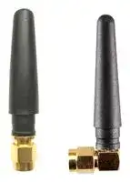
ANT-MSTUBR-SMAM
Stubby Antenna, 2.17GHz, 3 VSWR, 3dBi Gain, SMA Connector
⚠️ Reference pricing provided. In case of supply shortages, we will connect you with our trusted procurement partners to ensure your project's continuity.
- Manufacturer: RF SOLUTIONS
- Product type:
- Antenna Type:Stubby; Frequency Min:880MHz; Frequency Max:2170MHz; Antenna Mounting:SMA Connector; Gain:3dBi; VSWR:3; Input Power:-; Input Impedance:50ohm; Antenna Polarisation:-; Produ
- Gain: 3dBi
- SVHC: No SVHC (25-Jun-2025)
- VSWR: 3
- Input Power: -
- Antenna Type: Stubby
- Frequency Max: 2170MHz
- Frequency Min: 880MHz
- Product Range: -
- Input Impedance: 50ohm
- Antenna Mounting: SMA Connector
- Antenna Polarisation: -
| Delivery and price | |
|---|---|
| Units per pack | 250 |
| Price | 3.9 € |
| Current stock | 10+ |
| Lead time | 30 days |
Datasheet

-

-

-

-

-

- `Ω`

-

-

-

-

-

-

ANT-MSTUB Antenna oo

ext

## Mechanical Detail—Straight Version

**==> picture [442 x 588] intentionally omitted <==**

**----- Start of picture text -----**<br>
a ~<br>—_ bh<br>Data — VSWR VSWR<br>9 Nov 2669 89:48:46<br>(CHd] REL SHR 1 ARE od 32.7455 1 998.686 666 MHz<br>ud | || CH1 Markers<br>.99 |GHz | | aftBoRTR<br>FeaeSHE<br>1.71886 GHz<br>4: 2.17608<br>2.176608 GHz<br>|<br>| |<br>|<br>! a }<br>|<br>START 566,688 666 MHz STOP 2 506,066 888 MHz<br>**----- End of picture text -----**<br>


## Performance Data — VSWR VSWR

ANT-MSTUB-1

www.'fsolutions.co.uk

## ANT-MSTUB Antenna

**==> picture [50 x 50] intentionally omitted <==**

**----- Start of picture text -----**<br>
on<br>axe<br>**----- End of picture text -----**<br>


## Performance Data — RETURN LOSS

**==> picture [506 x 589] intentionally omitted <==**

**----- Start of picture text -----**<br>
Frequency<br>(MHz)<br>Ee<br>960 | oz | 52 | 206 | tse | toto | aa<br>imo | 189 | 1009 | 62 | oes | tat | 339<br>100 | 079 | 860 | 260 | 1.20 | 1302 | 230<br>10 | tte | 093 | asa | tos | tts | 298<br>go<br>— 824MHz<br>120 -{ 60 |——ssomHz a0 T7ioMMe<br>° eX ed 120 = 60 —— 1800MHz<br>-10 PX Oe CAN LER —— 1880MHz<br>* 150 Vl, Os ay aN 30 “ Ww — 1990MHz<br>he a “ x 7 - WN \ ‘ we 150 f Va < vane — X - S\ \\ 30<br>-25 : by eA i -30 4 180 SaERGREEE: “En EREE, Jitg<br>mi on ean \ YY * oe } | (i Mi eA h} ae<br>“10 are eee ee Zo yf gp F380 “an 210% \N a nee SAD / 7330<br>Q 240 = ae eee = 300 7 240 San<br>270 270<br>in<br>go — 1710MHz<br>—— 824MHz 120 a 80 — 1800MHz<br>a<br>po 80 —— 880MHz 5 Va a-=-}enp ~~ — 1880MHz<br>-6 = =o —— 960MHz . y Caio —— 1990MHz<br>“ if i 7 ra AC. 2 a ‘ ae \ “28 } { i i ~ NTx a oO : \ : \ i :<br>-26 i \ A ye \ ‘, 4 aT Z .< va / / { | -20 \ i i i oa ns an<br>-15 “ Nea a el y Ay -10 Re a LIU<br>5 ae SSE \7 8 240 S800<br>0 m0 Se 00 270<br>270<br>**----- End of picture text -----**<br>


ANT-MSTUB-1

www.'fsolutions.co.uk

ANT-MSTUB Ant ntenna —S———S—e==ee&sj=axC@Cuunaeeee eee. ,

aXeeo ea

## Performance Data

|Total|Frequency|(MHz)|824|960|1710|1990|2170|
|---|---|---|---|---|---|---|---|
||Point Values|||||||
|||Ant. Port Input Pwr. (dBm)|0|0|0|0|0|
|||Tot. Rad. Pwr. (dBm)|-3.02158|-4.53846|-3.43015|-3.35456|-2.55152|
|||Peak EIRP (dBm)|_—-0.273484|-2.20475|-0.31156|—-0.177191|0.578211|
|||Directivity (dBi)|2.7481|2.33372|3.11859|3.17737|3.12973|
|||Efficiency (dB)|-3.02158|-4.53846|-3.43015|-3.35456|-2.55152|
|||Efficiency (%)|49.8703|35.1685|45.3925|46.1896|55.571|
|||Gain (dBi)|—_-0.273484|-2.20475|-0.31156|—-0.177191|0.578211|
|||NHPRP i/4 (dBm)|-4.7446|-~6.37139|-4.52182|-4.23522|-3.53953|
|||NHPRP i/6 (dBm)|-6.34653|-7.99471|-5.92586|-5.58046|-4.96417|
|||NHPRP i/8 (dBm)|-7.517|-9.23127|-7.02402|-6.7178|-~6.12253|
|||Upper Hem. PRP (dBm)|-5.74067|-7.0721|-5.69479|-6.16282|-4.67429|
|||Lower Hem. PRP (dBm)|-6.34403|-8.08427|-7.34124|-6.57675|-6.67857|
|||NHPRP4 /TRP Ratio (dB)|-1,72302|-1.83292|-1.09167|-0.880662|_—-0.988006|
|||NHPRP4 /TRP Ratio (%)|67.2509|65.5704|77.7738|81.6458|79.6525|
|||Near Horz. TRP for i/4 (dBm)|-3.23945|-4.86624|-3.01667|-2.73007|-2.03438|
|||NHPRP6 /TRP Ratio (dB)|-3.32495|-3.45624|-2.49571|-2.2259|-2.41265|
|||NHPRP6 /TRP Ratio (%)|46.5055|45.1207|56.2897|59.8977|57.3767|
|||Near Horz. TRP for i/6 (dBm)|-3.33623|-4.98441|-2.91556|-2.57016|-1.95387|
|||NHPRP8 /TRP Ratio (dB)|-4.49542|-4.69281|-3.59387|-3.36324|-3.57101|
|||NHPRP8 /TRP Ratio (%)|35.5188|33.9406|43.7133|46.0974|43.9439|
|||Near Horz. TRP for i/8 (dBm)|-3.34539|-5.05967|-2.85242|-2.54619|-1.95093|
|||UHPRP /TRP Ratio (dB)|-2.71909|-2.53364|-2.26463|-2.80827|-2.12277|
|||UHPRP /TRP Ratio (%)|53.4676|55.8003|59.3659|52.381|61.3371|
||Upper Hem.Total Radiated Pwr(dBm)||-2.73037|-4.0618|-2.68449|-3.15252|-1.66399|
|||LHPRP /TRP Ratio (dB)|-3.32245|-3.5458|-3.91109|-3.22219|-4.12705|
|||LHPRP /TRP Ratio (%)|46.5324|44.1997|40.6341|47.619|38.6629|
||Lower Hem. Total Radiated Pwr(dBm)||-3.33373|-5.07397|-4.33094|-3.56645|-3.66827|
|||Front/Back Ratio (dB)|2.08198|2.04379|5.71434|2.40834|5.19069|
|||Phi BW (?|282|125|194|151|238|
|||+PhiBW(?|63|61|138|112|103|


ee ANT-MSTUB-1 www.'fsolutions.co.uk

## ANT-MSTUB Antenna

**==> picture [54 x 41] intentionally omitted <==**

**----- Start of picture text -----**<br>
oxsoe<br>**----- End of picture text -----**<br>


**==> picture [5 x 5] intentionally omitted <==**

**----- Start of picture text -----**<br>
.y<br>**----- End of picture text -----**<br>


**==> picture [441 x 401] intentionally omitted <==**

**----- Start of picture text -----**<br>
||||||||||
|---|---|---|---|---|---|---|---|---|
|"ot eS|824|960|1710|1990|2170|
|rr|ee|ee|
|- Phi BW|°|219|64|56|39|135|
|Theta BW|°|107|||304|||122|115|82|
|+ Th. BW|Q|50|204|87|72|58|
|- Th. BW °|7|100|35|43|24|
|Boresight Phi 0|33.65|53.4|304.1|42.05|56.7|
|Boresight Th. °|45|60|60|75|45|
|Maximum|Power|(dBm)|-0.273484|-2.20475|-0.31156|-0.177191|0.578211|
|Minimum|Power|(dBm)|-15.3831|-20.1007|-16.2884|-15.7609|-14.7237|
|Average|Power|(dBm)|-2.7917|-4.2109|-4.0649|-4.32296|-3.55684|
|Max/Min|Ratio (a8)|15.1096|17.896|15.9768|15.5837|15.3019|
|Max/Avg|Ratio (a8)|2.61822|2.00615|3.75334|4.14577|4.13505|
|Min/Avg|Ratio (a8)|12.5914|“15.8898|-12.2235|-11.4379|-11.1669|
|Average Gain (a8)|-3.021 58|“4.53846|-3.43015|-3.35456|-2.55152|
|E-Plane BW (?|||87|||102|||191|102|84|
|+ E-Plane BW|°|46|64|142|54|22|
|- E-Plane BW|°|41|||38|49|48|62|
|H-Plane BW|°|360|360|97|81|102|
|+ H-Plane BW|°|360|360|51|36|57|
|- H-Plane BW ag|0|0|46|45|45|

**----- End of picture text -----**<br>


a ANT-MSTUB-1 www.tfsolutions.co.uk

ANT-MSTUB Antenna oo

**==> picture [53 x 40] intentionally omitted <==**

**----- Start of picture text -----**<br>
ext<br>**----- End of picture text -----**<br>


## 6. Measurement Setup

## (1) Reflection Coefficient Measurement -

## (a) Instrument : Network Analyzer

- (b) Setup :

   - (1) Calibrate the Network Analyzer by one port calibration using O.S.L calibration kits.

   - (Il) Connect the antenna under test to the Network Analyzer.

   - (Ill) Measure the S11(reflection coefficient) shown in Fig. 1.

(IV) Generally, the S11 is less than - 10dB to ensure the 90% power into antenna and only less than 10% power back to system

**==> picture [107 x 76] intentionally omitted <==**

**----- Start of picture text -----**<br>
| Network Analyzer<br>“port 1<br>**----- End of picture text -----**<br>


## (2) Pattern measurement

:

- a . The anechoic chamber is a far-field measurement system with size of 7Mx3.3mx3.3m. The quiet zone region is 30cm x 30cm x 30cm in the center of the rotator.

**==> picture [404 x 178] intentionally omitted <==**

**----- Start of picture text -----**<br>
OO NNN SONS SNS<br>< asStandard probe antenna Antenna under test ><br>ch }A 4.35m — °<br>STown / QO stepepP RotatorRotator 4 SN><br>Network Analyzer<br>Measure S21 to calculate<br>Gain and Pattern<br>**----- End of picture text -----**<br>


Fig.2 The interior components of the anechoic chamber

ANT-MSTUB-1

www.'fsolutions.co.uk

## ANT-MSTUB Antenna

**==> picture [53 x 44] intentionally omitted <==**

**----- Start of picture text -----**<br>
ext<br>“A<br>**----- End of picture text -----**<br>


- b . The probing antenna is the BBHA 9120 LFA 700MHz ~ 6GHz module (9120D horn antenna),

   - which is placed in the one side of the chamber room. And the antenna under testing (AUT) is placed in the other side of the chamber. The distance between the probing antenna and the AUT is about 4m.

- c.While we measure the radiation patterns by rotating AUT with 360 degrees and repeat again by replacing the AUT with the standard gain antenna under test, we compare both data and using a formula to obtain the gain of AUT. The standard gain antenna is a gain horn (BBHA 9120 LFA 700MHz~6GHZ).

Gyur = Gotanad + Paur ~ Prtana

Gyyp :Gain of AUT Going .Gain of Standard Gain Antenna Pjyp 1 Measured Power of AUT Pang 1 Measured Power of Standard Gain Antenna

- d . The scanning method is CW wave with 6 degree by one step.

- e . We measure the radiation pattern in the free space situation at the lowest, middle and highest frequency for the H(X—Y) + E1(Y—Z) planes, which defined in figure next page.

(3) Plane definition :

**==> picture [371 x 193] intentionally omitted <==**

**----- Start of picture text -----**<br>
|__|<br>Zz z<br>A<br>90 =a) 90<br>H-Plane E1-Plane<br>**----- End of picture text -----**<br>


Fig.3 The plane definition for H and E1 planes.

ANT-MSTUB-1

www.'fsolutions.co.uk

Whilst the information in this document is believed to be correct at the time of issue, RF Solutions Ltd does not accept any liability whatsoever for its accuracy, adequacy or completeness. No express or implied warranty or representation is given relating to the information contained in this document. RF Solutions Ltd reserves the right to make changes and improvements to the product(s) described herein without notice.  Buyers and other users should determine for themselves the suitability of any such information or products for their own particular requirements or specification(s).  RF Solutions Ltd shall not be liable for any loss or damage caused as a result of user’s own determination of how to deploy or use RF Solutions Ltd’s products.  Use of RF Solutions Ltd products or components in life support and/or safety applications is not authorised except with express written approval. No licences are created, implicitly or otherwise, under any of RF Solutions Ltd’s intellectual property rights. Liability for loss or damage resulting or caused by reliance on the information contained herein or from the use of the product (including liability resulting from negligence or where RF Solutions Ltd was aware of the possibility of such loss or damage arising) is excluded. This will not operate to limit or restrict RF Solutions Ltd’s liability for death or personal injury resulting from its negligence.
Updated at June 9, 2026
About Novapart
Novapart is a B2B electronic component broker specialising in stock shortages and cost reduction. We source hard-to-find parts and identify compliant alternatives across a catalogue of 410,000+ components from 500+ manufacturers.
Learn more →Stock Shortage Specialist
When a component is unavailable, discontinued or has an unacceptable lead time, we tap into our network of vetted European and Asian distributors to source what you need — without compromising on quality or traceability.
Request a quote →Compliant Alternatives
We identify pin-to-pin, electrically equivalent substitutes that meet the same certifications (RoHS, AEC-Q100, REACH) as your original specification — validated against datasheets, not just part numbers. Often at a lower cost.
BOM Analysis service →