
Image not available
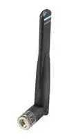
Illustrative purposes only

ANT-DB1-RAF-RPS
RF Antenna, 5.925 to 7.125GHz, WiFi/WLAN/Bluetooth/ZigBee/ISM/IoT, 4.8dBi, 50 ohm, Linear
⚠️ Reference pricing provided. In case of supply shortages, we will connect you with our trusted procurement partners to ensure your project's continuity.
- Manufacturer: TE CONNECTIVITY - LINX
- Product type:
- Gain: 4.8dBi
- SVHC: Lead (21-Jan-2025)
- VSWR: 6.1
- Input Power: 5W
- Antenna Type: WiFi / WLAN / Bluetooth / ZigBee / ISM / IoT
- Frequency Max: 7.125GHz
- Frequency Min: 5.925GHz
- Product Range: RAF Series
- Input Impedance: 50ohm
- Antenna Mounting: RP SMA Connector
- Antenna Polarisation: Linear
| Delivery and price | |
|---|---|
| Units per pack | 100 |
| Price | 12.48 € |
| Current stock | 10+ |
| Lead time | 30 days |
Datasheet

## **ANT-DB1-RAF Hinged Blade WiFi 6/5/4 Antenna**

The ANT-DB1-RAF is a dipole, blade-style antenna for WiFi 6/5/4 applications in the 2.4 GHz and 5 GHz bands and WiFi 6E in the 6 GHz band.

The hinged design allows for the antenna to be positioned for optimum performance and reduces the potential for damage from impact compared to a fixed whip design. The ANT-DB1-RAF antenna is available with an SMA plug (male pin), or RP-SMA plug (female socket) connector.

## **APPLICATIONS**

## **FEATURES**

   - WiFi/WLAN coverage

- Performance at 2.4 GHz to 2.485 GHz

   - WiFi 6E (802.11ax)

- VSWR: ≤ 1.8

- Peak Gain: 4.1 dBi

- – Efficiency: 76%

   - WiFi 6 (802.11ax)

   - WiFi 5 (802.11ac)

   - WiFi 4 (802.11n)

- Performance at 5.150 GHz to 5.850 GHz

         - 802.11b/g

   - VSWR: ≤ 1.7

   - Peak Gain: 5.1 dBi

   - – Efficiency: 94% – Bluetooth®

      - 2.4 GHz ISM applications

- Compact size – Height: 103.7 mm (4.08 in)

      - ZigBee®

   - U-NII bands 1-8

- Diameter: 11.2 mm (0.44 in)

   - Internet of Things (IoT) devices

- Rotating hinge design with detents for straight, 45 degree and 90 degree positioning

   - Smart Home networking

      - Sensing and remote monitoring

      - Wireless vending

- SMA plug (male pin) or RP-SMA plug (female socket) connection

- Security

## **ORDERING INFORMATION**

|Part Number|Description|
|---|---|
|ANT-DB1-RAF-SMA|WiFi 6/WiFi 6E blade-style antenna with SMA plug (male pin)|
|ANT-DB1-RAF-RPS|WiFi 6/WiFi 6E blade-style antenna with RP-SMA plug (female socket)|


Available from Linx Technologies and select distributors and representatives.

DATA AND DEVICES / ANT-DB1-RAF

## **TABLE 1. ELECTRICAL SPECIFICATIONS**

**==> picture [527 x 118] intentionally omitted <==**

**----- Start of picture text -----**<br>
ANT-DB1-RAF ISM/WiFi WiFi/U-NII 1-3 WiFi 6E<br>Frequency Range 2400 MHz to 2485 MHz 5150 MHz to 5850 MHz 5925 MHz to 7125 MHz<br>VSWR (max.) 1.8 1.7 6.1<br>Peak Gain (dBi) 4.1 5.1 4.8<br>Average Gain (dBi) -1.4 -0.6 -2.0<br>Efficiency (%) 76 94 72<br>Polarization Linear Impedance 50 Ω<br>Radiation Omnidirectional Electrical Type Dipole<br>Wavelength 1/2-wave Max Power 5 W<br>**----- End of picture text -----**<br>


Electrical specifications and plots measured in free space with antenna straight.

## **TABLE 2. MECHANICAL SPECIFICATIONS**

**==> picture [527 x 69] intentionally omitted <==**

**----- Start of picture text -----**<br>
Parameter<br>Connection RP-SMA plug (female socket) or SMA plug (male pin)<br>Dimensions 103.7 mm x Ø11.2 mm (4.08 in x Ø0.44 in)<br>Weight 12.7 g (0.45 oz)<br>Operating Temp. Range -40 °C to +80 °C<br>**----- End of picture text -----**<br>


## **PRODUCT DIMENSIONS**

Figure 1 provides dimensions of the ANT-DB1-RAF antenna. The antenna whip can be tilted 90 degrees, and has a detent at 45 degrees enabling the antenna to be oriented in any direction. The rotating base allows for continuous positioning through 360 degrees even while installed.

**==> picture [460 x 134] intentionally omitted <==**

**----- Start of picture text -----**<br>
103.7 mm Ø11.2 mm<br>(4.08 in) (0.44 in)<br>Full 360° Rotation<br>30.3 mm<br>(1.19 in) 84.6 mm<br>(3.33 in)<br>0°, 45°, 90°<br>**----- End of picture text -----**<br>


Figure 1. ANT-DB1-RAF Antenna Dimensions

## **PACKAGING INFORMATION**

The ANT-DB1-RAF antenna is packaged in a plastic bag in quantities of 50. Bags are placed in cartons of 200. Distribution channels may offer alternative packaging options.

DATA AND DEVICES / ANT-DB1-RAF

2

## **ANTENNA ORIENTATION**

The ANT-DB1-RAF antenna is characterized in two antenna orientations as shown in Figure 2. The free space antenna straight orientation characterizes use of an antenna attached to an enclosure- mounted connector. Although the antenna is a dipole not requiring a ground plane for function, the second characterizaton with an adjacent ground plane (102 mm x 102 mm) provides insight into antenna performance when attached directly to a printed circuit board mounted connector. The two orientations represent the most common end-product use cases.

Straight, Free Space without ground plane

On edge of ground plane, bent 90 degrees

Figure 2. ANT-DB1-RAF Antenna Evaluation Orientations

## **STRAIGHT, FREE SPACE**

The charts on the following pages represent data taken with the antenna in free space, with straight orientation, as shown in Figure 3

Figure 3. ANT-DB1-RAF Antenna Straight, Free Space (Straight)

DATA AND DEVICES / ANT-DB1-RAF

3

## **VSWR**

Figure 4 provides the voltage standing wave ratio (VSWR) across the antenna bandwidth. VSWR describes the power reflected from the antenna back to the radio. A lower VSWR value indicates better antenna performance at a given frequency. Reflected power is also shown on the right-side vertical axis as a gauge of the percentage of transmitter power reflected back from the antenna.

**==> picture [457 x 228] intentionally omitted <==**

**----- Start of picture text -----**<br>
7<br>50<br>6<br>40<br>5<br>30<br>4<br>20<br>3<br>2 10<br>1 0<br>2300 2650 3000 3350 3700 4050 4400 4750 5100 5450 5800 6150 6500 6850 7200<br>Frequency (MHz)<br>24002485 5150 58505925 7125<br>VSWR<br>Reflected Power (%)<br>**----- End of picture text -----**<br>


Figure 4. ANT-DB1-RAF Antenna VSWR, Straight

## **RETURN LOSS**

Return loss (Figure 5), represents the loss in power at the antenna due to reflected signals. Like VSWR, a lower return loss value indicates better antenna performance at a given frequency.

**==> picture [462 x 230] intentionally omitted <==**

**----- Start of picture text -----**<br>
0<br>-5<br>-10<br>-15<br>-20<br>-25<br>-30<br>2300 2650 3000 3350 3700 4050 4400 4750 5100 5450 5800 6150 6500 6850 7200<br>Frequency (MHz)<br>24002485 5150 58505925 7125<br>Return Loss (dB)<br>**----- End of picture text -----**<br>


Figure 5. Return Loss for ANT-DB1-RAF, Straight

DATA AND DEVICES / ANT-DB1-RAF

4

## **PEAK GAIN**

The peak gain across the antenna bandwidth is shown in Figure 6. Peak gain represents the maximum antenna input power concentration across 3-dimensional space, and therefore peak performance, at a given frequency, but does not consider any directionality in the gain pattern.

**==> picture [461 x 230] intentionally omitted <==**

**----- Start of picture text -----**<br>
10<br>5<br>0<br>-5<br>-10<br>-15<br>2300 2650 3000 3350 3700 4050 4400 4750 5100 5450 5800 6150 6500 6850 7200<br>Frequency (MHz)<br>24002485 5150 58505925 7125<br>Peak Gain (dBi)<br>**----- End of picture text -----**<br>


Figure 6. Peak Gain for ANT-DB1-RAF, Straight

## **AVERAGE GAIN**

Average gain (Figure 7), is the average of all antenna gain in 3-dimensional space at each frequency, providing an indication of overall performance without expressing antenna directionality.

**==> picture [461 x 230] intentionally omitted <==**

**----- Start of picture text -----**<br>
10<br>5<br>0<br>-5<br>-10<br>-15<br>2300 2650 3000 3350 3700 4050 4400 4750 5100 5450 5800 6150 6500 6850 7200<br>Frequency (MHz)<br>24002485 5150 58505925 7125<br>Average Gain (dBi)<br>**----- End of picture text -----**<br>


Figure 7. Antenna Average Gain for ANT-DB1-RAF, Straight

DATA AND DEVICES / ANT-DB1-RAF

5

## **RADIATION EFFICIENCY**

Radiation efficiency (Figure 8), shows the ratio of power delivered to the antenna relative to the power radiated at the antenna, expressed as a percentage, where a higher percentage indicates better performance at a given frequency.

**==> picture [462 x 230] intentionally omitted <==**

**----- Start of picture text -----**<br>
100<br>90<br>80<br>70<br>60<br>50<br>40<br>30<br>20<br>10<br>0<br>2300 2650 3000 3350 3700 4050 4400 4750 5100 5450 5800 6150 6500 6850 7200<br>Frequency (MHz)<br>24002485 5150 58505925 7125<br>Efficiency (%)<br>**----- End of picture text -----**<br>


Figure 8. Antenna Radiation Efficiency for ANT-DB1-RAF, Straight

DATA AND DEVICES / ANT-DB1-RAF

6

## **RADIATION PATTERNS**

Radiation patterns provide information about the directionality and 3-dimensional gain performance of the antenna by plotting gain at specific frequencies in three orthogonal planes. Antenna radiation patterns for a straight orientation are shown in Figure 9 using polar plots covering 360 degrees. The antenna graphic above the plots provides reference to the plane of the column of plots below it. Note: when viewed with typical PDF viewing software, zooming into radiation patterns is possible to reveal fine detail.

## **RADIATION PATTERNS - STRAIGHT**

XZ-Plane Gain

YZ-Plane Gain

XY-Plane Gain

## **2400 MHZ TO 2485 MHZ (2450 MHZ)**

**==> picture [462 x 349] intentionally omitted <==**

**----- Start of picture text -----**<br>
35 36 5 1 2 3 35 36 5 1 2 3 35 36 5 1 2 3<br>34 0 4 34 0 4 34 0 4<br>33 -5 5 33 -5 5 33 -5 5<br>31 32 ; Dh“_ <i -10-15-20 = ave X 6 7 31 32 Jo Sy -10-15-20  = 6 7 31 32 MSGFE -10-15-20 6 7<br>-25 -25 -25<br>30 -30 8 30 -30 8 30 -30 8<br>-35 -35 -35<br>29 / Fie 7)] / L hK LX -40 saryTER S Sc\ Y\\\\ \\ 9 29 // f /f’ / / ig // KSLTT -40 \ XX\ \ \ \\ 9 29 fy/, / gen/ Vf s -40 a tayn<~~\., 9<br>-45 -45 -45<br>28 |I]| |T>++TfTra| | | { WIZ SaRSSEELT: -50  i. : | oe\ rTat TY]\| \| \\fi |\} 10 28 ||f iWii||t+tLff[/ [/ ey eesoo -50 y\ \\ yyy) \\ \ \\  \\\4\\ \ \\a 10 28 Py[ if[af //  ty[/// , (KISSKy oa -50 S\\\\ SS \ V\\Vy\’ \ \ \Ve 10<br>27 11 27 11 27 | i yy 11<br>[[WY]] \ VLA iis TTL EHP}<br>26 12 26 12 26 12<br>25 .XK~: eeSeSocaL411ewanesTSneXxoALSA]4 AViaAy Ity/ 13 25 \LY\\i \\\\\ \\\XNTE* SOsVXm GunneeSOTTT iy [wa]  SL [S/d)] / 7] ZyVianIN / 13 | 25 VALW\WAVV\  AAAS\LONVAX NOvannee/LSSLY. /J} /TIE / / 13 |<br>24 14 24 14 24 14<br>23 renee’4OA 15 23 Soe os 15 23 SY rey Ys 15<br>22 16 22 16 22 16 2400 MHz<br>NY 21 20 Af 19 18 17 A Nes 21 20 ~~ 19 a fEVY 18 17 SFs 21 20 19 18 17 J a 2460 MHz2500 MHz<br>XZ-Plane Gain YZ-Plane Gain XY-Plane Gain<br>5150 MHZ TO 5850 MHZ (5500 MHZ)<br>35 36 5 1 2 3 35 36 5 1 2 3 35 36 5 1 2 3<br>34 0 4 34 0 4 34 0 4<br>33 -5 5 33 -5 5 33 -5 5<br>32 -10-15 6 32 BA -10-15  SSIES 6 32 CoS -10-15 6<br>31 : Soames -20 . 7 31 -20 7 31 -20 7<br>-25 -25 Ufa -25 ‘<br>30 -30 8 30 -30 8 30 -30 8<br>WYlowNN -35 She : SX %\ Vyfi.)  =WN -35 aa \ \ [.] \ / SATII -35  TS . \<br>29 -40 9 29 -40 9 29 -40 9<br>-45 -45 -45<br>28 Wee aA -50 /2aeee nant 10 28 LLL LLY Koa -50  \\\\\ \ 10 28 WILLS KAS -50  \\\\ \\ 10<br>27 WELLES SEE T a 11 27 WELLER TTA] 11 27 ees oases | 11<br>26 12 26 12 26 12<br>25 13 25 13 25 13<br>24 14 24 14 24 14<br>23 15 23 15 23 15<br>22 ee 21 SS 20 ao 19 18 17 16 22 INESSRpath 21 I 20 [—f] 19 [ >] RS= [Le] 18 17 [-] 16 RON 22 SSSSee 21 eee 20 19 18  “p 17 16 aY o e 5140 MHz5500 MHz5860 MHz<br>XZ-Plane Gain YZ-Plane Gain XY-Plane Gain<br>**----- End of picture text -----**<br>


## **5150 MHZ TO 5850 MHZ (5500 MHZ)**

DATA AND DEVICES / ANT-DB1-RAF

7

## **RADIATION PATTERNS - STRAIGHT**

## **5925 MHZ TO 7125 MHZ (6530 MHZ)**

**==> picture [462 x 154] intentionally omitted <==**

**----- Start of picture text -----**<br>
35 36 a 5 1 2 3 35 36 5 1 2 3 35 36 5 1 2 3<br>32 Lo 33 34 VENo)<P -10-15-50 SF_2 | STOANSSR 4 5 6 32 33 0 34 16——y -10-15 ee -50 |~ \ 4 5 6 32 33 y 34 4 oe= -10-15 SS -50 ~ 4 5 6<br>3031 /¥ jAX¥SeXLPEE -20-25-30 ’>*i7 \\ 7 8 3031 //JJfy [LED a aan—~ -20-25-30 aSSSQ\ We\\ 7 8 3031 /(fy/ Oety / Jy,SZ Soumn—— OA\e -20-25-30  SAYKy~ \ \\YEY \\ 7 8<br>29 Aff) CSSKIO \ -35-40 \tttot VOsLAN, \X&YS)\N \ 9 29 Pp/f / gygen/_/ x -35-40 COTS eeSOD SAYYA\ Wy \\ 9 29 [pelMS[fy / fLy LLTS LffK~SK -35-40 SNA VV\\  \VVVY\ \\ \ \ \ AS 9<br>LLP LDS. -45 OS S\N \G/ ITS -45 SSRN \\\ \ MI LPP L Ly LS -45  DRXV\\\\ 4494<br>28 -50 10 28 -50 10 28 -50 10<br>| REE<br>27 11 27 11 27 11<br>26 ]\ LECLERCTP ESTIRSYSSERSSEEEa edLL LA 12 || 26 PRNVBA AAVVALS AAK OSTT SIVI YY| 12 26 WA\\\AXKR?RWAAAXKXS TOSS<LI I]SS |)fL/ 12<br>25 NG \_\ X SS TT XL A | i 13 / 25 \ YW \ \ \\ ARNT AL / AY 13 / 25 \YXK\ xX AL ee AS. (/ fl/ 13<br>VNWAYL(x\ Xx HHAL | A L YAL 7/ \ XSSAA OS\ TTT~ A LAT/ // \\\ \XSSIIwae es S w4Jf //<br>24 14 24 14 24 14<br>Q\\ SS 23 S k 22 SZae 21 IY Wannee@STA 20 19 NT 18  “Ly 17  Osoe Lh 16 4 15 4 y// \es 23 SASSee 22 21  ee By 20 Oe 19 18 17 Kdae 16 15 // AY 23 N 22 SSSo 21 > 20 19 18 eeeOF 17 16 15 = 5920 MHz6540 MHz7140 MHz<br>XZ-Plane Gain YZ-Plane Gain XY-Plane Gain<br>**----- End of picture text -----**<br>


Figure 9. Radiation Patterns for ANT-DB1-RAF Antenna, Straight

## **EDGE OF GROUND PLANE, BENT 90 DEGREES**

The charts on the following pages represent data taken with the antenna oriented at the edge of the ground plane, bent 90 degrees (Edge-Bent), as shown in Figure 10.

Figure 10. ANT-DB1-RAF Antenna on Edge of Ground Plane, Bent 90 Degrees (Edge-Bent)

DATA AND DEVICES / ANT-DB1-RAF

8

## **VSWR**

Figure 11 provides the voltage standing wave ratio (VSWR) across the antenna bandwidth. VSWR describes the power reflected from the antenna back to the radio. A lower VSWR value indicates better antenna performance at a given frequency. Reflected power is also shown on the right-side vertical axis as a gauge of the percentage of transmitter power reflected back from the antenna.

**==> picture [457 x 228] intentionally omitted <==**

**----- Start of picture text -----**<br>
7<br>50<br>6<br>40<br>5<br>30<br>4<br>20<br>3<br>2 10<br>1 0<br>2300 2650 3000 3350 3700 4050 4400 4750 5100 5450 5800 6150 6500 6850 7200<br>Frequency (MHz)<br>24002485 5150 5850 5925 7125<br>VSWR<br>Reflected Power (%)<br>**----- End of picture text -----**<br>


Figure 11. ANT-DB1-RAF Antenna VSWR, Edge-Bent

## **RETURN LOSS**

Return loss (Figure 12), represents the loss in power at the antenna due to reflected signals. Like VSWR, a lower return loss value indicates better antenna performance at a given frequency.

**==> picture [462 x 230] intentionally omitted <==**

**----- Start of picture text -----**<br>
0<br>-5<br>-10<br>-15<br>-20<br>-25<br>-30<br>2300 2650 3000 3350 3700 4050 4400 4750 5100 5450 5800 6150 6500 6850 7200<br>Frequency (MHz)<br>24002485 5150 5850 5925 7125<br>Return Loss (dB)<br>**----- End of picture text -----**<br>


Figure 12. Return Loss for ANT-DB1-RAF, Edge-Bent

DATA AND DEVICES / ANT-DB1-RAF

9

## **PEAK GAIN**

The peak gain across the antenna bandwidth is shown in Figure 13. Peak gain represents the maximum antenna input power concentration across 3-dimensional space, and therefore peak performance, at a given frequency, but does not consider any directionality in the gain pattern.

**==> picture [461 x 230] intentionally omitted <==**

**----- Start of picture text -----**<br>
10<br>5<br>0<br>-5<br>-10<br>-15<br>2300 2650 3000 3350 3700 4050 4400 4750 5100 5450 5800 6150 6500 6850 7200<br>Frequency (MHz)<br>24002485 5150 5850 5925 7125<br>Peak Gain (dBi)<br>**----- End of picture text -----**<br>


Figure 13. Peak Gain for ANT-DB1-RAF, Edge-Bent

## **AVERAGE GAIN**

Average gain (Figure 14), is the average of all antenna gain in 3-dimensional space at each frequency, providing an indication of overall performance without expressing antenna directionality.

**==> picture [461 x 230] intentionally omitted <==**

**----- Start of picture text -----**<br>
10<br>5<br>0<br>-5<br>-10<br>-15<br>2300 2650 3000 3350 3700 4050 4400 4750 5100 5450 5800 6150 6500 6850 7200<br>Frequency (MHz)<br>24002485 5150 58505925 7125<br>Average Gain (dBi)<br>**----- End of picture text -----**<br>


Figure 14. Antenna Average Gain for ANT-DB1-RAF, Edge-Bent

DATA AND DEVICES / ANT-DB1-RAF

10

## **RADIATION EFFICIENCY**

Radiation efficiency (Figure 15), shows the ratio of power delivered to the antenna relative to the power radiated at the antenna, expressed as a percentage, where a higher percentage indicates better performance at a given frequency.

**==> picture [462 x 230] intentionally omitted <==**

**----- Start of picture text -----**<br>
100<br>0 a ee ee ee a es ee ee<br>90 FN a aee<br>80 ‘1meteetT tT eeeeee eeee<br>ea0ee he<br>70<br>DEoe eeeeeee,eeEeeee eee eee eee<br>60<br>iNee ee | ee eee. ee ee eee, lee<br>50 Po aAP NAFSAi PL UU Up UU im<br>Re Ae eeNNee. eeee2 e Ti eee<br>a ee<br>40 a ee 2.eeee 0” ee © ee<br>30 Ppey t eeea eee ee ee.<br>a ee ee eeamy.<br>ee<br>20<br>0 ee e e e e e eeee<br>10 Poy ttSSeee<br>ee<br>0 ee ee ee ee ee eee eeae eee<br>2300 2650 3000 3350 3700 4050 4400 4750 5100 5450 5800 6150 6500 6850 7200<br>Frequency (MHz)<br>24002485 5150 5850 5925 7125<br>Efficiency (%)<br>**----- End of picture text -----**<br>


Figure 15. Antenna Radiation Efficiency for ANT-DB1-RAF, Edge-Bent

## **RADIATION PATTERNS**

Radiation patterns provide information about the directionality and 3-dimensional gain performance of the antenna by plotting gain at specific frequencies in three orthogonal planes. Antenna radiation patterns for an “edge-bent” orientation are shown in Figure 16 using polar plots covering 360 degrees. The antenna graphic above the plots provides reference to the plane of the column of plots below it. Note: when viewed with typical PDF viewing software, zooming into radiation patterns is possible to reveal fine detail.

## **RADIATION PATTERNS - EDGE-BENT**

**==> picture [355 x 6] intentionally omitted <==**

**----- Start of picture text -----**<br>
XZ-Plane Gain YZ-Plane Gain XY-Plane Gain<br>**----- End of picture text -----**<br>


DATA AND DEVICES / ANT-DB1-RAF

11

## **2400 MHZ TO 2485 MHZ (2450 MHZ)**

**==> picture [468 x 164] intentionally omitted <==**

**----- Start of picture text -----**<br>
35 36 5 1 2 3 35 36 5 1 2 3 35 36 5 1 2 3<br>34 0 4 34 0 4 34 0 4<br>33 -5 5 33 -5 5 33 -5 5<br>32 -10-15 6 32 -10-15 6 32 -10-15 6<br>31 -20 7 31 -20 7 31 -20 7<br>-25 -25 -25<br>30 -30 8 30 -30 8 30 -30 8<br>-35 -35 -35<br>29 -40 9 29 -40 9 29 -40 9<br>-45 -45 -45<br>28 -50 10 28 -50 10 28 -50 10<br>27 11 27 11 27 11<br>26 12 26 12 26 12<br>25 13 25 13 25 13<br>24 14 24 14 24 14<br>23 15 23 15 23 15<br>22 16 22 16 22 16 2400 MHz<br>21 20 19 18 17 21 20 19 18 17 21 20 19 18 17 2460 MHz2500 MHz<br>XZ-Plane Gain YZ-Plane Gain XY-Plane Gain<br>**----- End of picture text -----**<br>


## **5150 MHZ TO 5850 MHZ (5500 MHZ)**

**==> picture [468 x 170] intentionally omitted <==**

**----- Start of picture text -----**<br>
35 36 5 1 2 3 35 36 5 1 2 3 35 36 5 1 2 3<br>34 0 4 34 0 4 34 0 4<br>33 -5 5 33 -5 5 33 -5 5<br>32 -10-15 6 32 -10-15 6 32 -10-15 6<br>31 -20 7 31 -20 7 31 -20 7<br>-25 -25 -25<br>30 -30 8 30 -30 8 30 -30 8<br>-35 -35 -35<br>29 -40 9 29 -40 9 29 -40 9<br>-45 -45 -45<br>28 -50 10 28 -50 10 28 -50 10<br>27 11 27 11 27 11<br>26 12 26 12 26 12<br>25 13 25 13 25 13<br>24 14 24 14 24 14<br>23 15 23 15 23 15<br>22 16 22 16 22 16 5140 MHz<br>21 20 19 18 17 21 20 19 18 17 21 20 19 18 17 5500 MHz5860 MHz<br>XZ-Plane Gain YZ-Plane Gain XY-Plane Gain<br>**----- End of picture text -----**<br>


## **RADIATION PATTERNS - EDGE-BENT**

## **5925 MHZ TO 7125 MHZ (6530 MHZ)**

**==> picture [468 x 164] intentionally omitted <==**

**----- Start of picture text -----**<br>
35 36 5 1 2 3 35 36 5 1 2 3 35 36 5 1 2 3<br>34 0 4 34 0 4 34 0 4<br>33 -5 5 33 -5 5 33 -5 5<br>32 -10-15 6 32 -10-15 6 32 -10-15 6<br>31 -20 7 31 -20 7 31 -20 7<br>-25 -25 -25<br>30 -30 8 30 -30 8 30 -30 8<br>-35 -35 -35<br>29 -40 9 29 -40 9 29 -40 9<br>-45 -45 -45<br>28 -50 10 28 -50 10 28 -50 10<br>27 11 27 11 27 11<br>26 12 26 12 26 12<br>25 13 25 13 25 13<br>24 14 24 14 24 14<br>23 15 23 15 23 15<br>22 16 22 16 22 16 5920 MHz<br>21 20 19 18 17 21 20 19 18 17 21 20 19 18 17 6540 MHz7140 MHz<br>XZ-Plane Gain YZ-Plane Gain XY-Plane Gain<br>**----- End of picture text -----**<br>


Figure 16. Radiation Patterns for ANT-DB1-RAF Antenna, Edge-Bent

DATA AND DEVICES / ANT-DB1-RAF

12

## **TE  TECHNICAL SUPPORT CENTER**

USA: +1 (800) 522-6752 Canada: +1 (905) 475-6222 Mexico: +52 (0) 55-1106-0800 Latin/S. America: +54 (0) 11-4733-2200 Germany: +49 (0) 6251-133-1999 UK: +44 (0) 800-267666 France: +33 (0) 1-3420-8686 Netherlands: +31 (0) 73-6246-999 China: +86 (0) 400-820-6015

## **te.com**

TE Connectivity, TE, TE connectivity (logo), Linx and Linx Technologies are trademarks owned or licensed by the TE Connectivity Ltd. family of companies. All other logos, products and/or company names referred to herein might be trademarks of their respective owners.

The information given herein, including drawings, illustrations and schematics which are intended for illustration purposes only, is believed to be reliable. However, TE Connectivity makes no warranties as to its accuracy or completeness and disclaims any liability in connection with its use. TE Connectivity‘s obligations shall only be as set forth in TE Connectivity‘s Standard Terms and Conditions of Sale for this product and in no case will TE Connectivity be liable for any incidental, indirect or consequential damages arising out of the sale, resale, use or misuse of the product. Users of TE Connectivity products should make their own evaluation to determine the suitability of each such product for the specific application.

TE Connectivity warrants to the original end user customer of its products that its products are free from defects in material and workmanship. Subject to conditions and limitations TE Connectivity will, at its option, either repair or replace any part of its products that prove defective because of improper workmanship or materials. This limited warranty is in force for the useful lifetime of the original end product into which the TE Connectivity product is installed. Useful lifetime of the original end product may vary but is not warrantied to exceed one (1) year from the original date of the end product purchase.

©2022 TE Connectivity. All Rights Reserved.

**10/22   Original**

DATA AND DEVICES / ANT-DB1-RAF
Updated at June 9, 2026
About Novapart
Novapart is a B2B electronic component broker specialising in stock shortages and cost reduction. We source hard-to-find parts and identify compliant alternatives across a catalogue of 410,000+ components from 500+ manufacturers.
Learn more →Stock Shortage Specialist
When a component is unavailable, discontinued or has an unacceptable lead time, we tap into our network of vetted European and Asian distributors to source what you need — without compromising on quality or traceability.
Request a quote →Compliant Alternatives
We identify pin-to-pin, electrically equivalent substitutes that meet the same certifications (RoHS, AEC-Q100, REACH) as your original specification — validated against datasheets, not just part numbers. Often at a lower cost.
BOM Analysis service →