
Image not available
Illustrative purposes only

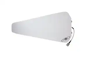
ANT-DB1-LP-RM-01-N
RF Antenna, 2.4 to 2.48GHz, Yagi, 9dBi, 50 ohm, Vertical, N Connector
⚠️ Reference pricing provided. In case of supply shortages, we will connect you with our trusted procurement partners to ensure your project's continuity.
- Manufacturer: TE CONNECTIVITY - LINX
- Product type:
- Gain: 9dBi
- SVHC: No SVHC (25-Jun-2025)
- VSWR: 1.5
- Input Power: 100W
- Antenna Type: Yagi
- Frequency Max: 2.48GHz
- Frequency Min: 2.4GHz
- Product Range: DB1-LP Series
- Input Impedance: 50ohm
- Antenna Mounting: N Connector
- Antenna Polarisation: Vertical
| Delivery and price | |
|---|---|
| Units per pack | 100 |
| Price | 62.67 € |
| Current stock | 10+ |
| Lead time | 30 days |
Datasheet

## **ANT-DB1-LP-RM-01-N Data Sheet**

## Product Description

The Antenna Factor Log Periodic antenna is designed for long-distance directional communication over a wide range of frequencies. The DB1-LP antenna provides gain and directivity comparable to a Yagi, but in a much smaller overall form factor, and over a considerably wider range of frequencies. Constructed of UV stabilized materials, the antenna is suitable for long-term use in indoor or outdoor environments. The antenna includes complete mounting hardware for standard masts. Note: Use of these antennas may result in TX and RX emission levels in excess of legal limits.

## Features

- High gain

- Wide bandwidth

- Fully weatherized

- N female connector

- Rugged & damage-resistant

- Excellent performance over common frequency antennas

**==> picture [133 x 95] intentionally omitted <==**

**----- Start of picture text -----**<br>
395.0 mm<br>(15.55")<br>N Style Connector<br>165.1 mm<br>(6.50")<br>**----- End of picture text -----**<br>


**==> picture [202 x 111] intentionally omitted <==**

**----- Start of picture text -----**<br>
7 m 2X M8x1.25<br>210.0 mm 80.0 mm<br>(8.27") (3.15")<br>or “ho<br>_ eno e| .yj, —_©<br>Mounting Hardware<br>36.5 mm<br>(included)<br>(1.44")<br>**----- End of picture text -----**<br>


## Electrical Specifications

Recom. Freq. Range: 824–960MHz 1.71–2.17GHz 2.40–2.48GHz Polarization: Vertical VSWR: ≤ 1.5 typ. at center Impedance: 50-ohms Gain: 8.5dBi (Band 1) 9.0dBi (Bands 2 and 3) 3dB H Beamwidth: 57º, 53º, 50º (Bands 1, 2, 3 resp.) 3dB V Beamwidth: 85º, 70º–80º, 70º (Bands 1, 2, 3 resp.) Max. Power: 100W Connector: N-style female Mounting: Bracket with U-bolts, 1.58"–1.97" (40–50mm) mast Weight : 2.4lbs (1.1kg) Wind Velocity: 75mph (120kph) Front/Back Ratio: ≥ 20dB

## Ordering Information

ANT-DB1-LP-RM-01-N (with N female connector)

Revised 2/20/2018

– **1** –

## VSWR Graph

**==> picture [366 x 169] intentionally omitted <==**

**----- Start of picture text -----**<br>
VSWR 1.161 1.226 1.113 Reflected Power<br>3:1 25%<br>2:1 11%<br>1:1 0%<br>Center 916MHz<br>Center 1910MHz Span 200MHz<br>Center 2450MHz<br>**----- End of picture text -----**<br>


## What is VSWR?

The Voltage Standing Wave Ratio (VSWR) is a measurement of how well an antenna is matched to a source impedance, typically 50-ohms. It is calculated by measuring the voltage wave that is headed toward the load versus the voltage wave that is reflected back from the load. A perfect match has a VSWR of 1:1. The higher the first number, the worse the match, and the more inefficient the system. Since a perfect match cannot ever be obtained, some benchmark for performance needs to be set. In the case of antenna VSWR, this is usually 2:1. At this point, 88.9% of the energy sent to the antenna by the transmitter is radiated into free space and 11.1% is either reflected back into the source or lost as heat on the structure of the antenna. In the other direction, 88.9% of the energy recovered by the antenna is transferred into the receiver. As a side note, since the “:1” is always implied, many data sheets will remove it and just display the first number.

## How to Read a VSWR Graph

VSWR is usually displayed graphically versus frequency. The lowest point on the graph is the antenna’s operational center frequency. In most cases, this is different than the designed center frequency due to fabrication tolerances. The VSWR at that point denotes how close to 50-ohms the antenna gets. Linx specifies the recommended bandwidth as the range where the typical antenna VSWR is less than 2:1.

Copyright © 2018 Linx Technologies

159 Ort Lane, Merlin, OR 97532 Phone: +1 541 471 6256 Fax: +1 541 471 6251 www.linxtechnologies.com

ANT-DB1-LP-RM-01-N Data Sheet

**– 2** –
Updated at June 9, 2026
About Novapart
Novapart is a B2B electronic component broker specialising in stock shortages and cost reduction. We source hard-to-find parts and identify compliant alternatives across a catalogue of 410,000+ components from 500+ manufacturers.
Learn more →Stock Shortage Specialist
When a component is unavailable, discontinued or has an unacceptable lead time, we tap into our network of vetted European and Asian distributors to source what you need — without compromising on quality or traceability.
Request a quote →Compliant Alternatives
We identify pin-to-pin, electrically equivalent substitutes that meet the same certifications (RoHS, AEC-Q100, REACH) as your original specification — validated against datasheets, not just part numbers. Often at a lower cost.
BOM Analysis service →