
Image not available
Illustrative purposes only

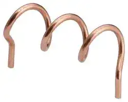
ANT-916-HETH
Helical Antenna, LoRaWAN/WiFi/LPWAN, 902MHz to 930MHz, 6.4dBi, 50ohm, 15W, 1.5VSWR, Linear, TH
⚠️ Reference pricing provided. In case of supply shortages, we will connect you with our trusted procurement partners to ensure your project's continuity.
- Manufacturer: TE CONNECTIVITY - LINX
- Product type:
- Gain: 6.4dBi
- SVHC: No SVHC (07-Nov-2024)
- VSWR: 1.5
- Input Power: 15W
- Antenna Type: Helical, LoRaWAN / WiFi / LPWAN
- Frequency Max: 930MHz
- Frequency Min: 902MHz
- Product Range: HE Series
- Input Impedance: 50ohm
- Antenna Mounting: Through Hole
- Antenna Polarisation: Linear
| Delivery and price | |
|---|---|
| Units per pack | 500 |
| Price | 0.589 € |
| Current stock | 1000+ |
| Lead time | 30 days |
Datasheet

## **HE Series**

## **916 MHz Helical Antenna**

Linx 916 MHz HE series compact printed circuit board (PCB) mount helical monopole antennas support low-power, wide-area (LPWA) applications including LoRaWAN®, remote controls, and ISM band applications in the 902 MHz to 930 MHz range.

The HE series antennas are made from 1.3 mm diameter berylium copper for use in PCB-mount installations requiring a rugged antenna design.

Designed for reflow-solder mounting directly to a printed circuit board for high-volume applications, the 916-HESM offers a surface-mount design and the 916-HETH is for use in a through-hole installation.

## **FEATURES**

- Performance at 916 MHz

   - VSWR: ≤ 1.5

   - Peak Gain: 6.4 dBi

   - Efficiency: 75%

- Direct PCB attachment

- Reflow- or hand-solder assembly

- Omnidirectional radiation pattern

- Compact size

## **APPLICATIONS**

   - Low-power, wide-area (LPWA) applications – LoRaWAN®

   - Remote control, monitoring and sensing

      - Security systems

      - Industrial machinery

      - Automated equipment

      - AMR (automated meter reading)

   - Internet of Things (IoT) devices

   - Smart Home networking

- 25.4 mm x 15.3 mm x 8.9 mm

- Hand-held devices

## **ORDERING INFORMATION**

|Part Number|Description|
|---|---|
|ANT-916-HESM|916 MHz helical surface-mount antenna|
|ANT-916-HETH|916 MHz helical through-hole antenna|


Available from Linx Technologies and select distributors and representatives.

DATA AND DEVICES / HE SERIES

## **TABLE 1. ELECTRICAL SPECIFICATIONS**

|ANT-8/9-IPW1-SMA|868 MHz|
|---|---|
|FrequencyRange|902 MHz to 930 MHz|
|VSWR(max)|1.5|
|Peak Gain(dBi)|6.4|
|Average Gain(dBi)|-1.4|
|Efficiency (%)|75|
|Polarization|Linear|
|Radiation|Omnidirectional|
|Max Power|15 W|
|Wavelength|1/4-wave|
|Electrical Type|Monopole|
|Impedance|50Ω|
|ESD Sensitivity|NOT ESD sensitive. As a bestpractice,Linx mayuse ESDpackaging.|


Electrical specifications and plots measured with a 84.0 mm x 38.0 mm (3.31 in x 1.50 in) reference ground plane.

## **TABLE 2. MECHANICAL SPECIFICATIONS**

|Parameter<br>~~ae~~|Value<br>~~ae~~|
|---|---|
|Connection<br>~~ae~~<br>|<br>||ANT-916-HESM = surface-mount, ANT-916-HETH = through-hole<br>~~ae~~<br>||
|Operating Temperature Range|-40 °C to +85 °C|
|Weight|1.0 g (0.04 oz)|
|Dimensions|25.4 mm x 15.3 mm x 8.9 (1.00 in x 0.60 in x 0.35 in)|


## **PRODUCT DIMENSIONS**

Figure 1 provides dimensions of the 916-HESM antenna. The dimensions of the 916-HETH antenna are shown in Figure 2.

Figure 1. 916-HESM Antenna Dimensions

DATA AND DEVICES / HE SERIES

2

Figure 2. 916-HETH Antenna Dimensions

## **PACKAGING INFORMATION**

The HE series antennas are packed in a clear plastic PVC bag, labeled with model number and quantity. Distribution channels may offer alternative packaging options.

## **VSWR**

Figure 3 provides the voltage standing wave ratio (VSWR) across the antenna bandwidth. VSWR describes the power reflected from the antenna back to the radio. A lower VSWR value indicates better antenna performance at a given frequency. Reflected power is also shown on the right-side vertical axis as a gauge of the percentage of transmitter power reflected back from the antenna.

**==> picture [458 x 223] intentionally omitted <==**

**----- Start of picture text -----**<br>
5<br>PLETEPUEEEEEE EEE 40<br>4<br>EEE<br>30<br>FLEREEEE EEE<br>FLEE<br>3<br>20<br>PLE<br>PUEEE<br>2<br>eeeEEE 10<br>TPETTITTE<br>1 TTT eee RRS eReEE eee 0<br>900 905 910 915 920 925 930 935<br>Frequency (MHz)<br>902 930<br>VSWR<br>Reflected Power (%)<br>**----- End of picture text -----**<br>


Figure 3. ANT-916-HE Series VSWR

DATA AND DEVICES / HE SERIES

3

## **RETURN LOSS**

Return loss (Figure 4), represents the loss in power at the antenna due to reflected signals. Like VSWR, a lower return loss value indicates better antenna performance at a given frequency.

**==> picture [460 x 225] intentionally omitted <==**

**----- Start of picture text -----**<br>
0<br>-2<br>-4<br>-6<br>-8<br>-10<br>-12<br>-14<br>-16<br>-18<br>-20<br>900 905 910 915 920 925 930 935<br>Frequency (MHz)<br>902 930<br>Return Loss (dB)<br>**----- End of picture text -----**<br>


Figure 4. 868-HE Series Return Loss

## **PEAK GAIN**

The peak gain across the antenna bandwidth is shown in Figure 5. Peak gain represents the maximum antenna input power concentration across 3-dimensional space, and therefore peak performance at a given frequency, but does not consider any directionality in the gain pattern.

**==> picture [460 x 226] intentionally omitted <==**

**----- Start of picture text -----**<br>
10<br>5<br>0<br>-5<br>-10<br>-15<br>-20<br>900 905 910 915 920 925 930 935<br>Frequency (MHz)<br>902 930<br>Peak Gain (dBi)<br>**----- End of picture text -----**<br>


Figure 5. ANT-916-HE Series Peak Gain

DATA AND DEVICES / HE SERIES

4

## **AVERAGE GAIN**

Average gain (Figure 6), is the average of all antenna gain in 3-dimensional space at each frequency, providing an indication of overall performance without expressing antenna directionality.

**==> picture [460 x 242] intentionally omitted <==**

**----- Start of picture text -----**<br>
10<br>5<br>0<br>-5<br>-10<br>-15<br>-20<br>900 905 910 915 920 925 930 935<br>Frequency (MHz)<br>Figure 6. ANT-916-HE Series Antenna Average Gain<br>902 930<br>Average Gain (dBi)<br>**----- End of picture text -----**<br>


## **RADIATION EFFICIENCY**

Radiation efficiency (Figure 7), shows the ratio of power delivered to the antenna relative to the power radiated at the antenna, expressed as a percentage, where a higher percentage indicates better performance at a given frequency.

**==> picture [461 x 241] intentionally omitted <==**

**----- Start of picture text -----**<br>
100<br>90<br>80<br>70<br>60<br>50<br>40<br>30<br>20<br>10<br>0<br>900 905 910 915 920 925 930 935<br>Frequency (MHz)<br>Figure 7. ANT-916-HE Series Antenna Radiation Efficiency<br>902 930<br>Efficiency (%)<br>**----- End of picture text -----**<br>


DATA AND DEVICES / HE SERIES

5

## **RADIATION PATTERNS**

Radiation patterns provide information about the directionality and 3-dimensional gain performance of the antenna by plotting gain at specific frequencies in three orthogonal planes. Antenna radiation patterns for an edge straight orientation are shown in Figure 8 using polar plots covering 360 degrees. The antenna graphic at the top of the page provides reference to the plane of the column of plots below it. Note: when viewed with typical PDF viewing software, zooming into radiation patterns is possible to reveal fine detail.

**==> picture [43 x 5] intentionally omitted <==**

**----- Start of picture text -----**<br>
XZ-Plane Gain<br>**----- End of picture text -----**<br>


**==> picture [44 x 5] intentionally omitted <==**

**----- Start of picture text -----**<br>
YZ-Plane Gain<br>**----- End of picture text -----**<br>


XY-Plane Gain

## **902 MHZ TO 930 MHZ (915 MHZ)**

**==> picture [458 x 154] intentionally omitted <==**

**----- Start of picture text -----**<br>
35 36 5 1 2 3 35 36 5 1 2 3 35 36 5 1 2 3<br>34 0 4 34 0 4 34 0 4<br>33 -5 5 33 -5 5 33 -5 5<br>32 -10-15 6 32 -10-15 6 32 -10-15 6<br>31 -20 7 31 -20 7 31 -20 7<br>-25 -25 -25<br>30 -30 8 30 -30 8 30 -30 8<br>-35 -35 -35<br>29 -40 9 29 -40 9 29 -40 9<br>-45 -45 -45<br>28 -50 10 28 -50 10 28 -50 10<br>27 11 27 11 27 11<br>26 12 26 12 26 12<br>| 25 | { \ \ i" \ Silt: } 1 J / } 13 ] \ 25  \ \ A \ SEEM, / '] y// 13 / 25 \ \ \ \ SEE. /V // 13<br>24 14 24 14 24 14<br>23 15 23 15 23 15<br>SRE 22 21 20 19 18 17 x 16 22 21 es 20 19 18 17 16 22 Se 21 20 19 18 a 17 16 - 902.0915.0930.0<br>XZ-Plane Gain YZ-Plane Gain XY-Plane Gain<br>**----- End of picture text -----**<br>


Figure 8. ANT-916-HE Series Radiation Patterns

## **GROUND PLANE**

1/4-Wave monopole antennas require an associated ground plane counterpoise for proper operation. The size and location of the ground plane relative to the antenna will affect the overall performance of the antenna in the final design. When used in conjunction with a ground plane smaller than that used to tune the antenna, the center frequency typically will shift higher in frequency and the bandwidth will decrease. The proximity of other circuit elements and packaging near the antenna will also affect the final performance.

For further discussion and guidance on the importance of the ground plane counterpoise, please refer to Linx Application Note, AN-00501: Understanding Antenna Specifications and Operation.

DATA AND DEVICES / HE SERIES

6

## **RECOMMENDED LAYOUT**

The recommended printed circuit board (PCB) layout for the 916-HE Series antenna series is shown in Figure 9. Contact Linx for availability of PCB layout design files.

The recommended layout includes a matching network, ground plane and PCB transmission line from the antenna to the matching network, and to the connector or radio circuitry.

Linx recommends inclusion of at least a 3-element, surface mount pi matching network of two parallel capacitors, (X1, X3) and one serial inductor, (X2) in all designs (Figure 9). Surface mount components should be 0603 size. 0402 size components are also supported. The 916-HE series antenna, as designed, does not require matching, but matching may improve end-product antenna performance depending on the effects of the enclosure, PCB and other electronic components. If no matching is necessary, the serial

element may be populated with a zero-ohm resistor and no components in the two capacitor positions. This is the configuration of the Linx evaluation board as supplied. Linx believes in wireless made simple® and offers matching network design support.

Figure 9. 916-HE Series Antenna Recommended Layout.

Figure 10. Matching Network Recommendation

DATA AND DEVICES / HE SERIES

7

## **RECOMMENDED PCB FOOTPRINT**

Figure 11 shows the recommended printed circuit board footprint and spacing for the 868-HE series antenna. The footprint recommendation should be used in conjunction with the recommended layout configuration shown in Figure 9.

Figure 11. 868-HE Series Antenna Placement on PCB.

## **TRANSMISSION LINES FOR EMBEDDED ANTENNAS**

For most designs, Linx recommends a microstrip transmission line for the 916-HE Series antenna. A microstrip transmission line is a PCB trace that runs over a ground plane to maintain the characteristic impedance for optimal signal transfer between the antenna and radio circuitry. Linx designs all antennas with a characteristic impedance of 50 Ω.

Important practices to observe when designing a transmission line are:

- Keep all transmission lines to a minimum length for best signal performance

- Use RF components that also operate at a 50 Ω impedance

- If the radio is not on the same PCB as the antenna, the microstrip should be terminated in a connector, enabling a shielded cable to complete the antenna connection to the radio

- For designs subject to significant electromagnetic interference, a coplanar waveguide transmission line may be used on the PCB

The design of a PCB transmission line can be aided by many commercially available software packages which can calculate the correct transmission line width and gap dimensions based upon the PCB thickness and dielectric constant used. Linx offers PCB design reviews to help optimize solution performance.

## **REFLOW SOLDER PROFILE**

The HE series antennas use a typical RoHS solder reflow profile. Refer to application note AN-00504 on the Linx website for more information

DATA AND DEVICES / HE SERIES

8

## **ANTENNA DEFINITIONS AND USEFUL FORMULAS**

VSWR - Voltage Standing Wave Ratio. VSWR is a unitless ratio that describes the power reflected from the antenna back to the radio. A lower VSWR value indicates better antenna performance at a given frequency. VSWR is easily derived from Return Loss.

Return Loss - Return loss represents the loss in power at the antenna due to reflected signals, measured in decibels. A lower return loss value indicates better antenna performance at a given frequency. Return Loss is easily derived from VSWR.

Efficiency (η) - The total power radiated from an antenna divided by the input power at the feed point of the antenna as a percentage. Total Radiated Efficiency - (TRE) The total efficiency of an antenna solution comprising the radiation efficiency of the antenna and the transmitted (forward) efficiency from the transmitter.

Gain - The ratio of an antenna’s efficiency in a given direction (G) to the power produced by a theoretical lossless (100% efficient) isotropic antenna. The gain of an antenna is almost always expressed in decibels.

Peak Gain - The highest antenna gain across all directions for a given frequency range. A directional antenna will have a very high peak gain compared to average gain.

Average Gain - The average gain across all directions for a given frequency range.

Maximum Power - The maximum signal power which may be applied to an antenna feed point, typically measured in watts (W).

Reflected Power - A portion of the forward power reflected back toward the amplifier due to a mismatch at the antenna port.

decibel (dB) - A logarithmic unit of measure of the power of an electrical signal. decibel isotropic (dBi) - A comparative measure in decibels between an antenna under test and an isotropic radiator. decibel relative to a dipole (dBd) - A comparative measure in decibels between an antenna under test and an ideal half-wave dipole. Dipole - An ideal dipole comprises a straight electrical conductor measuring 1/2 wavelength from end to end connected at the center to a feed point for the radio.

Isotropic Radiator - A theoretical antenna which radiates energy equally in all directions as a perfect sphere. Omnidirectional - Term describing an antenna radiation pattern that is uniform in all directions. An isotropic antenna is the theoretical perfect omnidirectional antenna. An ideal dipole antenna has a donut- shaped radiation pattern and other practical antenna implementations will have less perfect but generally omnidirectional radiation patterns which are typically plotted on three axes.

DATA AND DEVICES / HE SERIES

9

## **TE  TECHNICAL SUPPORT CENTER**

USA: +1 (800) 522-6752 Canada: +1 (905) 475-6222 Mexico: +52 (0) 55-1106-0800 Latin/S. America: +54 (0) 11-4733-2200 Germany: +49 (0) 6251-133-1999 UK: +44 (0) 800-267666 France: +33 (0) 1-3420-8686 Netherlands: +31 (0) 73-6246-999 China: +86 (0) 400-820-6015

## **te.com**

TE Connectivity, TE, TE connectivity (logo), Linx and Linx Technologies are trademarks owned or licensed by the TE Connectivity Ltd. family of companies. All other logos, products and/or company names referred to herein might be trademarks of their respective owners.

The information given herein, including drawings, illustrations and schematics which are intended for illustration purposes only, is believed to be reliable. However, TE Connectivity makes no warranties as to its accuracy or completeness and disclaims any liability in connection with its use. TE Connectivity‘s obligations shall only be as set forth in TE Connectivity‘s Standard Terms and Conditions of Sale for this product and in no case will TE Connectivity be liable for any incidental, indirect or consequential damages arising out of the sale, resale, use or misuse of the product. Users of TE Connectivity products should make their own evaluation to determine the suitability of each such product for the specific application.

TE Connectivity warrants to the original end user customer of its products that its products are free from defects in material and workmanship. Subject to conditions and limitations TE Connectivity will, at its option, either repair or replace any part of its products that prove defective because of improper workmanship or materials. This limited warranty is in force for the useful lifetime of the original end product into which the TE Connectivity product is installed. Useful lifetime of the original end product may vary but is not warrantied to exceed one (1) year from the original date of the end product purchase.

©2022 TE Connectivity. All Rights Reserved.

**09/22   Original**

DATA AND DEVICES / HE SERIES
Updated at June 9, 2026
About Novapart
Novapart is a B2B electronic component broker specialising in stock shortages and cost reduction. We source hard-to-find parts and identify compliant alternatives across a catalogue of 410,000+ components from 500+ manufacturers.
Learn more →Stock Shortage Specialist
When a component is unavailable, discontinued or has an unacceptable lead time, we tap into our network of vetted European and Asian distributors to source what you need — without compromising on quality or traceability.
Request a quote →Compliant Alternatives
We identify pin-to-pin, electrically equivalent substitutes that meet the same certifications (RoHS, AEC-Q100, REACH) as your original specification — validated against datasheets, not just part numbers. Often at a lower cost.
BOM Analysis service →