
Image not available
Illustrative purposes only

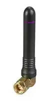
ANT-916-CW-RCS
RF Antenna, 902 to 930MHz, 4.8dBi, LoRaWAN/Sigfox/Weightless-P/WiFi, 50ohm, Linear, RP SMA Connector
⚠️ Reference pricing provided. In case of supply shortages, we will connect you with our trusted procurement partners to ensure your project's continuity.
- Manufacturer: TE CONNECTIVITY - LINX
- Product type:
- Gain: 4.8dBi
- SVHC: Lead (21-Jan-2025)
- VSWR: 2
- Input Power: 5W
- Antenna Type: LoRaWAN / Sigfox / Weightless-P / WiFi
- Frequency Max: 930MHz
- Frequency Min: 902MHz
- Product Range: RCS Series
- Input Impedance: 50ohm
- Antenna Mounting: RP SMA Connector
- Antenna Polarisation: Linear
| Delivery and price | |
|---|---|
| Units per pack | 500 |
| Price | 6.16 € |
| Current stock | 10+ |
| Lead time | 30 days |
Datasheet

## Datasheet

## CW-RCS Series 915 MHz Right-Angle Whip Antenna

The ANT-916-CW-RCS antenna is designed for sub-1 GHz and low-power, wide-area (LPWA) applications including LoRaWAN[®] and ISM band applications in the 902 MHz to 930 MHz band.

The right-angle rotating design of the ANT-916CW-RCS antenna allows for the antenna to be positioned for optimum performance.

The ANT-916-CW-RCS is available with an SMA plug (male pin) or RP-SMA plug (female socket) connector.

ANT-916-CW-RCS-SMA shown

## Features

- Performance at 902 MHz to 930 MHz

   - VSWR: ≤ 2.0

   - Peak Gain: 4.8 dBi

   - Efficiency: 69%

- Compact size

   - 54.0 mm x Ø9.4 mm

- Rotating base allows for optimal positioning

- SMA plug (male pin) or RP-SMA plug (female socket)

## Applications

- Low-power, wide-area (LPWA) applications

   - LoRaWAN[®] , ITU-T Y.4480

- ISM applications

- Remote control, sensing and monitoring

   - Security systems

   - Industrial machinery

   - Automated equipment

   - AMR (automated meter reading)

- Internet of Things (IoT) devices

- Smart Home networking

## Ordering Information

|Part Number|Description|
|---|---|
|ANT-916-CW-RCS-SMA|915 MHz right-angle whip antenna with SMA plug (male pin)|
|ANT-916-CW-RCS|915 MHz right-angle whip antenna with RP-SMA plug (female socket)|


Available from Linx Technologies and select distributors and representatives.

ANT-916-CW-RCS-ccc

Datasheet

Table 1.  Electrical Specifications

**==> picture [470 x 133] intentionally omitted <==**

**----- Start of picture text -----**<br>
Parameter Value<br>Frequency Range 902 MHz to 930 MHz<br>VSWR (max) 2.0<br>Peak Gain (dBi) 4.8<br>Average Gain (dBi) -1.7<br>Efficiency (%) 69<br>Polarization Linear Radiation Omnidirectional<br>Impedance 50  Ω Max Power 5 W<br>Wavelength 1/4-wave Electrical Type Monopole<br>**----- End of picture text -----**<br>


Electrical specifications and plots measured with a 102 mm x 102 mm (4.0 in x 4.0 in) reference ground plane.

Table 2.  Mechanical Specifications

**==> picture [469 x 73] intentionally omitted <==**

**----- Start of picture text -----**<br>
Parameter Value<br>Connection SMA plug (male pin), RP-SMA plug (female socket)<br>Dimensions 54.0 mm x Ø9.4 mm (2.13 in x Ø0.37 in)<br>Weight 8.4 g (0.30 oz)<br>Operating Temp. Range -20 °C to +85 °C<br>**----- End of picture text -----**<br>


## Product Dimensions

Figure 1 provides dimensions for the ANT-916-CW-RCS-ccc series antenna.

**==> picture [270 x 223] intentionally omitted <==**

**----- Start of picture text -----**<br>
54.0 mm<br>(2.13 in) 46.0 mm<br>(1.81 in)<br>Ø7.0 mm<br>(0.28 in)<br>Ø9.4 mm<br>(0.37 in)<br>17.4 mm<br>(0.69 in)<br>**----- End of picture text -----**<br>


Figure 1. ANT-916-CW-RCS-ccc Antenna Dimensions

## Packaging Information

The ANT-916-CW-RCS series antenna is individually packaged in a sealed plastic bag in quantities of 100 pcs. Bags are packaged in cartons. Distribution channels may offer alternative packaging options.

**==> picture [63 x 36] intentionally omitted <==**

**2**

ANT-916-CW-RCS-ccc

Datasheet

## Counterpoise

Quarter-wave or monopole antennas require an associated ground plane counterpoise for proper operation. The size and location of the ground plane relative to the antenna will affect the overall performance of the antenna in the final design. When used in conjunction with a ground plane smaller than that used to tune the antenna, the center frequency typically will shift higher in frequency and the bandwidth will decrease. The proximity of other circuit elements and packaging near the antenna will also affect the final performance.

For further discussion and guidance on the importance of the ground plane counterpoise, please refer to Linx Application Note, _AN-00501: Understanding Antenna Specifications and Operation_ .

## Antenna Orientation

The ANT-916-CW-RCS-ccc antenna is characterized at the edge of a ground plane as shown in Figure 2. Characterization at the edge of the ground plane (102 mm x 102 mm) provides insight into antenna performance when attached to a connector on a metal enclosure. The two orientations represent the most common end-product use case.

Figure 2. ANT-916-CW-RCS-ccc Test Orientation

**3**

ANT-916-CW-RCS-ccc

Datasheet

## VSWR

Figure 3 provides the voltage standing wave ratio (VSWR) across the antenna bandwidth. VSWR describes the power reflected from the antenna back to the radio. A lower VSWR value indicates better antenna performance at a given frequency. Reflected power is also shown on the right-side vertical axis as a gauge of the percentage of transmitter power reflected back from the antenna.

**==> picture [457 x 223] intentionally omitted <==**

**----- Start of picture text -----**<br>
5<br>40<br>4<br>30<br>3<br>20<br>2<br>10<br>1 0<br>900 902 904 906 908 910 912 914 916 918 920 922 924 926 928 930 932<br>Frequency (MHz)<br>902 930<br>VSWR<br>Reflected Power (%)<br>**----- End of picture text -----**<br>


Figure 3. ANT-916-CW-RCS-ccc Antenna VSWR

## Return Loss

Return loss (Figure 4), represents the loss in power at the antenna due to reflected signals. Like VSWR, a lower return loss value indicates better antenna performance at a given frequency.

**==> picture [460 x 225] intentionally omitted <==**

**----- Start of picture text -----**<br>
0<br>-2<br>-4<br>-6<br>-8<br>-10<br>-12<br>-14<br>-16<br>-18<br>-20<br>900 902 904 906 908 910 912 914 916 918 920 922 924 926 928 930 932<br>Frequency (MHz)<br>902 930<br>Return Loss (dB)<br>**----- End of picture text -----**<br>


Figure 4. ANT-916-CW-RCS-ccc Return Loss

**==> picture [63 x 36] intentionally omitted <==**

**4**

ANT-916-CW-RCS-ccc

Datasheet

## Peak Gain

The peak gain across the antenna bandwidth is shown in Figure 5. Peak gain represents the maximum antenna input power concentration across 3-dimensional space, and therefore peak performance at a given frequency, but does not consider any directionality in the gain pattern.

**==> picture [459 x 226] intentionally omitted <==**

**----- Start of picture text -----**<br>
10<br>5<br>0<br>-5<br>-10<br>-15<br>-20<br>900 902 904 906 908 910 912 914 916 918 920 922 924 926 928 930 932<br>Frequency (MHz)<br>902 930<br>Peak Gain (dBi)<br>**----- End of picture text -----**<br>


Figure 5. ANT-916-CW-RCS-ccc Peak Gain

## Average Gain

Average gain (Figure 6), is the average of all antenna gain in 3-dimensional space at each frequency, providing an indication of overall performance without expressing antenna directionality.

**==> picture [459 x 225] intentionally omitted <==**

**----- Start of picture text -----**<br>
10<br>5<br>0<br>-5<br>-10<br>-15<br>-20<br>900 902 904 906 908 910 912 914 916 918 920 922 924 926 928 930 932<br>Frequency (MHz)<br>902 930<br>Average Gain (dBi)<br>**----- End of picture text -----**<br>


Figure 6. ANT-916-CW-RCS-ccc Antenna Average Gain

**==> picture [63 x 36] intentionally omitted <==**

**5**

ANT-916-CW-RCS-ccc

Datasheet

## Radiation Efficiency

Radiation efficiency (Figure 7), shows the ratio of power delivered to the antenna relative to the power radiated at the antenna, expressed as a percentage, where a higher percentage indicates better performance at a given frequency.

**==> picture [460 x 225] intentionally omitted <==**

**----- Start of picture text -----**<br>
100<br>90<br>80<br>70<br>60<br>50<br>40<br>30<br>20<br>10<br>0<br>900 902 904 906 908 910 912 914 916 918 920 922 924 926 928 930 932<br>Frequency (MHz)<br>902 930<br>Efficiency (%)<br>**----- End of picture text -----**<br>


Figure 7. ANT-916-CW-RCS-ccc Antenna Radiation Efficiency

**==> picture [63 x 36] intentionally omitted <==**

**6**

ANT-916-CW-RCS-ccc

Datasheet

## Radiation Patterns

Radiation patterns provide information about the directionality and 3-dimensional gain performance of the antenna by plotting gain at specific frequencies in three orthogonal planes. Antenna radiation patterns are shown in Figure 8 using polar plots covering 360 degrees. The antenna graphic at the top of the page provides reference to the plane of the column of plots below it. Note: when viewed with typical PDF viewing software, zooming into radiation patterns is possible to reveal fine detail.

**==> picture [361 x 7] intentionally omitted <==**

**----- Start of picture text -----**<br>
XZ-Plane Gain YZ-Plane Gain XY-Plane Gain<br>**----- End of picture text -----**<br>


## 902 MHz to 930 MHz (915 MHz)

**==> picture [461 x 153] intentionally omitted <==**

**----- Start of picture text -----**<br>
35 36 5 1 2 3 35 36 5 1 2 3 35 36 5 1 2 3<br>33 a 34 x \ 0 |_...| Pw 4 5 33 34 a | 0 WN 4 5 33 34 a 0 ao ~~ 4 5<br>32 Lo oN -5 ~ \\ 6 32 Lo4 A=pa -5 SN~~ \\ 6 32 /4a so -5 we _ ~\ 6<br>31 L fVa A \— -10 L LO A ~ \ 7 31 / poxBON oma? -10 Sewe SR\ \ 7 31 ;/ vA Jt -10 aS \ \ 7<br>30 |f_/ J xx OQAv\DTT -15 HLTTA ~TX,>i \ \\ 8 30 // LKaa 7 \ao, -15 ALE \XN\ \ \ 8 30 [|/ /flfy/ y a > -15 neON7 -~NWN \\ \ \ 8<br>29 / /-~ i a/ xx -20 xx \x \ \—~\ \\ 9 29 // | / yf i -20 x ™‘ .\ \ \\ 9 29 |[+/ / / x -20 v- NX\ \-\\\—\ \ \ \ \ 9<br>28 \\ {\\ \\ |t | -25 =ts x = ITI} ||t ||t ||} 10 28 {\\ {\\ |\ {\| {\ \ -25 {\ \ . }| ]}) }|} ||| || ||) 10 28 {\\ {\\ |\ {\\ {\\ -25 {\ eo / \} }}| }|} ||| 1\/ ||| 10<br>27 Lf TEAS TA +H] 11 27 | lf \ | i ey ae ee, | 11 27 LA YY NEF | 11<br>26 \VXA YX SC/TAK \) Sv yaIAa / 7 {| 12 26 \LK\ \KONe / \a OLSJ~/ / 12 26 \AX\ \ \RO NS a OL- Sf/ f / 12<br>25 \x 24 \x\~~ 4TT ay\ he8*/ / 14 / 13 25 \ 24 \ \YeS\ wePtoA 7vA Wy 14 // 13 25 \\ 24 \~\SLSLITT4 YJoo y, / 14 / 13<br>N 23 NX 22 NOL/PA > HAANa a XX_ 16 AWA 15 \ 23 NN 22 NNa ~ Veneta~eeeee aa 16 wa/ 15 \ 23 ~ 22 _ae™weeee—a 16 4/ 15 _ 902 MHz<br>21 20 19 18 17 21 20 19 18 17 21 20 19 18 17 915 MHz930 MHz<br>XZ-Plane Gain YZ-Plane Gain XY-Plane Gain<br>**----- End of picture text -----**<br>


Figure 8. ANT-916-CW-RCS-ccc Radiation Patterns

**7**

ANT-916-CW-RCS-ccc

Datasheet

Website: http://linxtechnologies.com Linx Offices: 159 Ort Lane, Merlin, OR, US 97532 Phone: +1 (541) 471-6256 E-MAIL: info@linxtechnologies.com

Linx Technologies reserves the right to make changes to the product(s) or information contained herein without notice. No liability is assumed as a result of their use or application. No rights under any patent accompany the sale of any such product(s) or information.

Wireless Made Simple is a registered trademark of Linx Acquisitions LLC. LoRaWAN is a registered trademark of Semtech Corporation. Other product and brand names may be trademarks or registered trademarks of their respective owners. Copyright © 2022 Linx Technologies All Rights Reserved

Doc# DS22170-247ANT
Updated at June 9, 2026
About Novapart
Novapart is a B2B electronic component broker specialising in stock shortages and cost reduction. We source hard-to-find parts and identify compliant alternatives across a catalogue of 410,000+ components from 500+ manufacturers.
Learn more →Stock Shortage Specialist
When a component is unavailable, discontinued or has an unacceptable lead time, we tap into our network of vetted European and Asian distributors to source what you need — without compromising on quality or traceability.
Request a quote →Compliant Alternatives
We identify pin-to-pin, electrically equivalent substitutes that meet the same certifications (RoHS, AEC-Q100, REACH) as your original specification — validated against datasheets, not just part numbers. Often at a lower cost.
BOM Analysis service →