
Image not available
Illustrative purposes only

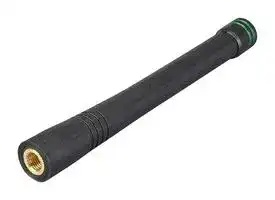
ANT-433-CW-HD
RF Antenna, 420 to 445MHz, 0.7dBi, LoRaWAN, Weightless-P, 50ohm, Linear, RP SMA Connector
⚠️ Reference pricing provided. In case of supply shortages, we will connect you with our trusted procurement partners to ensure your project's continuity.
- Manufacturer: TE CONNECTIVITY - LINX
- Product type:
- Gain: 0.7dBi
- SVHC: Lead (21-Jan-2025)
- VSWR: 2
- Input Power: -
- Antenna Type: LoRaWAN, Weightless-P
- Frequency Max: 445MHz
- Frequency Min: 420MHz
- Product Range: HD Series
- Input Impedance: 50ohm
- Antenna Mounting: RP SMA Connector
- Antenna Polarisation: Linear
| Delivery and price | |
|---|---|
| Units per pack | 500 |
| Price | 7.54 € |
| Current stock | 10+ |
| Lead time | 30 days |
Datasheet

## **ANT-433-CW-HD Data Sheet**

**==> picture [16 x 14] intentionally omitted <==**

**----- Start of picture text -----**<br>
by<br>**----- End of picture text -----**<br>


## Product Description

This reduced-height ¼-wave antenna is ready for years of use thanks to a flexible internal helical that is over-molded with a heavy-duty protective jacket. It’s an excellent choice for outdoor applications or for use in adverse environments where the antenna must resist shock, harsh weather and tampering. HD Series antennas attach via standard SMA or FCC Part 15 compliant RP-SMA connector.

## Features

- Reduced-height helical whip

- Excellent performance

- Omni-directional pattern

- Very low VSWR

- Heavy-duty construction

- Damage-resistant

- Fully weatherized

- Flexible main shaft

- Standard SMA or Part 15 compliant RP-SMA connector

- Use with plastic* or metal enclosures

- Requires proximity ground plane

## Electrical Specifications

Center Frequency: 433MHz Recom. Freq. Range: 420–445MHz Wavelength: ¼-wave VSWR: ≤ 2.0 typical at center Peak Gain: 0.7dBi Impedance: 50-ohms Connection: RP-SMA or SMA Oper. Temp. Range: –30°C to +70°C Electrical specifications and plots measured on a 10.16 cm x 10.16 cm (4.00" x 4.00") reference ground plane

**==> picture [183 x 355] intentionally omitted <==**

**----- Start of picture text -----**<br>
ke 12.3 mm(0.48")<br>13.5 mm<br>(0.53")<br>i<br>10.5 mm<br>(0.41")<br>88.0 mm<br>(3.46")<br>45.0 mm<br>(1.77”)<br>*<br>6.0 mm<br>| 0.24"<br>ft<br>(0.53")<br>13.5 mm<br>End View<br>ke 6.4 mm(0.25”)<br>**----- End of picture text -----**<br>


## Ordering Information

ANT-433-CW-HD ANT-433-CW-HD-SMA

– **1** –

Revised 5/16/14

## Counterpoise

Quarter-wave or monopole antennas require an associated ground plane counterpoise for proper operation. The size and location of the ground plane relative to the antenna will affect the overall performance of the antenna in the final design. When used in conjunction with a ground plane smaller than that used to tune the antenna, the center frequency typically will shift higher in frequency and the bandwidth will decrease. The proximity of other circuit elements and packaging near the antenna will also affect the final performance. For further discussion and guidance on the importance of the ground plane counterpoise, please refer to Linx Application Note AN-00501: Understanding Antenna Specifications and Operation.

## VSWR Graph

**==> picture [315 x 121] intentionally omitted <==**

**----- Start of picture text -----**<br>
VSWR 1.489 Reflected Power<br>3:1 25%<br>2:1 11%<br>1:1 0%<br>358MHz 433MHz 508MHz<br>**----- End of picture text -----**<br>


## What is VSWR?

The Voltage Standing Wave Ratio (VSWR) is a measurement of how well an antenna is matched to a source impedance, typically 50-ohms. It is calculated by measuring the voltage wave that is headed toward the load versus the voltage wave that is reflected back from the load. A perfect match will have a VSWR of 1:1. The higher the first number, the worse the match, and the more inefficient the system. Since a perfect match cannot ever be obtained, some benchmark for performance needs to be set. In the case of antenna VSWR, this is usually 2:1. At this point, 88.9% of the energy sent to the antenna by the transmitter is radiated into free space and 11.1% is either reflected back into the source or lost as heat on the structure of the antenna. In the other direction, 88.9% of the energy recovered by the antenna is transferred into the receiver. As a side note, since the “:1” is always implied, many data sheets will remove it and just display the first number.

## How to Read a VSWR Graph

VSWR is usually displayed graphically versus frequency. The lowest point on the graph is the antenna’s operational center frequency. In most cases, this will be different than the designed center frequency due to fabrication tolerances. The VSWR at that point denotes how close to 50-ohms the antenna gets. Linx specifies the recommended bandwidth as the range where the typical antenna VSWR is less than 2:1.

159 Ort Lane, Merlin, OR, US 97532 Phone: +1 541 471 6256 Fax: +1 541 471 6251 www.linxtechnologies.com

Data Sheet ANT-433-CW-HD

**– 2** –

by
Updated at June 9, 2026
About Novapart
Novapart is a B2B electronic component broker specialising in stock shortages and cost reduction. We source hard-to-find parts and identify compliant alternatives across a catalogue of 410,000+ components from 500+ manufacturers.
Learn more →Stock Shortage Specialist
When a component is unavailable, discontinued or has an unacceptable lead time, we tap into our network of vetted European and Asian distributors to source what you need — without compromising on quality or traceability.
Request a quote →Compliant Alternatives
We identify pin-to-pin, electrically equivalent substitutes that meet the same certifications (RoHS, AEC-Q100, REACH) as your original specification — validated against datasheets, not just part numbers. Often at a lower cost.
BOM Analysis service →