
Image not available
Illustrative purposes only

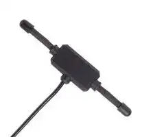
ANT-418-MHW-RPS-L
RF Antenna, 408 to 428MHz, 2.1dBi, LTE, 50ohm, Linear, RP SMA Connector
⚠️ Reference pricing provided. In case of supply shortages, we will connect you with our trusted procurement partners to ensure your project's continuity.
- Manufacturer: TE CONNECTIVITY - LINX
- Product type:
- Gain: 2.1dBi
- SVHC: Lead (21-Jan-2025)
- VSWR: 1.9
- Input Power: -
- Antenna Type: LTE
- Frequency Max: 428MHz
- Frequency Min: 408MHz
- Product Range: MHW Series
- Input Impedance: 50ohm
- Antenna Mounting: RP SMA Connector
- Antenna Polarisation: Linear
| Delivery and price | |
|---|---|
| Units per pack | 500 |
| Price | 13.89 € |
| Current stock | 10+ |
| Lead time | 30 days |
Datasheet

## **ANT-418-MHW-xxx-x Data Sheet** ## by ## Product Description MHW Series dipole antennas feature a durable, unobtrusive housing that sticks permanently with integral adhesive to fl at, non-conductive surfaces such as windows, drywall, ceiling tiles, plastic, etc. The antennas are well suited to low-power devices, but are capable of operation at levels to 10 watts. The MHW is supplied with either 79" [2m] or 180" [4.6m] of RG-174 cable and attaches via a standard SMA or Part 15 compliant RP-SMA connector. Custom cable lengths and connectors are available for volume OEM customers. ## Features - Compact & unobtrusive - Adhesive for fl at surfaces - Excellent performance - Omni-directional pattern - Very low VSWR - Two fl exible radiating elements **==> picture [176 x 250] intentionally omitted <==** **----- Start of picture text -----**<br> ( 5.91"[150] )<br>0.38"<br>[9.7]<br>* v<br>0.30"<br>[7.6]<br>2.28" 1.34"<br>( [58.0] ) [34.0]<br>/#——++ — |<br>,<br>0.22"<br>[5.5] = 0.61"<br>[15.5]<br>i<br>0.31"<br>[8.0]<br>**----- End of picture text -----**<br> - Rugged & damage-resistant - Standard SMA or Part 15 compliant RP-SMA connector ## Center frequency: 418MHz Recommended Oper. Freq: 408–428MHz Wavelength: ½-wave VSWR: 1.9 typical at center Peak Gain: 2.1dBi Impedance: 50-ohms Connection: SMA or RP-SMA Cable: 79" or 180" RG-174 coax ## Ordering Information ANT-418-MHW-RPS-L (RP-SMA connector, 180" [4.6m] coax) ANT-418-MHW-RPS-S (RP-SMA connector, 79" [2m] coax) ANT-418-MHW-SMA-L (SMA connector, 180" [4.6m] coax) ANT-418-MHW-SMA-S (SMA connector, 79" [2m] coax) – **1** – Revised 3/22/13 ## VSWR Graph **==> picture [313 x 121] intentionally omitted <==** **----- Start of picture text -----**<br> VSWR 1.687 Reflected Power<br>3:1 25%<br>2:1 11%<br>1:1 0%<br>353MHz 418MHz 473MHz<br>**----- End of picture text -----**<br> ## What is VSWR? The Voltage Standing Wave Ratio (VSWR) is a measurement of how well an antenna is matched to a source impedance, typically 50-ohms. It is calculated by measuring the voltage wave that is headed toward the load versus the voltage wave that is refl ected back from the load. A perfect match will have a VSWR of 1:1. The higher the fi rst number, the worse the match, and the more ineffi cient the system. Since a perfect match cannot ever be obtained, some benchmark for performance needs to be set. In the case of antenna VSWR, this is usually 2:1. At this point, 88.9% of the energy sent to the antenna by the transmitter is radiated into free space and 11.1% is either refl ected back into the source or lost as heat on the structure of the antenna. In the other direction, 88.9% of the energy recovered by the antenna is transferred into the receiver. As a side note, since the “:1” is always implied, many data sheets will remove it and just display the fi rst number. ## How to Read a VSWR Graph VSWR is usually displayed graphically versus frequency. The lowest point on the graph is the antenna’s operational center frequency. In most cases, this will be different than the designed center frequency due to fabrication tolerances. The VSWR at that point denotes how close to 50-ohms the antenna gets. Linx specifi es the recommended bandwidth as the range where the typical antenna VSWR is less than 2:1. Data Sheet ANT-418-MHW-xxx-x **– 2** – by ## Gain Plots **==> picture [213 x 7] intentionally omitted <==** **----- Start of picture text -----**<br> XZ-Plane Gain YZ-Plane Gain<br>**----- End of picture text -----**<br> **==> picture [88 x 191] intentionally omitted <==** **----- Start of picture text -----**<br> E / Vertical Gain<br>H / Horizontal Gain<br>Total Gain<br>ttPiss<br>a ) My .<br>veZe = D x BF<br>/ \ 4<br>= PTA |<br>\ / fii |<br>Spet geoe£ 2fF<br>“LLL || Lae<br>XY-Plane Gain<br>**----- End of picture text -----**<br> ## About Gain Plots The true measure of the effectiveness of an antenna in any given application is determined by the gain and radiation pattern measurement. For antennas gain is typically measured relative to a perfect (isotropic) radiator having the same source power as the antenna under test, the units of gain in this case will be decibels isotropic (dBi). The radiation pattern is a graphical representation of signal strength measured at fi xed distance from the antenna. Gain when applied to antennas is a measure of how the antenna radiates and focuses the energy received into free space. Much like a fl ashlight focuses light from a bulb into a specifi c direction, antennas can focus RF energy into specifi c directions. Gain in this sense refers to an increase in energy in one direction over others. It should also be understood that gain is not “free”, gain above 0dBi in one direction means that there must be less gain in another direction. Pictorially this can be pictured as shown in the fi gures to the right. The orange pattern represents the radiation pattern for a perfect dipole antenna, which is shaped like a donut. The pattern for an omnidirectional antenna with gain is shown in blue. The gain antenna is able to work with a device located further from the center along the axis of the pattern, but not with devices closer to the center when they are off the axis – the donut has been squished. Gain is also related to the overall physical size of the antenna, as well as surrounding materials. As the geometry of the antenna is reduced below the effective wavelength (considered an electrically small antenna) the gain will decrease. As well, the relative distance between an electrically small antenna and its associated ground will impact antenna gain. 159 Ort Lane, Merlin, OR, US 97532 Phone: +1 541 471 6256 Fax: +1 541 471 6251 www.linxtechnologies.com – **3** – Data Sheet ANT-418-MHW-xxx-x by
Updated at June 9, 2026
About Novapart
Novapart is a B2B electronic component broker specialising in stock shortages and cost reduction. We source hard-to-find parts and identify compliant alternatives across a catalogue of 410,000+ components from 500+ manufacturers.
Learn more →Stock Shortage Specialist
When a component is unavailable, discontinued or has an unacceptable lead time, we tap into our network of vetted European and Asian distributors to source what you need — without compromising on quality or traceability.
Request a quote →Compliant Alternatives
We identify pin-to-pin, electrically equivalent substitutes that meet the same certifications (RoHS, AEC-Q100, REACH) as your original specification — validated against datasheets, not just part numbers. Often at a lower cost.
BOM Analysis service →