
Image not available
Illustrative purposes only

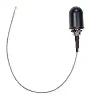
ANT-2.4-WRT-MON-RPS
RF Antenna, 2.4 to 2.5GHz, 2.7dBi, WiFi/WLAN/Bluetooth/ZigBee/ISM/IoT, Linear, RP SMA Connector
⚠️ Reference pricing provided. In case of supply shortages, we will connect you with our trusted procurement partners to ensure your project's continuity.
- Manufacturer: TE CONNECTIVITY - LINX
- Product type:
- Gain: 2.7dBi
- SVHC: No SVHC (25-Jun-2025)
- VSWR: 1.7
- Input Power: 5W
- Antenna Type: WiFi / WLAN / Bluetooth / ZigBee / ISM / IoT
- Frequency Max: 2.5GHz
- Frequency Min: 2.4GHz
- Product Range: WRT-MON Series
- Input Impedance: 50ohm
- Antenna Mounting: RP SMA Connector
- Antenna Polarisation: Linear
| Delivery and price | |
|---|---|
| Units per pack | 1000 |
| Price | 12.49 € |
| Current stock | 10+ |
| Lead time | 30 days |
Datasheet

## **ANT-2.4-WRT-MON-ccc**

**==> picture [117 x 7] intentionally omitted <==**

**----- Start of picture text -----**<br>
ANT-2.4-WRT-MON-SMA Shown<br>**----- End of picture text -----**<br>


## **2.4 GHz WiFi External Panel-Mount Antenna**

The ANT-2.4-WRT-MON is a low-profile, panel-mount monopole antenna designed for 2.4 GHz WiFi/WLAN and ISM applications including Bluetooth® and ZigBee®. The ANT-2.4-WRT-MON antenna’s compact size allows it to be mounted securely in enclosures requiring added security. The ANT-2.4-WRT-MON antenna’s compact profile and rugged dome reduces the likelihood of accidental damage versus a whip antenna. The antenna connects to the radio via SMA plug (male pin), RP-SMA plug (female socket) MHF1/ U.FL-type plug (female socket) or MHF4 plug (female socket) on 216 mm (8.5 in.) coaxial cable.

## **FEATURES**

- Performance at 2.4 GHz to 2.5 GHz

   - VSWR: ≤ 1.7

   - Peak Gain: 2.7 dBi

      - Efficiency: 82%

   -

- Low-profile

   - Height: 27.0 mm (1.06 in)

- Mounts permanently with pressure sensitive adhesive ring and provided hex nut

## **APPLICATIONS**

- Single-band WiFi/WLAN – 802.11b/g

- 2.4 GHz ISM applications – Bluetooth®

   - ZigBee®

   - IEEE 802.15.4

- Internet of Things (IoT) devices

- Smart Home networking

   - Sensing and remote monitoring

   - Security

## **ORDERING INFORMATION**

|Part Number|Description|
|---|---|
|ANT-2.4-WRT-MON-RPS|Antenna with 216 mm (8.5 in) of RG-174 coaxial cable with an RP-SMA plug<br>(female socket) connector|
|ANT-2.4-WRT-MON-SMA|Antenna with 216 mm (8.5 in) of RG-174 coaxial cable with an SMA plug (male pin)<br>connector|
|ANT-2.4-WRT-MON-UFL|Antenna with 216 mm (8.5 in) of 1.32 mm coaxial cable with an MHF1/U.FL-type plug<br>(female socket) connector|
|ANT-2.4-WRT-MON-MHF4|Antenna with 216 mm (8.5 in) of 1.13 mm coaxial cable with an MHF4-type plug (female<br>socket) connector|


Available from Linx Technologies and select distributors and representatives.

DATA AND DEVICES / ANT-2.4-WRT-MON-CCC

## **TABLE 1. ELECTRICAL SPECIFICATIONS**

**==> picture [527 x 127] intentionally omitted <==**

**----- Start of picture text -----**<br>
ANT-2.4-WRT-MON 2.4 GHz<br>Frequency Range 2.4 GHz to 2.5 GHz<br>VSWR (max.) 1.7<br>Peak Gain (dBi) 2.7<br>Average Gain (dBi) -1.0<br>Efficiency (%) 82<br>Polarization Linear Radiation Omnidirectional<br>Impedance 50 Ω Max Power 5 W<br>Wavelength 1/4-wave Electrical Type Monopole<br>**----- End of picture text -----**<br>


Electrical specifications and plots measured with a 102 mm x 102 mm (4.0 in x 4.0 in) reference ground plane.

## **TABLE 2. MECHANICAL SPECIFICATIONS**

**==> picture [528 x 130] intentionally omitted <==**

**----- Start of picture text -----**<br>
Parameter Value<br>Operating Temp. Range -40 °C to +85 °C<br>Weight -MHF4 = 13.8 g (0.49 oz), -RPS & -SMA = 18.9 g (0.66 oz), -UFL = 13.9 g (0.49 oz)<br>MHF4 plug (female socket) on 1.13 mm coaxial cable<br>RP-SMA plug (female socket) on RG-174 coaxial cable<br>Connection<br>SMA plug (male pin) on RG-174 coaxial cable<br>MHF1/U.FL-type plug (female socket) on 1.32 mm coaxial cable<br>Coaxial Cable, minimum inside<br>RG-174: 10.2 mm (0.40 in), 1.13 mm: 5.0 mm (0.20 in), 1.32 mm: 6.0 mm (0.24 in)<br>bend radius<br>Dimensions Height: 27.0 mm (1.06 in), Diameter: 19.0 mm (0.75 in)<br>**----- End of picture text -----**<br>


## **PRODUCT INFORMATION**

The ANT-2.4-WRT-MON series antenna is individually sealed in a clear plastic bag. Individual packages are packed in a bag of 100 pcs. Distribution channels may offer alternative packaging options.

## **PRODUCT DIMENSIONS**

Figure 1 provides dimensions for the ANT-2.4-WRT-MON series antenna.

**==> picture [404 x 131] intentionally omitted <==**

**----- Start of picture text -----**<br>
Adhesive Ring Ø19.0 mm<br>(0.75 in)<br>7/16-28 UNEF<br>Hex Nut<br>-SMA, -RPS<br>-UFL<br>8.0 mm<br>(0.31 in)<br>27.0 mm<br>-MHF4<br>(1.06 in)<br>216.0 mm (8.5 in)<br>**----- End of picture text -----**<br>


**==> picture [148 x 6] intentionally omitted <==**

**----- Start of picture text -----**<br>
Figure 1: ANT-2.4-WRT-MON Antenna Dimensions<br>**----- End of picture text -----**<br>


DATA AND DEVICES / ANT-2.4-WRT-MON-CCC

2

## **RECOMMENDED MOUNTING**

The recommended enclosure mounting dimensions are shown in Figure 2. The ANT-2.4-WRT-MON series antenna is supplied with an integrated closed-cell pressure sensitive adhesive ring which helps seal enclosures against external elements. The adhesive ring has a protective plastic backing that must be removed prior to installation. A pull tab has been provided for easy removal of the protective backing. The antenna can be permanently mounted using the provided hex nut which should be tightened to 3.0 kgf/cm (5 in/lbs) max. The recommended maximum enclosure wall thickness is 3.18 mm (0.125 in).

**==> picture [38 x 16] intentionally omitted <==**

**----- Start of picture text -----**<br>
Ø10.8 mm<br>(0.43 in)<br>**----- End of picture text -----**<br>


Figure 2. ANT-2.4-WRT-MON Series Antenna Recommended Enclosure Mounting Dimensions

## **GROUND PLANE**

1/4-Wave monopole antennas require an associated ground plane counterpoise for proper operation. The size and location of the ground plane relative to the antenna will affect the overall performance of the antenna in the final design. When used in conjunction with a ground plane smaller than that used to tune the antenna, the center frequency typically will shift higher in frequency and the bandwidth will decrease. The proximity of other circuit elements and packaging near the antenna will also affect the final performance. For further discussion and guidance on the importance of the ground plane counterpoise, please refer to Linx Application Note, _AN-00501: Understanding Antenna Specifications and Operation._

## **ANTENNA ORIENTATION**

The ANT-2.4-WRT-MON antenna is characterized with the antenna at the center of a 102 mm x 102 mm ground plane as shown in Figure 3

Figure 3. ANT-2.4-WRT-MON Test Orientation

DATA AND DEVICES / ANT-2.4-WRT-MON-CCC

3

## **VSWR**

Figure 4 provides the voltage standing wave ratio (VSWR) across the antenna bandwidth. VSWR describes the power reflected from the antenna back to the radio. A lower VSWR value indicates better antenna performance at a given frequency. Reflected power is also shown on the right-side vertical axis as a gauge of the percentage of transmitter power reflected back from the antenna.

**==> picture [464 x 548] intentionally omitted <==**

**----- Start of picture text -----**<br>
5<br>40<br>4<br>30<br>3<br>20<br>2<br>10<br>1 0<br>2400 2410 2420 2430 2440 2450 2460 2470 2480 2490 2500<br>Frequency (MHz)<br>Figure 4. ANT-2.4-WRT-MON VSWR<br>Return loss (Figure 5), represents the loss in power at the antenna due to reflected signals. Like VSWR, a lower return<br>loss value indicates better antenna performance at a given frequency<br>0<br>-5<br>-10<br>-15<br>-20<br>-25<br>2400 2410 2420 2430 2440 2450 2460 2470 2480 2490 2500<br>Frequency (MHz)<br>2400 2500<br>VSWR<br>Reflected Power (%)<br>2400 2500<br>Return Loss (dB)<br>**----- End of picture text -----**<br>


## **RETURN LOSS**

Return loss (Figure 5), represents the loss in power at the antenna due to reflected signals. Like VSWR, a lower return loss value indicates better antenna performance at a given frequency

Figure 5. ANT-2.4-WRT-MON Return Loss

DATA AND DEVICES / ANT-2.4-WRT-MON-CCC

4

## **PEAK GAIN**

The peak gain across the antenna bandwidth is shown in Figure 6. Peak gain represents the maximum antenna input power concentration across 3-dimensional space, and therefore peak performance at a given frequency, but does not consider any directionality in the gain pattern

**==> picture [463 x 245] intentionally omitted <==**

**----- Start of picture text -----**<br>
5<br>0<br>-5<br>-10<br>-15<br>-20<br>2400 2410 2420 2430 2440 2450 2460 2470 2480 2490 2500<br>Frequency (MHz)<br>Figure 6. ANT-2.4-WRT-MON Peak Gain<br>2400 2500<br>Peak Gain (dBi)<br>**----- End of picture text -----**<br>


## **AVERAGE GAIN**

Average gain (Figure 7), is the average of all antenna gain in 3-dimensional space at each frequency, providing an indication of overall performance without expressing antenna directionality

**==> picture [463 x 244] intentionally omitted <==**

**----- Start of picture text -----**<br>
5<br>0<br>-5<br>-10<br>-15<br>-20<br>2400 2410 2420 2430 2440 2450 2460 2470 2480 2490 2500<br>Frequency (MHz)<br>Figure 7. ANT-2.4-WRT-MON Antenna Average Gain<br>2400 2500<br>Average Gain (dBi)<br>**----- End of picture text -----**<br>


DATA AND DEVICES / ANT-2.4-WRT-MON-CCC

5

## **RADIATION EFFICIENCY**

Radiation efficiency (Figure 8), shows the ratio of power delivered to the antenna relative to the power radiated at the antenna, expressed as a percentage, where a higher percentage indicates better performance at a given frequency.

**==> picture [465 x 232] intentionally omitted <==**

**----- Start of picture text -----**<br>
100<br>90<br>80<br>70<br>60<br>50<br>40<br>30<br>20<br>10<br>0<br>2400 2410 2420 2430 2440 2450 2460 2470 2480 2490 2500<br>Frequency (MHz)<br>2400 2500<br>Efficiency (%)<br>**----- End of picture text -----**<br>


Figure 8. ANT-2.4-WRT-MON Antenna Radiation Efficiency

## **RADIATION PATTERNS**

Radiation patterns provide information about the directionality and 3-dimensional gain performance of the antenna by plotting gain at specific frequencies in three orthogonal planes. Antenna radiation patterns are shown in Figure 9 using polar plots covering 360 degrees. The antenna graphic at the top of the page provides reference to the plane of the column of plots below it. Note: when viewed with typical PDF viewing software, zooming into radiation patterns is possible to reveal fine detail.

**==> picture [357 x 5] intentionally omitted <==**

**----- Start of picture text -----**<br>
XZ-Plane Gain YZ-Plane Gain XY-Plane Gain<br>**----- End of picture text -----**<br>


DATA AND DEVICES / ANT-2.4-WRT-MON-CCC

6

## **2400 MHZ TO 2500 MHZ (2450 MHZ)**

**==> picture [468 x 163] intentionally omitted <==**

**----- Start of picture text -----**<br>
35 36 5 1 2 3 35 36 5 1 2 3 35 36 5 1 2 3<br>34 0 4 34 0 4 34 0 4<br>33 -5 5 33 -5 5 33 -5 5<br>32 -10-15 6 32 -10-15 6 32 -10-15 6<br>31 -20 7 31 -20 7 31 -20 7<br>-25 -25 -25<br>30 -30 8 30 -30 8 30 -30 8<br>-35 -35 -35<br>29 -40 9 29 -40 9 29 -40 9<br>-45 -45 -45<br>28 -50 10 28 -50 10 28 -50 10<br>27 11 27 11 27 11<br>26 12 26 12 26 12<br>25 13 25 13 25 13<br>24 14 24 14 24 14<br>23 15 23 15 23 15<br>22 16 22 16 22 16 2400 MHz<br>21 20 19 18 17 21 20 19 18 17 21 20 19 18 17 2450 MHz2500 MHz<br>XZ-Plane Gain YZ-Plane Gain XY-Plane Gain<br>**----- End of picture text -----**<br>


Figure 9. ANT-2.4-WRT-MON Radiation Patterns

## **TE  TECHNICAL SUPPORT CENTER**

USA: +1 (800) 522-6752 Canada: +1 (905) 475-6222 Mexico: +52 (0) 55-1106-0800 Latin/S. America: +54 (0) 11-4733-2200 Germany: +49 (0) 6251-133-1999 UK: +44 (0) 800-267666 France: +33 (0) 1-3420-8686 Netherlands: +31 (0) 73-6246-999 China: +86 (0) 400-820-6015

## **te.com**

TE Connectivity, TE, TE connectivity (logo), Linx and Linx Technologies are trademarks owned or licensed by the TE Connectivity Ltd. family of companies. All other logos, products and/or company names referred to herein might be trademarks of their respective owners.

The information given herein, including drawings, illustrations and schematics which are intended for illustration purposes only, is believed to be reliable. However, TE Connectivity makes no warranties as to its accuracy or completeness and disclaims any liability in connection with its use. TE Connectivity‘s obligations shall only be as set forth in TE Connectivity‘s Standard Terms and Conditions of Sale for this product and in no case will TE Connectivity be liable for any incidental, indirect or consequential damages arising out of the sale, resale, use or misuse of the product. Users of TE Connectivity products should make their own evaluation to determine the suitability of each such product for the specific application.

TE Connectivity warrants to the original end user customer of its products that its products are free from defects in material and workmanship. Subject to conditions and limitations TE Connectivity will, at its option, either repair or replace any part of its products that prove defective because of improper workmanship or materials. This limited warranty is in force for the useful lifetime of the original end product into which the TE Connectivity product is installed. Useful lifetime of the original end product may vary but is not warrantied to exceed one (1) year from the original date of the end product purchase.

©2022 TE Connectivity. All Rights Reserved.

**09/22   Original**

DATA AND DEVICES / ANT-2.4-WRT-MON-CCC
Updated at June 9, 2026
About Novapart
Novapart is a B2B electronic component broker specialising in stock shortages and cost reduction. We source hard-to-find parts and identify compliant alternatives across a catalogue of 410,000+ components from 500+ manufacturers.
Learn more →Stock Shortage Specialist
When a component is unavailable, discontinued or has an unacceptable lead time, we tap into our network of vetted European and Asian distributors to source what you need — without compromising on quality or traceability.
Request a quote →Compliant Alternatives
We identify pin-to-pin, electrically equivalent substitutes that meet the same certifications (RoHS, AEC-Q100, REACH) as your original specification — validated against datasheets, not just part numbers. Often at a lower cost.
BOM Analysis service →