
Image not available
Illustrative purposes only

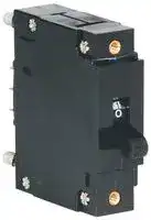
AM1R-D3-AC07D-A-20-2
CIRCUIT BREAKER, HYDROMAGNETIC, 1P, 250V
⚠️ Reference pricing provided. In case of supply shortages, we will connect you with our trusted procurement partners to ensure your project's continuity.
- Manufacturer: EATON HEINEMANN
- Product type: Magnetic Hydraulic Circuit Breakers
- CIRCUIT BREAKER, HYDROMAGNETIC, 1P, 250V, 20A; Product Range:AMR Series; Current Rating:20A; No. of Poles:1 Pole; Input Voltage VAC:250V; Interrupting Capacity:10kA; Trip Time:18
- Trip Time: 18s
- No. of Poles: 1 Pole
- Product Range: AMR Series
- Current Rating: 20A
- Input Voltage VAC: 250V
- Dielectric Strength: 2.5kV
- Interrupting Capacity: 10kA
| Delivery and price | |
|---|---|
| Units per pack | 250 |
| Price | 19.85 € |
| Current stock | 10+ |
| Lead time | 30 days |
Datasheet

**Heinemann[®] AM/R and AM1P Series Circuit Breakers**

## HEINEMANN® CIRCUIT BREAKERS

## AM/R and AM1P Series Circuit Breakers

## **DESCRIPTION**

Heinemann[®] Series AM/R circuit breakers are the logical choice for high quality service entrance and panelboard installations, as well as control and protection. The precisely tailored time delays and ability to interrupt high currents make them ideal for critical applications.

## **NEW – Enhanced Ratings with AM1P Series**

Eaton’s new line of AM1P Circuit Breakers are rated up to 200 A with 50,000 A interrupting capacity protection which makes it ideal for telecommunications sites with space constraints. The AM1P breaker was designed to be streamlined and durable featuring an improved arc structure that provides enhanced ratings and a high-strength, low shrink molding compound for added resilience in harsh environments. It is also a proprietary precision current equalization breaker (PCE) which helps prevent uneven current distributions unlike conventional parallel pole breakers. Therefore nuisance tripping is highly reduced. The AM1P Series is UL489A listed.

## **UL489 LISTED / MEETS INTERNATIONAL STANDARDS**

Heinemann[®] wrote the book on the HYDRAULIC MAGNETIC CIRCUIT BREAKERS by patenting the original technology back in 1932. Today, Eaton Corporation continues the tradition of technical leadership by introducing the latest innovation in the evolution

of the hydraulic magnetic circuit breaker – the rugged and versatile AM/R Series.

The AM/R is designed to be a “World Product” and solve the toughest equipment circuit protection problems around the globe. It combines the proven high quality and reliability of the former AM Series with the spacing, dielectric and interrupt requirements of International Standards. The AM/R is UL489 Listed and CSA Certified for industrial controls as a branch circuit breaker. It is also UL1077 Recognized for appliance protection. Available in a wide variety of configurations, the AM/R is rated as high as 100 A at 240 V AC or 80 V DC.

It is the solution for demanding DC applications requiring up to 50,000 A interrupting capacity.

## **HYDRAULIC-MAGNETIC BENEFITS**

The hydraulic-magnetic load-sensing and time delay mechanism of the AM/R Series is insensitive to changes in ambient or enclosure temperature, adapting it to service conditions encountered. Unlike thermal breakers, the AM/R can be loaded to rated capacity without causing nuisance tripping when ambient temperature rises.

## **OPTIONS**

- 1 to 8 pole models.

- Short, medium, slow or instantaneous response times to accurately match load conditions.

- Auxiliary switch for signaling.

## **AM/R FEATURES:**

- Current range up to 100 A 50/60 Hz, 60 A 400 Hz, 100 A DC.

- Available with AC/DC rating.

- Common trip on multi-pole breakers.

- UL and CSA Recognition and UL Listing available.

- International Standards approvals.

- Shock, vibration, humidity and moisture according to MIL-STD.

- Ignition protected.

- Tamper-proof terminals.

- Mid-trip alarm.

- Handles knurled for positive grip.

- Custom marked handles and colors.

- Replacement for previous AM and NAM/S models.

## **SPECIFICATIONS**

## **International Specifications**

AM/R Series breakers are designed to meet the requirements of EN60947-2.

**Maximum Current Rating** AM/R – Up to 100 A per pole. AM1P – Up to 200 A.

**Terminal Types**

Back-connected and many special terminals are available. Consult Application Engineering.

**Multi-Pole Trip Construction** Multi-pole breakers incorporate true common trip construction. When an overload condition occurs on any pole, the mechanism of that pole actuates an internal tripper bar which is connected to and operates all poles simultaneously. Thus an overload condition on any pole causes all poles to trip.

**Trip Curves** See page 6.

**Operating Temperature**

- -40°C to +85°C.

Heinemann[®] is a registered trademark of the Eaton Corporation, Molded Case Business Unit.

a **2**

dance with MIL-STD-202, Method 204: 10 to 500 Hz, 1,5 mm (0.06") total excursion on three mutually perpendicular planes. Shock and vibration tests are conducted with breakers carrying full rated current. Shock and vibration specifications apply to timedelay breakers only.

## **Environmental Data**

Designed to meet MIL-C55629 as specified below.

## **Fungus- and MoistureResistance**

Provided by treating all ferrous parts with a special moisture-resistant finish and by using special springs and inherently fungus-resistant cases, covers and handles.

## **Life**

Breakers are subjected to an endurance test consisting of 10,000 On/Off operations.

Tested for moistureresistance per MIL-STD-202, Method 106; tested for salt-spray resistance per MIL-STD-202, Method 101.

100 A or less: 6000 at rated current and voltage, 4000 at no load

## **Humidity**

101-200 A: 4000 at rated current and voltage, 4000 at no load.

Tested in accordance with MIL-STD-202, Method 103, test condition A.

## **Approximate Weights**

## **Shock**

1 pole, 100 g; 3 oz. 2 poles, 200 g; 6.5 oz. 3 poles, 300 g; 9.5 oz. 4 poles, 400 g; 12.5 oz.

Tested for shock in accordance with MIL-STD-202, Method 213, test condition I (100 G’s at 6 milli-seconds).

## **Dielectric Strength**

## **Vibration**

Tested in accordance with MIL-STD-202, Method 301;

Tested for vibration in accor-

## **TABLE OF CONTENTS**

1500 V at 50/60 or 400 Hz, 1100 V DC (or twice rating plus 1000 V).

Meets 8mm international spacing and 3750 V 50/60 Hz dielectric requirements from hazardous voltage to operator accessible surfaces, between adjacent poles and from main circuit to auxiliary circuit.

## **Insulation Resistance**

100 Megaohms minimum at 500 V DC, per MIL-STD-202, Method 302.

**Impedance** (Internal Resistance) See impedance chart on page 4. Impedance or internal resistance across cold breaker at full rated load. **Flammability Specifications** UL 94-VO, UL 94-HB **APPROVALS** Owe **Page**

**==> picture [289 x 200] intentionally omitted <==**

**----- Start of picture text -----**<br>
|||
|---|---|
|Description|. . . . . . . . . . . . . . . . . . . . . . . . . . . . . . . . . . . . . . . . . . . . . . . . . . 2|
|Specifications|. . . . . . . . . . . . . . . . . . . . . . . . . . . . . . . . . . . . . . . . . . . . . . 2-4|
|Trip Curves|. . . . . . . . . . . . . . . . . . . . . . . . . . . . . . . . . . . . . . . . . . . . . . . . 6-10|
|Internal Circuits|. . . . . . . . . . . . . . . . . . . . . . . . . . . . . . . . . . . . . . . . . . 11-13|
|Dimensions|. . . . . . . . . . . . . . . . . . . . . . . . . . . . . . . . . . . . . . . . . . . . . . 14-17|
|How to Order|. . . . . . . . . . . . . . . . . . . . . . . . . . . . . . . . . . . . . . . . . . . . . 18-21|
|Additional Products|. . . . . . . . . . . . . . . . . . . . . . . . . . . . . . . . . . . . . . . . . 22|

**----- End of picture text -----**<br>


The technical information published in this handbook is subject to change without prior notice. Modifications may occur as part of continual improvement of our products. For up-to-date information, please contact our Customer Service Center at 1-800-962-0820.

**3**

## HEINEMANN® AM/R AND AM1P SERIES CIRCUIT BREAKERS

## Specifications

**==> picture [505 x 304] intentionally omitted <==**

**----- Start of picture text -----**<br>
TT) AM/R AND AM1P AGENCY APPROVALS<br>Standard Voltage Frequency Phase/Pole Current Standard High Capacity<br>1 Spaces Range Interruption  4 4<br>80 VDC — DC/1 0.02 – 100 5,000 50,000@65VDC<br>120 VAC 50-60 1/1 0.02 – 20 5,000 7,500<br>UL 489 CSA (O(n 120 VAC 50-60 1/1 21 – 50 5,000 —<br>a 120/240 VAC 50-60 1/2 0.02 – 20 5,000 7,500<br>aa(OO 120/240 VAC 50-60 1/2 21 – 50 5,000 —<br>UL 489a a(O(n 80 VDC80 VDC ee —— DC/2DC/1 0.02 101 –– 150 100 10,0005,000 (OO 50,000@65VDC50,000@65VDC<br>80 VDC — DC/3 151 – 200 10,000 50,000@65VDC<br>SS(O(n 80 VDC — DC/1 |__"_____:":. 0.01 – 100 7,500 —<br>120/240 VAC 50-60 1/2 0.02 – 100 3,000 —<br>(O(n 240 VAC 50-60 1 & 3/1 & 3 0.02 – 100 5000 2 —<br>UL1077 CSA a(O(n 80 VDC 240 VAC240/415 VAC 5050--6060 1 & 3/1 & 33 0.02 .1 –– 50 100 5000 5000 23 ——<br>a 277/480 VAC 50-60 3 .1 – 30 5000 3 —<br>(O(n 277 VAC 50-60 1 .1 – 50 5000 2 —<br>iS]!!!a 240 VAC 50-60 1 & 3 .1 – 50 1,500 —<br>80 VDC — DC .02 – 100 — —<br>415 VAC 50-60 3 .02 – 50 — —<br>Switch only per 240 VAC 50-60 1 & 3 .1 – 100 — —<br>UL508 a 277 VAC 50-60 1 .02 – 50 — —<br>a ( [(O(n] 277/480 VAC 50-60 O(nOO 3 .1 – 30 — —<br>Marine Ignition a(O(n 65 VDC240 VAC ee 50—-60 DC1 .1 .1 –– 75 60 2000 2000 22 (OO ——<br>UL 1500 65 VDC 240 VAC 50-60/DC 1 & 3 .1 – 60 2000 2 —<br>SS(O(n 80 VDC — DC |__"_____:":. .1 – 70 5000 —<br>TUV 80 VDC — DC 70.1 – 100 1500 —<br>240/400 VAC 50-60 3 .1 – 50 1500 5 —<br>a aSS—S————— ——<br>1 DC and 1 Phase 277 V max ratings are 1 or 2 pole breaking. 3 phase 3 UL recognized/CSA certified. Refers to 3 and 4 pole versions used only in a<br>ratings are 3 pole breaking 3 phase, WYE connection with series fusing as stated in note 2.<br>**----- End of picture text -----**<br>


- 2 Requires branch circuit backup with UL listed type K5 fuse rated (15A minimum) at no more than 175A for 51 thru 100A rating

- 4 A clearance of 1 inch for DC and 2 inches for AC is required between the arc vent and conductive surfaces or components.

- 5 TUV Certification at 400 volts.

**RESISTANCE AND IMPEDANCE VALUES Tolerance Limits Current (amps) Tolerance (%)** 0.1 to 19.9 ±25 20 to 100 ±35

## **Nominal DCR and Impedance**

|**Nominal DCR and Impedance**|**Nominal DCR and Impedance**|**Nominal DCR and Impedance**|**Nominal DCR and Impedance**|**Nominal DCR and Impedance**|**Nominal DCR and Impedance**|**Nominal DCR and Impedance**|**Nominal DCR and Impedance**|
|---|---|---|---|---|---|---|---|
|**Current**<br>**Rating**<br>**Amps**|**DC Delays (Resistance in Ohms)**|||**60 Hz Delays (Impedance in Ohms)**|||**400 Hz Delays**<br>**(Impedance in Ohms)**|
||**P-2-3**<br>**10-20-30**|**Curves**<br>**251-252-253**|**DuCon**<br>**2-3-20-30**|**P-2-3**<br>**10-20-30**|**Curves**<br>**251-252-253**|**DuCon**<br>**2-3-20-30**|**Curves**<br>**P-1-2-3**|
|0.05<br>0.10<br>0.5<br>1<br>5<br>10<br>15<br>20<br>30<br>50<br>70<br>100|447<br>127<br>4.12<br>.86<br>.050<br>.014<br>.0059<br>.0045<br>.0031<br>.0017<br>.0007<br>.0006|730<br>182<br>7.0<br>1.65<br>.069<br>.0181<br>.0164<br>.0068<br>.0028<br>.0020|730<br>174<br>6.4<br>1.67<br>.069<br>.0177<br>.0146<br>.0067<br>.0019<br>.0019|418<br>139<br>3.99<br>.917<br>.051<br>.016<br>.0060<br>.0046<br>.0031<br>.0017<br>.0007<br>.0006|836<br>176<br>7.3<br>1.580<br>.073<br>.0172<br>.0162<br>.0067<br>.0031<br>.0020|809<br>186<br>6.4<br>1.780<br>.068<br>.0158<br>.0155<br>.0068<br>.0029<br>.0019|744<br>200<br>9.36<br>1.74<br>.074<br>.021<br>.0101<br>.0060<br>.0037<br>.0024|
|DCR and impedance based on 100% rated current applied and stabilized a minimum of one hour.<br>Tolerance 0.02 amps to 2.5 amps ±20%, 2.6 amps to 20 amps ±25% 21 amps to 100 amps ±50%.||||||||


DCR and impedance based on 100% rated current applied and stabilized a minimum of one hour. Tolerance 0.02 amps to 2.5 amps ±20%, 2.6 amps to 20 amps ±25% 21 amps to 100 amps ±50%.

**==> picture [138 x 223] intentionally omitted <==**

**----- Start of picture text -----**<br>
100<br>LT TINET)<br>10 SU<br>a<br>AT<br>1 SUN<br>a<br>.1 SU<br>EE|<br>.01 SU NC<br>A<br>.001 SUN<br>PO Tna)<br>.0001<br>LUT TTT FUT F UIT<br>.01 .1 1 10 100<br>AMPERE RATING<br>OHMS<br>**----- End of picture text -----**<br>


| **4**

## **PRECISE OVERLOAD PROTECTION — WITH HEINEMANN[®] HYDRAULIC-MAGNETIC CIRCUIT BREAKERS**

## **Heat-induced nuisance tripping eliminated**

Heinemann[®] hydraulicmagnetic circuit breakers offer three major advantages over thermal devices:

**1.** Reduces nuisance tripping caused by high ambient temperature in or near the installation. The breaker responds only to current variations, not to temperature change.

**2.** Assurance that 100% of the rated current will be carried. There is no such assurance with thermal devices, which may fail to carry rated current when subjected to above-normal ambient temperatures. A Heinemann[®] breaker rated at 20 A, for example, will sustain 20 A, even at elevated temperatures. Derating and other forms of temperature compensation are unnecessary.

**3.** Immediate reset. Since there are no thermal elements, heat build-up is not a factor.

Therefore, no “cooling off” period is required after fault interruption.

## **Time delay eliminates breaker tripping due to transient current surges**

Elimination of transient current surges as a cause of nuisance tripping is accomplished through the creation of a controlled time delay. In any installation where a power supply or compressor motor is on the line, an inrush of current occurs when the equipment is first turned on. The bigger the equipment, the larger the surge. Although inrush surges are, in fact, transient overloads, they usually pose no threat of damage to the line or to the equipment. So it is not necessary or even desirable to interrupt the power when they occur.

The hydraulically-controlled time-delay mechanism of a Heinemann[®] breaker eliminates nuisance tripping without lessening overload

protection. The delay is inversely proportional to the overload; response is quicker on large overloads, where greater potential danger exists, and slower on small overloads. Except in special high-inrush models, heavy overload and short-circuit currents of greater than 10 times the breaker’s rating provide instantaneous response. (An instantaneous-trip breaker is available for use on, for example, modern medical and communication equipment, which cannot tolerate even brief overloads.)

For added protection, the time-delay is self-adjusting to ambient temperature conditions. At high ambients, where the overload tolerance of most circuits is lowered, the viscosity of the special fluid in the breaker’s dashpot is lessened, and the time-delay response is correspondingly longer to allow cold-equipment startups.

Circuit Breaker with No Load

Circuit Breaker Slightly Overloaded

Circuit Breaker Overloaded

Circuit Breaker Severely Overloaded

Hydraulic-magnetic circuit breaker parts:

**1.** Tube **2.** Core **3.** Spring **4.** Fluid **5.** Frame **6.** Coil (sensor) **7.** Pole piece **8.** Armature

**5**

## HEINEMANN® AM/R AND AM1P SERIES CIRCUIT BREAKERS

## **TRIP CURVE EXPLANATION**

## **Tripping Specifications**

Breakers (in standard wallmounted position) shall hold 100% rated current. For table and ceiling mount – consult Application Engineering.

## **50/60 Hz or DC**

Breakers may trip between 101% and 125% rated load; must trip at 125% rated load and above, as shown on time-delay curve selected.

## **AC/DC**

Breakers may trip between 101% and 135% rated load; must trip at 135% rated load and above.

## **400 Hz**

Breakers may trip between 101% and 150%, must trip at 150% and above.

## **Non-Time Delay Trip Ranges**

Breakers that have no deliberately imposed delay (less than 100ms) are specified as follows.

Breakers shall hold 100% rated current.

Breakers for 50/60 Hz or DC service may trip between 101% and 125% rated current, must trip at 125% rated current and above.

Breakers for AC/DC service may trip between 101% and 135% rated load; must trip at 135% rated load and above.

Breakers for 400 Hz service may trip between 101% and 150% rated current, must trip at 150% rated current and above.

**Note:** All the curves shown describe breaker response with no pre-loading. (Breakers do not carry current prior to application of overload for calibration testing.) Curves are plotted at an ambient temperature of 25°C (77°F), with breakers in the standard wall-mounted position.

|**Inrush**|**Time Delay Curve vs. Percent of Rated Current**|**Time Delay Curve vs. Percent of Rated Current**|**Time Delay Curve vs. Percent of Rated Current**|**Time Delay Curve vs. Percent of Rated Current**|**Time Delay Curve vs. Percent of Rated Current**|**Time Delay Curve vs. Percent of Rated Current**|**Time Delay Curve vs. Percent of Rated Current**|**Time Delay Curve vs. Percent of Rated Current**|**Time Delay Curve vs. Percent of Rated Current**|**Time Delay Curve vs. Percent of Rated Current**|**Time Delay Curve vs. Percent of Rated Current**|**Time Delay Curve vs. Percent of Rated Current**|**Time Delay Curve vs. Percent of Rated Current**|**Time Delay Curve vs. Percent of Rated Current**|**Time Delay Curve vs. Percent of Rated Current**|**Time Delay Curve vs. Percent of Rated Current**|
|---|---|---|---|---|---|---|---|---|---|---|---|---|---|---|---|---|
||**Curve**|**100%**|**125%**|**135%**|**150%**|**200%**|**300%**|**400%**|**500%**|**600%**|**700%**|**800%**|**900%**|**1000%**|**1100%**|**1200%**|
|**50/60 Hz**<br>**8x**|1|No trip|50-700|–|32-350|10-90|–|1.50-15|–|.5-7|–|.02-3|–|.006-2|–|.005-1|
||2|No trip|10-100|–|4.5-50|1.7-18|.55-6|.25-2.8|.11-1.9|.05-1.5|.025-1.2|.015-.80|.011-.41|.01-.20|.009-.10|.008-.05|
||3|No trip|1-12|–|.40-5|.15-1.9|.054-.64|.03-.30|.017-.20|.01-.14|.007-.09|.005-.06|.004-.05|.004-.05|.004-.046|.004-.04|
|**50/60 Hz**<br>**18x**|4|No trip|60-700|–|30-350|10-120|3.4-42|2.0-22|1.1-12.5|.50-8|.17-5.2|.05-4|.02-3.4|.01-3|.008-2.5|.008-2|
||5|No trip|10-110|–|4.5-50|1.7-18|.54-6.9|.30-4|.18-2.75|.10-2|.04-1.4|.02-1|.013-.75|.01-.50|.01-.25|.01-.10|
||6|No trip|1-12|–|.40-5|.15-1.9|.052-.73|.03-.40|.02-.27|.015-.20|.012-.14|.01-.10|.008-.074|.006-.06|.005-.053|.005-.05|
|**50/60 Hz**<br>**25x**|7|No trip|75-400|–|35-170|15-70|5-25|3-15|2-9.5|1.5-8|.9-7|.5-6|.4-5|.3-5|.2-5|.1-4|
||8|No trip|10-100|–|6-55|2.5-20|.85-4.5|.45-2.5|.30-1.8|.22-1.6|.15-1.5|.10-1.4|.08-1.2|.07-1|.06-.90|.05-.70|
||9|No trip|1-17|–|.40-4.5|.16-1.6|.06-.46|.05-.40|.04-.35|.03-.30|.025-.25|.020-.22|.015-.20|.012-.15|.009-.12|.008-.08|
|**DC**<br>**8x**|1|No trip|45-345|–|20-150|9-60|3-20|1.4-11.4|.45-7.5|.15-5.8|.03-4.5|.009-3.7|.006-2.6|.005-1.7|.005-.90|.005-.50|
||2|No trip|6-80|–|2.5-30|.80-10|.25-3.7|.15-2|.09-1.2|.05-.80|.021-.50|.01-.30|.006-.17|.005-.10|.004-.06|.004-.04|
||3|No trip|1-12|–|.40-5.0|.15-1.9|.054-.64|.03-.30|.017-.20|.01-.14|.007-.09|.005-.06|.004-.052|.004-.05|.004-.046|.004-.04|
|**DC**<br>**18x**|4|No trip|60-700|–|30-350|10-120|3.4-42|2-22|1.1-12.5|.50-8|.17-5.2|.05-4|.02-3.4|.01-3|.008-2.5|.008-2|
||5|No trip|10-110|–|4.5-50|1.7-18|.54-6.9|.30-4|.18-2.75|.10-2|.04-1.4|.02-1|.013-.75|.01-.50|.01-.25|.01-.10|
||6|No trip|1-12|–|.40-5.0|.14-1.9|.052-.73|.03-.40|.02-.27|.015-.20|.012-.14|.01-.10|.008-.074|.006-.06|.005-.053|.005-.05|
|**DC 25x**|7|No trip|75-400|–|35-170|15-70|5-25|3-15|2-9.5|1.5-8|.9-7|.5-6|.4-5|.3-5|.2-5|.1-4|
||8|No trip|10-100|–|6-55|2.5-20|.85-4.5|.45-2.5|.3-1.8|.2-1.6|.15-1.5|.10-1.4|.08-1.2|.07-1.1|.07-1|.06-.9|
||9|No trip|1-17|–|.4-4.5|.16-1.6|.06-.46|.05-.4|.04-.35|.03-.3|.025-.25|.02-.22|.015-.2|.012-.15|.009-.12|.008-.08|
|**400 Hz**<br>**8x**|1|No trip|–|–|30-350|10-120|3.4-35|2-25|.86-19|.25-10|.06-2.6|.02-.60|.012-.25|.01-.15|.008-.12|.008-.10|
||2|No trip|–|–|6-70|2.5-26|.85-8.5|.40-5|.23-3.1|.10-2|.02-1.1|.01-.60|.01-.30|.01-.15|.009-.085|.008-.05|
||3|No trip|–|–|.60-7|.20-2.3|.075-.84|.04-.50|.02-.37|.01-.25|.006-.18|.005-.12|.004-.075|.004-.05|.004-.042|.004-.04|
|**50/60 Hz**<br>**DC**<br>**8x**|1|No trip|–|35-520|20-350|9-90|3-26|1.4-15|.45-10|.15-7|.03-4.8|.009-3.7|.006-2.5|.005-2|.005-1.6|.005-1|
||2|No trip|–|7.0-80|4.5-50|1.7-18|.55-6|.25-2.8|.11-1.9|.05-1.5|.025-1.2|.015-.80|.011-.41|.01-.20|.009-.10|.008-.05|
||3|No trip|–|.60-9|.40-5|.15-1.9|.054-.64|.03-.30|.017-.20|.01-.14|.007-.09|.005-.06|.004-.052|.004-.05|.004-.046|.004-.04|
|**50/60 Hz**<br>**DC**<br>**18x**|4|No trip|–|45-500|30-350|10-120|3.4-42|2-22|1.1-12.5|.50-8|.17-5.2|.05-4|.02-3.4|.01-3|.008-2.5|.008-2|
||5|No trip|–|7-80|4.5-50|1.7-18|.54-6.9|.30-4|.18-2.75|.10-2|.04-1.4|.02-1|.013-.75|.01-.50|.01-.25|.01-.10|
||6|No trip|–|.60-9|.40-5|.15-1.9|.052-.73|.03-.40|.02-.27|.015-.20|.012-.14|.01-.10|.008-.074|.006-.06|.005-.053|.005-.05|
|**50/60 Hz**<br>**DC**<br>**400 Hz**|Instant.<br>Delay “P”<br>Max.Time|No trip|.100|.060|.050|.034|.020|.015|.012|.011|.011|.011|.011|.011|.011|.011|


**6**

## **TRIP CURVE EXPLANATION Time Delay Curve Selection**

**1.** Determine required frequency.

**2.** Determine required highinrush tolerance (tolerance to starting surges caused by high-resistance loads such as ferro-resonant power supplies which may last up to 10 milliseconds – 8 at 60 Hz). Select lowest highinrush tolerance compatible with application.

**3.** Determine required curve characteristics based on application:

**Long Time Delay Curve** Motor starting, locked rotor tolerance, general purpose applications.

**Medium Time Delay Curve** Transformer protection, capacitor loads, special incandescent lamp loads, general purpose applications (most widely used curve) **.**

**Short Time Delay Curve** Electronic equipment.

**Instantaneous Curve**

(no deliberate time delay

provided) Unusual circumstances in electronic equipment and other special applications. The magnetic shunt used offers maximum possibilities on half wave which is 10 ms when frequency is 50 Hz.

## **High-Inrush**

Influence of line frequency is shown below.

For high-inrush rates, see graph below. For curve P, high-inrush is not possible.

## **TRIPPING SPECIFICATIONS**

**==> picture [377 x 407] intentionally omitted <==**

**----- Start of picture text -----**<br>
Frequency High-Inrush Tolerance Curve Characteristics Curve<br>No<br>50/60 Hz 400 Hz DC AC/DC 8X 18X 25X Long Medium Short Inst.<br>• • • • • • 1<br>• • • • • • 2<br>• • • • • • 3<br>• • • • • 4<br>• • • • • 5<br>• • • • • 6<br>• • • • 7<br>• • • • 8<br>• • • • 9<br>• • • • • P<br>HIGH-INRUSH 2 50/60 Hz Medium  8X Inrush  2<br>10,000<br>% In<br>SS SS SS SS SS SS<br>50 Hz 1000 ee<br>7, 8, 9 60 Hz<br>2500% 100<br>2200% 7, 8, 9<br>> 4, 5, 6 10<br>1800%<br>1500% a 4, 5, 6 1<br>1000% Wx .1 ==SSe e S<br>.01 a<br>0% i \ 8ms 10ms /\ 20ms 30ms Time .0010 ceSe 100 200 300 400 500 600 700 eee 800 900 1000 1100 1200<br>125 CURRENT – PERCENT OF AMPERE RATING<br>150<br>1 50/60 Hz Long  8X Inrush  2 3 50/60 Hz Short 8X Inrush  2<br>10,000 10,000<br>1000100 2eee— a aaa 1000100 SS——————————<br>10 aNe | 10 es 2, a ee a<br>_———— SS S SS SS SS<br>1 1<br>.1 jp Nd .1 NS a<br>SSS SSS SS SS SS SS SE<br>.01 pf .01 a<br>.0010 a 100125150 200 300 CURRENT – PERCENT OF AMPERE RATING400 500 600 700 800 900 1000 1100 1200 .0010 ee 100125150 200 300 CURRENT – PERCENT OF AMPERE RATING400 500 600 700 800 900 1000 1100 1200<br>TRIP TIME – SECONDS<br>TRIP TIME – SECONDS TRIP TIME – SECONDS<br>**----- End of picture text -----**<br>


2 Not available with AM1P series.

**7**

## HEINEMANN® AM/R AND AM1P SERIES CIRCUIT BREAKERS

**==> picture [410 x 607] intentionally omitted <==**

**----- Start of picture text -----**<br>
4 50/60 Hz or DC Long  18X Hi-Inrush  1 8 50/60 Hz  Medium 25X Hi-Inrush  1<br>10,000 10,000<br>1000 aana© cs Un ann a | 1000 aSa Oc aan nc a |<br>100 a 100 a a a<br>SSS SS ——<br>10 NSS 10 (NaS<br>_————Oe Se<br>1 (SS Se 1 a<br>ooo SSS SS<br>.1 ee ee eee .1 eeee ee eee<br>a a ee eS<br>.01 (Ee .01 a|<br>.001 a a a a .001 a a<br>0 100 200 300 400 500 600 700 800 900 1000 1100 1200 0 100 200 300 400 500 600 700 800 900 1000 1100 1200<br>125 CURRENT – PERCENT OF AMPERE RATING 125 CURRENT – PERCENT OF AMPERE RATING<br>150 150<br>5 50/60 Hz or DC Medium  18X Hi-Inrush  1 9 50/60 Hz  Short  25X Hi-Inrush  1<br>10,0001000 SS | 10,0001000 SSSeseeaa<br>SO SSS Se<br>100 a a | 100 aA<br>10 (NS 10 a<br>1 Se a a 1 a<br>.1 _— — .1 _—- ee — —— ——  —— ——<br>.01 a a SS .01 a a a a a a es Se<br>.0010 a 100 200 300 400 500 600 700 800 900 1000 1100 1200 .0010 100 200 300 400 500 600 700 800 900 1000 1100 1200<br>125150 CURRENT – PERCENT OF AMPERE RATING 125150 CURRENT – PERCENT OF AMPERE RATING<br>6 50/60 Hz or DC Short  18X Hi-Inrush  1 1 DC  Long  8X Inrush<br>10,000 10,000<br>1000 a a | 1000 a<br>100 _—————a 100 ee See ee ee<br>—SSnD<br>10 a Ss a 10 NEa<br>RS ee ee<br>1 (NG 1 aa<br>SS _—————————<br>.1 a .1 CoNO ee<br>SS SSS SS SSS SS SS<br>.01 Ss .01 a a<br>eee SSS SSSS<br>.0010 a 100 200 300 400 500 600 700 800 900 1000 1100 1200 .0010 er 100 200 300 400 500 600 700 800 900 1000 1100 1200<br>125 CURRENT – PERCENT OF AMPERE RATING 125 CURRENT – PERCENT OF AMPERE RATING<br>150 150<br>7 50/60 Hz  Long  25X Hi-Inrush  1 2 DC  Medium  8X Inrush<br>10,000 10,000<br>1000 es 1000 a 6 eea eee<br>100 NS ee ee eee 100 eeeee<br>10 NS 10 a a<br>1 a 1 TN<br>.1 aSe SSS SSS SS SS SSS SSS .1 SSeSSSS ———<br>.01 a .01 a___....L<br>.0010 a 100 200 300 400 500 600 700 800 900 1000 1100 1200 .0010 a 100 a 200 300 400 500 600 700 800 900 1000 1100 1200<br>125 CURRENT – PERCENT OF AMPERE RATING 125 CURRENT – PERCENT OF AMPERE RATING<br>150 150<br>TRIP TIME – SECONDS TRIP TIME – SECONDS<br>TRIP TIME – SECONDS TRIP TIME – SECONDS<br>TRIP TIME – SECONDS TRIP TIME – SECONDS<br>TRIP TIME – SECONDS TRIP TIME – SECONDS<br>**----- End of picture text -----**<br>


**==> picture [5 x 7] intentionally omitted <==**

**----- Start of picture text -----**<br>
8<br>**----- End of picture text -----**<br>


1 Not available with AM1P series.

## Time delay curves

**==> picture [458 x 608] intentionally omitted <==**

**----- Start of picture text -----**<br>
3 DC  Short  8X Inrush 1 400 Hz  Long  8X Inrush  1<br>10,000 10,000<br>SS ———————————<br>1000 a a a 1000 reee eee<br>100 100<br>10 a 10 Ne SSS<br>1 ee 1 ee — —<br>.1 a .1 ee<br>.001.01 SS 0 —a 100 200 a 300 400 as 500 a 600 700 800 900 1000 1100 1200 .001.010 100 SSSSSee 200  SSS 300 SSS 400 SS 500 SSSSS 600 SS 700 SS 800 SS 900 SS 1000 SS 1100 | 1200<br>125150 CURRENT – PERCENT OF AMPERE RATING 150 CURRENT – PERCENT OF AMPERE RATING<br>7 DC  Long  25X Hi-Inrush 2 400 Hz  Medium 8X Inrush  1<br>10,000 ee 10,000 ep<br>_——| —<br>1000 a 6 1000 es a<br>100 ASe ee ee 100 _—————————————es ss a<br>S| _—ee<br>10 Na 10 a ee<br>SSS SS = eS SS<br>1 1<br>.1 aaSa a .1 a—SS Se<br>.01 .01<br>oe a<br>.001 aa .001<br>0 100 200 300 400 500 600 700 800 900 1000 1100 1200 0 100 200 300 400 500 600 700 800 900 1000 1100 1200<br>125 CURRENT – PERCENT OF AMPERE RATING CURRENT – PERCENT OF AMPERE RATING<br>150 150<br>8 DC  Medium 25X Hi-Inrush 3 400 Hz  Short 8X Inrush  1<br>10,000 10,000<br>1000 1000<br>100 100<br>=__ SS i<br>10 Ng 10 a a a a<br>1 1<br>.1 | .1 SSSSeS<br>SS ———— SSS SSSSSS<br>.001.010 SSSa 100 200 300 400 500 600 SSS 700 800 900 1000 1100 = 1200 .001.010 e e 100 ee 200 300 400 500 600 n 700 800 900 1000 1100 1200<br>125150 CURRENT – PERCENT OF AMPERE RATING 150 CURRENT – PERCENT OF AMPERE RATING<br>9 DC  Short  25X Hi-Inrush 1 DC  50/60 Hz Long  8X Inrush  1<br>10,000 10,000<br>1000 aSSSel Os ann [nrc] aSS aSS SS aSSS SSS SSS SSS 1000 a——— ——<br>100 a a a 100 a ee ee ee |<br>SS SS<br>10 S| 10 Nas<br>aSSa SSS =SS eeSS<br>1 A A 1 COEF<br>_———————————————— a<br>.1 Se .1 eySL<br>.01 SSS SSS SSS SS SS SSS .01 SSS SSeee<br>.0010 100 200 300 400 500 600 700 800 900 1000 1100 1200 .0010 100 200 300 400 500 600 700 800 900 1000 1100 1200<br>125 CURRENT – PERCENT OF AMPERE RATING 125 CURRENT – PERCENT OF AMPERE RATING<br>150 150<br>TRIP TIME – SECONDS TRIP TIME – SECONDS<br>TRIP TIME – SECONDS TRIP TIME – SECONDS<br>TRIP TIME – SECONDS TRIP TIME – SECONDS<br>TRIP TIME – SECONDS TRIP TIME – SECONDS<br>**----- End of picture text -----**<br>


1 Not available with AM1P series.

**9**

## HEINEMANN® AM/R AND AM1P SERIES CIRCUIT BREAKERS

**==> picture [195 x 475] intentionally omitted <==**

**----- Start of picture text -----**<br>
2 DC  50/60 Hz Medium 8X Inrush  1<br>10,000 = Se ee<br>1000<br>100 a<br>10<br>_  Se<br>1<br>SSS SS SSS SSS SSS SSS<br>.1 (a SS SaaS eS<br>.01 _— T<br>eee<br>.0010 a 100 200 300 400 500 600 700 800 900 1000 1100 1200<br>135 CURRENT – PERCENT OF AMPERE RATING<br>150<br>3 DC  50/60 Hz Short 8X Inrush  1<br>10,000<br>Se ee ee ee ee<br>1000<br>100 a A<br>10 a a<br>1 a a a a<br>.1 |<br>.001.01 SS<br>0 100 200 300 400 500 600 700 800 900 1000 1100 1200<br>135 CURRENT – PERCENT OF AMPERE RATING<br>150<br>4 DC  50/60 Hz Long  18X Hi-Inrush  1<br>10,000 SS<br>1000<br>100 (es<br>10 NN Se<br>1 SSE SSS SeeS<br>.1 LA<br>.01<br>.001<br>0 100 200 300 400 500 600 700 800 900 1000 1100 1200<br>135 CURRENT – PERCENT OF AMPERE RATING<br>150<br>1 Not available with AM1P series.<br>TRIP TIME – SECONDS<br>TRIP TIME – SECONDS<br>TRIP TIME – SECONDS<br>**----- End of picture text -----**<br>


**==> picture [195 x 448] intentionally omitted <==**

**----- Start of picture text -----**<br>
5 DC  50/60 Hz Medium 18X Hi-Inrush  1<br>10,000 og<br>eS 5 SS SS SSCF<br>1000<br>100 a<br>10 Sees ee ees<br>1 SS SS SSS SS SSS SS SSS<br>.1 —————————aSS SSa SS eS ST Se NN SN |<br>.01 SL<br>.001 ann ER (ETE EE<br>0 100 200 300 400 500 600 700 800 900 1000 1100 1200<br>135 CURRENT – PERCENT OF AMPERE RATING<br>150<br>6 DC  50/60 Hz Short  18X Hi-Inrush  1<br>10,000 SSSaaa ==<br>1000<br>100 eeee eee<br>10 ee<br>1 |ff ff<br>.1 nD Se eee<br>.01<br>.0010 == 100 200  ————— 300 400 500 600 700 800 900 1000 1100 1200<br>135 CURRENT – PERCENT OF AMPERE RATING<br>150<br>P 50/60 Hz / DC / 400 Hz Instant Delay (max. time)  1<br>10,000<br>fe<br>1000<br>100 rs ee ee ee ee eee eee<br>10 ee ee ee ee ee ee eee eee<br>1 SS ee ee eee<br>SS ——<br>.1 a<br>.01<br>.001<br>0 100 200 300 400 500 600 700 800 900 1000 1100 1200<br>125150 CURRENT – PERCENT OF AMPERE RATING<br>TRIP TIME – SECONDS<br>TRIP TIME – SECONDS<br>TRIP TIME – SECONDS<br>**----- End of picture text -----**<br>


**10**

## Internal Circuits

|**Circuit**|**Diagrams**|**Description**|**Auxiliary**<br>**Contact**|**Inrush**|**Internal**<br>**Circuit**<br>**Codes**|
|---|---|---|---|---|---|
|**Switch**|C   (11)<br>NO (14)<br>NC (12)<br>Line (1)<br>Load (2)<br>Internal Circuit represented: 12<br>ne=<br>ve=<br>|<br>~~o~~e<br>|_|<br>|<br>nos<br>vem|Switch only (without coil) with<br>or without auxiliary contact.|No|No|**0**1|
||||Yes|No|**12**1|
|**Series Trip**|Line (1)<br>Load (2)<br>Internal Circuit represented: 3, 8, 38<br>nle=<br>ve=<br>no<br>ve=|The contacts and the coil<br>are in series. This is the<br>standard execution of the<br>AM/R circuit breaker. It is<br>often used as main switch<br>at the same time.|No|8X<br>~~a~~|**3**<br>~~a~~|
||||No|18X<br>~~a~~|**8**<br>~~a~~|
||||No|25X|**38**|
|**Series**<br>**Trip With**<br>**Auxiliary**<br>**Contact**|C   (11)<br>NO (14)<br>NC (12)<br>Line (1)<br>Load (2)<br>Internal Circuit represented: 2, 9, 39<br>ie=<br>|?<br>~~id~~en<br>*<br>a=|The contacts and the current<br>sensing coil are in series.<br>Auxiliary contacts are placed<br>behind the circuit breaker and<br>mechanically connected to<br>the releasing system.|Yes|8x|**2**|
||||Yes|18x|**9**|
||||Yes|25x<br>_|**39**|
|**Shunt Trip**|Internal Circuit represented: 5, 22, 32<br>Line (1) B<br>Load (2) A<br>Shunt (3) D<br>ne<br>De<br>~~oS~~<br>Xi>|<br>nex<br>a=|Enables two loads to be<br>checked by means of a single<br>circuit breaker. However it only<br>releases if there is an overload<br>in the main circuit – (2)A. The<br>sum of the two nominal<br>currents must not exceed the<br>peak current of the contacts.<br>With this execution, it is also<br>possible to adjust the tripping<br>through a potentiometer<br>between the load terminals.|No|8X<br>_|**5**|
||||No|18X<br>_<br>ay|**22**<br>ay|
||||No|25X|**32**|


1 Not available with AM1P series.

## HEINEMANN® AM/R AND AM1P SERIES CIRCUIT BREAKERS

|**Circuit**|**Diagrams**|**Description**|**Auxiliary**<br>**Contact**|**Inrush**|**Codes**|
|---|---|---|---|---|---|
|**Relay Trip**|Line (1)  B<br>Load (2) C<br>Relay (A1) D<br>Relay (A2) A<br>Internal Circuit represented: 6, 23, 33<br>nea<br>=<br>n=<br>n=<br>oo=<br>x >|<br>ho=<br>yee|Relay tripping can be used for<br>releasing the circuit breaker by the<br>intermediary of a monitor or a safety<br>device installed at a distance. The<br>contacts are electrically separated<br>from the coil. Consequently, all the<br>currents and voltages within the<br>permissible limits can be used.<br>Coils are either current or voltage<br>sensitive. The circuit breaker can be<br>supplied on request with a dielectric<br>strength ranging up to 2500 V<br>on alternating current 50/60 Hz<br>between the coil and the contacts.|No|8x<br>~~ay~~|**6**1<br>~~ay~~|
||||No|18x<br>~~ay~~|**23**<br>~~ay~~|
||||No|25x|**33**1|
|**Dual Rating**|Line (1) B<br>Load (2) A<br>Shunt (3) D<br>Internal Circuit represented: 7, 27, 37<br>A=<br>oo=<br>D>] -KL]<br>|<br>ho=<br>UI|Dual rating circuit breakers are<br>suitable for apparatus operating<br>under two different currents or<br>voltages. For example, same<br>breaker may be used in USA<br>(110 V AC) or Europe (220 V AC).<br>As far as possible, the currents<br>must be in the ratio of one to two<br>with a maximum of 15 to 30 A.|No|8X<br>a|**7**1<br>a|
||||No|18X<br>a|**27**<br>a|
||||No|25X|**37**1|
|**Dual**<br>**Control**<br>**(Ducon)**|Line (1) B<br>Load (2) A<br>Shunt (3) D<br>Internal Circuit represented: 15, 25<br>ne=<br>ve<br>n=<br>p=<br>Di>] -DL>|<br>nex<br>ve=|This version is used both for the<br>protection of the load finding<br>itself in series with the circuit<br>breaker and for the release via a<br>voltage. The main coil is in<br>series with the contact and the<br>Ducon coil is shunt trip.|No|8x|**15**|
||||No|18x|**25**1|
|**Dual Control**<br>**Ducon**<br>**(Series +**<br>**Relay**|Line (1) B<br>Load (2) A<br>Relay (A2) D<br>Relay (A1) C<br>U<br>Internal Circuit represented: 16, 26<br>ne=<br>=<br>n=<br>~~a~~l<br>“CL<br>la<br>“=<br>n=<br>i><br>=<br>Ao=<br>y=|Same function as codes 15 and<br>25, but both coils are electrically<br>separated from main contact.|No|8x|**16**|
||||No|18x|**26**|


1 Not available with AM1P series.

**12**

**==> picture [494 x 296] intentionally omitted <==**

**----- Start of picture text -----**<br>
Circuit Diagrams Description Auxiliary  Inrush Codes<br>Contact<br>Internal Circuit represented: 76, 86, 96<br>No 8x 76  [1]<br>These internal circuits have no<br>Line (1) main contact. When combined<br>AIRS |<br>Oe with another pole, they permit<br>Relay Trip compliance with the safety<br>(safety C   (11) regulations dictated by IEC 950.  No 18x 86  [1]<br>execution) NO (14) The required minimum creep<br>id en NC (12) distance between two<br>galvanically separated electric<br>nes Load (2) circuits can thus be attained.<br>v= No 25x 96  [1]<br>Internal Circuit represented: 98, 99, 79<br>No 8x 98<br>ne= Line (1) B a<br>Oe<br>Series overload. Mid-trip handle<br>Mid-Trip do Shunt (3) D position. Yes 8x 99<br>a=<br>x >| nes Load (2) A<br>v= Yes 18x 79  [1]<br>**----- End of picture text -----**<br>


1 Not available with AM1P series.

**13**

## HEINEMANN® AM/R AND AM1P SERIES CIRCUIT BREAKERS

## Dimensions

Dimensions are given here only as a preliminary guide to specifying. Final engineering drawings should be made from the latest Heinemann drawings. Contact Customer Service Center.

**Tolerance:** ±(0.9) 0.031 except where noted.

## **DIMENSIONS** APPROXIMATE IN MM (INCHES)

## **STANDARD CONSTRUCTION**[1]

**==> picture [456 x 462] intentionally omitted <==**

**----- Start of picture text -----**<br>
Typical Multi-Pole<br>Terminal Barrier 2 x Mounting<br>14.10 (.555) 50.80 DIM. X 19.05 Inserts<br>(2.000) 2 7.10 (.280) (.750)<br>10.31 (.406) 3.51 (.138) 10.15 (.400)<br>ON<br>I<br>LINE 28.58 23.01<br>31˚ [±] 5˚ (1.125) (.906)<br>49.28 63.50<br>(1.940) (2.500)<br>31˚ [±] 5˚ 69.60 52.37<br>(2.740) (2.062)<br>OFF 16.66 LOAD<br>O (.656)<br>| |<br>“a gi 3.56 (.140) | | !<br>72.64 (2.860)<br>1 POLE PANEL CUTOUT  [1]<br>19.30 (.760)<br>23.01<br>(.906)<br>36.78 52.37<br>(1.448) (2.062)<br>2 x Ø 3.96 |<br>(Ø.156) ] e<br>1 1 and 4 pole versions not available with AM1P Series.<br>2 See page 16.<br>**----- End of picture text -----**<br>


**==> picture [8 x 7] intentionally omitted <==**

**----- Start of picture text -----**<br>
14<br>**----- End of picture text -----**<br>


APPROXIMATE IN MM (INCHES)

**==> picture [149 x 11] intentionally omitted <==**

**----- Start of picture text -----**<br>
2, 3 AND 4 POLE PANEL CUTOUT  [1 2]<br>**----- End of picture text -----**<br>


**==> picture [477 x 387] intentionally omitted <==**

**----- Start of picture text -----**<br>
“6 38.60 (1.520) ol, “6 57.90 (2.280) o—O-; 6 —6 77.20 (3.040) 6—o_<br>23.01 23.01 23.01<br>(.906) (.906) (.906)<br>36.78 36.78 36.78<br>(1.448) 52.37 (1.448) 52.37 (1.448) 52.37<br>if (2.062) [ (2.062) [| (2.062)<br>4 x Ø 4.0 ao 19.05 (.750) 6 x Ø 4.0 a 19.05 (.750) 8 x Ø 4.0 7 19.05 (.750)<br>(Ø.156) Ø(.156) (Ø.156)<br>38.10 57.15 76.20<br>(1.500) (2.250) (3.000)<br>fT 4 f— f o<br>28.58<br>23.01<br>(1.125)<br>(.906)<br>63.50 | ' T T j lollo l lol lol lofo lol<br>, | fo a fF}<br>(2.500)<br>52.37<br>(2.062)<br>o e a eel<br>oiet— = Lodenel sheen|<br>19.30 (.760) 19.30 (.760) 38.61 (1.520)<br>23.01 23.01 23.01<br>(.906) (.906) (.906)<br>36.78 52.37 36.78 52.37 36.78 52.37<br>(1.448) (2.062) (1.448) (2.062) (1.448) (2.062)<br>Le e<br>Mp J |<br>4 x Ø 3.96(Ø.156) At 19.05 (.750) 6 x Ø 3.96(Ø.156) a 19.05 (.750) 8 x Ø 3.96(Ø.156) oa 19.05 (.750) eo<br>**----- End of picture text -----**<br>


- 1 M3 mounting inserts, 2 per pole, 5 mm (.195) deep clearance recess provided in moldings for mounting screw threads (also available with 6-32 mounting inserts).

- 2 1 and 4 pole versions not available with AM1P Series.

= **15**

## HEINEMANN® AM/R AND AM1P SERIES CIRCUIT BREAKERS

## Dimensions

APPROXIMATE IN MM (INCHES)

**==> picture [122 x 143] intentionally omitted <==**

**----- Start of picture text -----**<br>
SHUNT/TAP CONSTRUCTION<br>DIM. X<br>LINE<br>~ pe |<br>49.28<br>(1.940)<br>16.41<br>(.646)<br>ei<br>LOAD<br>**----- End of picture text -----**<br>


**==> picture [118 x 143] intentionally omitted <==**

**----- Start of picture text -----**<br>
RELAY TRIP CONSTRUCTION<br>DIM. X<br>LINE<br>16.41<br>(.646)<br>1B<br>~ te i 49.28<br>(1.940)<br>16.41<br>(.646)<br>1 os<br>LOAD<br>**----- End of picture text -----**<br>


## **AUXILIARY SWITCH CONFIGURATION**

**==> picture [206 x 151] intentionally omitted <==**

**----- Start of picture text -----**<br>
Line Load Terminal Chart (standard length)  1<br>Terminal 0-70 A 71-100 A<br>Ø Metric M5 x 0,8 M6 x 1<br>Length “X” 20,63 (,812) 21,64 (,852)<br>Ø Inches 10-32 1/4-20<br>Length “X” 16,26 (,640) 17,65 (,695)<br>Torque Specifications<br>Dimensions Torque allowed<br>Inserts M3; 6-32 0,6-0,8 Nm (5-7 in.-lb.)<br>Terminals M5; 10-32 1,7-2,3 Nm (15-20 in.-lb.)<br>Terminals M6; 1/4-20 3,4-4,0 Nm (30-35 in.-lb.)<br>**----- End of picture text -----**<br>


**==> picture [499 x 399] intentionally omitted <==**

**----- Start of picture text -----**<br>
>| DIM. X , Ø Metric M5 x 0,8 M6 x 1<br>Length “X” 20,63 (,812) 21,64 (,852)<br>7.10 (.280)<br>LINE Ø Inches 10-32 1/4-20<br>Length “X” 16,26 (,640) 17,65 (,695)<br>C   (11) 49.28<br>NO (14) (1.940)<br>NC (12) Torque Specifications<br>Dimensions Torque allowed<br>LOAD Inserts M3; 6-32 0,6-0,8 Nm (5-7 in.-lb.)<br>13.97 (.550) Terminals M5; 10-32 1,7-2,3 Nm (15-20 in.-lb.)<br>Terminals M6; 1/4-20 3,4-4,0 Nm (30-35 in.-lb.)<br>AUXILIARY SWITCH TERMINALS AND DIAGRAM<br>7.29 (.287) 3.20 (.126) 7.29 (.287)<br>2.21 (.087) 1.50 (.059) 3.32 (.130)<br> 2.79 (.110) 2.79 (.110) 4.8 (.119) NC NO<br>a l e“F —;Sli = } ¥ (12) (14)<br> Ø 1.30 Ø 0 1.30 Ø 0 1.30<br>(Ø .051) (Ø .051) (Ø .051)<br>C (11) C (11) C (11)<br>7.5 7.5<br>NO (14) (.295) NO (14) (.295) (.405)10.3<br>NO (14)<br>7.5 7.5 6.1<br>NC (12) (.295) NC (12) (.295) NC (12) (.240)<br>C (11)<br>Codes: 52, 54 Code: 53 Codes: 07, 11<br>= 16 1 Terminal length tol. ± 1,6 (,062)<br>**----- End of picture text -----**<br>


APPROXIMATE IN MM (INCHES)

**==> picture [444 x 155] intentionally omitted <==**

**----- Start of picture text -----**<br>
PLUG-IN CONNECTION  [1]<br>Mounting & Terminals<br>Codes: Codes: 20, 2120, 21 Codes: 22, 2322, 23 Codes: 24, 2524, 25<br>Ø 7.77 Ø 6.25 Ø 6.25<br>l= (Ø.305) y D (Ø.246) Mee | (Ø.246)<br>16.6 (.653) 21.6 (.850) 15.40 (.601)<br>20.85<br>23.8 26.9<br>(.820)<br>(.937) (1.059)<br>**----- End of picture text -----**<br>


1 Mating holes for codes 20, 21 Ø 7.90 (.311) - For codes 22, 23, 24 and 25 Ø 6.35 (.250).

**==> picture [474 x 365] intentionally omitted <==**

**----- Start of picture text -----**<br>
STANDARD VS. ALARM-SWITCH / MID-TRIP EXECUTIONS<br>OFF Position ON Position Mid-trip Position<br>(electrical trip)<br>Standard Alarm Switch Mid-trip Standard Alarm Switch Mid-trip Alarm Switch Mid-trip<br>NC NO NC NO NC NO NC NO NC NO NC NO NC NO NC NO<br>1 (12) (14) 1 (12) (14) 1 (12) (14) 1 (12) (14) 1 (12) (14) 1 (12) (14) 1 (12) (14) 1 (12) (14)<br>RAR MAT AP<br>2 C 2 C 2 C 2 C 2 C 2 C 2 C 2 C<br>(11) (11) (11) (11) (11) (11) (11) (11)<br>SINGLE FUSE CLIP CONNECTION  [2]<br>Mounting & Terminals<br>Codes: 30, 31 15.19 (.598)<br>9.86 (.388)<br>LINE<br> Ø 6.35 (Ø .250)<br>LOAD<br>7<br>**----- End of picture text -----**<br>


**17**

2 Not available with AM1P series, 200 A version.

## HEINEMANN® AM/R AND AM1P SERIES CIRCUIT BREAKERS

## Series AM/R (up to 100 A)

## **HOW TO ORDER**

|**Series**<br>**Prefix**<br>~~a~~|**Poles**<br>~~a~~|**Series**<br>**Suffix**<br>~~a~~|**Frequency**<br>~~a~~|**Frequency**<br>~~a~~|**Internal Circuit**<br>~~a~~|**Internal Circuit**<br>~~a~~|**Internal Circuit**<br>~~a~~|**Internal Circuit**<br>~~a~~|**Handle**<br>**Location**|**Handle**<br>**Location**|**Handle**<br>**Location**|**Handle**<br>**Location**|**Handle**<br>**Location**|**Handle**<br>**Location**|**Handle Color**<br>**& Marking**|**Handle Color**<br>**& Marking**|**Mounting & Terminals**<br>ee|**Mounting & Terminals**<br>ee|**Mounting & Terminals**<br>ee|
|---|---|---|---|---|---|---|---|---|---|---|---|---|---|---|---|---|---|---|---|
||||**Frequency**<br>~~a~~|**Code**<br>~~a~~|**Inrush**<br>**Code**<br>~~a~~|**Aux.**<br>**Switch**<br>~~a~~|**Description**|**Code**|**Handle**|||||**Code**|**Color &**<br>**Marking**|**Code**|**Mounting**|**Terminals**<br>ee|**Code**<br>ee|
|**AM**|**1**<br>**2**<br>**3**<br>**4**<br>**5**<br>**6**<br>**7**<br>**8**|**R–**|50/60 Hz<br>DC<br>400 Hz<br>50/60 HZ<br>DC|**A**<br>**B**<br>**C**<br>**D**|–<br>8 X<br>8 X<br>8 X<br>8 X<br>8 X<br>18 X<br>18 X<br>–<br>8 X<br>8 X<br>18 X<br>18 X<br>18 X<br>18 X<br>18 X<br>25 X<br>25 X<br>25 X<br>25 X<br>18 X<br>25 X<br>25 X<br>8 X<br>25 X<br>8 X<br>8 X|No<br>Yes<br>No<br>No<br>No<br>No<br>No<br>Yes<br>Yes<br>No<br>No<br>No<br>No<br>No<br>No<br>No<br>No<br>No<br>No<br>Yes<br>No<br>No<br>Yes<br>No<br>No<br>No<br>No|Switch Only<br>Series Trip<br>Series Trip<br>Shunt-Tap<br>Relay Trip<br>Dual Rating<br>Series Trip<br>Series Trip<br>Switch Only<br>DuCon<br>DuCon<br>Series + Relay<br>Shunt-Tap<br>DuCon<br>DuCon<br>Series+Relay<br>Dual Rating<br>Shunt-Tap<br>Relay Trip<br>Series Trip<br>Series Trip<br>Relay Coil<br>Mid-Trip<br>Series Shunt<br>Mid-Trip<br>Shunt Alarm<br>Relay Coil<br>Relay Coil<br>Mid-Trip<br>Mid-Trip with<br>Alarm Switch<br>ene<br>c|**0**<br>**2**<br>**3**<br>**5**<br>**6**<br>**7**<br>**8**<br>**9**<br>**12**<br>**15**<br>**16**<br>**22**<br>**23**<br>**25**<br>**26**<br>**27**<br>**32**<br>**33**<br>**38**<br>**39**<br>**76**<br>**78**<br>**79**<br>**86**<br>**96**<br>**98**<br>**99**<br>ene<br>c~~l~~|"<br>FF<br>ene<br>~~l~~<br>~~#~~<br>cau<br>~~|]~~<br>~~1]~~<br>~~HH~~<br>~~os~~|||||**– A**<br>**– B**<br>**– C**<br>**– L**<br>**– D**<br>**– M**<br>**– N**<br>**– L**<br>**– R**<br>**– P**<br>**– S**<br>**– L**|Black<br>ON/OFF<br>White<br>ON/OFF<br>Black<br>I/O ON/OFF<br>Black<br>I/O<br>White<br>I/O<br>White<br>I/O ON/OFF<br>Orange<br>I/O ON/OFF<br>Gray<br>I/O ON/OFF<br>Yellow<br>I/O ON/OFF<br>Black<br>Without<br>White<br>Without<br>Red<br>I/O ON/OFF<br>Blue<br>I/O ON/OFF<br>Green<br>I/O ON/OFF|**A**<br>**B**<br>**C**<br>**I**<br>**J**<br>**K**<br>**M**<br>**P**<br>**Q**<br>**R**<br>**S**<br>**T**<br>**X**<br>**Y**|6-32<br>6-32<br>M3-0.5<br>M3-0.5<br>M3-0.5<br>M3-0.5<br>M3-0.5<br>6-32<br>M3-0.5<br>6-32<br>M3-0.5<br>6-32<br>M3-0.5<br>6-32<br>M3-0.5<br>6-32<br>M3-0.5<br>M3-0.5<br>M3-0.5<br>6-32<br>6-32<br>6-32|10-32 Threads 70 A<br>1/4-20 Threads 100 A<br>10-32 Threads 70 A<br>1/4-20 Threads<br>M5 Threads 70 A<br>M6 Threads<br>Gold Plug-In<br>Ø 7.77 x 16.6<br>Gold Plug-In<br>Ø 7.77 x 16.6<br>Silver Plug-In<br>Ø 6.25 x 21.6<br>Silver Plug-In<br>Ø 6.25 x 21.6<br>Silver Plug-In<br>Ø 6.25 x 15.4<br>Silver Plug-In<br>Ø 6.25 x 15.4<br>Double Fuse Clip<br>Double Fuse Clip<br>Fuse Clip<br>Fuse Clip<br>10-32 Threads 50 A<br>M6 Screw<br>1/4-20 Screw<br>10-32 Threads 50 A<br>M6 Screw<br>1/4-20 Screw<br>°<br>;|**07**<br>**97**<br>**13**<br>**14**<br>**15**<br>**16**<br>**20**<br>**21**<br>**22**<br>**23**<br>**24**<br>**25**<br>**27**<br>**29**<br>**30**<br>**31**<br>**41**<br>**42**<br>**43**<br>**45**<br>**46**<br>**47**|
|||||||||||~~os~~|~~os~~|~~os~~|~~os~~|||||||
||||||||||||~~os~~|~~os~~||||||||


Configurations greater than 4 poles must be “without” UL in Step 8.

Other cirucits available. Please contact Customer Service Center.

DuCon Internal Circuits are only available with 1 pole versions, 0.01A-50A. For DuCon configurations requiring above 50A or 2 or more poles, please contact Customer Service Center.

Other mounting and terminal configurations available. Please contact Customer Service Center.

100 A max for UL Approval. VDE Pending.

- 50 A max for UL-Approval. VDE Pending.

**18**

|**Worldwide**<br>**Approval**<br>~~ee~~|**Worldwide**<br>**Approval**<br>~~ee~~|**UL-AIC**<br>**Approval**<br>~~ee~~|**UL-AIC**<br>**Approval**<br>~~ee~~|**UL-AIC**<br>**Approval**<br>~~ee~~|**UL-AIC**<br>**Approval**<br>~~ee~~|**UL-AIC**<br>**Approval**<br>~~ee~~|**UL-AIC**<br>**Approval**<br>~~ee~~|**Auxiliary Switch**<br>~~ee~~|**Auxiliary Switch**<br>~~ee~~|**Auxiliary Switch**<br>~~ee~~|**Auxiliary Switch**<br>~~ee~~|**Auxiliary Switch**<br>~~ee~~|**Auxiliary Switch**<br>~~ee~~|**Auxiliary Switch**<br>~~ee~~|**Current**<br>**Ratings**<br>~~ee~~|**Time Delay Curves**<br>~~ee~~|**Time Delay Curves**<br>~~ee~~|**Time Delay Curves**<br>~~ee~~|**Time Delay Curves**<br>~~ee~~|
|---|---|---|---|---|---|---|---|---|---|---|---|---|---|---|---|---|---|---|---|
|**Description**<br>~~ee~~|**Code**<br>~~ee~~|**UL Std**<br>**A**<br>~~ee~~|**Max.**<br>**Ratings**<br>~~ee~~|**Max.**<br>**V**<br>~~ee~~|**Freq.**<br>~~ee~~|**Interrupt**<br>**Cap.**<br>~~ee~~|**Code**<br>~~ee~~|**Function**<br>~~ee~~|**Contacts**<br>~~ee~~|**Terminals**<br>~~ee~~|**UL/**<br>**CSA**<br>~~ee~~|**VDE**<br>~~ee~~|**Volt**<br>**AC**<br>~~ee~~|**Code**<br>~~ee~~|**Ampere**<br>~~ee~~|**Inrush**<br>**Level**<br>~~ee~~|**Time**<br>**Delay**<br>~~ee~~|**Frequency**<br>~~ee~~|**Code**<br>~~ee~~|
|Without<br>(Standard)<br>VDE & CE<br>in conf.<br>with IEC 950<br>Meets IEC 950<br>electrical<br>spacing<br>requirements<br>TUV approved<br>and CE<br>marked|**D–**<br>**H–**<br>**W–**<br>**T–**|UL 1077<br>Without<br>UL 1077<br>Without<br>UL 1077<br>Without<br>UL 1077<br>Without<br>UL 489<br>UL 489<br>UL 489 A<br>UL 489<br>UL 489A<br>UL 1077<br>Without|100 A<br>100 A<br>50 A<br>50 A<br>50 A<br>50 A<br>30 A<br>30 A<br>20 A<br>80 A<br>100 A<br>50A<br>100 A<br>100 A<br>50 A<br>50 A|240 V <br>250 V<br>80 V<br>240 V <br>250 V<br>80 V<br>277 V <br>277 V <br>415 V <br>415 V <br>480 V <br>480 V <br>120/ <br>240 V<br>80 V<br>80 V<br>120/ <br>240 V<br>80 V<br>80 V<br>125 V<br>125 V|50/60 Hz<br>400 Hz<br>DC<br> 50/60 Hz<br>400 Hz<br>DC<br> 50/60 Hz<br> 50/60 Hz<br> 50/60 Hz<br> 50/60 Hz<br> 50/60 Hz<br> 50/60 Hz<br> 50/60 Hz <br>DC<br>DC<br> 50/60 Hz<br>DC<br>DC<br>DC<br>DC|5K IAC<br>5K IAC<br>5K IAC<br>5K IAC<br>5K IAC<br>5K IAC<br>5K IAC<br>5K IAC<br> 10K IAC<br>50 K @<br>65 VDC<br>50 K @<br>65 VDC<br>5K IAC<br>5K IAC<br>5K IAC<br>5K IAC<br>5K IAC|**A**<br>**NU**<br>**L**<br>**NL**<br>**AD**<br>**ND**<br>**AB**<br>**NB**<br>**DK**<br>**DL**<br>**AJ**<br>**DU**<br>**AU**<br>**C**<br>**NC**<br>18)<br>18)|NO-NC<br>NO-NC<br>NO-NC<br>NO-NC<br>NO-NC<br>NO-NC|Ag<br>Ag<br>AgAuPt<br>Ag<br>Ag<br>AgAuPt|2.8 Fast-on<br>4.8 Fast-on<br>4.8 Fast-on<br>2.8 Fast-on<br>to be weld<br>2.8 Fast-on|10.1 A<br>10.1 A<br>0.1 A<br>10.1 A<br>10.1 A<br>0.1 A|–<br>–<br>–<br>1.0 A<br>1.0 A<br>0.1 A|220<br>220<br>125<br>220<br>220<br>220|**06**<br>**07**<br>**11**<br>**52**<br>**53**<br>**54**|From<br>**R02**<br>to<br>**100**<br>**Amps**|8 X<br>8 X<br>8 X<br>18 X<br>18 X<br>18 X<br>25 X<br>25 X<br>25 X<br>–<br>–<br>–|Long<br>Medium<br>Short<br>Long<br>Medium<br>Short<br>Long<br>Medium<br>Short<br>Instant<br>Switch<br>only<br>Customer<br>specified|50/60 Hz<br>DC<br>400 Hz<br>50/60 Hz DC<br>50/60 Hz<br>DC<br>400 Hz<br>50/60 Hz DC<br>50/60 Hz<br>DC<br>400 Hz<br>50/60 Hz DC<br>50/60 Hz<br>DC<br>50/60 Hz DC<br>50/60 Hz<br>DC<br>50/60 Hz DC<br>50/60 Hz<br>DC<br>50/60 Hz DC<br>50/60 Hz<br>DC<br>50/60 Hz<br>DC<br>50/60 Hz<br>DC<br>50/60 Hz<br>DC<br>400 Hz<br>50/60 Hz<br>DC<br>400Hz<br>50/60 Hz<br>DC<br>400 Hz|**– 1**<br>**– 2**<br>**– 3**<br>**– 4**<br>**– 5**<br>**– 6**<br>**– 7**<br>**– 8**<br>**– 9**<br>**– P**<br>**– S**<br>**– T**|


- VDE approval pending. Applicable only with Internal Circuits Codes: 0, 2, 3, 5, 8, 9, 12, 15, 16, 22, 25, 26, 32, 38, 39 and 86.

- AD code is only available with a 2-pole execution minimum and AB available only with a 3-pole execution minimum.

Other auxiliary switches available. Please contact Customer Service Center.

Step 10 is only required if breaker has auxiliary switch. If auxiliary switch is not required, omit Step 10.

All ratings between .02 A and 100 A are available. A value less than 1 A requires the character “R” in place of the decimal point. For example, 2.5 A would be specified as 2R5.

= **19**

## HEINEMANN® AM1P SERIES CIRCUIT BREAKERS

## Series AM1P (101 to 200 A)

## **HOW TO ORDER**

To determine your **Complete Catalog Number,** start with **Series Prefix AM** and add the appropriate **Code Letters** and/or **Numbers** as in the example below. Any part number with greater than 26 digits including dashes will be shipped with a factory-assigned part number.

|**Series**<br>**Prefix**<br>~~SS~~|**Poles**<br>~~SS~~|**Series**<br>**Suffix**<br>~~SS~~|**Frequency**<br>~~SS~~|**Frequency**<br>~~SS~~|**Internal Circuit**<br>~~SS~~|**Internal Circuit**<br>~~SS~~|**Internal Circuit**<br>~~SS~~|**Internal Circuit**<br>~~SS~~|**Handle**<br>**Location**<br>~~SS~~|**Handle**<br>**Location**<br>~~SS~~|**Handle Color**<br>**& Marking**<br>~~SS~~|**Handle Color**<br>**& Marking**<br>~~SS~~|**Mounting & Terminals**<br>~~SS~~|**Mounting & Terminals**<br>~~SS~~|**Mounting & Terminals**<br>~~SS~~|
|---|---|---|---|---|---|---|---|---|---|---|---|---|---|---|---|
||||**Frequency**<br>~~SS~~|**Code**<br>~~SS~~|**Inrush**<br>**Code**<br>~~SS~~|**Aux.**<br>**Switch**<br>~~SS~~|**Description**<br>~~SS~~|**Code**<br>~~SS~~|**Handle**<br>~~SS~~|**Code**<br>~~SS~~|**Color &**<br>**Marking**<br>~~SS~~|**Code**<br>~~SS~~|**Mounting**<br>~~SS~~|**Terminals**<br>~~SS~~|**Code**<br>~~SS~~|
|**AM**<br>~~SS~~|**1**<br>~~SS~~|**P –**<br>~~SS~~|DC<br>~~SS~~|**B**<br>~~SS~~|8 X<br>8 X<br>8 X<br>18 X<br>18 X<br>8 X<br>8 X<br>18 X<br>18 X<br>18 X<br>18 X<br>25 X<br>25 X<br>25 X<br>8 X<br>8 X<br>~~SS~~|Yes<br>No<br>No<br>No<br>Yes<br>No<br>No<br>No<br>No<br>No<br>No<br>No<br>No<br>Yes<br>No<br>No<br>~~SS~~|Series Trip<br>Series Trip<br>Shunt-Tap<br>Series Trip<br>Series Trip<br>DuCon<br>DuCon<br>Series+Relay<br>Shunt-Tap<br>Relay Trip<br>DuCon<br>Series+Relay<br>Dual Rating<br>Shunt-Tap<br>Series Trip<br>Series Trip<br>Mid-Trip<br>Mid-Trip with<br>Alarm switch<br>~~SS~~|**2**<br>**3**<br>**5**<br>**8**<br>**9**<br>**15**<br>**16**<br>**22**<br>**23**<br>**26**<br>**27**<br>**32**<br>**38**<br>**39**<br>**98**<br>**99**<br>~~SS~~<br>o<br>bl|~~SS~~<br>Hl<br>o~~h~~<br>bl<br>~~1]~~<br>~~Tl~~<br>~~Hl~~|**– B**<br>**– C**<br>**– L**<br>**– D**<br>**– M**<br>**– N**<br>**– L**<br>~~SS~~|Black<br>ON/OFF<br>White<br>ON/OFF<br>Black<br>I/O ON/OFF<br>Black<br>I/O<br>White<br>I/O<br>White<br>I/O ON/OFF<br>Orange<br>I/O ON/OFF<br>Gray<br>I/O ON/OFF<br>Yellow<br>I/O ON/OFF<br>Black<br>Without<br>White<br>Without<br>Red<br>I/O ON/OFF<br>Blue<br>I/O ON/OFF<br>Green<br>I/O ON/OFF<br>~~SS~~|**A**<br>**B**<br>**C**<br>**I**<br>**J**<br>**K**<br>**M**<br>**P**<br>**Q**<br>**R**<br>**S**<br>**T**<br>**X**<br>**Y**<br>~~SS~~|6-32<br>6-32<br>M3-0.5<br>M3-0.5<br>M3-0.5<br>6-32<br>M3-0.5<br>6-32<br>M3-0.5<br>6-32<br>M3-0.5<br>M3-0.5<br>6-32<br>6-32<br>~~SS~~|1/4-20 Threads 100 A<br>M6 Threads 100 A<br>1/4-20 Threads 100 A<br>M6 Threads 100 A<br>Plug-In Ø 7.77 x 16.6<br>Plug-In Ø 7.77 x 16.6<br>Plug-In Ø 6.25 x 21.6<br>Plug-In Ø 6.25 x 21.6<br>Plug-In Ø 6.25 x 15.4<br>Plug-In Ø 6.25 x 15.4<br>M6 Screw<br>1/4-20 Screw<br>M6 Screw<br>1/4-20 Screw<br>~~SS~~|**97**<br>**98**<br>**14**<br>**16**<br>**20**<br>**21**<br>**22**<br>**23**<br>**24**<br>**25**<br>**42**<br>**43**<br>**46**<br>**47**<br>~~SS~~|


For the AM1P series, the part number will always denote ”1” as the number of poles in Step 2. However, the number of poles actually received are based on the current rating selected in Step 11. If you order a 100-150A breaker, you will receive a 2 pole breaker and, if you order a 151-200A breaker, you will receive a 3 pole breaker.

Other circuits available. Please contact Customer Service Center. For Internal Circuit codes 16 and 26 please select "Without UL" – code NU in Step 9.

_ **20**

**==> picture [497 x 631] intentionally omitted <==**

**----- Start of picture text -----**<br>
Complete Part Number: AM1P-B9-LC14D-AU52-101-4<br>Step Step Step Step Step<br>8 9 10 11 12<br>Current<br>Worldwide Auxiliary Switch Time Delay Curves<br>UL-AIC Approval Ratings<br>Approvals<br>|<br>D – AU 52 –101 – 4<br>A<br>Worldwide UL-AIC Auxiliary Switch Current Time Delay Curves<br>Approval Approval Ratings<br>Description Code UL Std. RatingsMax. Max.V Freq. InterruptCap. Code Function Contacts Terminals CSAUL/ VDE VoltAC Code Ampere InrushLevel DelayTime Frequency Code<br>8 X Long DC – 1<br>8 X Medium DC – 2<br>NO-NC Ag 4.8 Fast-on 10.1 A – 220 07 From 8 X Short DC – 3<br>Without 101-200 65 V DC 50K NU NO-NC AgAuPt 4.8 Fast-on 0.1 A – 125 11 – 101 18 X Long DC – 4<br>Without D – to 18 X Medium DC – 5<br>(Standard) UL 489 A 101-200 65 V DC 50K GU NO-NC Ag 2.8 Fast-on 10.1 A 1.0 A 220 52<br>18 X Short DC – 6<br>UL 489 A 101-200 80 V DC 10K AU NO-NC Ag to be weld 10.1 A 1.0 A 220 53 – 200 25 X Long DC – 7<br>NO-NC AgAuPt 2.8 Fast-on 0.1 A 0.1 A 220 54 Amps 25 X Medium DC – 8<br>25 X Short DC – 9<br>–  Instant DC – P<br>a<br>4) Step 10 is only required if breaker has auxiliary switch. If auxiliary switch is not 16) All ratings between 101 and 200 A are available. Consult Customer Service Center for<br>required, omit Step 10. availability and delivery time. A value less than 1 A requires the character “R” in place of<br>15) Other auxiliary switches available. Please contact Customer Service Center. the decimal point when ordering. For example, 125.5 A would be specified as 125R5 in the<br>part number.<br>17) No deliberate time delay imposed.<br>21<br>_<br>**----- End of picture text -----**<br>


**==> picture [504 x 37] intentionally omitted <==**

## HEINEMANN® CIRCUIT BREAKERS

## For the Widest Selection of Circuit Protection, from 0.01 to 1200 Amperes, Look to Eaton's Heinemann Brand Products.

**==> picture [429 x 316] intentionally omitted <==**

**----- Start of picture text -----**<br>
CIRCUIT BREAKER SELECTION GUIDE<br>100'000 A<br>50'000 A<br>10'000 A<br>1'000 A<br>100 A<br>10 A<br>1 A<br>KD1 Propak JS DMS AM/R AM1P C GH GJ GJ1P GJ1P<br>(100-700A) (701-1200A)<br>I  Ampere Rating (A)  I Interrupting Capacity (A)  1 ADS Series for Europe and Asia.<br>**----- End of picture text -----**<br>


**==> picture [58 x 8] intentionally omitted <==**

**----- Start of picture text -----**<br>
Eaton Corporation<br>**----- End of picture text -----**<br>


Eaton SA

**Cutler-Hammer Group Cutler-Hammer Group Molded Case Business Unit Molded Case Business Unit** 4201 N. 27[th ] Street CH-1345 Le Lieu, Switzerland Milwaukee, WI 53216 Tel: + 41 21 841 9211; Fax: + 41 21 841 9200 **Americas Customer Service Europe and Far East Customer Service** Phone: (800) 962-0820; Phone: (414) 449-6207 Tel: + 41 21 841 9211; Fax: + 41 21 841 9200

**Americas Customer Service** Phone: (800) 962-0820; Phone: (414) 449-6207 Fax: (414) 449-6118 www.commercialcontrols.eaton.com

## **Heinemann**

© 2001 Eaton Corporation All Rights Reserved Printed in USA Publication BR5401SE0005A December 2001
Updated at June 10, 2026
About Novapart
Novapart is a B2B electronic component broker specialising in stock shortages and cost reduction. We source hard-to-find parts and identify compliant alternatives across a catalogue of 410,000+ components from 500+ manufacturers.
Learn more →Stock Shortage Specialist
When a component is unavailable, discontinued or has an unacceptable lead time, we tap into our network of vetted European and Asian distributors to source what you need — without compromising on quality or traceability.
Request a quote →Compliant Alternatives
We identify pin-to-pin, electrically equivalent substitutes that meet the same certifications (RoHS, AEC-Q100, REACH) as your original specification — validated against datasheets, not just part numbers. Often at a lower cost.
BOM Analysis service →