
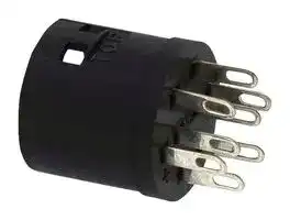


AL-C6
Socket, 16mm Miniature Switch & Pilot Light, Solder Lug, A6 Series
- Manufacturer: IDEC
- Product type: Industrial Switch Accessories
- SVHC: No SVHC (25-Jun-2025)
- For Use With: IDEC A6 Series 16mm Miniature Switches & Pilot Lights
- Product Range: A6 Series
- Accessory Type: Socket
| Delivery and price | |
|---|---|
| Units per pack | 50 |
| Price | 2.93 € |
| Current stock | 10+ |
| Lead time | 30 days |
ø16 Switches & Pilot Lights
Suitable for a wide variety of office and factory aplications.
## A6 Series
Features IDEC’s original mechanism for snap-action switching.
The LED lamp contains a current-limiting resistor and a diode for protection against reverse connection.
Degree of protection: IP40 and IP65 (IEC 60529)
Light duty in short 22 mm body length. Flush bezel accessories can be used to change A6 series to Flush Silhouette switches.
• CCC: Except pilot lights
• See website for details on approvals and standards.
## Standard Bezel
**==> picture [426 x 287] intentionally omitted <==**
**----- Start of picture text -----**<br>
[ Bezel size ] [ From panel front ] [ Shape ] [ Contact rating ] [ Action ] [ Operating stroke ]<br>ø18 18 18×24 9 Unibody Light<br>A6 OM | GF) tar<br>Illuminated Pushbuttons Pushbuttons Pilot Lights Selector Switches Key Selector Switches<br>6 6@¢ 6 @& @<br>eeeees<br>Flush Bezel<br>[ Bezel size ] [ From panel front ] [ Shape ] [ Contact rating ] [ Action ] [ Operating stroke ]<br>ø24 24 18×24 2 Unibody Light<br>A6 OMIM | CE) tar<br>Flush bezel accessories provide a sleek updated look. Enables downsizing of equipment.<br>Illuminated Pushbuttons Pushbuttons Pilot Lights Selector Switches Key Selector Switches<br>**----- End of picture text -----**<br>
B-147
ø16 A6 Series Miniature Switches & Pilot Lights ee
## Light duty in short 22mm body length.
APEM
Switches & Pilot Lights Control Boxes Emergency Stop Switches Enabling Switches Safety Products Explosion Proof Terminal Blocks Relays & Sockets Circuit Protectors Power Supplies
Circuit Specifications and Ratings Protectors Contact Ratings (Contact Block) Specifications Power Supplies Rated Insulation Voltage 250V Operating Temperature –25 to +55°C (no freezing) LED Illumination Rated Thermal Current 3A Storage Temperature –30 to +80°C (no freezing) Controllers Operating Voltage (AC/DC) 12V 24V 110V 220V Operating Humidity 45 to 85% RH (no condensation) AC 50/60 Hz Resistive Load — — 1.0A 0.5A Contact Resistance 50 mΩ maximum (initial value) Operator Interfaces Inductive Load — — 0.7A 0.5A Insulation Resistance 100 MΩ minimum (500V DC megger) Sensors Resistive Load 1.0A 1.0A 0.2A — Between live and dead metal parts: 2,000V AC, 1 minute DC Inductive Load 0.7A 0.7A 0.1A — Switch Unit Between terminals of different poles: 2,000V AC, 1 minute AUTO-ID Between terminals of the same pole: 1,000V AC, 1 minute Contact Material Gold plated silver Between contact and lamp terminals: 1,500V AC, 1 minute • Minimum applicable load: 5V AC/DC, 1 mA Illumination Unit Between live part and ground: 2,000V AC, 1 minute (applicable range may vary with operating conditions and load types) Vibration Resistance Operating extremes: 5 to 55 Hz, amplitude 0.75 mm Damage limits: 500 m/s[2] Flush Silhouette Shock Resistance Weight (example) Momentary: Operating extremes: 200 m/s1,000,000 operations[2] ø16 AL6M-M24: 8g Mechanical Durability Maintained: 100,000 operations ø22 AL6M-M221: 46g (minimum operations) Selector Switch: 250,000 operations AL6M-P4: 6g Key Selector Switch: 250,000 operations ø30 Other than Maintained: 100,000 operations Weight (approx.) AL6M-P21: 45g Electrical Durability Maintained: 50,000 operations Miniature AB6M-M2: 7g (minimum operations) (Switching frequency 1200 operations/h) AS6M-2Y2: 9g Degree of Protection IP40, IP65 (IEC 60529) Pilot Lights AS6M-2KT2A: 21g Terminal Style Solder terminal ~~—_=~~ LED Lamp Ratings (LATD) LB Rated Voltage 5V DC 12V AC/DC 24V AC/DC A6 Unit Voltage Range 5V DC ±5% 12V AC/DC ±10% 24V AC/DC ±10% Part No. LATD-5 ➁ N LATD-1 ➁ N LATD-2 ➁ N Lamp Base Exclusive for A series control units ~~—SSSSSSSS——~~ Current Draw 5 mA - Lamp Base Color Same as illumination color (except JW gray base) Voltage Marking Die stamped on the base LED Lamp Life (reference value) Approx. 50,000 hours (The luminance is reduced to 50% of the initial intensity when used on complete DC.) (+)X1 Limited current circuit X1 Limited current circuitNoise protection circuit Internal Circuit Noise protection circuit X2 Dimmer protection circuit X2 Rectifier circuit (–) Dimmer protection circuit ~~io~~ • Specify a color code in place of ➁ in the Part No. A (amber), G (green), JW (pure white), R (red), S (blue) • Use a pure white (JW) LED lamp for yellow illumination.
B-148
ø16 A6 Series Miniature Switches & Pilot Lights Illuminated Pushbuttons Quantity: 1 Operating Part No. ➁ Illumination Shape Operation Contact Voltage IP40 IP65 Color Code Round SPDT AL6M-M11➁ AL6M-M11P➁ AL6M 5V DC DPDT AL6M-M21➁ AL6M-M21P➁ SPDT AL6M-M13➁ AL6M-M13P➁ APEM Momentary 12V AC/DC DPDT AL6M-M23➁ AL6M-M23P➁ Switches & Pilot Lights SPDT AL6M-M14➁ AL6M-M14P➁ 24V AC/DC Control Boxes DPDT AL6M-M24➁ AL6M-M24P➁ ~~——~~ Emergency SPDT AL6M-A11➁ AL6M-A11P➁ Stop Switches 5V DC DPDT AL6M-A21➁ AL6M-A21P➁ Enabling Switches SPDT AL6M-A13➁ AL6M-A13P➁ Maintained 12V AC/DC Safety Products DPDT AL6M-A23➁ AL6M-A23P➁ SPDT AL6M-A14➁ AL6M-A14P➁ Explosion Proof 24V AC/DC DPDT AL6M-A24➁ AL6M-A24P➁ ~~~wi====~~ Terminal Blocks Square SPDT AL6Q-M11➁ AL6Q-M11P➁ AL6Q 5V DC Relays & Sockets DPDT AL6Q-M21➁ AL6Q-M21P➁ Circuit SPDT AL6Q-M13➁ AL6Q-M13P➁ Protectors Momentary 12V AC/DC DPDT AL6Q-M23➁ AL6Q-M23P➁ Power Supplies SPDT AL6Q-M14➁ AL6Q-M14P➁ 24V AC/DC LED Illumination DPDT AL6Q-M24➁ AL6Q-M24P➁ ~~===~~ Controllers SPDT AL6Q-A11➁ AL6Q-A11P➁ 5V DC DPDT AL6Q-A21➁ AL6Q-A21P➁ Operator Interfaces SPDT AL6Q-A13➁ AL6Q-A13P➁ Maintained 12V AC/DC Sensors DPDT AL6Q-A23➁ AL6Q-A23P➁ Specify a color code in place of ➁ in the Part No. AUTO-ID SPDT AL6Q-A14➁ AL6Q-A14P➁ 24V AC/DC DPDT AL6Q-A24➁ AL6Q-A24P➁ A: amber ~~j== ==~~ G: green Rectangular AL6H 5V DC DPDTSPDT AL6H-M11AL6H-M21➁➁ AL6H-M11PAL6H-M21P➁➁ JW: pure whiteR: red Flush Silhouette S: blue SPDT AL6H-M13➁ AL6H-M13P➁ Momentary 12V AC/DC Y: yellow ø16 DPDT AL6H-M23➁ AL6H-M23P➁ SPDT AL6H-M14➁ AL6H-M14P➁ ø22 24V AC/DC DPDT AL6H-M24➁ AL6H-M24P➁ ø30 SPDT AL6H-A11➁ AL6H-A11P➁ 5V DC Miniature DPDT AL6H-A21➁ AL6H-A21P➁ ~~|~~ SB SPDT AL6H-A13➁ AL6H-A13P➁ Pilot Lights Maintained 12V AC/DC DPDT AL6H-A23➁ AL6H-A23P➁ SPDT AL6H-A14➁ AL6H-A14P➁ 24V AC/DC DPDT AL6H-A24➁ AL6H-A24P➁ ~~_eee~~ LB Rectangular SPDT AL6G-M11➁ AL6G-M11P➁ w/three-sided barrier 5V DC A6 AL6G DPDT AL6G-M21➁ AL6G-M21P➁ SPDT AL6G-M13➁ AL6G-M13P➁ Momentary 12V AC/DC DPDT AL6G-M23➁ AL6G-M23P➁ ~~=| |[===]~~ SPDT AL6G-M14➁ AL6G-M14P➁ 24V AC/DC DPDT AL6G-M24➁ AL6G-M24P➁ SPDT AL6G-A11➁ AL6G-A11P➁ 5V DC DPDT AL6G-A21➁ AL6G-A21P➁ SPDT AL6G-A13➁ AL6G-A13P➁ Maintained 12V AC/DC DPDT AL6G-A23➁ AL6G-A23P➁ SPDT AL6G-A14➁ AL6G-A14P➁ 24V AC/DC DPDT AL6G-A24➁ AL6G-A24P➁ ~~eoEE=~~ • See B-151 for dimensions. • See B-166 for marking plate size and engraving area.
- IP65 types come with a packing in the lens unit.
- Illuminated switches have a built-in LED lamp.
B-149
ø16 A6 Series Miniature Switches & Pilot Lights
## Pilot Lights
|Shape<br>GS|Operating Voltage<br>|Part No.|Part No.|➁ Illumination<br>Color Code|
|---|---|---|---|---|
|||IP40<br>~~|~~<br>|IP65<br>~~|~~<br>||
|Round<br>AL6M-P<br>~~<br>GS~~|~~|5V DC<br>~~|_|~~<br>|AL6M-P1➁<br>~~|_|~~<br>~~|~~<br>|AL6M-P1P➁<br>~~|_|~~<br>~~|~~<br>|Specify a color code in place of<br>➁in the Part No.<br>A:<br>amber<br>G: green<br>JW: pure white<br>R:<br>red<br>S:<br>blue<br>Y:<br>yellow|
||12V AC/DC<br>~~|_|~~<br>~~|~~|AL6M-P3➁<br>~~|_|~~<br>~~|~~<br>~~|~~|AL6M-P3P➁<br>~~|_|~~<br>~~|~~<br>~~|~~||
||24V AC/DC<br>~~|~~<br>~~P|~~|AL6M-P4➁<br>~~|~~<br>~~|~~<br>~~P|~~|AL6M-P4P➁<br>~~|~~<br>~~|~~<br>~~P|~~||
|Square<br>AL6Q-P|5V DC<br>~~P|~~<br>~~P|~~|AL6Q-P1➁<br>~~P|~~<br>~~P|~~|AL6Q-P1P➁<br>~~P|~~<br>~~P|~~||
||12V AC/DC<br>~~P|~~<br>~~P|~~|AL6Q-P3➁<br>~~P|~~<br>~~P|~~|AL6Q-P3P➁<br>~~P|~~<br>~~P|~~||
||24V AC/DC<br>~~P|~~<br>~~P|~~|AL6Q-P4➁<br>~~P|~~<br>~~P|~~|AL6Q-P4P➁<br>~~P|~~<br>~~P|~~||
|Rectangular<br>AL6H-P<br>a.|5V DC<br>~~P|~~|AL6H-P1➁<br>~~P|~~|AL6H-P1P➁<br>~~P|~~||
||12V AC/DC<br>~~P|~~<br>~~P|~~<br>~~P|~~|AL6H-P3➁<br>~~P|~~<br>~~P|~~<br>~~P|~~|AL6H-P3P➁<br>~~P|~~<br>~~P|~~||
||24V AC/DC<br>~~P|~~<br>|AL6H-P4➁<br>~~P|~~<br>~~|~~<br>|AL6H-P4P➁<br>~~|~~<br>||
|Rectangular w/three-sided barrier<br>AL6G-P<br>.<br>a.|5V DC<br>~~P|~~<br>~~_]~~<br>|AL6G-P1➁<br>~~P|~~<br>~~_]~~<br>~~|~~<br>|AL6G-P1P➁<br>~~_]~~<br>~~|~~<br>||
||12V AC/DC<br>|AL6G-P3➁<br>~~|~~<br>|AL6G-P3P➁<br>~~|~~<br>||
||24V AC/DC<br> ~~P|~~|AL6G-P4➁<br>~~|~~<br>~~P|~~|AL6G-P4P➁<br>~~|~~<br>~~P|~~||
- See B-151 for dimensions.
- See B-166 for marking plate size and engraving area.
- Pilot lights have a built-in LED lamp.
B-150
ø16 A6 Series Miniature Switches & Pilot Lights
All dimensions in mm.
**==> picture [209 x 11] intentionally omitted <==**
**----- Start of picture text -----**<br>
Dimensions (Illuminated Pushbuttons & Pilot Lights)<br>**----- End of picture text -----**<br>
**==> picture [533 x 306] intentionally omitted <==**
**----- Start of picture text -----**<br>
Terminal Width 2.8×0.5t Rubber Gasket Panel Thickness 0.5 to 6<br>2.5 3 Anti-rotation Ring RectangularRectangular w/3-way barrier Square Round Ø18<br>Locking Ring<br>(TOP) (TOP) (TOP)<br>APEM<br>Switches & 6 6 1 0.6 24 �18 5.7<br>Pilot Lights 8 22 9 9<br>Control Boxes Pilot Light Illuminated Pushbutton<br>1.0 2.6<br>Emergency<br>Stop Switches<br>Enabling<br>Switches 2-R0.6<br>Safety Products * Solder/tab terminal<br>Explosion Proof<br>Terminal Blocks Terminal Arrangement (bottom view)<br>Illuminated Pushbutton Pilot Light<br>Relays & Sockets<br>(TOP) (TOP)<br>Circuit<br>Protectors NC1 NC2<br>Power Supplies<br>LED Illumination NO1 NO2<br>Controllers Lamp C1 C2 Lamp Lamp Lamp<br>Terminal (+) Terminal (–) Terminal (+) Terminal (–)<br>Operator<br>Interfaces 1NO: NC1, NO1, C1 terminal only<br>Sensors<br>5<br>18<br>5<br>1.2<br>**----- End of picture text -----**<br>
AUTO-ID
## Mounting Hole Layout
**==> picture [375 x 175] intentionally omitted <==**
**----- Start of picture text -----**<br>
Round/Square Rectangular<br>Flush Silhouette Rectangular w/3-way barrier<br>ø16.2 +0.20 ø16.2 +0.20<br>ø16<br>ø22 Note: Determine mounting centers to<br>ensure easy operation.<br>ø30<br>Miniature<br>Pilot Lights 18 min. 24 min.<br>LB<br>A6<br>18 min. 18 min.<br>**----- End of picture text -----**<br>
B-151
ø16 A6 Series Miniature Switches & Pilot Lights
## Pushbuttons
Quantity: 1
|Shape|Button Style|Operation|Contact|Part No.|Part No.|Color Code➀➁|
|---|---|---|---|---|---|---|
|||||IP40|IP65||
|Round<br>AB6M<br>~~ee~~<br>~~ewe~~|Button<br>~~ee~~|Momentary<br>~~ee~~|SPDT<br>~~ee~~|AB6M-M1➀<br>~~ee~~|AB6M-M1P➀<br>~~ee~~|B black<br>G: green<br>R: red<br>S: blue<br>W: white<br>Y:yellow<br>~~ee~~|
||||DPDT<br>~~ee~~|AB6M-M2➀<br>~~ee~~|AB6M-M2P➀<br>~~ee~~||
|||Maintained<br>~~ee~~|SPDT<br>~~ee~~|AB6M-A1➀<br>~~ee~~|AB6M-A1P➀<br>~~ee~~||
||||DPDT<br>~~ee~~|AB6M-A2➀<br>~~ee~~|AB6M-A2P➀<br>~~ee~~||
||Lens<br>~~ee~~<br>~~SS~~<br>~~ewe~~|Momentary<br>~~ee~~<br>~~SS~~|SPDT<br>~~ee~~<br>~~SS~~|AB6M-M1L➁<br>~~ee~~<br>~~SS~~|AB6M-M1PL➁<br>~~ee~~<br>~~SS~~|A: amber<br>G: green<br>R: red<br>S: blue<br>W: white<br>Y:yellow<br>~~ee~~<br>~~SS~~<br>|
||||DPDT<br>~~ee~~<br>~~SS~~|AB6M-M2L➁<br>~~ee~~<br>~~SS~~|AB6M-M2PL➁<br>~~ee~~<br>~~SS~~||
|||Maintained<br>~~ee~~<br>~~SS~~<br>~~ewe~~|SPDT<br>~~ee~~<br>~~SS~~|AB6M-A1L➁<br>~~ee~~<br>~~SS~~|AB6M-A1PL➁<br>~~ee~~<br>~~SS~~||
||||DPDT<br>~~ee~~<br>~~SS~~<br>|AB6M-A2L➁<br>~~ee~~<br>~~SS~~<br>|AB6M-A2PL➁<br>~~ee~~<br>~~SS~~<br>||
|Square<br>AB6Q<br>~~ewe~~<br>~~ese~~|Button<br>~~SS~~<br>~~ewe~~|Momentary<br>~~SS~~<br>~~ewe~~|SPDT<br>~~SS~~<br>|AB6Q-M1➀<br>~~SS~~<br>|AB6Q-M1P➀<br>~~SS~~<br>|B black<br>G: green<br>R: red<br>S: blue<br>W: white<br>Y:yellow<br>~~SS~~<br>|
||||DPDT<br>~~SS~~<br>|AB6Q-M2➀<br>~~SS~~<br>|AB6Q-M2P➀<br>~~SS~~<br>||
|||Maintained<br>~~ewe~~|SPDT<br>|AB6Q-A1➀<br>|AB6Q-A1P➀<br>||
||||DPDT<br>|AB6Q-A2➀<br>|AB6Q-A2P➀<br>||
||Lens<br>~~eweeS~~<br>~~ese~~|Momentary<br>~~eweeS~~|SPDT<br>~~eS~~|AB6Q-M1L➁<br>~~eS~~|AB6Q-M1PL➁<br>~~eS~~|A: amber<br>G: green<br>R: red<br>S: blue<br>W: white<br>Y:yellow<br>~~eS~~<br>|
||||DPDT<br>~~eS~~|AB6Q-M2L➁<br>~~eS~~|AB6Q-M2PL➁<br>~~eS~~||
|||Maintained<br>~~eweeS~~<br>~~ese~~|SPDT<br>~~eS~~|AB6Q-A1L➁<br>~~eS~~|AB6Q-A1PL➁<br>~~eS~~||
||||DPDT<br>~~eS~~<br>|AB6Q-A2L➁<br>~~eS~~<br>|AB6Q-A2PL➁<br>~~eS~~<br>||
|Rectangular<br>AB6H<br>~~ewe~~<br>~~ese~~|Button<br>~~eweeS~~<br>~~ese~~|Momentary<br>~~eweeS~~<br>~~ese~~|SPDT<br>~~eS~~<br>|AB6H-M1➀<br>~~eS~~<br>|AB6H-M1P➀<br>~~eS~~<br>|B black<br>G: green<br>R: red<br>S: blue<br>W: white<br>Y:yellow<br>~~eS~~<br>|
||||DPDT<br>~~eS~~<br>|AB6H-M2➀<br>~~eS~~<br>|AB6H-M2P➀<br>~~eS~~<br>||
|||Maintained<br>~~ese~~|SPDT<br>|AB6H-A1➀<br>|AB6H-A1P➀<br>||
||||DPDT<br>|AB6H-A2➀<br>|AB6H-A2P➀<br>||
||Lens<br>~~eseeS~~|Momentary<br>~~eseeS~~|SPDT<br>~~eS~~|AB6H-M1L➁<br>~~eS~~|AB6H-M1PL➁<br>~~eS~~|A: amber<br>G: green<br>R: red<br>S: blue<br>W: white<br>Y:yellow<br>~~eS~~|
||||DPDT<br>~~eS~~|AB6H-M2L➁<br>~~eS~~|AB6H-M2PL➁<br>~~eS~~||
|||Maintained<br>~~eseeS~~|SPDT<br>~~eS~~|AB6H-A1L➁<br>~~eS~~|AB6H-A1PL➁<br>~~eS~~||
||||DPDT<br>~~eS~~|AB6H-A2L➁<br>~~eS~~|AB6H-A2PL➁<br>~~eS~~||
|Rectangular<br>w/three-sided barrier<br>AB6G<br>~~ese~~<br>e~~.~~|Button<br>~~eseeS~~<br>~~.~~|Momentary<br>~~eseeS~~<br>|SPDT<br>~~eS~~<br>|AB6G-M1➀<br>~~eS~~<br>|AB6G-M1P➀<br>~~eS~~<br>|B black<br>G: green<br>R: red<br>S: blue<br>W: white<br>Y:yellow<br>~~eS~~<br>|
||||DPDT<br>~~eS~~<br>|AB6G-M2➀<br>~~eS~~<br>|AB6G-M2P➀<br>~~eS~~<br>||
|||Maintained<br>|SPDT<br>|AB6G-A1➀<br>|AB6G-A1P➀<br>||
||||DPDT<br>|AB6G-A2➀<br>|AB6G-A2P➀<br>||
||Lens<br>~~.EES~~|Momentary<br>~~EES~~|SPDT<br>~~EES~~|AB6G-M1L➁<br>~~EES~~|AB6G-M1PL➁<br>~~EES~~|A: amber<br>G: green<br>R: red<br>S: blue<br>W: white<br>Y:yellow<br>~~EES~~|
||||DPDT<br>~~EES~~|AB6G-M2L➁<br>~~EES~~|AB6G-M2PL➁<br>~~EES~~||
|||Maintained<br>~~EES~~|SPDT<br>~~EES~~|AB6G-A1L➁<br>~~EES~~|AB6G-A1PL➁<br>~~EES~~||
||||DPDT<br>~~EES~~|AB6G-A2L➁<br>~~EES~~|AB6G-A2PL➁<br>~~EES~~||
- Black is available for lens style buttons. Black lens consists of a clear lens and a black marking plate. Specify “B” in place of ➁ in the Part No. Example:AB6H-M2LB
B-152
ø16 A6 Series Miniature Switches & Pilot Lights
All dimensions in mm.
APEM
## Dimensions (Pushbuttons)
Switches & Pilot Lights
Control Boxes Emergency Stop Switches Enabling Switches Safety Products
**==> picture [472 x 160] intentionally omitted <==**
**----- Start of picture text -----**<br>
Pushbutton Rubber Gasket Panel Thickness 0.5 to 6<br>Terminal Width 2.8×0.5t<br>2.5 3 Anti-rotation Ring RectangularRectangular w/3-way barrier Square Round ø18<br>Locking Ring (TOP) (TOP) (TOP)<br>1 0.6 5.7<br>24 18<br>8 22 9 9<br>1.0 2.6<br>2-R0.6<br>* Solder/Tab Terminal<br>5<br>18<br>5<br>1.2<br>**----- End of picture text -----**<br>
Explosion Proof
- See B-164 for lens and button maintenance parts.
Terminal Blocks
Relays & Sockets
Circuit Protectors Power Supplies
**==> picture [463 x 130] intentionally omitted <==**
**----- Start of picture text -----**<br>
Protectors Mounting Hole Layout Terminal Arrangement (bottom view)<br>Power Supplies Round/Square Rectangular Pushbutton<br>w/3-way barrier<br>LED Illumination (TOP)<br>ø16.2 +0.20 ø16.2 +0.20<br>NC1 NC2<br>Controllers<br>Operator<br>Interfaces<br>NO1 NO2<br>Sensors<br>C1 C2<br>AUTO-ID<br>18 min. 24 min. Note: SPDT has only NC1, NO1, and C1 terminals.<br>18 min. 18 min.<br>**----- End of picture text -----**<br>
Note: Determine mounting centers to ensure easy operation.
Flush Silhouette
ø16 ø22 ø30 Miniature Pilot Lights
LB A6
B-153
ø16 A6 Series Miniature Switches & Pilot Lights
## Selector Switches MD
Operator position can be changed by IDEC’s original bezel rotating and locking system. The bezel can be locked at every 45° and bezel rotation is prevented while mounting on a panel. Example: 3-position
How to change the operator position
**==> picture [235 x 52] intentionally omitted <==**
**----- Start of picture text -----**<br>
R<br>R (C) L<br>(C) (C) L R (C)<br>L L R<br>Normal Operator Position<br>**----- End of picture text -----**<br>
Pull out the bezel to release the lock. Rotate the bezel, and push it in at 45° intervals to lock the bezel.
**==> picture [490 x 302] intentionally omitted <==**
**----- Start of picture text -----**<br>
|||||||||||||||||||
|---|---|---|---|---|---|---|---|---|---|---|---|---|---|---|---|---|---|
|Quantity: 1|
|Part No.|Contact Operation|
|Shape|Position|Contact|
|IP40|IP65|
|Round|SPDT|AS6M-2Y1|AS6M-2Y1P|Position|Operation|Left|Center|Right|
|AS6M-||Y|Maintained|pn|DPDT|AS6M-2Y2|AS6M-2Y2P|SPDT|
|SPDT|AS6M-21Y1|AS6M-21Y1P|L|R|NO|NC|NO|NC|
|Spring return from right to left|DPDT|AS6M-21Y2|AS6M-21Y2P|—|
|—==|Maintained|—eEeee|
|LEes|Maintained|DPDT|AS6M-3Y2|AS6M-3Y2P|—“|cae|C|C|
|Spring return from right to center|DPDT|AS6M-31Y2|AS6M-31Y2P|DPDT|
|es|So|
|Spring return from left to center|DPDT|AS6M-32Y2|AS6M-32Y2P|L|R|ContactLeft|ContactRight|ContactLeft|ContactRight|
|es|Spring return two-way|DPDT|AS6M-33Y2|AS6M-33Y2P|2|i ayy|NO|NC|NO|NC|—|NO|NC|_|NO|NC|
|Square|SPDT|AS6Q-2Y1|AS6Q-2Y1P|Spring return|
|AS6Q-||Y|Maintained|DPDT|AS6Q-2Y2|AS6Q-2Y2P|from right|C|C|C|C|
|||SPDT|AS6Q-21Y1|AS6Q-21Y1P|L|C|R|DPDT|
|Spring return from right to left|
|EEee|DPDT|AS6Q-21Y2|AS6Q-21Y2P|<>|cee|
|es|Maintained|DPDT|AS6Q-3Y2|AS6Q-3Y2P|Maintained|
|es|Spring return from right to center|DPDT|AS6Q-31Y2|AS6Q-31Y2P|L|C|R|
|Spring return from left to center|DPDT|AS6Q-32Y2|AS6Q-32Y2P|
|RectangularAS6H-||Y|Sees|Spring return two-way Maintained|DPDTDPDTSPDT|AS6Q-33Y2AS6H-2Y2AS6H-2Y1|AS6Q-33Y2PAS6H-2Y1PAS6H-2Y2P|Spring return from right L|VV|C|R|NOContactLeftNC|NOContactRightNC|NOContactLeftNC|NOContactRightNC|NOContactLeftNC|NOContactRightNC|
|Spring return from right to left|SPDT|AS6H-21Y1|AS6H-21Y1P|Spring return|C|C|C|C|C|C|
|-PEErr|DPDT|AS6H-21Y2|AS6H-21Y2P|from left|VY|VOP|EE|EY|
|a|Maintained|DPDT|AS6H-3Y2|AS6H-3Y2P|C|
|L|R|
|Spring return from right to center|DPDT|AS6H-31Y2|AS6H-31Y2P|
|es|Spring return from left to center|DPDT|AS6H-32Y2|AS6H-32Y2P|Two-way|
|ans|Spring return two-way|DPDT|AS6H-33Y2|AS6H-33Y2P|return|<p|
**----- End of picture text -----**<br>
• Bezel: black • Knob: black
APEM
Switches & Pilot Lights Control Boxes Emergency Stop Switches Enabling Switches Safety Products Explosion Proof Terminal Blocks Relays & Sockets Circuit Protectors Power Supplies LED Illumination Controllers Operator Interfaces Sensors AUTO-ID
Flush Silhouette ø16 ø22 ø30 Miniature Pilot Lights
LB A6
B-154
ø16 A6 Series Miniature Switches & Pilot Lights
All dimensions in mm.
APEM
Emergency Stop Switches Enabling Switches
Operator Interfaces Sensors AUTO-ID
## Dimensions (Selector Switches)
Switches & Pilot Lights Control Boxes
## Dimensions
All dimensions in mm.
**==> picture [470 x 105] intentionally omitted <==**
**----- Start of picture text -----**<br>
Panel Thickness 0.5 to 6<br>Terminal Width 2.8×0.5t Rubber Gasket<br>2.5 3 Anti-rotation Ring Rectangular(TOP) Square(TOP) Round(TOP)<br>Locking Ring<br>1 8<br>8 22 15.5 24 �18<br>ø18<br>5<br>18<br>5<br>**----- End of picture text -----**<br>
Safety Products
Explosion Proof
Terminal Blocks
Relays & Sockets Circuit Protectors Power Supplies LED Illumination
Controllers
## Terminal Arrangement (bottom view)
## (Selector Switch)
**==> picture [61 x 70] intentionally omitted <==**
**----- Start of picture text -----**<br>
(TOP)<br>NC1 NC2<br>NO1 NO2<br>C1 C2<br>**----- End of picture text -----**<br>
SPDT has NC1, NO1, and C1 only.
## Mounting Hole Layout
**==> picture [248 x 101] intentionally omitted <==**
**----- Start of picture text -----**<br>
Round/Square Rectangular<br>+0.2 +0.2<br>ø16.2 0 ø16.2 0<br>18 min. 24 min.<br>18 min. 18 min.<br>**----- End of picture text -----**<br>
Note: Determine mounting centers to ensure easy operation.
Flush Silhouette ø16 ø22 ø30 Miniature Pilot Lights
LB A6
B-155
ø16 A6 Series Miniature Switches & Pilot Lights
~~eee~~ Key Selector Switches (Round) Quantity: 1
|Shape<br>~~ee~~|Position<br>~~ee~~|Operation<br>~~ee~~|Key Retained<br>at ●<br>~~ee~~<br>~~|~~|Key Retained<br>at ●<br>~~ee~~<br>~~|~~|Contact<br>~~ee~~<br>|Part No.<br>~~ee~~|Part No.<br>~~ee~~|
|---|---|---|---|---|---|---|---|
|||||||IP40<br>~~ee~~<br>|IP65<br>~~ee~~<br>~~ee~~<br>|
|Round<br>AS6M<br>.<br>&<br>»)|90°<br>2-position<br>~~eo~~|Maintained<br>~~eo~~|A<br>~~0~~<br>~~|~~|L<br>R<br>~~eee~~<br>~~ke~~|SPDT<br>~~eee~~<br>|AS6M-2KT1A<br>~~eee~~<br>|AS6M-2KT1PA<br>~~eee~~<br>~~ee~~<br>|
||||||DPDT<br>~~eee~~<br>~~re~~|AS6M-2KT2A<br>~~eee~~<br>~~re~~|AS6M-2KT2PA<br>~~eee~~<br>~~ee~~<br>~~re~~|
||||B<br>~~|~~|L<br>R<br>~~ke~~|SPDT<br>~~re~~|AS6M-2KT1B<br>~~re~~|AS6M-2KT1PB<br>~~ee~~<br>~~re~~|
||||||DPDT<br>~~re~~|AS6M-2KT2B<br>~~re~~|AS6M-2KT2PB<br>~~ee~~<br>~~re~~|
||||C<br>~~| ~~<br>~~|e~~|L<br>R<br> ~~ke~~<br>~~|e~~|SPDT<br>~~re~~<br>~~|e~~|AS6M-2KT1C<br>~~re~~<br>~~|e~~|AS6M-2KT1PC<br>~~ee~~<br>~~re~~<br>~~|e~~|
||||||DPDT<br>~~re~~<br>~~|e~~|AS6M-2KT2C<br>~~re~~<br>~~|e~~|AS6M-2KT2PC<br>~~re~~<br>~~|e~~<br>~~—~~|
|||Spring return from right<br>~~eo~~|B<br>~~|e~~|L<br>R<br>~~|e~~|SPDT<br>~~|e~~|AS6M-21KT1B<br>~~|e~~|AS6M-21KT1PB<br>~~|e~~<br>~~—~~|
||||||DPDT<br>~~|e~~|AS6M-21KT2B<br>~~|e~~|AS6M-21KT2PB<br>~~|e~~<br>~~—~~|
||45°<br>3-position<br>~~eo~~|Maintained<br>~~eo~~|A<br>~~|e~~<br>~~ee~~<br>~~jeyi]~~|L<br>C<br>R<br>~~|e~~<br>~~ee~~<br>~~jeyi]~~|DPDT<br>~~|e~~<br>~~ee~~<br>~~jeyi]~~<br>~~|~~|AS6M-3KT2A<br>~~|e~~<br>~~ee~~<br>~~jeyi]~~<br>~~||~~|AS6M-3KT2PA<br>~~|e~~<br>~~—~~<br>~~ee~~<br>~~jeyi]~~<br>~~|~~|
||||B<br>~~jeyi]~~|L<br>C<br>R<br>~~jeyi]~~|DPDT<br>~~jeyi]~~<br>~~|~~|AS6M-3KT2B<br>~~jeyi]~~<br>~~||~~<br>~~ee~~|AS6M-3KT2PB<br>~~jeyi]~~<br>~~|~~|
||||C<br>~~jeyi]~~<br>~~ee~~<br>~~ini)~~|C<br>R<br>L<br>~~jeyi]~~<br>~~ee~~<br>~~ini)~~|DPDT<br>~~jeyi]~~<br>~~|~~<br>~~ee~~<br>~~ini)~~|AS6M-3KT2C<br>~~jeyi]~~<br>~~| |~~<br>~~ee~~<br>~~ee~~<br>~~|~~|AS6M-3KT2PC<br>~~jeyi]~~<br>~~|~~<br>~~ee~~<br>~~|~~|
||||D<br>~~ee~~<br>~~ini)~~<br>~~ee~~|C<br>R<br>L<br>~~ee~~<br>~~ini)~~<br>~~ee~~|DPDT<br>~~ee~~<br>~~ini)~~<br>~~ee~~|AS6M-3KT2D<br>~~ee~~<br>~~ee~~<br>~~|~~<br>~~ee~~|AS6M-3KT2PD<br>~~ee~~<br>~~|~~|
||||E<br>~~ini)~~<br>~~ee~~|L<br>R<br>C<br>~~ini)~~<br>~~ee~~|DPDT<br>~~ini) ~~<br>~~ee~~|AS6M-3KT2E<br> ~~|~~<br>~~ee~~|AS6M-3KT2PE<br>~~|~~|
||||G<br>~~ee~~<br>~~ey~~<br>~~Se~~|L<br>C<br>R<br>~~ee~~<br>~~ey~~<br>~~Se~~|DPDT<br>~~ee~~<br>~~ey~~<br>~~|~~|AS6M-3KT2G<br>~~ee~~<br>~~ey~~<br>~~|~~|AS6M-3KT2PG<br>~~ey~~<br>~~|~~|
||||H<br>~~ey~~<br>~~Se~~|C<br>L<br>R<br>~~ey~~<br>~~Se~~|DPDT<br>~~ey~~<br>~~|~~|AS6M-3KT2H<br>~~ey~~<br>~~|~~|AS6M-3KT2PH<br>~~ey~~<br>~~|~~|
|||Spring return from right|B<br>~~Se~~<br>~~Ne~~|C<br>L<br>R<br>~~Se ~~<br>~~Ne~~|DPDT<br> ~~|~~<br>~~Ne~~|AS6M-31KT2B<br>~~|~~<br>~~ee~~|AS6M-31KT2PB<br>~~|~~<br>~~ee~~|
||||D<br>~~Ne~~<br>~~Ne~~<br>~~i~~|C<br>R<br>L<br>~~Ne~~<br>~~Ne~~<br>~~ee~~|DPDT<br>~~Ne ~~<br>~~Ne~~<br>~~ee~~|AS6M-31KT2D<br> ~~ee~~<br>~~Ne~~<br>~~ee~~|AS6M-31KT2PD<br>~~ee~~<br>~~Ne~~|
||||G<br>~~Ne~~<br>~~i~~<br>~~iN)~~|L<br>C<br>R<br>~~Ne~~<br>~~ee~~<br>~~iN)~~|DPDT<br>~~Ne~~<br>~~ee~~<br>~~iN)|)~~|AS6M-31KT2G<br>~~Ne~~<br>~~ee~~<br>~~|)~~|AS6M-31KT2PG<br>~~Ne~~<br>~~|)~~|
|||Spring return from left<br>~~a~~|C<br>~~i~~<br>~~iN)~~<br>~~oNf4~~|C<br>R<br>L<br>~~ee~~<br>~~iN)~~<br>~~oNf4~~|DPDT<br>~~ee ~~<br>~~iN)|)~~<br>|AS6M-32KT2<br> ~~ee~~<br>~~|)~~<br>|AS6M-32KT2PC<br>~~|)~~<br>|
||||D<br>~~iN)~~<br>~~oNf4~~|C<br>R<br>L<br>~~iN)~~<br>~~oNf4~~|DPDT<br>~~iN) |)~~<br>|AS6M-32KT2D<br>~~|)~~<br>|AS6M-32KT2PD<br>~~|)~~<br>|
||||H<br>~~oNf4oN)~~|C<br>L<br>R<br>~~oNf4oN)~~<br>~~ee~~|DPDT<br>~~oN)~~<br>~~ee~~|AS6M-32KT2H<br>~~oN)~~<br>~~ee~~|AS6M-32KT2PH<br>~~oN)~~<br>~~ee~~|
|||Spring return two-way<br>~~a~~|D<br>~~oN)~~|C<br>R<br>L<br>~~oN)~~<br>~~ee~~|DPDT<br>~~oN)~~<br>~~ee~~|AS6M-33KT2D<br>~~oN)~~<br>~~ee~~|AS6M-33KT2PD<br>~~oN)~~<br>~~ee~~|
- Key is retained at ● positions and removable at positions.
- Two keys are supplied.
- The front of key cylinder is made of metal.
- Disc tumbler key. Only one key number is available.
## Contact Operation
**==> picture [493 x 153] intentionally omitted <==**
**----- Start of picture text -----**<br>
Operator Position & Contact Operation (Top View)<br>Positions Contact Left Center Right<br>NO NC NO NC<br>SPDT —<br>L R L R C C<br>90° 2-position ContactLeft ContactRight ContactLeft ContactRight<br>Maintained VY Spring return from right tet] NO NC NO NC ps NO NC NO NC<br>DPDT —<br>C C C C<br>C C C C Left Right Left Right Left Right<br>|| L R L R L V? R L R eich Contact Contact Contact Contact Contact Contact<br>NO NC NO NC NO NC NO NC NO NC NO NC<br>45° 3-position DPDT<br>Maintained Spring return Spring return Spring return<br>PIV from right VY from left two-way OT Lye C C fee C C fee C C<br>**----- End of picture text -----**<br>
B-156
ø16 A6 Series Miniature Switches & Pilot Lights ~~eee~~ Key Selector Switches (Square) Quantity: 1 Key Retained Part No. Shape Position Operation Contact at ● IP40 IP65 Square A L R SPDT AS6Q-2KT1A AS6Q-2KT1PA ~~SS~~ AS6Q DPDT AS6Q-2KT2A AS6Q-2KT2PA ~~|e~~ L R SPDT ~~ee~~ AS6Q-2KT1B AS6Q-2KT1PB APEM Maintained B Switches & 90° DPDT AS6Q-2KT2B AS6Q-2KT2PB ~~=~~ Pilot Lights 2-position ~~|~~ L R ~~ee~~ SPDT AS6Q-2KT1C AS6Q-2KT1PC C Control Boxes DPDT AS6Q-2KT2C AS6Q-2KT2PC ~~[Mee~~ Emergency L R SPDT AS6Q-21KT1B AS6Q-21KT1PB Oo Stop Switches Spring return from right B Cs ~~a~~ DPDT AS6Q-21KT2B AS6Q-21KT2PB Enabling Switches A L C R DPDT AS6Q-3KT2A AS6Q-3KT2PA Safety Products ~~——~~ Explosion Proof ~~ee~~ B L C R DPDT ~~ee~~ AS6Q-3KT2B AS6Q-3KT2PB ~~a~~ Terminal Blocks ~~ke}~~ C L C R DPDT AS6Q-3KT2C AS6Q-3KT2PC ~~=~~ Relays & SocketsCircuit Maintained ~~ee~~ D L C R DPDT ~~eee~~ AS6Q-3KT2D AS6Q-3KT2PD Protectors ~~|~~ Power Supplies ~~Net~~ E L C R DPDT ~~||~~ AS6Q-3KT2E AS6Q-3KT2PE ~~a~~ LED Illumination G L C R DPDT AS6Q-3KT2G AS6Q-3KT2PG ~~—_~~ Controllers & ~~a~~ ~~**e**~~ Operator | ~~a~~ H L C R ~~2e~~ DPDT AS6Q-3KT2H AS6Q-3KT2PH ~~e~~ Interfaces 45° ~~a~~ Sensors 3-position ~~Sey~~ B L C R ~~|~~ DPDT AS6Q-31KT2B AS6Q-31KT2PB ~~— Ne~~ AUTO-ID C ~~ee~~ Spring return from right D L R DPDT AS6Q-31KT2D AS6Q-31KT2PD ~~— Ne}~~ G L C R DPDT ~~|~~ AS6Q-31KT2G AS6Q-31KT2PG ~~— i~~ Flush Silhouette C C L R DPDT AS6Q-32KT2C AS6Q-32KT2PC ø16 ~~—~~ ø22 Spring return from left ~~ost~~ D L C R DPDT ~~||~~ AS6Q-32KT2D AS6Q-32KT2PD ~~—~~ ø30 ~~oN)~~ L C R H DPDT AS6Q-32KT2H AS6Q-32KT2PH ~~ee~~ Miniature Spring return two-way ~~we)~~ D L C R DPDT ~~||~~ AS6Q-33KT2D AS6Q-33KT2PD ~~—~~ Pilot Lights ~~es~~ • Key is retained at ● positions and removable at positions. • Two keys are supplied. • The front of key cylinder is made of metal. LB • Disc tumbler key. Only one key number is available. A6 ~~|~~ Contact Operation Operator Position & Contact Operation (Top View) Positions Contact Left Center Right NO NC NO NC SPDT — L R L R C C 90° 2-position ContactLeft ContactRight ContactLeft ContactRight Maintained VY Spring return from right ~~fet]~~ NO NC NO NC ~~ps~~ NO NC NO NC DPDT — C C C C C C C C Left Right Left Right Left Right ~~|~~ L R L R L ~~?~~ R L R ~~eich~~ Contact Contact Contact Contact Contact Contact NO NC NO NC NO NC NO NC NO NC NO NC 45° 3-position DPDT Maintained Spring return Spring return Spring return ~~Pee~~ from right from left two-way ~~bela~~ C C C C C C
B-157
ø16 A6 Series Miniature Switches & Pilot Lights
~~eee~~ Key Selector Switches (Rectangular)
APEM Switches & Pilot Lights Control Boxes Emergency Stop Switches Enabling Switches Safety Products Explosion Proof Terminal Blocks Relays & Sockets Circuit Protectors Power Supplies LED Illumination Controllers Operator Interfaces Sensors AUTO-ID Flush Silhouette ø16 ø22 ø30 Miniature Pilot Lights LB A6
|Shape<br>~~ee~~|Position<br>~~ee~~|Operation<br>~~ee~~|Key Retained<br>at ●<br>~~ee~~<br>~~eee~~|Key Retained<br>at ●<br>~~ee~~<br>~~eee~~|Contact<br>~~ee~~<br>~~eee~~|Part No.<br>~~ee~~<br>~~eee~~|Part No.<br>~~ee~~<br>~~eee~~|
|---|---|---|---|---|---|---|---|
|||||||IP40<br>~~ee~~<br>~~eee~~|IP65<br>~~ee~~<br>~~eee~~|
|Rectangular<br>AS6H<br>;<br>=|90°<br>2-position|Maintained<br>~~A~~|A<br>~~eee~~<br>~~A~~<br>~~|~~|L<br>R<br>~~eee~~<br>~~A~~<br>~~ke~~|SPDT<br>~~eee~~<br>~~eee~~|AS6H-2KT1A<br>~~eee~~<br>~~eee~~|AS6H-2KT1PA<br>~~eee~~<br>~~eee~~|
||||||DPDT<br>~~eee~~<br>|AS6H-2KT2A<br>~~eee~~<br>|AS6H-2KT2PA<br>~~eee~~<br>|
||||B<br>~~|~~|L<br>R<br>~~ke~~|SPDT<br>|AS6H-2KT1B<br>|AS6H-2KT1PB<br>|
||||||DPDT<br>|AS6H-2KT2B<br>|AS6H-2KT2PB<br>|
||||C<br>~~| |e~~<br>~~A~~|L<br>R<br> ~~ke|e~~<br>~~A~~|SPDT<br>~~|e~~|AS6H-2KT1C<br>~~|e~~|AS6H-2KT1PC<br>~~|e~~|
||||||DPDT<br>~~|e~~<br>~~ee~~|AS6H-2KT2C<br>~~|e~~<br>~~ee~~|AS6H-2KT2PC<br>~~|e~~|
|||Spring return from right<br>~~A~~|B<br>~~A~~|L<br>R<br>~~A~~|SPDT<br>~~ee~~|AS6H-21KT1B<br>~~ee~~|AS6H-21KT1PB|
||||||DPDT<br>~~ee~~|AS6H-21KT2B<br>~~ee~~|AS6H-21KT2PB|
||45°<br>3-position|Maintained<br>~~A~~|A<br>~~A~~<br>~~ee~~|L<br>C<br>R<br>~~A ~~<br>~~ee~~|DPDT<br> ~~ee~~<br>~~ee~~<br>~~|~~|AS6H-3KT2A<br>~~ee~~<br>~~ee~~<br>~~||~~|AS6H-3KT2PA<br>~~ee~~<br>~~|~~|
||||B<br>~~ee~~<br>~~jay]~~|L<br>C<br>R<br>~~ee~~<br>~~jay]~~|DPDT<br>~~ee~~<br>~~jay]~~<br>~~|~~|AS6H-3KT2B<br>~~ee~~<br>~~jay]~~<br>~~||~~|AS6H-3KT2PB<br>~~ee~~<br>~~jay]~~<br>~~|~~|
||||C<br>~~jay]~~<br>~~iNet~~<br>~~iN)~~|C<br>R<br>L<br>~~jay]~~<br>~~iNet~~<br>~~iN)~~|DPDT<br>~~jay]~~<br>~~|~~<br>~~iNet~~<br>~~iN)||~~|AS6H-3KT2C<br>~~jay]~~<br>~~| |~~<br>~~iNet~~<br>~~||~~|AS6H-3KT2PC<br>~~jay]~~<br>~~|~~<br>~~iNet~~<br>~~||~~|
||||D<br>~~iNet~~<br>~~iN)~~<br>~~**2**~~|C<br>R<br>L<br>~~iNet~~<br>~~iN)~~<br>~~**2**~~|DPDT<br>~~iNet~~<br>~~iN)||~~|AS6H-3KT2D<br>~~iNet~~<br>~~||~~<br>~~ee~~|AS6H-3KT2PD<br>~~iNet~~<br>~~||~~<br>~~ee~~|
||||E<br>~~iN)~~<br>~~**2**~~|L<br>R<br>C<br>~~iN)~~<br>~~**2**~~|DPDT<br>~~iN) ||~~|AS6H-3KT2E<br>~~||~~<br>~~ee~~<br>~~ee~~|AS6H-3KT2PE<br>~~||~~<br>~~ee~~|
||||G<br>~~**2**~~|L<br>C<br>R<br>~~**2**~~|DPDT|AS6H-3KT2G<br>~~ee~~<br>~~ee~~|AS6H-3KT2PG<br>~~ee~~|
||||H<br>~~**2**~~<br>~~Ne~~|C<br>L<br>R<br>~~**2**~~<br>~~Ne~~|DPDT<br>~~Ne~~|AS6H-3KT2H<br>~~ee ~~<br>~~ee~~<br>~~Ne~~|AS6H-3KT2PH<br> ~~ee~~<br>~~Ne~~|
|||Spring return from right|B<br>~~Ne~~|C<br>L<br>R<br>~~Ne~~|DPDT<br>~~Ne ee~~|AS6H-31KT2B<br>~~ee~~|AS6H-31KT2PB<br>~~ee~~|
||||D<br>~~Ne~~<br>~~Ne~~|C<br>R<br>L<br>~~Ne~~<br>~~Ne~~|DPDT<br>~~Ne ee~~<br>~~Ne~~|AS6H-31KT2D<br>~~ee~~<br>~~Ne~~|AS6H-31KT2PD<br>~~ee~~<br>~~Ne~~|
||||G<br>~~Ne~~<br>~~ee~~<br>~~iN)~~|L<br>C<br>R<br>~~Ne~~<br>~~ee~~<br>~~iN)~~|DPDT<br>~~Ne~~<br>~~ee~~<br>~~iN)||~~|AS6H-31KT2G<br>~~Ne~~<br>~~ee~~<br>~~||~~|AS6H-31KT2PG<br>~~Ne~~<br>~~ee~~<br>~~||~~|
|||Spring return from left<br>~~es~~|C<br>~~ee~~<br>~~iN)~~|C<br>R<br>L<br>~~ee~~<br>~~iN)~~|DPDT<br>~~ee~~<br>~~iN)||~~|AS6H-32KT2C<br>~~ee~~<br>~~||~~|AS6H-32KT2PC<br>~~ee~~<br>~~||~~|
||||D<br>~~iN)~~<br>~~Ne~~|C<br>R<br>L<br>~~iN)~~<br>~~Ne~~|DPDT<br>~~iN) ||~~<br>~~Ne~~|AS6H-32KT2D<br>~~||~~<br>~~Ne~~|AS6H-32KT2PD<br>~~||~~<br>~~Ne~~|
||||H<br>~~Ne~~<br>~~oN~~|C<br>L<br>R<br>~~Ne~~<br>~~oN~~|DPDT<br>~~Ne~~<br>~~oN~~|AS6H-32KT2H<br>~~Ne~~<br>~~oN~~|AS6H-32KT2PH<br>~~Ne~~<br>~~oN~~|
|||Spring return two-way<br>~~es~~|D<br>~~oN~~|C<br>R<br>L<br>~~oN~~|DPDT<br>~~oN~~|AS6H-33KT2D<br>~~oN~~|AS6H-33KT2PD<br>~~oN~~|
- Key is retained at ● positions and removable at positions.
- Two keys are supplied.
- The front of key cylinder is made of metal.
- Disc tumbler key. Only one key number is available.
## Contact Operation
**==> picture [493 x 153] intentionally omitted <==**
**----- Start of picture text -----**<br>
Operator Position & Contact Operation (Top View)<br>Positions Contact Left Center Right<br>NO NC NO NC<br>SPDT —<br>L R L R C C<br>90° 2-position ContactLeft ContactRight ContactLeft ContactRight<br>Maintained VY Spring return from right tet] NO NC NO NC ps NO NC NO NC<br>DPDT —<br>C C C C<br>C C C C Left Right Left Right Left Right<br>|| L R L R L V? R L R eich Contact Contact Contact Contact Contact Contact<br>NO NC NO NC NO NC NO NC NO NC NO NC<br>45° 3-position DPDT<br>Maintained Spring return Spring return Spring return<br>PIV from right VY from left two-way OT Lye C C fee C C fee C C<br>**----- End of picture text -----**<br>
B-158
ø16 A6 Series Miniature Switches & Pilot Lights
All dimensions in mm.
## Dimensions
APEM Switches & Pilot Lights
Control Boxes
Emergency Stop Switches Enabling Switches Safety Products
**==> picture [442 x 148] intentionally omitted <==**
**----- Start of picture text -----**<br>
Right Contact<br>1.0 2.6<br>Left Contact 2-R0.6<br>Terminal Width 2.8×0.5t Rubber Gasket Panel Thickness 0.5 to 6<br>Anti-rotation Ring Round Square Rectangular<br>2.5 3 (TOP) (TOP) (TOP)<br>Locking Ring<br>NC<br>NO<br>C<br>1<br>9<br>8 22 26 ø18 18 24<br>2.5<br>TOP<br>3 1.2<br>5<br>18<br>5<br>**----- End of picture text -----**<br>
Explosion Proof
## Mounting Hole Layout
Terminal Arrangement (bottom view) (Key Selector Switch)
Terminal Blocks
**==> picture [370 x 104] intentionally omitted <==**
**----- Start of picture text -----**<br>
Relays & Sockets Round/Square Rectangular (Key Selector Switch)<br>Circuit ø16.2 +0.20 ø16.2 +0.20 (TOP)<br>Protectors<br>NC1 NC2<br>Power Supplies<br>LED Illumination<br>NO1 NO2<br>Controllers<br>C1 C2<br>Operator<br>Interfaces 18 min. 24 min.<br>18 min. 18 min.<br>**----- End of picture text -----**<br>
**==> picture [100 x 8] intentionally omitted <==**
**----- Start of picture text -----**<br>
SPDT has NC1, NO1, and C1 only.<br>**----- End of picture text -----**<br>
Sensors
Note: Determine mounting centers to ensure easy operation.
AUTO-ID
## Spare Key
**==> picture [144 x 92] intentionally omitted <==**
**----- Start of picture text -----**<br>
Flush Silhouette 8.1 17 t =1.8<br>ø16<br>ø22<br>ø30<br>Miniature<br>Pilot Lights Key No.<br>ø3.0<br>7 18<br>∗<br>**----- End of picture text -----**<br>
LB
A6
B-159
ø16 A6 Series Miniature Switches & Pilot Lights
Accessories All dimensions in mm.
Shape Material Part No. Quantity Remarks ~~eeee ee ee ee~~ Locking Ring Wrench ø18 Metal • Used to tighten the locking ring when installing A6 (nickel-plated MT-001 1 control units into a panel. 60 brass) APEM ~~FF| ll~~ Lamp Holder Tool ø9 Switches & ø10 Nitryl Rubber OR-77 1 • Used to install and remove the LED lamps. Pilot Lights 55 Control Boxes ~~we~~ Lens Removal Tool Emergency Stop Switches Stainless Steel MT-101 1 • Used to install and remove lenses and buttons. Enabling 60 Switches ~~ee~~ [Maintained} Safety Products For round/ • Degree of protection: IP40 For pushbuttons, illuminated square units LB9Z-K2 1 • Used to protect pushbuttons from inadvertent Explosion Proof pushbuttons (110°, 180°) operation. Terminal Blocks For rectangular • Degree of protection: IP65 Relays & Sockets LB9Z-K3P 1 • Used to protect pushbuttons from inadvertent units (remains Circuit 110°, 180°) operation. Protectors ~~a8rT~~ ~~**P** f fof,~~ Guard [Spring return] • Degree of protection: IP40 Power Supplies :polyacetal For pushbuttons, illuminated For round/ Cover AL-K6S 1 • Used to protect pushbuttons from inadvertent operation. LED Illumination pushbuttons square units :polyarylate • Degree of protection: IP65 (when used with IP65 Controllers (180°) See B-161 for AL-K6SP 1 control units) Operator • Used to protect pushbuttons from inadvertent Interfaces dimen sions. operation. Sensors • Degree of protection: IP40 a ~~Te~~ AL-KH6S 1 • Used to protect pushbuttons from inadvertent AUTO-ID For operation. rectangular • Degree of protection: IP65 (when used with IP65 units (180°) control units) AL-KH6SP 1 • Used to protect pushbuttons from inadvertent Flush Silhouette ~~- w) E~~ operation. ~~P~~ ø16 Dust Cover ➀ For round units Translucent cover: AL-D6 1 elastomer • When mounting the control units with the dust ø22 ➀ ➁ ➂ ➁ For square units Rear/black part: polypropylene AL-DQ6 1 covers installed, refer to mounting hole layout on B-162. ø30 ➂ For rectangular units See dimen sions.B-161 for AL-DH6 1 • Operating temperature: –10 to +55°C Miniature ~~eam~~ Pilot Lights Terminal Cover Polyamide (white) • When wiring the terminals, insert the lead wires into the terminal cover holes before soldering. AL-V6 10 See B-162 for • Terminal cover is not attached and must be ordered dimen sions. separately. LB Socket ➀ Enclosure: A6 ➀ Solder Polyamide (black) AL-C6 1 Terminal ~~pte~~ Terminal block: ~~ie~~ • Plugs on the rear of the A series control units. ➁ Brass/zinc-plated ➁ PC Board See B-162 for AL-C6V 1 Terminal ~~oe~~ dimen sions. Mounting Hole Plug • Degree of protection: IP65 2 6 Nitryl rubber Rubber AL-B6 5 (black) ~~ee~~ Mounting Hole Plug ~~OB~~ • Degree of protection: IP65 Plug: metal • Tightening torque: 0.1 to 0.29 N·m. (diecast) 2.5 12 Locking ring: Metal AL-BM6 1 polyacetal Gasket: nitryl rubber Gasket Locking Ring Panel Thickness 0.5 to 6 ~~eeeee~~ NIDEC B-160 Mounting Hole Mounting Hole
ø16 A6 Series Miniature Switches & Pilot Lights
All dimensions in mm.
APEM
Switches & Pilot Lights Control Boxes Emergency Stop Switches Enabling Switches Safety Products Explosion Proof Terminal Blocks
Relays & Sockets
Circuit Protectors Power Supplies
LED Illumination
Controllers
Operator Interfaces Sensors AUTO-ID
## Dimensions
## Switch Guard
## [Remains open]
For round/square units (Degree of protection: IP40) LB9Z-K2
**==> picture [221 x 116] intentionally omitted <==**
**----- Start of picture text -----**<br>
Panel Thickness<br>0.5 to 5.6 32.7<br>Rubber Gasket 18<br>12.4<br>180°<br>110°<br>32.9<br>11 13<br>23.5<br>**----- End of picture text -----**<br>
For rectangular units (Degree of protection: IP65) LB9Z-K3P
**==> picture [227 x 116] intentionally omitted <==**
**----- Start of picture text -----**<br>
Panel Thickness<br>0.5 to 5.6 32.7<br>Rubber Gasket<br>24<br>12.4<br>180°<br>110°<br>32.9<br>11 13<br>23.5<br>**----- End of picture text -----**<br>
## [Spring return]
For round/square units (Degree of protection: IP40) AL-K6S
**==> picture [212 x 117] intentionally omitted <==**
**----- Start of picture text -----**<br>
Panel Thickness<br>0.5 to 5 34<br>Rubber Gasket 18<br>13.5<br>R22<br>33<br>11 13<br>23.5<br>**----- End of picture text -----**<br>
For round/square units (Degree of protection: IP65) AL-K6SP
**==> picture [40 x 6] intentionally omitted <==**
**----- Start of picture text -----**<br>
Flush Silhouette<br>**----- End of picture text -----**<br>
**==> picture [49 x 81] intentionally omitted <==**
**----- Start of picture text -----**<br>
ø16<br>ø22<br>ø30<br>Miniature<br>Pilot Lights<br>**----- End of picture text -----**<br>
**==> picture [287 x 131] intentionally omitted <==**
**----- Start of picture text -----**<br>
Panel Thickness<br>ø22 0.5 to 5 34<br>ø30<br>Miniature Rubber Gasket 18<br>Pilot Lights<br>LB WaterproofGasket for Switch<br>Guard 0.4 13.5<br>A6<br>R22<br>33<br>11 13<br>23.5<br>**----- End of picture text -----**<br>
For rectangular units (Degree of protection: IP40) AL-KH6S
**==> picture [221 x 117] intentionally omitted <==**
**----- Start of picture text -----**<br>
Panel Thickness<br>0.5 to 5 34<br>Rubber Gasket 24<br>13.5<br>R22<br>33<br>3<br>11 1<br>35.<br>2<br>**----- End of picture text -----**<br>
For rectangular units (Degree of protection: IP65) AL-KH6SP
**==> picture [233 x 118] intentionally omitted <==**
**----- Start of picture text -----**<br>
Panel Thickness<br>0.5 to 5 34<br>Rubber Gasket 24<br>Waterproof<br>Gasket for Switch<br>Guard 0.4 13.5<br>R22<br>33<br>11 13<br>23.5<br>**----- End of picture text -----**<br>
B-161
ø16 A6 Series Miniature Switches & Pilot Lights
## Dimensions
**==> picture [69 x 6] intentionally omitted <==**
**----- Start of picture text -----**<br>
All dimensions in mm.<br>**----- End of picture text -----**<br>
## Socket
**==> picture [480 x 114] intentionally omitted <==**
**----- Start of picture text -----**<br>
TOP Terminal 1.5×0.3t 8-1.6 +0.30 Holes<br>33.5 2.5 3 33.5 2.5 3<br>(TOP)<br>NC1 NC2<br>NO1 NO2<br>16.2 7.5 6 6 16.2 3.8 6 6 Lamp C1 C2 Lamp<br>Terminal (+) Terminal (–)<br>Solder Terminal PC Board Terminal PC Board Terminal Arrangement<br>(AL-C6) (AL-C6V) Mounting Hole Layout (Bottom View)<br>(Bottom View)<br>2.4<br>5 5<br>5 5<br>**----- End of picture text -----**<br>
APEM Switches & Pilot Lights Control Boxes Emergency Stop Switches Enabling Switches Safety Products Explosion Proof Terminal Blocks Relays & Sockets Circuit Protectors Power Supplies LED Illumination Controllers Operator Interfaces Sensors AUTO-ID Flush Silhouette ø16 ø22 ø30 Miniature Pilot Lights
## Terminal Cover
**==> picture [281 x 63] intentionally omitted <==**
**----- Start of picture text -----**<br>
17.3<br>Note: When wiring the terminals, insert the lead wires<br>into the terminal cover holes before soldering.<br>33.5<br>16.8ø<br>**----- End of picture text -----**<br>
## Dust Cover
## Mounting Hole Centers
**==> picture [548 x 291] intentionally omitted <==**
**----- Start of picture text -----**<br>
For Round Units For Square Units For Rectangular Units Round/Square Units Rectangular Units Operator<br>(AL-D6) (AL-DQ6) (AL-DH6) Interfaces<br>ø24 �24 30 ø16.2 +0.20 ø16.2 +0.20 Sensors<br>AUTO-ID<br>Flush Silhouette<br>ø16<br>24 min. 30 min.<br>Waterproof Gasket Waterproof Gasket Waterproof Gasket ø22<br>for Dust Cover for Dust Cover for Dust Cover<br>ø30<br>Miniature<br>Large Lens and Large Button Pilot Lights<br>Rubber Gasket Panel Thickness 0.5 to 6<br>Terminal Width 2.8×0.5t Anti-rotation Ring Rectangular Square Round<br>2.5 3 Locking Ring (TOP) (TOP) (TOP)<br>LB<br>A6<br>6 6 1 0.6 9 23.5 0.6 9 0.6<br>8 22 15.5 15.5 12.5<br>AL6Q-LK2-H➁ AL6Q-LK2-Q➁ AL6Q-LK2-M➁<br>AB6Q-BK2-H➁ AB6Q-BK2-Q➁ AB6Q-BK2-M➁<br>24<br>24 min. 24 min.<br>13 13 13<br>7.5 7.5 7.5<br>0.3 0.3 0.3<br>55 17.5 23.5� ø23.5<br>**----- End of picture text -----**<br>
B-162
ø16 A6 Series Miniature Switches & Pilot Lights
## Grip Switch Housing
## Grip Style Enabling Switch Housing
The following switches can be installed on the grip style enabling switch housing to be used as hand-held switches.
- AB6M pushbuttons (IP65, except for AB6M-V)
- AS6M selector switches (IP65)
**==> picture [15 x 5] intentionally omitted <==**
**----- Start of picture text -----**<br>
APEM<br>**----- End of picture text -----**<br>
- AS6M key selector switches (IP65)
|APEM<br>Switches & Pilot Lights|The following switches can be installed on the grip style enabling switch<br>housing to be used as hand-held switches.<br>• AB6M pushbuttons (IP65, except for AB6M-V)<br>• AS6M selector switches (IP65)<br>• AS6M key selector switches (IP65)|The following switches can be installed on the grip style enabling switch<br>housing to be used as hand-held switches.<br>• AB6M pushbuttons (IP65, except for AB6M-V)<br>• AS6M selector switches (IP65)<br>• AS6M key selector switches (IP65)|The following switches can be installed on the grip style enabling switch<br>housing to be used as hand-held switches.<br>• AB6M pushbuttons (IP65, except for AB6M-V)<br>• AS6M selector switches (IP65)<br>• AS6M key selector switches (IP65)|The following switches can be installed on the grip style enabling switch<br>housing to be used as hand-held switches.<br>• AB6M pushbuttons (IP65, except for AB6M-V)<br>• AS6M selector switches (IP65)<br>• AS6M key selector switches (IP65)|
|---|---|---|---|---|
|Switches &<br>Pilot Lights<br>Control Boxes<br>Emergency<br>StopSwitches<br>Enabling<br>~~rs~~|Note: Illuminated pushbuttons and pilot lights cannot be used. When using HE9Z-<br>GSH51, be sure to used IP65 switches.<br>Part No.<br>Quantity<br>HE9Z-GSH51<br>1||||
|Switches|Specifications||||
|Safety Products<br>Explosion Proof|Applicable Standards<br>Operating Temperature<br>Relative Humidity||IEC/EN 60529<br>–25 to 60°C (no freezing)<br>45 to 85% RH (no condensation)||
|Terminal Blocks<br>Relays & Sockets<br>Circuit<br>~~a~~|Storage Temperature<br>Pollution Degree<br>Shock Resistance<br>Vibration Resistance||–40 to 80°C (no freezing)<br>3<br>Damage limits: 500 m/s2<br>Damage limits: 5 to 55 Hz, amplitude 0.5 mm||
|Protectors|Electric Shock Protection Class||Class II (when using HE5B-M2P*)||
|Power Supplies<br>LED Illumination|Applicable Cable<br>Conduit Port Size||Outside diameter ø4.5 to 10 mm<br>M16 (cable gland is supplied with the grip style<br>enabling switch housing)<br>IP65 (with HE5B-M2P*)||
|Controllers<br>Operator<br>Interfaces<br>Sensors|Degree of Protection<br>NEMA type 4X indoor use only<br>(with HE5B-M2P*)<br>Weight (approx.)<br>65g (grip style enabling switch housing only)<br>• The above specifications are for the grip style enabling switch housing only.||||
AUTO-ID
## Notes:
- The HE9Z-GSH51 grip style enabling switch housing does not include the HE5B enabling switch. The enabling switch must be ordered separately.
- The HE5B enabling switch must be installed and wired to the HE9Z-GSH51 grip style enabling switch housing by the user. For infor mation on wiring, see the instruction sheet supplied with the HE9Z-GSH51.
## Dimensions
## HE9Z-GSH51
**==> picture [49 x 92] intentionally omitted <==**
**----- Start of picture text -----**<br>
Flush Silhouette<br>ø16<br>ø22<br>ø30<br>Miniature<br>a<br>Pilot Lights<br>**----- End of picture text -----**<br>
LB HE9Z-GSH51 + HE5B Construction
A6 ~~—_~~
**==> picture [364 x 251] intentionally omitted <==**
**----- Start of picture text -----**<br>
HE5B Enabling Switch<br>144 (78)<br>(ordered separately)<br>= 92<br>Cable Gland<br>Lp Seana Part No. SKINTOP BS-M16 1.5 (LAPP)<br>ft ie<br>bb) Head ha Housing Cable Gland<br>Locking Ring<br>HE5B Enabling Switch (not supplied with the grip style enabling switch housing)<br>• Anti-rotation ring is not required when installing the HE5B enabling switch on the HE9Z-GSH51 grip style enabling<br>switch housing. Use the locking ring only.<br>39<br>38<br>**----- End of picture text -----**<br>
**==> picture [63 x 9] intentionally omitted <==**
**----- Start of picture text -----**<br>
Mounting Bracket<br>**----- End of picture text -----**<br>
**==> picture [258 x 78] intentionally omitted <==**
**----- Start of picture text -----**<br>
Part No: HE9Z-GH1 2-ø5.3<br>(For M5 mounting screws)<br>ia<br>Plastic Coating<br>Material: SUS304<br>KS Thickness: 3.0 mm<br>50<br>20<br>33<br>86<br>81<br>**----- End of picture text -----**<br>
All dimensions in mm.
B-163
ø16 A6 Series Miniature Switches & Pilot Lights
**==> picture [541 x 718] intentionally omitted <==**
**----- Start of picture text -----**<br>
Dimensions All dimensions in mm.<br>(nn<br>Shape Specification Part No. Quantity Remarks<br>a<br>Lens<br>Round AL6M-L➁<br>= _ Specify a color code in place of ➁ in the Part No.<br>A (amber), C (clear), G (green)<br>Square Polyarylate AL6Q-L➁<br>R (red), S (blue), Y (yellow) APEM<br>—<br>• Use a C (clear) lens for JW (pure white) illumination. Switches &<br>Rectangular AL6H-L➁ Pilot Lightsghtshts<br>Control Boxes<br>Button<br>Round AB6M-B➀ Emergency<br>a Stop Switchesp Switches Switches<br>Specify a color code in place of ➀ in the Part No. Enabling<br>Square Polyarylate AB6Q-B➀ B (black), G (green), R (red) Switches<br>5<br>_oS S (blue), W (white), Y (yellow)<br>Safety Products<br>Rectangular AB6H-B➀<br>Explosion Proof<br>—<br>Marking Plate White AL6M-W Terminal Blocks<br>Round {|<br>Black AL6M-B<br>oo Relays & Sockets<br>White AL6Q-W Circuit<br>Square Acrylic Protectors<br>Black AL6Q-B<br>a<br>Power Supplies<br>White AL6H-W<br>—T<br>Rectangular LED Illumination<br>Black AL6H-B<br>Large Lens Unit Translucent Controllers<br>Round (installed color lens AL6M-LK2-M➁ • Specify a color code in place of ➁ in the Part No. Operator<br>• Degree of protection: IP65 Interfaces<br>on round units) Opaque<br>button AB6M-BK2-M➁ ➁ Color Code Sensors<br>|; —— [—] -<br>© Translucent Color Lens Opaque Button<br>Translucent AUTO-ID<br>Square (installed color lens AL6Q-LK2-Q➁ 1 A (amber) G (green) B (black) G (green)<br>on square units) Opaque R (red) R (red)<br>button AB6Q-BK2-Q➁ S (blue) S (blue)<br>0= [=] W (white) W (white)<br>Translucent Y (yellow) Y (yellow) Flush Silhouette<br>Rectangular color lens AL6Q-LK2-H➁ Note: Use a white (W) translucent color lens for pure white (JW)<br>(installed on illumination. ø16<br>square units) Opaque button AB6Q-BK2-H➁ • See B-162 for dimensions. ø22<br>Locking Ring ø30<br>Polyacetal HA9Z-LN • Black Miniature<br>Pilot Lights<br>10<br>Anti-rotation Ring<br>Stainless Steel LB9Z-LP1<br>LB<br>Spare key A6<br>Key selector Brass with<br>AS6-SK-132 2 • Thickness 1.8 mm<br>(disc tumbler key) nickel plating<br>2i [oe]<br>Spare Key<br>• Specify a key number in place of in the Part No.<br>Reversible Key selector Diecast zinc alloy LA9Z-SK- 2 0H: Standard key (reversible)<br>(wave key) (nickel-plated)<br>1H to 2H: Reversible key<br>3H to 6H: Non-reversible key<br>“Sb<br>Non-reversible<br>Gasket<br>Nitryl rubber AP6M-WM 10<br>**----- End of picture text -----**<br>
APEM Switches & Pilot Lightsghtshts Control Boxes Emergency Stop Switchesp Switches Switches Enabling Switches Safety Products Explosion Proof Terminal Blocks Relays & Sockets Circuit Protectors Power Supplies
B-164
ø16 A6 Series Miniature Switches & Pilot Lights
APEM Switches & Pilot Lights Control Boxes
Emergency Stop Switches
Safety Products
Operator Interfaces Sensors AUTO-ID
## LED Lamps
**==> picture [481 x 112] intentionally omitted <==**
**----- Start of picture text -----**<br>
|||||||
|---|---|---|---|---|---|
|Operating|Current|➁|Illumination|
|Dimensions|Part No.|Quantity|Base|Dimensions (mm)|
|Volt age|Draw|Color Code|
|5V DC|
|±5%|LATD-5➁N|Specify a color code in|10|2.7|3.2|
|place of ➁|in the Part No.|
|12V AC/DC|A:|amber|Exclusive for|
|5 mA|LATD-1➁N|10|
|±10%|G: green|A6 series|
|JW: pure white|
|R:|red|13.5|
|24V AC/DC|LATD-2➁N|S:|blue|10|
|±10%|
**----- End of picture text -----**<br>
- Specify a color code in place of ➁ in the Part No.
Enabling Switches
- A (amber), G (green), JW (pure white), R (red), S (blue)
- Use a pure white (JW) LED lamp for yellow illumination.
Explosion Proof Terminal Blocks
Relays & Sockets ~~a~~ Circuit Protectors ~~oe~~ Power Supplies LED Illumination
Controllers
Flush Silhouette
ø16
ø22 ø30
Miniature
~~a~~ Pilot Lights
## Transformer
**==> picture [491 x 284] intentionally omitted <==**
**----- Start of picture text -----**<br>
||||||||
|---|---|---|---|---|---|---|
|Quantity: 1|
|a|Transformer|a|Primary Voltage|Secondary Voltage|Part No.|Applicable LED|
|For 24V|100/110V AC|±10%|TWR512|
|a|
|200/220V AC|±10%|TWR522|LATD-2➁N|
|ap)|aOe|400/440V AC|±10%|TWR542|
|• Terminal cover is supplied as standard.|
|• Connect only one LATD to a transformer.|
|pecificationsecifications|Dimensions|All dimensions in mm.|
|Operating Voltage|100/110V AC, 200/220V AC, 400/440V AC (50/60Hz)|M3.5Terminal Screw|
|Current Draw|2.4VA|
|Rated Insulation Voltage|600V|Secondary Side|Primary Side|
|Insulation Resistance|100 MΩ minimum (500V DC megger)|
|Operating Temperature|–30 to +60°C (no freezing)|awe[||fry|
|2-ø3.3|40|
|Storage Temperature|–40 to +80°C (no freezing)|Mounting Hole|48|
|Operating Humidity|35 to 85% RH (no condensation)|
|Damage limits: 30Hz, amplitude 1.5 mm|52|
|Vibration Resistance|
|Operating extremes: 5 to 55Hz, amplitude 0.5 mm|
|Damage limits: 1,000 m/s|[2]|
|Shock Resistance|
|Operating extremes: 100 m/s|[2]|Terminal Cover|
|Dielectric StrenTerminal Screwgth|2M3.5,500V AC, 1 minute|Ys|N|sa|
|Applicable Wire|2 mm|[2]|maximum, 2 wires maximum|coho|a|
|BAA1000|
|Weight (approx.)|87g|
**----- End of picture text -----**<br>
- Terminal cover is supplied as standard.
- Connect only one LATD to a transformer.
## Specificationsecifications
> LB Accessories ~~an~~ A6 Shape Material Part No. Quantity DIN 35 mm Rail Aluminum Weight: 200g approx Length: 1000 mm BAA1000 10 End Clip = .. ae Metal (zinc-plated steel) BNL6 10 Applicable rail: BAA1000 Weight: 15g approx
- See H-071 for DIN rail products.
B-165
ø16 A6 Series Miniature Switches & Pilot Lights
Switches & Pilot Lights
## Safety Precautions
- Turn off the power to A series control units before starting installation, removal, wiring, maintenance, and inspection of the control units. Failure to turn power off may cause electrical shocks or fire hazard.
- For wiring, use wires of a proper size to meet the voltage and current requirements. Failure to tighten terminal screws may cause overheating and create a fire hazard.
- To avoid a burn on your hand, use the lamp holder tool when replacing lamps.
## Operating Instructions
## Replacement of Lens and Marking Plate
## Removal
Remove the lens assembly (color lens, marking plate, lens holder, and spring) by holding the color lens recesses with the Lens Removal Tool (MT-101) and pulling it out. Remove the marking plate by disengaging the latches between the color lens and lens holder.
The marking plate must be engraved on the front side as shown at right.
When using a color film, insert it between the color lens and marking plate.
**==> picture [131 x 68] intentionally omitted <==**
**----- Start of picture text -----**<br>
Fitting Grooves<br>Grooves<br>Engraving<br>Surface<br>Color Lens Marking Plate Lens Holder<br>**----- End of picture text -----**<br>
## Installation
Place the marking plate on the lens holder in the correct direction, and press the color lens onto the lens holder to engage the latches. Put the spring on the lens holder and insert the lens holder into the housing in the correct direction.
## Marking
For A series illuminated pushbuttons, legends and symbols can be engraved on the built-in marking plates, or printed film can be inserted under the lens for labelling purposes.
## Marking Plate & Engraving Area
**==> picture [240 x 163] intentionally omitted <==**
**----- Start of picture text -----**<br>
Round Square Rectangular<br>EngravingArea EngravingArea EngravingArea<br>12.0 �12.0 18.0<br>• Engraving must be made on the engraving area within 0.5mm deep.<br>• The marking plate is made of white acrylic resin.<br>11.8 �13.6 19.6<br>• Thickness = 0.1 mm × 1 film<br>• Recommended film material: polyester<br>12.0ø 12.0<br>0.8 0.8 0.8<br>Engraving Area<br>Built-in Marking Plate and<br>13.6ø 13.6<br>Applicable Marking Film (not supplied)<br>**----- End of picture text -----**<br>
APEM
## Replacing the LED Lamp
Control Boxes Emergency Stop Switches Enabling Switches Safety Products Explosion Proof Terminal Blocks Relays & Sockets Circuit Protectors Power Supplies
## Removal
Use the lamp holder tool (OR-77) to remove lamps. Do not use pliers. Installation
Use the lamp holder tool (OR-77) to install lamps. Note the correct side of the tool for removal or installation.
**==> picture [142 x 42] intentionally omitted <==**
**----- Start of picture text -----**<br>
For installing lamps For removing lamps<br>OR-77<br>55<br>ø10 ø9<br>**----- End of picture text -----**<br>
## Panel Mounting
When mounting the control units into a panel, use the optional locking ring wrench (MT-001) to tighten the locking ring. Do not use pliers. Tightening torque must not exceed 0.88 N·m. Excessive tightening will damage the locking ring.
LED Illumination
Controllers Operator Interfaces Sensors
## Wiring
Solder the terminal at 350°C within 3 seconds using a 60W soldering iron. Sn-Ag-Cu is recommended when using lead-free solder. When soldering, do not touch the control unit with the soldering iron. Also ensure that no tensile force is applied to the terminal. Do not bend the terminal or apply excessive force to the terminal. Use a non-corrosive rosin flux.
AUTO-ID
Flush Silhouette
ø16 ø22 ø30 Miniature
## Installing the Socket
Install the socket on the control unit with the TOP markings on the control unit and the socket placed in the same direction.
## Switch Guard
Pilot Lights
IP65 (IEC 60529) switch guards must be used with IP65 (IEC 60529) control units only. Even if IP65 type switch guards are installed, enclosed type (IP40) control units are not made waterproof.
|||Switch Guard|Switch Guard|
|---|---|---|---|
||Item|IP65(IEC 60529)|IP40(IEC 60529)|
|Control Unit|IP65|IP65|IP40|
||IP40|IP40|IP40|
B-166
ø16 A6 Series Miniature Switches & Pilot Lights
APEM
Switches & Pilot Lights Control Boxes Emergency Stop Switches Enabling Switches Safety Products ~~oe~~ Explosion Proof
LED Illumination Controllers
Operator Interfaces Sensors AUTO-ID
Flush Silhouette
ø16 ~~|~~
ø22
ø30 Miniature Pilot Lights
## Operating Instructions
## Opening/closing the Switch Guard
## (LB9Z-K2, LB9Z-K3P)
When opening/closing the switch guard while the switch guard is not installed on a panel, make sure to hold the hinge. Holding the base might result in damage. Also do not apply force on the guard in other than open/close directions, otherwise the hinge may be damaged.
## Selector Switches with Key
Observe the following instructions to prevent malfunction or damage.
- Insert the key to the bottom of the key hole.
- Do not remove the key from any key retained position.
- Besides the standard key (key number 0H), six other key numbers are available. Use a key of the matching number with the key cylinder. The standard key does not have a key number indication.
**==> picture [14 x 24] intentionally omitted <==**
**----- Start of picture text -----**<br>
Hinge<br>Base<br>**----- End of picture text -----**<br>
Terminal Blocks
## Operating Voltage of LED Lamps
The operating voltage of 5V DC is measured at complete DC.
Relays & Sockets
Circuit Protectors Power Supplies
## Other Notes
## Close Proximity Mounting
When mounting pilot lights or illuminated pushbuttons collectively or lighting them continuously, heat may cause the ambient temperature to rise above the rated operating temperature. When the mounting panel is not made of metal or when the control units are mounted in an enclosed panel, provide for ventilation or lower the operating voltage.
## Replacement of Buttons (Illuminated/Non-illuminated)
Do not replace buttons of maintained action units while the button is in the locked position. Replacing the button in the locked position may damage the internal mechanism. Be sure to release the button before replacing.
## Operating and Storage Environment
1. Make sure that the operating/storage temperature and humidity are within the ratings.
2. Do not use enclosed type units in an environment subject to oil,
water or dust accumulation. In such an area, use the waterproof/ oiltight units (IP65).
## Microswitch Contacts
Do not connect NO and NC contacts of a microswitch to different
voltages or different power sources to prevent a dead short-circuit.
## IP65 Units
LB
IP65 units are evaluated by conventional cutting and cooling oils, and can not be used with some special oils. Contact IDEC for resistance against specific oils.
A6 ~~7~~
SAPEN01A_B A6_September 2025
B-167
## Ordering Terms and Conditions
## Thank you for using IDEC Products.
By purchasing products listed in our catalogs, datasheets, and the like (hereinafter referred to as “Catalogs”) you agree to be bound by these terms and conditions. Please read and agree to the terms and conditions before placing your order.
## 1. Notes on contents of Catalogs
- (1) Rated values, performance values, and specification values of IDEC products listed in this Catalog are values acquired under respective conditions in independent testing, and do not guarantee values gained in combined conditions.
- Also, durability varies depending on the usage environment and usage conditions.
- (2) Reference data and reference values listed in Catalogs are for reference purposes only, and do not guarantee that the product will always operate appropriately in that range.
- (3) The specifications / appearance and accessories of IDEC products listed in Catalogs are subject to change or termination of sales without notice, for improvement or other reasons.
- (4) The content of Catalogs is subject to change without notice.
## 2. Note on applications
- (1) If using IDEC products in combination with other products, confirm the applicable laws / regulations and standards.
- Also, confirm that IDEC products are compatible with your systems, machines, devices, and the like by using under the actual conditions. IDEC shall bear no liability whatsoever regarding the compatibility with IDEC products.
- (2) The usage examples and application examples listed in Catalogs are for reference purposes only. Therefore, when introducing a product, confirm the performance and safety of the instruments, devices, and the like before use. Furthermore, regarding these examples, IDEC does not grant license to use IDEC products to you, and IDEC offers no warranties regarding the ownership of intellectual property rights or non-infringement upon the intellectual property rights of third parties.
- (3) When using IDEC products, be cautious when implementing the following. i. Use of IDEC products with sufficient allowance for rating and performance
- ii. Safety design, including redundant design and malfunction prevention design that prevents other danger and damage even in the event that an IDEC product fails
- iii. Wiring and installation that ensures the IDEC product used in your system, machine, device, or the like can perform and function according to its specifications
- (4) Continuing to use an IDEC product even after the performance has deteriorated can result in abnormal heat, smoke, fires, and the like due to insulation deterioration or the like. Perform periodic maintenance for IDEC products and the systems, machines, devices, and the like in which they are used.
- (5) IDEC products are developed and manufactured as general-purpose products for general industrial products. They are not intended for use in the following applications, and in the event that you use an IDEC product for these applications, unless otherwise agreed upon between you and IDEC, IDEC shall provide no guarantees whatsoever regarding IDEC products.
- i. Use in applications that require a high degree of safety, including nuclear power control equipment, transportation equipment (railroads / airplanes / ships / vehicles / vehicle instruments, etc.), equipment for use in outer space, elevating equipment, medical instruments, safety devices, or any other equipment, instruments, or the like that could endanger life or human health
- ii. Use in applications that require a high degree of reliability, such as provision systems for gas / waterworks / electricity, etc., systems that operate continuously for 24 hours, and settlement systems
## 3. Inspections
We ask that you implement inspections for IDEC products you purchase without delay, as well as thoroughly keep in mind management/maintenance regarding handling of the product before and during the inspection.
## 4. Warranty
- (1) Warranty period
The warranty period for IDEC products shall be one (1) year after purchase or delivery to the specified location. However, this shall not apply in cases where there is a different specification in the Catalogs or there is another agreement in place between you and IDEC.
- (2) Warranty scope
Should a failure occur in an IDEC product during the above warranty period for reasons attributable to IDEC, then IDEC shall replace or repair that product, free of charge, at the purchase location / delivery location of the product, or an IDEC service base. However, failures caused by the following reasons shall be deemed outside the scope of this warranty.
- i. The product was handled or used deviating from the conditions / environment listed in the Catalogs
- ii. The failure was caused by reasons other than an IDEC product
- iii. Modification or repair was performed by a party other than IDEC
- iv. The failure was caused by a software program of a party other than IDEC
- v. The product was used outside of its original purpose
- vi. Replacement of maintenance parts, installation of accessories, or the like was not performed properly in accordance with the user’s manual and Catalogs
- vii. The failure could not have been predicted with the scientific and technical standards at the time when the product was shipped from IDEC
- viii. The failure was due to other causes not attributable to IDEC (including cases of force majeure such as natural disasters and other disasters)
- Furthermore, the warranty described here refers to a warranty on the IDEC product as a unit, and damages induced by the failure of an IDEC product are excluded from this warranty.
## 5. Limitation of liability
The warranty listed in this Agreement is the full and complete warranty for IDEC products, and IDEC shall bear no liability whatsoever regarding special damages, indirect damages, incidental damages, or passive damages that occurred due to an IDEC product.
## 6. Service scope
The prices of IDEC products do not include the cost of services, such as dispatching technicians. Therefore, separate fees are required in the following cases.
- (1) Instructions for installation / adjustment and accompaniment at test operation (including creating application software and testing operation, etc.)
- (2) Maintenance inspections, adjustments, and repairs
- (3) Technical instructions and technical training
- (4) Product tests or inspections specified by you
The above content assumes transactions and usage within your region. Please consult with an IDEC sales representative regarding transactions and usage outside of your region. Also, IDEC provides no guarantees whatsoever regarding IDEC products sold outside your region.
- iii. Use in applications where the product may be handled or used deviating from the specifications or conditions / environment listed in the Catalogs, such as equipment used outdoors or applications in environments subject to chemical pollution or electromagnetic interference If you would like to use IDEC products in the above applications, be sure to consult with an IDEC sales representative.
**Head Office** 6-64, Nishi-Miyahara-2-Chome, Yodogawa-ku, Osaka 532-0004, Japan **USA** IDEC Corporation **Singapore** IDEC Izumi Asia Pte. Ltd. **EMEA** APEM SAS **Thailand** IDEC Asia (Thailand) Co., Ltd.
**Singapore** IDEC Izumi Asia Pte. Ltd. **Thailand** IDEC Asia (Thailand) Co., Ltd. **India** IDEC Controls India Private Ltd.
## **www.idec.com**
**China** IDEC (Shanghai) Corporation **Japan** IDEC Corporation IDEC Hong Kong Co. Ltd. **Taiwan** IDEC Taiwan Corporation
**==> picture [95 x 33] intentionally omitted <==**
2025 IDEC Corporation, All Rights Reserved.
Updated at April 23, 2026
Founded in 1945, IDEC is a globally recognized leader in industrial automation, machine safety, and control products. Renowned for pioneering innovations in Human-Machine Interface (HMI) systems, the company is dedicated to creating a safe and efficient harmony between advanced workplace technology and human operators. At the core of IDEC’s extensive portfolio is a comprehensive selection of high-performance relays designed for demanding industrial environments. This includes a broad range of electromechanical power relays, solid-state relays, contactors, and critical safety relays, supported by a wide array of specialized relay accessories to ensure reliable and efficient switching. Beyond switching components, IDEC provides complete solutions for modern control panels and automated systems. Their robust engineering extends to advanced panel displays and instrumentation, precision light sensors, and dependable AC/DC power converters. With additional offerings in industrial switches, visual signaling units, and DIN rail terminal blocks, IDEC equips engineers with the high-quality components required to build secure, next-generation automation infrastructure.
About Novapart
Novapart is a B2B electronic component broker specialising in stock shortages and cost reduction. We source hard-to-find parts and identify compliant alternatives across a catalogue of 410,000+ components from 500+ manufacturers.
Learn more →Stock Shortage Specialist
When a component is unavailable, discontinued or has an unacceptable lead time, we tap into our network of vetted European and Asian distributors to source what you need — without compromising on quality or traceability.
Request a quote →Compliant Alternatives
We identify pin-to-pin, electrically equivalent substitutes that meet the same certifications (RoHS, AEC-Q100, REACH) as your original specification — validated against datasheets, not just part numbers. Often at a lower cost.
BOM Analysis service →