


AKW1121B
Panel Meter, 6 Digit, 7.5 mm, 100 VAC to 240 VAC, 50/60 Hz, DIN Rail Mount, KW1M Series
- Manufacturer: PANASONIC
- Product type: Digital Panel Meters
- SVHC: To Be Advised
- Meter Range: 0kW to 9999.99kW, 0kWh to 9999.99kWh, 0kA to 6kA, 0kV to 9.9999kV, 47.5Hz to 63Hz, 0h to 99999.9h
- Digit Height: 7.5mm
- Product Range: KW1M Series
- Meter Function: Current, Voltage, Frequency, Power, Energy, Time
- Panel Cutout Width: -
- Supply Voltage Max: 240V
- Supply Voltage Min: 100V
- Panel Cutout Height: -
- No. of Digits / Alpha: 6
- Operating Temperature Max: 50°C
- Operating Temperature Min: -10°C
| Delivery and price | |
|---|---|
| Units per pack | 1 |
| Price | 563.33 € |
| Current stock | 10+ |
| Lead time | 30 days |
## KW1M/KW1M-H Eco-POWER METER (AKW1)
## **Simple and compact power meter perfect for control panels**
## KW1M
## Eco-POWER METER (Standard type)
## **FEATURES**
**==> picture [139 x 45] intentionally omitted <==**
**----- Start of picture text -----**<br>
KW1M<br>(Standard type)<br>AKW1110 KW1M<br>(Standard type)<br>AKW1111<br>**----- End of picture text -----**<br>
**• In addition to simple measurement of voltage, current, power and integrated electrical power, etc., output of alarm signal is possible using the “alarm setting”.**
- **50 mm thickness**
- **Both screw and DIN rail installation (easy installation).**
- **Switchable between electrical power and electricity charge usage.**
- **Display of calculated CO2 value possible.**
## **Only AKW1111**
- **Direct input with 400 VAC system**
- **Three-phase four-wire system**
- **Power factor and frequency measurement**
- **Simultaneous power/pulse measurement**
## **Compliance with RoHS Directive** |
## **PRODUCT TYPES**
## **Main unit**
||Product name|Phase and wire system|Operating<br>power supply|Measured voltage input|Terminal type|Model number|
|---|---|---|---|---|---|---|
|KW1M Eco-POWER METER|KW1M Eco-POWER METER<br>Standard type|Single-phase two-wire system<br>Single-phase three-wire system<br>Three-phase three-wire system<br>Three-phase four-wire system*1|100 to 240 VAC,<br>50/60 Hz|100/200 VAC<br>100/200/400 VAC<br>(Select with setting mode)|Screw terminal<br>(M3.5 “+/−” screw)*2<br>(M3 “+/−” screw)|AKW1110<br>AKW1111|
- Notes: *1. Three-phase four-wire system: for AKW1111 only
- *2. The M3.5 “ + / − ” screws are only for the operation voltage and voltage input terminals (P0, P1, P2, and P3) of AKW1111.
## **Dedicated current transformer (CT)**
|Rated primary current|Model number|
|---|---|
|5A/50A (common)|AKW4801C|
|100A|AKW4802C|
|250A|AKW4803C|
|400A|AKW4804C|
Please order in accordance with the type of power distribution system you will be measuring. (Even if you will be using a secondary 5A CT, you will need an AKW4801C.)
## **Options**
|Product name|Descriptions|Model number|
|---|---|---|
|Mounting rail|Rail for holding DIN rail terminal socket|AT8-DLA1|
|Fastening plate|Plate for holding DIN rail|ATA4806|
|Mounting frame|Used for mounting in a panel|AKW1822|
|**Tool and Software**|||
|Product name|Descriptions|Remark|
|KW Monitor*1|||
|(Data collection software|For parameter settings, editing of measurement values, and monitoring, etc.||
|for Eco-POWER METER)||You can download from our website|
|KW Watcher<br>(Electric power monitoring software)|Please use in situations where Web Datalogger Unit (DLU)/Data Logger Light (DLL) and<br>Eco-POWER METER are used together.<br>For easy “visualization” of data collected in DLU or DLL|(free of charge)*2|
Notes: *1. KW Monitor only uses MEWTOCOL. You cannot use MODBUS (RTU) type.
- *2. Customer registration is required to download data.
## **Other tool**
|Product name|Descriptions|Remark|
|---|---|---|
|KW1M Eco-POWER METER<br>User’s manual (pdf)|Detailed explanation of Eco-POWER METER usage|You can download from our website<br>(free of charge)*2|
All Rights Reserved © C OPYRIGHT Panasonic Electric Works Co., Ltd.
KW1M/KW1M-H Eco-POWER METER (AKW1) CE®
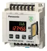
## **Simple and compact** KW1M-H **power meter perfect for control panels** Eco-POWER METER (SD card type)
## **FEATURES**
KW1M-H (SD card type)
- **In addition to simple measurement of voltage, current, power and integrated electrical power, etc., output of alarm signal is possible using the “alarm setting”.**
- **50 mm thickness**
- **Both screw and DIN rail installation (easy installation).**
- **Switchable between electrical power and electricity charge usage.**
- **Display of calculated CO2 value possible.**
- **Internal memory (Read by SD card)**
- **Built-in battery (for clock and log data backup)**
- **Addition of measurement items**
- **Power factor, frequency, and pulse counter**
- **Integrated electrical power by month/day/hour**
- **Calendar timer function**
## **Compliance with RoHS Directive** fF
## **PRODUCT TYPES**
## **Main unit**
|Product name|Phase and wire system|Operating<br>power supply|Measured voltage input|Terminal type|Model number|
|---|---|---|---|---|---|
||Single-phase two-wire system|||||
|KW1M-H Eco-POWER METER<br>SD card type|Single-phase three-wire system<br>Three-phase three-wire system|100 to 240 VAC,<br>50/60 Hz|100/200/400 VAC<br>(Select with setting mode)|Screw terminal<br>(M3 “+/−” screw)|AKW1121|
||Three-phase four-wire system|||||
## **Dedicated current transformer (CT)**
|Rated primary current|Model number|
|---|---|
|5A/50A (common)|AKW4801C|
|100A|AKW4802C|
|250A|AKW4803C|
|400A|AKW4804C|
Please order in accordance with the type of power distribution system you will be measuring. (Even if you will be using a secondary 5A CT, you will need an AKW4801C.)
## **Options**
|Product name|Descriptions|Model number|
|---|---|---|
|Mounting rail|Rail for holding DIN rail terminal socket|AT8-DLA1|
|Fastening plate|Plate for holding DIN rail|ATA4806|
|Backup battery|Used for memory backup function or clock function|AFPG804|
|Mounting frame|Used for mounting in a panel|AKW1822|
|**Tool and Software**|||
|Product name|Descriptions|Remark|
|KW Monitor*1|||
|(Data collection software|For parameter settings, editing of measurement values, and monitoring, etc.||
|for Eco-POWER METER)|||
|KW View (Power display tool)|For KW1M-H<br>You can then display the data as a graph by Eco-POWER METER data (electric power<br>only). (1 hour units fixed)|You can download from our website<br>(free of charge)*2|
|KW Watcher<br>(Electric power monitoring software)|Please use in situations where Web Datalogger Unit (DLU)/Data Logger Light (DLL) and<br>Eco-POWER METER are used together.<br>For easy “visualization” of data collected in DLU or DLL||
|Notes: *1. KW Monitor only uses MEWTOCOL. You cannot use MODBUS (RTU) type.|||
|*2. Customer registration is required to download data.|||
## **Other tool**
|Product name|Descriptions|Remark|
|---|---|---|
|KW1M-H Eco-POWER METER<br>User’s manual (pdf)|Detailed explanation of Eco-POWER METER usage|You can download from our website<br>(free of charge)*2|
All Rights Reserved © C OPYRIGHT Panasonic Electric Works Co., Ltd.
KW1M/KW1M-H Eco-POWER METER (AKW1)
## **MEASUREMENT ITEMS**
||Item|Unit|Data displayed range|
|---|---|---|---|
|Instantaneous electric power (Active)||kW|0.00 to 9999.99|
|Integrated electric power (Active)||kWh/MWh|0.00 to 9999.99kWh<br>0.00 to 9999999.99kWh (When 9-digit display)|
||R current|A|0.0 to 6000.0|
|Current|S current*1|A|0.0 to 6000.0|
||T current|A|0.0 to 6000.0|
||R (RS) voltage|V|0.0 to 9999.9|
|Voltage|S (RT) voltage*1|V|0.0 to 9999.9|
||T (TS) voltage|V|0.0 to 9999.9|
|Electricity charge*2||—|0.00 to 999999|
|Converted CO2value||kg-CO2|0.00 to 999999|
|Power factor*1||—|0.0 to 1.00 (Identify leading phase “–” or lagging phase) (Only in range of phase angleθ= –90°to +90°)|
|Frequency*1||Hz|47.5 to 63.0|
|Hour meter|ON time<br>OFF time|h (Hour)<br>h (Hour)|0.0 to 99999.9<br>0.0 to 99999.9|
|Pulse counter*1||—|0 to 999999|
*1. For AKW1110, AKW1121 only
*2. Eco-POWER METER is designed chiefly for managing energy saving. It is not intended to be used for billing.
## **SPECIFICATIONS**
## � **Main unit**
|Item||Specifcations|Specifcations|
|---|---|---|---|
|Rated operating voltage|100 to 240V AC|||
|Rated frequency|50/60Hz common|||
|Rated power consumption|AKW1110: 6 VA (240V AC at 25°C) / AKW1111, AKW1121: 8 VA (240V AC at 25°C)|||
|Allowable operating voltage range|85 to 264V AC (85% to 110% of rated operating voltage)|||
|Allowable momentary power-off time|10ms|||
|Ambient temperature|–10 to +50°C (–25°C to +70°C at storage)|||
|Ambient humidity|30 to 85%RH (at 20°C non-condensing)|||
||||• Outer edge (case) – all terminals|
|Breakdown voltage (initial)|Between the isolated circuits: 2000V for 1min||• Insulated circuit|
||||- Operating power supply terminals – Analog input terminals*1|
|Insulation resistance (initial)|Between the isolated circuits: 100MΩor more<br>(measured with 500V DC)||- Operating power supply terminals – Pulse input terminals*1<br>- RS485 – All other terminals<br>- Pulse output terminals – All other terminals|
|Vibration resistance|10 to 55Hz (1cycle/min) single amplitude: 0.375mm (1h on 3 axes)|||
|Shock resistance|Min. 294m/s2(5 times on 3 axes)|||
||LCD with backlight|||
|Display method|Upper section: Green, 4-digit, 16-segment, Letter height: 6.5 mm|||
||Lower section: Amber, 6-digit, 7-segment, Letter height:|7.5 mm||
|Power failure memory method|EEP-ROM (more than 100,000 overwrite)|||
|Size|75×90×50 mm|||
|Weight|AKW1110 and AKW1111: approx. 170g, AKW1121: approx. 180g (without battery)|||
- *1. Analog input terminals: No.3 to No.6 (for AKW1111), No.4 to No.6 (for AKW1110 and AKW1121) Pulse input terminals: No.12 and No.13 (for AKW1111)
No Connection terminal (N.C.) is internally connected to the analog input circuit.
All Rights Reserved © C OPYRIGHT Panasonic Electric Works Co., Ltd.
## KW1M/KW1M-H Eco-POWER METER (AKW1)
## � **Power input specifications**
||||Item|Specifcations<br>AKW1110<br>AKW1111 and AKW1121|
|---|---|---|---|---|
|Phase and|wire system|||Single-phase two-wire, Single-phase three-wire,<br>Three-phase three-wire (common)<br>Single-phase two-wire, Single-phase three-wire, Three-<br>phase three-wire, Three-phase four-wire (common)|
|||Rating||Single-phase two-wire: 0 to 220V AC (Line voltage)<br>Single-phase three-wire: 0 to 110V AC (Phase voltage)<br>Three-phase three-wire: 0 to 220V AC (Line voltage)<br>Single-phase two-wire: 0 to 440V AC (Line voltage)<br>Single-phase three-wire: 0 to 220V AC (Phase voltage)<br>Three-phase three-wire: 0 to 440V AC (Line voltage)<br>Three-phase four-wire: 0 to 254V AC (Phase voltage)|
|||||Up to 120% of rated input voltage|
|Input<br>voltage||Allowable measurement voltage||Single-phase two-wire: 0 to 264V AC (Line voltage)<br>Single-phase three-wire: 0 to 132V AC (Phase voltage)<br>Three-phase three-wire: 0 to 264V AC (Line voltage)<br>Single-phase two-wire: 0 to 528V AC (Line voltage)<br>Single-phase three-wire: 0 to 264V AC (Phase voltage)<br>Three-phase three-wire: 0 to 528V AC (Line voltage)<br>Three-phase four-wire: 0 to 300V AC (Phase voltage)|
|||||1.00 to 99.99 (Set with setting mode)|
|||VT ratio||*A Voltage transformer (VT) is required when measuring loads that exceed the rated input voltage (AKW1110 is<br>200 VAC and AKW1111 and AKW1121 are 440 VAC). (Please use a commercially available VT with rated|
|||||secondary measurement voltage of 110 V.)|
|||||<In case using dedicated CT>|
|||||5 A/50 A/100 A/250 A/400 A (Select with setting mode)|
|Input<br>current||Primary side rating||<In case using commercial CT with secondary side 5A><br>1 to 4000 A (Set with setting mode)|
|||||*Use a commercial CT with secondary side current of 5A when measure 400A or more.|
|||||*Accuracy coverage: 10 to 100% of rated current of CT|
|Special<br>functions||Cut-off current<br>Cut-off voltage||1.0 to 50.0%F.S. (Select with setting mode)<br>Within 5% of rated voltage (within voltage value sought by rated voltage×0.05×VT ratio) (fxed)|
|||Current threshold for hour meter||1.0 to 100.0%F.S.|
||||Instantaneous electric power||
||||Integrated electric power||
||||Voltage|±2.5% F.S. +1 digit (at 20°C, rated input, rated frequency, power factor 1)|
|Accuracy<br>(without<br>error in CT||Indication<br>accuracy|Current<br>Electricity charge<br>Calculated CO2value|*Accuracy coverage: 10 to 100% of rated current of CT|
|and VT)|||Hour meter|±0.01%+1digit (at 20°C), Monthly accuracy:±260 sec. (for your reference)<br>(In case power on start or current energizing:±0.01%+1s+1 digit, at 20°C)|
|||Temperature characteristics||±1.5% F.S. /10°C +1 digit (Range of –10 to 50°C for rated input, power factor 1)|
|||Frequency|characteristics|±1.5% F.S. +1 digit (Frequency change±5% based on rated frequency, for rated input, power factor 1)|
## � **Pulse input specifications (For AKW1111 and AKW1121)**
|||Item|Specifcations|
|---|---|---|---|
|Input mode|||Addition (Fixed)|
|Max. counting speed|||2kHz/30Hz (Select with setting mode)|
|Pulse input|||Min. input signal width: 0.25ms (When 2kHz selected)/16.7ms (When 30Hz selected), ON : OFF ratio = 1 : 1|
||||Contact/No contact (open collector)|
|Input signal (at 20°C)|||• Impedance when shorted: Max. 1kΩ<br>• Residual voltage when shorted: Max. 2V|
||||• Impedance when open: Min. 100kΩ|
|Output mode|||HOLD (Over count)|
|Pre-scale setting||Decimal point<br>Range|Setting possible up to 3 digits after decimal point<br>0.001 to 100.000 (Select with setting mode)|
## � **Pulse output (transistor output) specifications**
||Item|Specifcations|
|---|---|---|
|Number of output point||1 point|
|Insulation method||Optical coupler|
|Output type||Open collector|
|Output capacity||100mA 30V DC|
|Pulse width||Approx. 100ms|
|ON state voltage drop||1.5V or less|
|OFF state leakage current||100µA or less|
|Pulse output unit|AKW1110|0.001/0.01/0.1/1/10/100 kWh/Power alarm (AL-P)/Current alarm (AL-C)|
|(Select with setting<br>mode)|AKW1111 and AKW1121|0.001/0.01/0.1/1/10/100 kWh/Power alarm (AL-P)/Current alarm (AL-C)/Standby power alarm (AL-S)/<br>Counter (Cnt)|
* We recommend the setting of minimum unit for pulse output for measurement shown as below. Output pulse: 4 pulse or less per 1sec. Calculation method: (Pulse output unit: value of PL-P) > (Max. measured power [kW]) / (3600 [s] × 4 [pulse/s]) Note 1: Count errors may occur if pulse output unit is set so that 4 or more pulses are output per 1 second. Note 2: The connected counter or PLC may cause count errors if the OFF time of the pulse output unit is short.
All Rights Reserved © C OPYRIGHT Panasonic Electric Works Co., Ltd.
## KW1M/KW1M-H Eco-POWER METER (AKW1)
##
||Item|Specifcations|
|---|---|---|
|Interface||Conforming to RS485|
|Protocol||MEWTOCOL/MODBUS (RTU) (selectable with setting mode)|
|Isolation status||Isolated with the internal circuit|
|Number of connected units||99 (max.)*2, *3|
|Transmission distance||1200m*1|
|Transmission speed||38400/19200/9600/4800/2400 bps (selectable with setting mode)|
||Data length|8bit/7bit (selectable with setting mode)*4|
|Transmission format|Parity|Not available/Odd number/Even number (selectable with setting mode)|
||Stop bit|1 bit (fxed)|
|Communication method||Half-duplex|
|Synchronous system||Synchronous communication method|
|Ending resistance||Approx. 120Ω(built-in)|
- *1. Please check with the actual devices when some commercial devices with RS485 interface are connected. The number of connected devices, transmission distance, transmission speed may be different according to using transmission line.
- *2. For RS485 converter on the computer side, we recommend SI-35 and SI-35USB (from LINE EYE Co., Ltd.).
- *3. When using SI-35, SI-35USB or our PLC (which can be connected up to 99 units), up to 99 Eco-POWER METER can be connected. In case using this system with the other devices, up to 31 Eco-POWER METER can be connected.
- *4. With MODBUS (RTU) protocol, it works only with data length (8bit/7bit).
- Modbus Protocol is a communications protocol developed for PLCs by Modicon Inc.
*For RS485 communication and recommended cable, please refer to “PRECAUTIONS IN USING Eco-POWER METER”.
##
|Item||Specifcations|
|---|---|---|
||Save cycle|60 min. (on the hour) (fxed)|
|File type 1<br>(instantaneous value)*5|Save data|Instantaneous value: Integrated electric power, Instantaneous electric power, Current, Voltage, Power factor,<br>Frequency, Pulse count value|
||Save data amount|24 records per fle (max. approx. 1.5 years worth of data)|
|File type 2<br>(difference value)*5|Save cycle<br>Save data<br>Save data amount|60 min. (on the hour) (fxed)<br>Difference value: Integrated electric power, Pulse count value<br>24 records per fle (max. approx. 1.5 years worth of data)|
|||Select among1 min,5 min,10 min,15 min,30 min,or 60 min.|
|||Saved timing:|
|||When 1 min is selected: starts immediately after power is turned on|
||Save cycle|When 5 min is selected: 00, 05, 10, 15, 20, 25, 30... min after the hour|
|File type 3||When 10 min is selected: 00, 10, 20, 30, 40, 50 min after the hour|
|(instantaneous value detail)*5||When 15 min is selected: 00, 15, 30, 45 min after the hour|
|||When 60 min is selected: 00 min after the hour|
||Save data|Integrated electric power, Instantaneous electric power, Current, Voltage, Power factor, Frequency,<br>Pulse count value|
||Save data amount|Max. 7,200 records, Approx. 5 days (when save cycle is 1 min.)|
|Main unit display||Integrated electric power by month (latest data covering 1.5 year period)/Integrated electric power by day (latest<br>data covering 1 month period)/Integrated electric power by hour (latest data covering 24 hours period)|
|Calendar timer function||Time accuracy; monthly accuracy:±240 sec. (at –10°C)/monthly accuracy:±70 sec. (at 25°C)/<br>monthly accuracy:±240 sec. (at 50°C)|
|Content of battery backup/Battery life*6||Time measurement and log data retained/Approx. 2 years (at ambient temperature 25°C) (During discontinuity)|
- *5. In file types 1, 2, and 3, whether or not writing on SD card is conducted can be selected by each respective setting mode.
- *6. When the remaining battery level is low, the “BATT” display flashes. Replace the battery according to the battery replacement procedure. In addition, when the temperature of the main unit is high, the battery life decreases.
##
|Item||Specifcations|
|---|---|---|
|Support media|SD card*7||
|Supported format standards|Compliant with SD and SDHC standards*8||
- *7. Operation verified maker: Panasonic Corporation
- (SD/SDHC memory card: 2 GB, 4 GB, 8 GB)
- *8. To format SD cards, please download and use the formatting software available on the Panasonic website.
- [Panasonic website → Customer support → SD/SDHC card page → Software download list] http://panasonic.jp/support/sd_w/download The file system on a SD card that was formatted using standard PC software does not comply with the SD card standard.
All Rights Reserved © COPYRIGHT Panasonic Electric Works Co., Ltd.
KW1M/KW1M-H Eco-POWER METER (AKW1)
## **DIMENSIONS** (mm inch)
The CAD data of the products with a **CAD Data** mark can be downloaded from: http://panasonic-electric-works.net/ac
KW1M Standard type: AKW1110 and AKW1111 KW1M-H SD card type: AKW1121
Tolerance: ± 1.0 ± .039
Mounting hole dimensions (1:2)
**==> picture [492 x 275] intentionally omitted <==**
**----- Start of picture text -----**<br>
67 [±] [0.5]<br>2.638 [±] [.020]<br>• AKW1111/AKW1121<br>75 2-5 .197 dia.<br>2.95367 (Mounting hole)<br>2.638<br>39.1<br>1.539 1 [±] [0.5]<br>.039 [±] [.020]<br>Terminal cover<br>(transparent)<br>Connectors for current transformer (CT) .2366 1.1.043 [±] [0.5] [±] [.020]<br>18.2 11 11 1 [±] [0.5]<br>.717 .433 .433 .039 [±] [.020] 2 × M4 .157<br>67.8<br>2.669 1 [±] [0.5] 50<br>• AKW1110 SD card .039 [±] [.020] 1.969<br>M3 .118 (Fastening torque: 0.5 to 0.6 N·m) throttle* 47<br>1.850<br>25.1<br>.988<br>8<br>.315<br>39.1<br>1.539 AKW1110/1121 R1 .039<br>Terminal cover<br>(transparent)<br>Connectors for current<br>transformer (CT)<br>18.2 11 1 [±] [0.5]<br>.717 .433 .039 [±] [.020] AKW1111<br>67.8<br>2.669<br>*SD card throttle only applies to SD card type KW1M-H.<br>(54*)<br>(2.126*)<br>(55*) *When installing DIN rail<br>(2.165*)<br>820.5 ± 3.228.020 ±<br>90 82<br>3.543 3.228<br>71 2.795 60 2.362 58 2.283 35.4 1.394<br>**----- End of picture text -----**<br>
## **TERMINAL ARRANGEMENT AND WIRING DIAGRAMS**
## � **Terminal wiring**
Be sure to wire correctly according to the terminal arrangement and wiring diagrams. After completing wiring, be sure to attach the terminal cover for safety reasons.
**==> picture [319 x 139] intentionally omitted <==**
**----- Start of picture text -----**<br>
|||||||||
|---|---|---|---|---|---|---|---|
|�|Terminal arrangement|RS485|Pulse output|
|• AKW1110|IOP{}|E|qw|
|Function|Terminal No.|Function|
|Operating|L|Q|I|+|
|power supply|N|W|O|−|RS485|
|N.C.|E|P|E|
|P1|R|{|+|
|Measured|P0|T|}|−|Pulse output|
|voltage input|P2|Y|q|*|[1]|
|N.C.|U|*|[1]|w|*|[1]|N.C.|
|*1.|U|,|q|and|w|terminals are connected internal to analog input circuit.|QWERTYU|
|Please do not use for wiring with daisy chain.|P1|P0|P2|
|Operating|Measured|
|power supply|voltage input|
**----- End of picture text -----**<br>
**==> picture [409 x 140] intentionally omitted <==**
**----- Start of picture text -----**<br>
|||||||||||||||||
|---|---|---|---|---|---|---|---|---|---|---|---|---|---|---|---|
|RS485|Pulse output|Pulse input|
|E|
|• AKW1111|UIOP{}q|
|Function|Screw|Terminal No.|Screw|Function|
|Operating|L|Q|U|+|
|power supply|N|W|I|−|RS485|
|P1|M3.5|E|O|E|
|voltage inputMeasured|P0P2|“|+|/|−|” screw|RT|P{|“|+|/|−|” screwM3|+−|Pulse output|
|P3|Y|}|+|
|q|−|Pulse input|
|Q|W|E|R|T|Y|
|P1|P0|P2|P3|
|Operating|Measured|
|power supply|voltage input|
**----- End of picture text -----**<br>
All Rights Reserved © C OPYRIGHT Panasonic Electric Works Co., Ltd.
## KW1M/KW1M-H Eco-POWER METER (AKW1)
|**• AKW1121**<br>Function<br>Terminal No.<br>Function<br>Operating<br>power supply<br>L<br>Q<br>I<br>+<br>RS485<br>N<br>W<br>O<br>−<br>N.C.<br>E<br>P<br>E<br>Measured<br>voltage input<br>P1<br>R<br>{<br>+<br>Pulse output<br>P0<br>T<br>}<br>−<br>P2<br>Y<br>q<br>+<br>Pulse input<br>P3<br>U<br>w<br>−<br>IOP{<br>E<br>QWE<br>Operating<br>power supply<br>RS485<br>Puls|**• AKW1121**<br>Function<br>Terminal No.<br>Function<br>Operating<br>power supply<br>L<br>Q<br>I<br>+<br>RS485<br>N<br>W<br>O<br>−<br>N.C.<br>E<br>P<br>E<br>Measured<br>voltage input<br>P1<br>R<br>{<br>+<br>Pulse output<br>P0<br>T<br>}<br>−<br>P2<br>Y<br>q<br>+<br>Pulse input<br>P3<br>U<br>w<br>−<br>IOP{<br>E<br>QWE<br>Operating<br>power supply<br>RS485<br>Puls|**• AKW1121**<br>Function<br>Terminal No.<br>Function<br>Operating<br>power supply<br>L<br>Q<br>I<br>+<br>RS485<br>N<br>W<br>O<br>−<br>N.C.<br>E<br>P<br>E<br>Measured<br>voltage input<br>P1<br>R<br>{<br>+<br>Pulse output<br>P0<br>T<br>}<br>−<br>P2<br>Y<br>q<br>+<br>Pulse input<br>P3<br>U<br>w<br>−<br>IOP{<br>E<br>QWE<br>Operating<br>power supply<br>RS485<br>Puls|**• AKW1121**<br>Function<br>Terminal No.<br>Function<br>Operating<br>power supply<br>L<br>Q<br>I<br>+<br>RS485<br>N<br>W<br>O<br>−<br>N.C.<br>E<br>P<br>E<br>Measured<br>voltage input<br>P1<br>R<br>{<br>+<br>Pulse output<br>P0<br>T<br>}<br>−<br>P2<br>Y<br>q<br>+<br>Pulse input<br>P3<br>U<br>w<br>−<br>IOP{<br>E<br>QWE<br>Operating<br>power supply<br>RS485<br>Puls|**• AKW1121**<br>Function<br>Terminal No.<br>Function<br>Operating<br>power supply<br>L<br>Q<br>I<br>+<br>RS485<br>N<br>W<br>O<br>−<br>N.C.<br>E<br>P<br>E<br>Measured<br>voltage input<br>P1<br>R<br>{<br>+<br>Pulse output<br>P0<br>T<br>}<br>−<br>P2<br>Y<br>q<br>+<br>Pulse input<br>P3<br>U<br>w<br>−<br>IOP{<br>E<br>QWE<br>Operating<br>power supply<br>RS485<br>Puls|**• AKW1121**<br>Function<br>Terminal No.<br>Function<br>Operating<br>power supply<br>L<br>Q<br>I<br>+<br>RS485<br>N<br>W<br>O<br>−<br>N.C.<br>E<br>P<br>E<br>Measured<br>voltage input<br>P1<br>R<br>{<br>+<br>Pulse output<br>P0<br>T<br>}<br>−<br>P2<br>Y<br>q<br>+<br>Pulse input<br>P3<br>U<br>w<br>−<br>IOP{<br>E<br>QWE<br>Operating<br>power supply<br>RS485<br>Puls|
|---|---|---|---|---|---|
|Operating<br>power supply|L|<br>Q<br>W<br>E<br>R<br>T<br>Y<br>U|.<br>I|+<br>RS485<br>−<br>E||
||N|W|O|−||
|N.C.||E|P|E||
|Measured<br>voltage input|P1|R|{|+|Pulse output|
||P0|T|}|−||
||P2|Y|q|+|Pulse input|
||P3|U|w|−||
|||||||
## **The input voltage to each terminal is as follows. (AKW1111)**
|Terminal|Phase and wire system|Between terminals|Input voltage<br>AKW1111|
|---|---|---|---|
|Operating power supply|Single-phase two-wire|Q-W|100 to 240VAC (100-240V~) (Line voltage)|
||Single-phase two-wire|E-R|0 to 440VAC (0-440V~) (Line voltage)|
|Measured voltage input|Single-phase three-wire<br>Three-phase three-wire|E-R-T<br>E-R-T|0 to 220VAC (0-220V~: 3W) (Phase voltage)<br>0 to 440VAC (0-440V 3~) (Line voltage)|
||Three-phase four-wire|E-R-T-Y|0 to 254VAC (0-254V 3N~) (Phase voltage)|
## **The input voltage to each terminal is as follows. (AKW1110 and AKW1121)**
|Terminal|Phase and wire system|Between terminals|Input voltage<br>AKW1110<br>AKW1121|
|---|---|---|---|
|Operating power supply|Single-phase two-wire|Q-W|100 to 240VAC (100-240V~) (Line voltage)|
||Single-phase two-wire|R-T|0 to 220VAC (0-220V~) (Line voltage)<br>0 to 440VAC (0-440V~) (Line voltage)|
|Measured voltage input|Single-phase three-wire<br>Three-phase three-wire|R-T-Y<br>R-T-Y|0 to 110VAC (0-110V~: 3W) (Phase voltage)<br>0 to 220VAC (0-220V~: 3W) (Phase voltage)<br>0 to 220VAC (0-220V 3~) (Line voltage)<br>0 to 440VAC (0-440V 3~) (Line voltage)|
||Three-phase four-wire|R-T-Y-U|—<br>0 to 254VAC (0-254V 3N~) (Phase voltage)|
## � **Wiring diagrams**
## **• AKW1110 Measure load of 100 to 200VAC system**
- **Single-phase two-wire system**
- **Single-phase three-wire system/Three-phase three-wire system**
**==> picture [518 x 108] intentionally omitted <==**
**----- Start of picture text -----**<br>
*One CT is required. *Two CTs are required.<br>RS485 Pulse output RS485 Pulse output<br>+ – E + – + – E + –<br>8 9 10 11 12 13 14 8 9 10 11 12 13 14<br>*1 *1 *2 *2<br>30VDC0.1A CT1 30VDC0.1A CT1 CT2<br>1 2 3 4 5 6 7 1 2 3 4 5 6 7<br>N.C. *1 *1 N.C. *2<br> supplyPower side 12 Operating power supply100 to 240VAC50/60Hz *1 P1 P0Measured voltage input Direction of CTCT1K *Do not connect to CT2 and CT3.L Load side supplyPower side RNT RST 123 Operating power supply100 to 240VAC50/60Hz *2 P1 P0 P2Measured voltage input CT1CT2 *Do not connect to CT3.Load side<br>K L<br>Direction of CT<br>**----- End of picture text -----**<br>
- *1. Do not wire to E , Y , U , q , w terminal. They are connected internal.
- *2. Do not wire to E , U , q , w terminal. They are connected internal.
## **When measuring a load with exceed rated input voltage**
The voltage transformer (VT) is required when you measure a load with exceed rated input voltage (220 V AC system). Use commercial VT, those secondary rating is 110 V.
- **Single-phase two-wire system**
- **Single-phase three-wire system/**
## **Three-phase three-wire system**
**==> picture [310 x 59] intentionally omitted <==**
**----- Start of picture text -----**<br>
Eco-POWER METER (Secondary side) Eco-POWER METER (Secondary side)<br>R T R T Y<br>VT VT<br>Power 1 (Primary side) Power 1 R R (Primary side)<br> supply side 2 Load side supply side 23 NT ST Load side<br>**----- End of picture text -----**<br>
- *Grounding the secondary side of voltage transformer (VT) and current transformer (CT) is not necessary with low voltage circuit.
All Rights Reserved © C OPYRIGHT Panasonic Electric Works Co., Ltd.
KW1M/KW1M-H Eco-POWER METER (AKW1)
## **• AKW1111**
## **Measure load of 100 to 200 VAC and 400 VAC system**
**==> picture [522 x 237] intentionally omitted <==**
**----- Start of picture text -----**<br>
• Single-phase two-wire system • Single-phase three-wire system/Three-phase three-wire system<br>*One CT is required. *Two CTs are required.<br>RS485 Pulse output Pulse input RS485 Pulse output Pulse input<br>+ – E + – + – + – E + – + –<br>7 8 9 10 11 12 13 7 8 9 10 11 12 13<br>30VDC0.1A CT1 30VDC0.1A CT1 CT2<br>1 2 3 4 5 6 1 2 3 4 5 6<br>*1 *1 *2<br>P1 P0 *Do not connect to CT2 and CT3. P1 P0 P2 *Do not connect to CT3.<br> supplyPower side 12 Operating power supply100 to 240VAC50/60Hz Measured voltage input CT1K L Load side supplyPower side RNT RST 123 Operating power supply100 to 240VAC50/60Hz Measured voltage input CT1CT2 Load side<br>Direction of CT K L<br>• Three-phase four-wire system Direction of CT<br>*Three CTs are required.+ RS485– E Pulse output+ – Pulse input+ – *1. Do not wire to *2. Do not wire to TY , terminal. They are connected internal. Y terminal. They are connected internal.<br>7 8 9 10 11 12 13<br>30VDC0.1A CT1 CT2 CT3<br>1 2 3 4 5 6<br>P1 P0 P2 P3<br>R 1 Operating power supply100 to 240VAC50/60Hz Measured voltage input CT1<br>Power S 2 CT2<br> supply side T 3 CT3 Load side<br>N 4<br>K L<br>Direction of CT<br>**----- End of picture text -----**<br>
## **When measuring a load with exceed rated input voltage**
The voltage transformer (VT) is required when you measure a load with exceed rated input voltage (440 V AC system). Use commercial VT, those secondary rating is 110 V.
**==> picture [482 x 84] intentionally omitted <==**
**----- Start of picture text -----**<br>
• Single-phase two-wire system • Single-phase three-wire system/ • Three-phase four-wire system<br>Three-phase three-wire system<br>Eco-POWER METER (Secondary side) Eco-POWER METER (Secondary side) Eco-POWER METER (Secondary side)<br>E R E R T E R T Y<br>VT VT VT<br> supplyPower side 12 (Primary side)Load side supplyPower side 123 RNT RST (Primary side)Load side supplyPower RST (Primary side)Load side<br> side N<br>**----- End of picture text -----**<br>
*Grounding the secondary side of voltage transformer (VT) and current transformer (CT) is not necessary with low voltage circuit.
## **• AKW1121**
**Measure load of 100 to 200 VAC and 400 VAC system**
**==> picture [524 x 237] intentionally omitted <==**
**----- Start of picture text -----**<br>
• Single-phase two-wire system • Single-phase three-wire system/Three-phase three-wire system<br>*One CT is required. *Two CTs are required.<br>RS485 Pulse output Pulse input RS485 Pulse output Pulse input<br>+ – E + – + – + – E + – + –<br>8 9 10 11 12 13 14 8 9 10 11 12 13 14<br>30VDC0.1A CT1 30VDC0.1A CT1 CT2<br>1 2 3 4 5 6 7 1 2 3 4 5 6 7<br>N.C. *1 *1 N.C. *2<br> supplyPower side 12 Operating power supply100 to 240VAC50/60Hz P1 P0Measured voltage input Direction of CTCT1K *Do not connect to CT2 and CT3.L Load side supplyPower side RNT RST 123 Operating power supply100 to 240VAC50/60Hz P1 P0 P2Measured voltage input CT1CT2 *Do not connect to CT3.Load side<br>K L<br>• Three-phase four-wire system Direction of CT<br>*Three CTs are required.+ RS485– E Pulse output+ – Pulse input+ – *1. Do not wire to *2. Do not wire to YU , terminal. They are connected internal. U terminal. They are connected internal.<br>8 9 10 11 12 13 14<br>30VDC0.1A CT1 CT2 CT3<br>1 2 3 4 5 6 7<br>N.C.<br>P1 P0 P2 P3<br>R 1 Operating power supply100 to 240VAC50/60Hz Measured voltage input CT1<br>Power S 2 CT2<br> supply side T 3 CT3 Load side<br>N 4<br>K L<br>Direction of CT<br>**----- End of picture text -----**<br>
All Rights Reserved © C OPYRIGHT Panasonic Electric Works Co., Ltd.
KW1M/KW1M-H Eco-POWER METER (AKW1)
## **When measuring a load with exceed rated input voltage**
The voltage transformer (VT) is required when you measure a load with exceed rated input voltage (440 V AC system). Use commercial VT, those secondary rating is 110 V.
## **• Single-phase two-wire system**
**==> picture [480 x 84] intentionally omitted <==**
**----- Start of picture text -----**<br>
• Single-phase two-wire system • Single-phase three-wire system/ • Three-phase four-wire system<br>Three-phase three-wire system<br>Eco-POWER METER (Secondary side) Eco-POWER METER (Secondary side) Eco-POWER METER (Secondary side)<br>R T R T Y R T Y U<br>VT VT VT<br> supplyPower side 12 (Primary side)Load side supplyPower side 123 RNT RST (Primary side)Load side supplyPower RST (Primary side)Load side<br> side N<br>**----- End of picture text -----**<br>
*Grounding the secondary side of voltage transformer (VT) and current transformer (CT) is not necessary with low voltage circuit.
## � **Caution for Wiring**
## **• M3 screw: AKW1110 and AKW1121**
(1) Terminal fastening torque should be 0.5 to 0.6N·m. In case of using a crimping terminal, use it with insulating sleeve applicable to M3 screw. (Refer to the below.)
## **• M3.5 screw: AKW1111**
(1) Terminal fastening torque should be approx. 1.0 N·m. In case of using a crimping terminal, with insulating sleeve applicable to M3.5 screw. (Refer to the below.)
**==> picture [480 x 43] intentionally omitted <==**
**----- Start of picture text -----**<br>
5.8mm or less 3.2mm dia. 5.8mm or less 3.2mm 6.6mm or less 3.7mm dia. 6.6mm or less 3.7mm<br>**----- End of picture text -----**<br>
(2) To protect the device, it is necessary to install power switch and circuit breaker in operating power supply circuit. And this has no built-in power switch, circuit breaker or fuse for measured voltage input parts. Therefore it is necessary to install them in the circuit near main unit.
(3) We recommend a wire with the cross section of 0.75 to 1.25 mm2 for operating power supply line and measured voltage input line. (4) Use fire resistant electrical wire (UL electrical wire, etc.)
## **CAUTIONS FOR SAFETY**
## **Please use correctly only after you have thoroughly read “User’s Manual, Instruction Manual, and Catalog”.**
All Rights Reserved © C OPYRIGHT Panasonic Electric Works Co., Ltd.
Updated at June 9, 2026
Panasonic Industry is a global leader in the design and manufacture of high-quality electronic components. Renowned for a commitment to continuous innovation, the company provides the essential building blocks that empower modern engineering. From industrial automation to consumer electronics, Panasonic's components are trusted worldwide for their outstanding reliability, efficiency, and long-term performance. The extensive portfolio is anchored by a massive selection of passive components, featuring an industry-leading range of aluminium electrolytic, film, and polymer capacitors. Alongside these advanced capacitance solutions, engineers rely on Panasonic's robust power inductors and a highly versatile array of electromechanical devices, including solid-state, power, and signal relays engineered to excel in demanding environments. Beyond core passives and switching solutions, the offering encompasses critical circuit protection devices such as TVS varistors and NTC thermistors, as well as sophisticated thermal management materials. Panasonic also delivers precision light and motion sensors, highly reliable batteries, and advanced Bluetooth and WLAN connectivity modules, providing a comprehensive ecosystem of components to support next-generation technological design.
About Novapart
Novapart is a B2B electronic component broker specialising in stock shortages and cost reduction. We source hard-to-find parts and identify compliant alternatives across a catalogue of 540,000+ components from 500+ manufacturers.
Learn more →Stock Shortage Specialist
When a component is unavailable, discontinued or has an unacceptable lead time, we tap into our network of vetted European and Asian distributors to source what you need — without compromising on quality or traceability.
Request a quote →Compliant Alternatives
We identify pin-to-pin, electrically equivalent substitutes that meet the same certifications (RoHS, AEC-Q100, REACH) as your original specification — validated against datasheets, not just part numbers. Often at a lower cost.
BOM Analysis service →