
Image not available
Illustrative purposes only

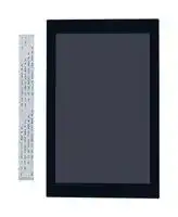
AES-ACC-DISP-7INCH
TFT LCD, 7 ", 800 x 1280 Pixels, Portrait, 3.3V
⚠️ Reference pricing provided. In case of supply shortages, we will connect you with our trusted procurement partners to ensure your project's continuity.
- Manufacturer: AVNET
- Product type: TFT LCD Displays
- SVHC: No SVHC (25-Jun-2025)
- VGA Size: -
- Resolution: 800 x 1280 Pixels
- Module Size: 180.92mm x 113.94mm
- Touchscreen: Projected Capacitive Touch
- Display Size: 7"
- Logic Voltage: 3.3V
- Product Range: -
- Display Pinout: 40 Way Connector
- Interface Type: MIPI, I2C
- Display Appearance: -
- Display Brightness: 340cd/m²
- Display Orientation: Portrait
- Operating Temperature Max: 70°C
- Operating Temperature Min: -20°C
| Delivery and price | |
|---|---|
| Units per pack | 1 |
| Price | 211.71 € |
| Current stock | 25+ |
| Lead time | 30 days |
Datasheet

## fe
## **Specifications for LCD module**
|**Customer**|**Avnet**|
|---|---|
|**Customer part no.**|**AES-ACC-DISP-7INCH**|
|**Ampire part no.**|**AM-8001280GTZQW-T10H**|
|**Approved by**||
|**Date**||
## **Preliminary Specification**
## **Formal Specification**
**AMPIRE CO., LTD. 4F., No.116, Sec. 1, Xintai 5th Rd., Xizhi Dist., New Taipei City221, Taiwan (R.O.C.)** 新北市汐止區新台五路一段 **116** 號 **4** 樓 **(** 東方科學園區 **A** 棟 **) TEL:886-2-26967269 , FAX:886-2-26967196 or 26967270**
|Approved by|Checked by|Organized by|
|---|---|---|
|Kokai|Mark|Lawlite|
This Specification is subject to change without notice.
Date: 2024/10/07 AMPIRE CO., LTD. 1
## **RECORD OF REVISION**
|||**RECORD OF REVISION**||
|---|---|---|---|
|Revision Date|Page|Contents|Editor|
|2023/10/23<br>2024/01/08<br>2024/03/19<br>2024/10/07|--<br>27<br>27|New Release<br>TFT-8001280-09-A rename to<br>AM-8001280GTZQW-T10H<br>Update PCB drawing<br>Update PCB drawing|Mantle<br>Lawlite<br>Lawlite<br>Lawlite|
Date: 2024/10/07 AMPIRE CO., LTD. 2
## **1. General Descriptions**
7 inch Amorphous-TFT-LCD (Thin Film Transistor Liquid Crystal Display) module. This module is composed of a 7” TFT-LCD panel and backlight unit.
## **1.1 Features**
- 7 inch configuration
- 4wire mipi interface
- Driver IC : ILI9881C
- RoHS
- Projective Capacitive Touch
- Touch Controller : ILI2132
- Interface : I2C
- Cover Lens : 113.94*180.92*1.1Tmm. Black frame.
- Optical bonding between LCD and touch panel.
- Clear display
- Glare Reduction
- No Condensation
## **1.2 Customize**
- (1) Bridge board
- (2) FFC
Date: 2024/10/07 AMPIRE CO., LTD. 3
## **1.3 Product Summary**
|**Item**|**Specification**|**Remark**|
|---|---|---|
|LCD Size|7.0 inch (Diagonal)||
|Resolution|800 x 3 (RGB) x 1280||
|Display Mode|Normally Black.||
|Pixel pitch|0.03925 (W) x 0.11775(H) mm||
|Active area|94.2(W) x 150.72(H) mm||
|Interface|MIPI||
|Color arrangement|RGB-stripe||
|Luminance|340|cd/m2|
|Viewing Direction|All direction||
|Pixel Density|216 PPI||
|Color Depth|24 bits||
Date: 2024/10/07 AMPIRE CO., LTD. 4
## **2. Absolute Maximum Ratings**
|**Item**|**Symbol**|**Min.**|**Max.**|**Unit**|**Remark**|
|---|---|---|---|---|---|
|Power Supply Voltage|3V3|-0.3|+3.6|V|-|
|IO Supply voltage|1V8|-0.3|+3.6|V||
|Operating Temperature|TOP|-20|70|`℃`|Note 1|
|Storage Temperature|TST|-30|80|`℃`|Note 1|
- Note(1) The maximum rating is defined as above based on the chamber temperature, which might be different from ambient temperature after assembling the panel into the application. Moreover, some temperature-related phenomenon as below needed to be noticed:
- Background color, contrast and response time would be different in temperatures other than 25 ℃ .
- Operating under high temperature will decrease LED lifetime.
Date: 2024/10/07 AMPIRE CO., LTD. 5
## **3. Electrical Characteristics**
## **3.1 LCD Characteristics**
|**Item**<br>~~ee~~<br>~~ee~~|**Symbol**<br>~~ee~~<br>~~ee~~|**Min.**<br>~~ee~~<br>~~ee~~|**Typ.**<br>~~ee~~<br>~~es~~|**Max.**<br>~~ee~~<br>~~ee~~|**Unit**<br>~~es~~<br>~~es~~|**Note**|
|---|---|---|---|---|---|---|
|Power Supply Voltage<br>~~ee ~~<br>~~ee~~<br>~~ee~~|3V3<br> ~~ee~~<br>~~ee~~<br>~~ee~~|3.2<br>~~ee~~<br>~~ee~~<br>~~ee~~|3.3<br>~~ee~~<br>~~es~~<br>~~ee~~|3.4<br>~~ee~~<br>~~ee~~<br>~~ee~~|V<br>~~es~~<br>~~es~~||
|IO Supply voltage<br>~~ee~~<br>~~ee~~<br>~~ee~~|1V8<br>~~ee~~<br>~~ee~~<br>~~ee~~|1.74<br>~~ee~~<br>~~ee~~<br>~~ee~~|1.8<br>~~es~~<br>~~ee~~<br>~~es~~|3.4<br>~~ee ~~<br>~~ee~~<br>~~ee~~|V<br> ~~es~~||
|Input Hi Logic Voltage<br>~~ee~~<br>~~ee~~<br>~~ee~~|VIH<br>~~ee~~<br>~~ee~~<br>~~ee~~|0.7*1V8<br>~~ee~~<br>~~ee~~<br>~~ee~~|--<br>~~ee~~<br>~~es~~<br>~~ee~~|1V8<br>~~ee~~<br>~~ee~~<br>~~ee~~|V<br>~~ee~~|LCD_RESET|
|Input Low Logic<br>Voltage<br>~~ee~~<br>~~ee~~<br>~~ee~~|VIL<br>~~ee~~<br>~~ee~~<br>~~ee~~|-0.3<br>~~ee~~<br>~~ee~~<br>~~ee~~|--<br>~~es~~<br>~~ee~~<br>~~ee~~|0.3*1V8<br>~~ee~~<br>~~ee~~<br>~~es~~|V<br>~~ee~~<br>~~ee~~|LCD_RESET|
|Out Hi Logic Voltage<br>~~ee~~<br>~~ee~~<br>~~a~~|VOH<br>~~ee ~~<br>~~ee~~<br>~~ee~~|0.8*1V8<br> ~~ee ~~<br>~~ee~~<br>~~ee~~|--<br> ~~ee~~<br>~~ee~~<br>~~ee~~|1V8<br>~~ee ~~<br>~~es~~<br>~~ee~~|V<br> ~~ee~~<br>~~ee~~<br>~~ee~~|LCD_TE|
|Out Low Logic<br>Voltage<br>~~ee~~<br>~~a~~|VOL<br>~~ee~~<br>~~ee~~|-0.3<br>~~ee ~~<br>~~ee~~|--<br> ~~ee~~<br>~~ee~~|0.2*1V8<br>~~es ~~<br>~~ee~~|V<br> ~~ee~~<br>~~ee~~|LCD_TE|
## **3.2 Backlight Characteristics**
|**Item**|**Symbol**|**Min.**|**Typ.**|**Max.**|**Unit**|**Note**|
|---|---|---|---|---|---|---|
|LED Forward Current|IF|--|80|--|mA|Ta=25℃|
|LED Forward Voltage|VF|--|15|18|V|IF=80mA,<br>Ta=25℃|
|LED life time||30,000|50,000|-|Hr|IF=80mA,<br>Ta=25℃|
- The constant current source is needed for white LED back-light driving.
- Operating life means brightness goes down to 50% minimum brightness. LED life time is estimated data. Ta=25℃
- When LCM is operated over 40 ℃ ambient temperature, the IF should be follow :
Date: 2024/10/07 AMPIRE CO., LTD. 6
**==> picture [313 x 197] intentionally omitted <==**
**----- Start of picture text -----**<br>
80<br>60<br>40<br>20<br>-30 -20 -10 0 10 20 30 40 50 60 70<br>Ambient Temperature Ta ( ℃ )<br>Allowable Forward Current IF (mA)<br>**----- End of picture text -----**<br>
Date: 2024/10/07 AMPIRE CO., LTD. 7
## **3.4 Touch Panel Unit**
## **3.4.1 Basic Characteristics**
|**ITEM**|**SPECIFICATION **|
|---|---|
|**Type **|Projective Capacitive Touch Panel|
|**Activation**|Two-fingers or Single-finger|
|**X/Y Position Reporting**|AbsolutePosition|
|**Touch Force**|No contact pressurerequired|
|**Calibration**|No need for calibration|
|**Report Rate**|Approx 100points/sec|
|**Interface**|**I2C**|
|**Control IC**|**ILI2132 **|
## **3.4.2 Electronic Characteristics**
Specify the normal operating condition
(GND=0V)
|**Item**|**Symbol**|**Min.**|**Typ.**|**Max.**|**Unit**|**Note**|
|---|---|---|---|---|---|---|
|Power Supply Voltage|VDD|3.0|3.3|3.6|V||
|Low Level Input Voltage|VIL|0|--|0.8|V|1|
|High Level Input Voltage|VIH|0.8*VDD|--|VDD|V|1|
|Power Consumption|IVCC||T.B.D||mA||
Note 1: TOUCH_SDA , TOUCH_SCL, TOUCH_RESET
## **3.4.3 Grounding**
TP needs to work in environment with stable stray capacitance. In order to minimize the variation in stray capacitance, all conductive mechanical parts must not be floating. Intermittent floating any conductive part around the touch sensor may cause significant stray capacitance change and abnormal touch function. It is recommended to keep all conductive parts having same electrical potential as the GND of the touch controller module.
GND1, GND2 and GND3 should be connected together to have the same ground
Date: 2024/10/07 AMPIRE CO., LTD. 8
## **4. AC Characteristics**
## **DSI layer definitions**
Date: 2024/10/07 AMPIRE CO., LTD. 9
Date: 2024/10/07 AMPIRE CO., LTD. 10
Date: 2024/10/07 AMPIRE CO., LTD. 11
Date: 2024/10/07 AMPIRE CO., LTD. 12
Date: 2024/10/07 AMPIRE CO., LTD. 13
## **4.4 Interface Timings**
Date: 2024/10/07 AMPIRE CO., LTD. 14
## **4.5 Power ON/OFF Sequence**
Date: 2024/10/07 AMPIRE CO., LTD. 15
## **5. Timing**
||||||||
|---|---|---|---|---|---|---|
||||**Values**||||
|**Item**|**Symbol**||||**Unit**|**Remark**|
||||||||
|||**Min.**|**Typ.**|**Max.**|||
||||||||
|Clock Frequency|fclk|40.8|51.2|67.2|MHz|Frame rate<br>=60Hz|
|Horizontal display area|thd||800||DCLK||
|Horizontal Back Porch|HBP||20||DCLK||
|Horizontal Pulse Width|HS||20||DCLK||
|Horizontal Front Porch|HFP||32||DCLK||
|HS Blanking|thb||72||DCLK||
|HS period time|th||872||DCLK||
|Vertical display area|tvd||1280||H||
|Vertical Back Porch|VBP||6||H||
|Vertical Pulse Width|VS||4||H||
|Vertical Front Porch|HFP||8||H||
|VS Blanking|thb||18||H||
|VS period time|tv||1298||H||
Date: 2024/10/07 AMPIRE CO., LTD. 16
## **6. Interface**
||||**Description**||
|---|---|---|---|---|
|**Pin No.**|<br>**Symbol**|**I/O**||**Note**|
||||||
|1|GND|P|Power Ground||
|2|NC|-|No connection||
|3|LED_A|P|Power for LED backlight anode||
|4|LED_A|P|Power for LED backlight anode||
|5|NC|-|No connection||
|6|LED_K|P|Power for LED backlight negative||
|7|LED_K|P|Power for LED backlight negative||
|8|GND|P|Power Ground||
|9|GND|P|Power Ground||
|10|3V3|P|Power Supply voltage Analog||
|11|3V3|P|Power Supply voltage Analog||
|12|GND|P|Power Ground||
|13|D3P|I|MIPI DSI differential data pair||
|14|D3N|I|MIPI DSI differential data pair||
|15|GND|P|Power Ground||
|16|D2P|I|MIPI DSI differential data pair||
|17|D2N|I|MIPI DSI differential data pair||
|18|GND|P|Power Ground||
|19|D1P|I|MIPI DSI differential data pair||
|20|D1N|I|MIPI DSI differential data pair||
|21|GND|P|Power Ground||
|22|CLKP|I|MIPI DSI differential CLK pair||
|23|CLKN|I|MIPI DSI differential CLK pair||
|24|GND|P|Power Ground||
|25|D0P|I|MIPI DSI differential data pair||
|26|D0N|I|MIPI DSI differential data pair||
|27|GND|P|Power Ground||
Date: 2024/10/07 AMPIRE CO., LTD. 17
|28|1V8|P|Power Supply voltage Digital||
|---|---|---|---|---|
|29|1V8|P|Power Supply voltage Digital||
|30|1V8|P|Power Supply voltage Digital||
|31|LCD_TE|O|Tearing effect output pin.<br>Leave the pin open when not in use.||
|32|LCD_RESET|I|LCD reset signal, low active||
|33|GND|P|Power Ground||
|34|TOUCH_RESET|<br>I|Touch reset signal, low active||
|35|TOUCH_SCL|I|Touch IC I2C Bus serial clock||
|36|TOUCH_SDA|I/O|Touch IC I2C Bus serial data||
|37|TOUCH_VDD|P|Power Supply voltage touch IC||
|38|TOUCH_VDD|P|Power Supply voltage touch IC||
|39|TOUCH_INT#|O|Touch IC interrupt. Active Low.||
|40|GND|P|Power Ground||
Note (1): Be sure to apply the power voltage as the power sequence spec.
Date: 2024/10/07 AMPIRE CO., LTD. 18
## **7. Optical Specifications**
## **7.1 TFT Optical Characteristics**
|**Item**|**Item**|**Symbol**|**Condition**|**Min.**|**Typ. **|**Max.**|**Unit**|**Remark**|
|---|---|---|---|---|---|---|---|---|
|View Angles||θT|CR`≧`10|70|85|-|Degree|<br>Note(2)|
|||θB||70|85|-|||
|||θL||70|85|-|||
|||θR||70|85|-|||
|Contrast Ratio||CR|θ=0°|(700)|(1000)|<br>-||Left/right 0°<br>Top/bottom 5°|
|Response Time||TON+TOFF|25`℃`|-|25|35|ms|Note(1)(4)|
|Chromaticity|White|x||-0.05|(0.313)|+0.05||Note(1)(5)|
|||y|||(0.329)||||
||Red|x|||T.B.D||||
|||y|||T.B.D||||
||Green|x|||T.B.D||||
|||y|||T.B.D||||
||Blue|x|||T.B.D||||
|||y|||T.B.D||||
|Uniformity||U||75|80|-|%|Note(1)(6)|
|NTSC|||CIE1931|45|50|-|%||
|Luminance||L||300|340|-|cd/m2|Note(7)|
Test Conditions:
1. IF= 80mA, the ambient temperature is 25 `℃` .
2. The test systems refer to Note ( 1 ) and Note ( 2 ) .
## Definition of optical measurement system
The optical characteristics should be measured in dark room. After 10 Minutes operation, the optical properties are measured at the center point of the LCD screen. All input terminals LCD panel must be ground when measuring the center area of the panel.
Date: 2024/10/07 AMPIRE CO., LTD. 19
## Note(1) Definition of optical measurement system
The optical characteristics should be measured in dark room. After 30 minutes operation, the optical properties are measured at the center point of the LCD screen. (Response time is measured by Photo detector TOPCON BM-7, other items are measured by BM-7/Field of view: 1° / Height: 500mm.)
Note(2) Definition of viewing angle range
## Note(3) Definition of Response time
The response time is defined as the LCD optical switching time interval between “White” state and “Black” state. Rise time (TON) is the time between photo detector output intensity changed from 90% to 10%. And fall time (T OFF) is the time between photo detector output intensity changed from 10% to 90%.
Date: 2024/10/07 AMPIRE CO., LTD. 20
Note(4) Definition of contrast ratio
Luminance measured when LCD on the “White” state Contrast ratio (CR) =
Luminance measured when LCD on the “Black” state
- Note(5) Definition of color chromaticity (CIE1931)
- Color coordinated measured at center point of LCD.
- Note(6) All input terminals LCD panel must be ground when measuring the center area of the panel.
- Note(7) Definition of Luminance Uniformity
- Active area is divided into 9 measuring areas (Refer to bellow figure). Every measuring point is placed at the center of each measuring area.
- Bmin
Luminance Uniformity (Yu) =
Bmax
L ----- Active area length W ----- Active area width
Bmax: The measured maximum luminance of all measurement position. Bmin: The measured minimum luminance of all measurement position.
Date: 2024/10/07 AMPIRE CO., LTD. 21
## **8. Reliability Test Items**
|**Test Item**|**Test Conditions**|**Note**|
|---|---|---|
|High Temperature Operation|703C , t=240 hrs||
|Low Temperature Operation|-203C , t=240 hrs||
|High Temperature Storage|803C , t=240 hrs|1,2|
|Low Temperature Storage|-303C , t=240 hrs|1,2|
|Storage at High Temperature<br>and Humidity|60C, 90% RH , 240 hrs|1,2|
|Thermal Shock Test|-20C (30min) ~ 70C (30min)<br>100 cycles|1,2|
|Vibration Test (Packing)|Sweep frequency : 10 ~ 55 ~ 10 Hz/1min<br>Amplitude : 0.75mm<br>Test direction : X.Y.Z/3 axis<br>Duration : 30min/each axis|2|
- Note(1) Condensation of water is not permitted on the module.
- Note(2) The module should be inspected after 1 hour storage in normal conditions (15-35°C, 45-65%RH).
- Note(3) The module shouldn’t be tested over one condition, and all the tests are independent.
- Note(4) All reliability tests should be done without the protective film.
Definitions of life end point:
- Current drain should be smaller than the specific value.
- Function of the module should be maintained.
- Appearance and display quality should not have degraded noticeably.
- Contrast ratio should be greater than 50% of the initial value.
Date: 2024/10/07 AMPIRE CO., LTD. 22
## **9. General Precaution**
## **9.1 Disassembling or Modification**
- (1) Do not disassemble or modify the module. It may damage sensitive parts inside LCD module, and may cause scratches or dust on the display. AMPIRE does not warrant the module, if customers disassemble or modify the module.
## **9.2 Breakage of LCD Panel**
- (1) If LCD panel is broken and liquid crystal spills out, do not ingest or inhale liquid crystal, and do not contact liquid crystal with skin.
- (2) If liquid crystal contacts mouth or eyes, rinse out with water immediately.
- (3) If liquid crystal contacts skin or cloths, wash it off immediately with alcohol and rinse thoroughly with water.
- (4) Handle carefully with chips of glass that may cause injury, when the glass is broken.
## **9.3 Electric Shock**
- (1) Disconnect power supply before handling LCD module.
- (2) Do not pull or fold the LED cable.
- (3) Do not touch the parts inside LCD modules and the fluorescent LED’s connector or cables in order to prevent electric shock.
## **9.4 Absolute Maximum Ratings and Power Protection Circuit**
- (1) Do not exceed the absolute maximum rating values, such as the supply voltage variation, input voltage variation, variation in parts’ parameters, environmental temperature, etc., otherwise LCD module may be damaged.
- (2) Please do not leave LCD module in the environment of high humidity and high temperature for a long time.
- (3) It’s recommended to employ protection circuit for power supply.
## **9.5 Operation**
- (1) Do not touch, push or rub the polarizer with anything harder than HB pencil lead.
- (2) Use fingerstalls of soft gloves in order to keep clean display quality, when persons handle the LCD module for incoming inspection or assembly.
- (3) When the surface is dusty, please wipe gently with absorbent cotton or other soft material.
- (4) Wipe off saliva or water drops as soon as possible. If saliva or water drops contact with polarizer for a long time, they may cause deformation or color fading.
Date: 2024/10/07 AMPIRE CO., LTD. 23
- (5) When cleaning the adhesives, please use absorbent cotton wetted with a little petroleum benzene or other adequate solvent.
## **9.6 Mechanism**
- (1) Please mount LCD module by using mounting holes arranged in four corners tightly.
## **9.7 Static Electricity**
- (1) Protection film must remove very slowly from the surface of LCD module to prevent from electrostatic occurrence.
- (2) Because LCD modules use CMOS-IC on circuit board and TFT-LCD panel, it is very weak to electrostatic discharge. Please be careful with electrostatic discharge. Persons who handle the module should be grounded through adequate methods.
## **9.8 Strong Light Exposure**
- (1) The module shall not be exposed under strong light such as direct sunlight. Otherwise, display characteristics may be changed.
## **9.9 Disposal**
- (1) When disposing LCD module, obey the local environmental regulations.
## **9.10 Others**
- (1) AMIPRE will provide one year warrantee for all products, and three months warrantee for all repairing products.
- (2) Do not keep the LCD at the same display pattern continually. The residual image will happen and it will damage the LCD. Please use screen saver.
Date: 2024/10/07 AMPIRE CO., LTD. 24
## **10. Outline Dimension**
Date: 2024/10/07 AMPIRE CO., LTD. 25
Date: 2024/10/07 AMPIRE CO., LTD. 26
## **11. Bridge Board**
## **PCB Outline: 87*56 mm , 4L**
Date: 2024/10/07 AMPIRE CO., LTD. 27
## **Interface**
(1). CN1: Connector to LCM FPC (MIPI interface) (2). CN2: CSF-2481-301R/P0.5 30PIN or equivalent. (4-lane MIPI)
|Pin|Signal name|Description|
|---|---|---|
|1|GND|Ground|
|2|DSI_DP3|MIPI DSItransmit differentialsignal3 pairpositive|
|3|DSI_DN3|MIPI DSI transmit differential signal 3 pair negative|
|4|GND|Ground|
|5|DSI_DP2|MIPI DSI transmit differential signal 2pairpositive|
|6|DSI_DN2|MIPI DSItransmit differentialsignal 2pair negative|
|7|GND|Ground|
|8|DSI_DP1|MIPI DSI transmit differential signal 1pairpositive|
|9|DSI_DN1|MIPI DSItransmit differentialsignal 1pair negative|
|10|GND|Ground|
|11|DSI_DP0|MIPI DSI transmit differential signal 0pairpositive|
|12|DSI_DN0|MIPI DSI transmit differential signal 0pair negative|
|13|GND|Ground|
|14|DSI_CKP|MIPI DSIclockdifferentialsignalpairpositive|
|15|DSI_CKN|MIPI DSI clock differential signalpair negative|
|16|GND|Ground|
|17|DSI_TS_RST|Touchscreen reset output|
|18|DSI_TS_nINT|Touch screen interrupt input|
|19|I2C4_SDA|I2Cport 4 data|
|20|I2C4_SCL|I2C port4clock|
|21|DSI_EN|MIPI DSI backlight enable output|
|22|DSI_BL_PWM|MIPI DSI backlight PWM output|
|23|GND|Ground|
|24|NC|No connection|
|25|NC|No connection|
|26|GND|Ground|
|27|NC|No connection|
|28|VSYS|5V power output|
|29|VSYS|5Vpower output|
|30|VSYS|5Vpower output|
Date: 2024/10/07 AMPIRE CO., LTD. 28
- (3). Type C USB Connector.
## **12. FFC**
## **P0.5xL 150mm 30pin**
Connect bridge board CN3 and guest board MIPI connector.
Date: 2024/10/07 AMPIRE CO., LTD. 29
Updated at April 23, 2026
About Novapart
Novapart is a B2B electronic component broker specialising in stock shortages and cost reduction. We source hard-to-find parts and identify compliant alternatives across a catalogue of 410,000+ components from 500+ manufacturers.
Learn more →Stock Shortage Specialist
When a component is unavailable, discontinued or has an unacceptable lead time, we tap into our network of vetted European and Asian distributors to source what you need — without compromising on quality or traceability.
Request a quote →Compliant Alternatives
We identify pin-to-pin, electrically equivalent substitutes that meet the same certifications (RoHS, AEC-Q100, REACH) as your original specification — validated against datasheets, not just part numbers. Often at a lower cost.
BOM Analysis service →