
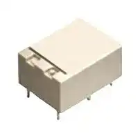


ADY10012
Power Relay, SPST-NO, 12 VDC, 10 A, DY Series, Through Hole
- Manufacturer: PANASONIC
- Product type: Power Relays
- SVHC: To Be Advised
- Coil Type: -
- Coil Voltage: 12VDC
- Product Range: DY Series
- Relay Mounting: Through Hole
- Coil Resistance: 720ohm
- Contact Current: 10A
- Relay Terminals: Solder
- Contact Material: Silver Nickel
- Contact Voltage VAC: 250V
- Contact Voltage VDC: 30V
- Contact Configuration: SPST-NO
| Delivery and price | |
|---|---|
| Units per pack | 50 |
| Price | 11.45 € |
| Current stock | 10+ |
| Lead time | 30 days |
## Power Relays ( Over 2 A ) DY RELAYS

Product Catalog

**==> picture [503 x 408] intentionally omitted <==**

2023.1

## **Power Relays (Over 2 A)**

## **DY[RELAYS]**

## **1 Form A 10 A, 1 Form A 1 Form B 8 A, Small polarized power relays**

~~e~~ ~~**FEATURES** e~~ **High capacity 1 Form A (10 A 250 V AC), 1 Form A 1 Form B (8 A 250 V AC) Compliance with the IEC standard EN61010-1 (Reinforced insulation with 6 mm distance between input and output) Variety of contact arrangements (1 Form A, 1 Form A 1 Form B) PC board sockets are available Latching types available**

Protective construction:Sealed type **High capacity 1 Form A (10 A 250 V AC), 1 Form A 1 Form B (8 A 250 V AC) Compliance with the IEC standard EN61010-1 (Reinforced insulation with 6 mm distance between input and output)** 20 15 **Variety of contact arrangements (1 Form A, 1 Form A** 10 **1 Form B)** ro) **PC board sockets are available Latching types available** ~~P~~ ~~**TYPICAL APPLICATIONS** e~~ **Control for machine tools and robots Output for temperature controller, PLC, timers and sensors Measuring equipment** (Unit:mm) **Security equipment**

## Pe **ORDERING INFORMATION (PART NO.)**

|||**ADY**|**ADY**||||||||||||||||
|---|---|---|---|---|---|---|---|---|---|---|---|---|---|---|---|---|---|---|
|Operating function<br>Contact arrangement<br>~~a~~|||||||Protective construction||Rated coil voltage(DC)||||||||||
|1:1 Form A<br>3:1 Form A 1 Form B|1 Form A<br>1 Form A 1 Form B|||1 Form A 1 Form B|0:Single side stable<br>2:2 coil latching||0:Plastic sealed||Part No.<br>Rated coil voltage(V)<br>03<br>3<br>06<br>6<br>09<br>9<br>12<br>12<br>24<br>24<br>05<br>5<br>~~———+H4~~||||||||||
|**TYPES**|||||||||||||||||||
|Contact arrangement|||Rated coil voltage||Rated coil voltage||Part No.<br>Single side stable||Part No.<br>2coil latching||||Standard packing<br>Inner carton<br>Outer carton||||||
||||||3V DC||ADY10003||ADY12003||||||||||
||||||5V DC||ADY10005||ADY12005||||||||||
|1Form A|||||6V DC<br>9V DC||ADY10006<br>ADY10009||ADY12006<br>ADY12009||||||||||
|||||12V DC|||ADY10012||ADY12012||||||||||
|||||24V DC<br>3V DC|||ADY10024<br>ADY30003||ADY12024<br>ADY32003|||||50pcs.||pcs.||500pcs.|
||||||5V DC||ADY30005||ADY32005||||||||||
|1Form A1Form B|||||6V DC<br>9V DC||ADY30006<br>ADY30009||ADY32006<br>ADY32009||||||||||
|||||12V DC|||ADY30012||ADY32012||||||||||
|||||24V DC|||ADY30024||ADY32024||||||||||


## **TYPES**

For the sockets, please refer to the “PC board sockets”.

Panasonic Industry Co., Ltd. Electromechanical Control Business Division industrial.panasonic.com/ac/e/

ASCTB182E   202301

ー 1 ー

Panasonic Industry Co., Ltd. 2021

~~eec~~ Power Relays (Over 2 A ~~reer~~ rere ) reer DY RELAYS c **e** ce

## **RATING**

## **Coil data**

## temperature, etc.

## Single side stable

|Rated coil<br>voltage<br>3V DC<br>5V DC||Operate voltage*<br>(at20°C)|Release voltage*<br>(at20°C)|Rated operating<br>current<br>10<br>20°C)<br>Coil resistance<br>10<br>20°C)<br>66.6mA<br>45<br>40mA<br>125<br>Rated operating power<br>(+<br>%, at<br>(+<br>%, at<br>~~ee~~<br>~~ee ee~~<br>~~oo~~|Rated operating<br>current<br>10<br>20°C)<br>Coil resistance<br>10<br>20°C)<br>66.6mA<br>45<br>40mA<br>125<br>Rated operating power<br>(+<br>%, at<br>(+<br>%, at<br>~~ee~~<br>~~ee ee~~<br>~~oo~~|voltage<br>(at20°C)<br>Max. allowable|
|---|---|---|---|---|---|---|
|6V DC<br>9V DC<br>12V DC<br>24V DC<br>*square, pulse drive||Max.70<br>rated coil voltage<br>(Initial)<br>9|Min.10<br>rated coil voltage<br>(Initial)<br>0|200mW<br>33.3mA<br>180<br>22.2mA<br>405<br>16.6mA<br>720<br>8.3mA<br>2,880<br> ~~oo~~<br>~~oo~~<br>~~ee ee ee~~||130<br>rated coil voltage|
|2 coil latching|||||||
|Rated coil<br>voltage<br>3V DC<br>5V DC||Set voltage*<br>(at20°C)|Reset voltage*<br>(at20°C)|Rated operating<br>current<br>10<br>20°C)<br>Coil resistance<br>10<br>20°C)<br>Set coil<br>Reset coil<br>Set coil<br>Reset coil<br>66.6mA<br>66.6mA<br>45<br>45<br>40mA<br>40mA<br>125<br>125<br>~~—~~<br>~~||~~|voltage<br>(at20°C)<br>Set coil<br>Reset coil<br>Rated operating power | Max. allowable||
|6V DC<br>9V DC<br>12V DC<br>24V DC<br>*square, pulse drive||Max.70<br>rated coil voltage<br>(Initial)<br>9|Max.70<br>rated coil voltage<br>(Initial)<br>0|200mW<br>200mW<br>33.3mA<br>33.3mA<br>180<br>180<br>22.2mA<br>22.2mA<br>405<br>405<br>16.6mA<br>16.6mA<br>720<br>720<br>8.3mA<br>8.3mA<br>2,880<br>2,880<br> ~~|~~<br>~~|~~<br>~~ee~~ee<br>ee<br>~~eee~~||130<br>rated coil voltage|


*square, pulse drive

## 2 coil latching

*square, pulse drive

|Item|Item|Specifications|Specifications|
|---|---|---|---|
|Contact data|Contact arrangement|1Form A|1Form A1Form B|
||Contact resistance (initial)|Max.30<br>6V DC1A)||
||Contact material|2||
||Contact rating (resistive)|10A250V AC,10A30V DC|8A250V AC,8A30V DC|
||(resistive)|2,500VA,300W|2,000VA,240W|
||Max. switching voltage|250V AC,125V DC (0.2A)||
|||10A|8A|
||(reference value) *1<br>Min. switching load|10mA5V DC||
|Insulation resistance (initial)||Min.1,000<br>500V DC, Measured portion is the same as the case of dielectric strength.)<br>MQ (at||
|Dielectric<br>strength<br>(initial)|Between open contacts<br>~~Betweencontactsets~~<br>~~f=~~|1,000Vrms for1min (detection current:10mA)<br>~~f=~~||
||~~Betweencontactsets~~<br>~~f=~~|~~f=~~|4,000Vrms for1min|
||~~Between contactsets~~<br>~~f=~~<br>Between contact and coil|4,000Vrms for1min (detection current:10mA)<br>~~f=~~||
|voltage (initial) *2<br>SoGSEM|Between contactand coil|10,000V||
|Time<br>characteristics<br>(initial)<br>~~PY~~<br>~~CC~~|Operate (Set) time<br>~~PY~~|Max.10ms (Max.10ms) at rated coil voltage (at20<br>°C,withoutbounce,without diode)||
||Release (Reset) time<br>~~PY~~<br>~~CC~~|Max.8ms (Max.10ms) at rated coil voltage (at20<br>°C,withoutbounce,without diode)<br>5)||
|Shock<br>resistance<br>~~PY~~<br>~~CC~~|Functional<br>~~PY~~<br>~~CC~~|98m/s2(half-sine shock pulse:11ms, detection time:10<br>°C,withoutbounce,without diode)<br>5)||
||Destructive<br>~~CC~~<br>~~C~—S~~|980m/s2(half-sine shock pulse:6ms)<br>5)<br>~~C~—S~~<br>V8)||
|Vibration<br>resistance<br>switchinglife~~Po~~|Functional<br>~~C~—S~~|10to55Hz (at double amplitude of1.5mm) (detection time:10<br>~~C~—S~~<br>V8)||
||Destructive<br>~~C~—S~~<br>~~Po~~|10to55Hz (at double amplitude of3mm)<br>~~C~—S~~<br>V8)<br>ope.(switchingfrequency:at||
|Expected<br>switchinglife~~Po~~<br>Po|Mechanical<br>~~Po~~<br>Po|Min.50x106<br>300times/min)<br>ope.(switchingfrequency:at<br>°CHumidity:<br>%RH(Avoidicingandcondensation)||
|Use condition<br>switching life ~~Po~~<br>Po|Conditions for usage,<br>transport and storage*3<br>~~Po~~<br>Po|Ambient temperature: -40to +70<br>5to85<br>ope.(switchingfrequency: at<br>°CHumidity:<br>%RH(Avoidicingandcondensation)||
|Po<br>Unit weight||Approx.6g<br>°C Humidity:<br>%RH(Avoid icingandcondensation)||


- *3. For ambient temperature, please read “GUIDELINES FOR RELAY USAGE”.

Panasonic Industry Co., Ltd. Electromechanical Control Business Division industrial.panasonic.com/ac/e/

ASCTB182E   202301

ー 2 ー © Panasonic Industry Co., Ltd. 2021

Power Relays (Over 2 A)  DY RELAYS

~~errr~~ e reerrececece ~~cece~~

## **Expected electrical life**

**==> picture [409 x 59] intentionally omitted <==**

**----- Start of picture text -----**<br>
Type Number of operations<br>1 Form A Po 10 A 250 V AC Min. 100 x 10 [3]  ope.<br>|rrt—“‘“‘CS™S*S*:”SCCOC‘*sdC 10 A 30 V DC Min. 100 x 10 [3]  ope.<br>1 Form A 1 Form B |rrr—“(‘“‘(C‘C:;*S*S*S”™”™”CC‘ésdC 8 A 250 V AC Min. 100 x 10 [3]  ope.<br>PY 8 A 30 V DC Min. 100 x 10 [3]  ope.<br>**----- End of picture text -----**<br>


## **REFERENCE DATA**

**==> picture [513 x 605] intentionally omitted <==**

**----- Start of picture text -----**<br>
1-1.Max. switching capacity (1 Form A) 1-2.Max. switching capacity 2-1. Coil temperature characteristics<br>(1 Form A 1 Form B) (1 Form A)<br>Tested sample:ADY10024 Tested sample:ADY30024 Tested sample:ADY10024, 6 pcs.<br>Ambient temperature : 20℃<br>50<br>LCi AC resistive loa d Ett tA 40<br>AC resistive load 10A<br>10 AC indu ctive load 10<br>5 Tg (cosφ= 0.4) 5 Ny (AC induccosφ=0 tive load.4) 30 PTT 0A<br>DC resistive load<br>DC resistive load<br>ee Gan eee EAE a og 20 Pf tfbeaLd<br>1 1<br>DC inductive load<br>Ett (L/R=7ms) ( DC inductive loadL/R = 7ms ) 10 |<br>ie Lu AN ery Td<br>0.1 LLU 10 TET AS UIII 100 250 TV TH 1,000 0.1 SMMPETTIT 10 30 UIIN 100 Sitti: 250 T T T 1,000 0 80 TTT 90 100 110  TI 120 130<br>Contact voltage(V) Contact voltage(V) Coil applied voltage(%V)<br>2-2. Coil temperature characteristics   3-1. Ambient temperature characteristics   3-2. Ambient temperature characteristics<br>(1 Form A 1 Form B) (1 Form A) (1 Form A 1 Form B)<br>Tested sample:ADY30024, 6 pcs. Tested sample:ADY10024, 6 pcs. Tested sample:ADY30024, 6 pcs.<br>Ambient temperature:20℃ Ambient temperature:-40℃ to +70℃ Ambient temperature:-40℃ to +70℃<br>50 15 15<br>40 PT} ptf TTT.Pr PAA 10 LOTT, TTT.PT qaae 10 LOTTI Operate v oltage<br>Operate v oltage<br>8A 5 5<br>30 PTT tf fd PPPpoe PeLEE P Oeere PeLEP yy,<br>0A 0 Release voltage 0 Release v oltage<br>-40 -20 0 20 40 60 80 -40 -20 0 20 40 60 80<br>20 PeeIT | FCO,eS -5 Cer Ambient temperature (℃) Hoeee -5 Ambient temperature (℃)<br>10 Cert— iT) = aaEE -10 eeoorae -10<br>0 Pe] ] td AEPPEEPFPP -15 LETTFP PEPE P ette) -15 EEEPE<br>80 90 100 110 120 130<br>Coil applied voltage(%V)<br>DIMENSIONS CAD Unit: mm<br>Po GD The CAD data of the products with a “CAD” mark can be downloaded from our Website. The CAD data of the products with a “CAD” mark can be downloaded from our Website. CAD data of the products with a “CAD” mark can be downloaded from our Website. data of the products with a “CAD” mark can be downloaded from our Website. of the products with a “CAD” mark can be downloaded from our Website. the products with a “CAD” mark can be downloaded from our Website. products with a “CAD” mark can be downloaded from our Website. with a “CAD” mark can be downloaded from our Website. a “CAD” mark can be downloaded from our Website. “CAD” mark can be downloaded from our Website. can be downloaded from our Website. downloaded from our Website. from our Website. Website.<br>| 1 Form A<br>e Single side stable<br>a» CAD External dimensions Recommended PC board pattern  Schematic<br>20 (BOTTOM VIEW) (BOTTOM VIEW)<br>2-φ0.9 10.16 7.62 2-φ1.1 (De-energize)<br>e y 1 3 4<br>–<br>PettyPettyyyyy tt +8<br>. la JP InEREERI<br>aeeeeen Note: Since the connection to the coil should   this is a polarized relay,<br>be done according to the above<br>Tolerance ±0.1 schematic.<br>0.4 | 0.8 ll 0.8 0.4<br>10.16 7.62 i 1.11 10.16<br>General tolerance ±0.3<br>)A )A (℃)<br>(Contact current (Contact current Temperature rise<br>%)<br>(%) (<br>(℃)<br>Rate of change Rate of change<br>Temperature rise<br>15<br>10.16<br>10 9.7<br>3.5<br>**----- End of picture text -----**<br>


**==> picture [377 x 16] intentionally omitted <==**

**----- Start of picture text -----**<br>
DIMENSIONS CAD<br>Po GD The CAD data of the products with a “CAD” mark can be downloaded from our Website. The CAD data of the products with a “CAD” mark can be downloaded from our Website. CAD data of the products with a “CAD” mark can be downloaded from our Website. data of the products with a “CAD” mark can be downloaded from our Website. of the products with a “CAD” mark can be downloaded from our Website. the products with a “CAD” mark can be downloaded from our Website. products with a “CAD” mark can be downloaded from our Website. with a “CAD” mark can be downloaded from our Website. a “CAD” mark can be downloaded from our Website. “CAD” mark can be downloaded from our Website. can be downloaded from our Website. downloaded from our Website. from our Website. Website.<br>**----- End of picture text -----**<br>


Panasonic Industry Co., Ltd. Electromechanical Control Business Division industrial.panasonic.com/ac/e/

ASCTB182E   202301

ー 3 ー

Panasonic Industry Co., Ltd. 2021

~~eec~~ Power Relays (Over 2 A ~~reer~~ rere ) reer DY RELAYS c **e** ce

## 2 coil latching

**==> picture [413 x 166] intentionally omitted <==**

**----- Start of picture text -----**<br>
External dimensions Recommended PC board pattern  Schematic<br>20 (BOTTOM VIEW) (BOTTOM VIEW)<br>3-φ0.9 2.54 7.62 7.62 2-φ1.1 (Reset)<br>fl a<br>1 3 4<br>–<br>z COPEeee Te<br>o rtiyitttTEEty PyTyTyyyyt +8 +7<br>the connection to the coil should<br>be done according to the above<br>Tolerance ±0.1 schematic.<br>ih foo] | iit Note: Since this is a polarized relay,<br>— φ0.5 Li ! l 0.8 0.4 |iri | oe<br>K l | |<br>0.4 0.8<br>2.54 oa 7.62 7.62 1.11 10.16<br>General tolerance ±0.3<br>15<br>10.16<br>10 9.7<br>3.5<br>**----- End of picture text -----**<br>


**==> picture [513 x 185] intentionally omitted <==**

**----- Start of picture text -----**<br>
| 1 Form A 1 Form B<br>e Single side stable<br>CAD External dimensions Recommended PC board pattern  Schematic<br>20 (BOTTOM VIEW) (BOTTOM VIEW)<br>2 2-φ0.9 10.16 7.62 4-φ1.1 (De-energize)<br>“ | —<br>ATT 1 3 4<br>P ty tt Ty –<br>oe STSir | tT Pt ye + ut<br>GET TT Ty 8 6 i 5<br>HitWet [TE] tt eteTt dn Note: Since this is a polarized relay,<br>Rae the connection to the coil should<br>be done according to the above<br>Tolerance ±0.1 schematic.<br>0.4 0.8 0.8 0.4<br>10.16 7.62 1.11 10.16<br>ese ot —_es<br>General tolerance ±0.3<br>15<br>10.16<br>10 9.7<br>3.5<br>**----- End of picture text -----**<br>


## 2 coil latching

**==> picture [414 x 164] intentionally omitted <==**

**----- Start of picture text -----**<br>
External dimensions Recommended PC board pattern  Schematic<br>20 (BOTTOM VIEW) (BOTTOM VIEW)<br>3-φ0.9 2.54 7.62 7.62 4-φ1.1 (Reset)<br>/ | 44<br>[TT 1 3 4<br>p SSCey Tt Ty / – Lt<br>0 nase eee + +<br>eT Ty 8 7 6 Le 5<br>nt ET yt<br>the connection to the coil should<br>be done according to the above<br>Tolerance ±0.1 schematic.<br>i h] 00) oO] oO Note: Since this is a polarized relay,<br>— φ0.5 i 0.8 0.4 Li oe<br>| 0.4 L T ! 0.8 H ll Le | |<br>2.54 im 7.62 7.62 1.11 10.16<br>General tolerance ±0.3<br>15<br>10.16<br>10 9.7<br>3.5<br>**----- End of picture text -----**<br>


Panasonic Industry Co., Ltd. Electromechanical Control Business Division industrial.panasonic.com/ac/e/

ASCTB182E   202301

ー 4 ー

Panasonic Industry Co., Ltd. 2021

~~eec~~ Power Relays (Over 2 A ~~reer~~ rere ) reer DY RELAYS c **e** ce

## **SAFETY STANDARDS** ~~Po~~

## **UL (Approved)**

1 Form A

File No. Contact rating 10 A 250 V AC E43028 1 / 3 HP 125, 250 V AC 10A 30V DC 1 Form A 1 Form B File No. Contact rating 8A 250V AC E43028 1 / 4 HP 125, 250 V AC 8 A 30 V DC ~~||~~ **CSA (Approved)** 1 Form A File No. Contact rating 10 A 250 V AC 1509824 1 3 HP 125, 250 V AC 10 A 30 V DC — ~~—~~ 1 Form A 1 Form B File No. Contact rating 8 A 250 V AC 1509824 1 4 HP 125, 250 V AC 8 A 30 V DC — ~~—~~

## **VDE (Approved)**

1 Form A

|File No.|File No.||||Contact rating|Contact rating|
|---|---|---|---|---|---|---|
|40056169||10A|A|A250|VAC (cos@ =|1.0)|
|||10A|A|A30V DC (0ms)|||


## 1 Form A 1 Form B

|File No.|File No.||||Contact rating|Contact rating|
|---|---|---|---|---|---|---|
|40056169||8A|A|A250|VAC (cosg =|1.0)|
|||8A|A|A30V DC (0ms)|||


## **GUIDELINES FOR USAGE**

**For cautions for use, please read “GUIDELINES FOR RELAY USAGE”. https://industrial.panasonic.com/ac/e/control/relay/cautions_use/index.jsp**

## **Cautions for usage of DY relays**

Set and reset pulse time

the purpose of reliable operation under ambient temperature

time and release time.

setting the coil applied set and reset pulse time to 50 ms or more at the rated coil voltage.

Panasonic Industry Co., Ltd. Electromechanical Control Business Division industrial.panasonic.com/ac/e/

ASCTB182E   202301

Panasonic Industry Co., Ltd. 2021

ー 5 ー

Power Relays (Over 2 A)  DY RELAYS ~~reer~~ e erence eee **e**

## **PC board sockets**

## **SELECTOR CHART**

||||Socket|Socket|1Form A|1Form A|1Form A|1Form A||||1Form A|Form A1Form B|Form A1Form B|
|---|---|---|---|---|---|---|---|---|---|---|---|---|---|---|
|||||Single side stable||||2coil latching|||Single side stable|Single side stable|2coil latching||
|||1Form A|Single side stable<br>2coil latching|●||||●<br>●|||||||
|||1Form A|Single side stable||||||||●|||●|
|||1Form B|2coil latching|||||||||||●|
|**TYPES**|||||||||||||||
|~~e~~@|@|Carton packing|||||||||||||
|||Contact arrangement||Single side stable<br>Part No.|Part No.|||2coil latching<br>Part No.||||Standard packing<br>Inner carton<br>Outer carton|||
|||1Form A||DK1a-PS<br>AW3810||||DK1a-PSL2|||AW3810||||
|||1Form A1Form B||DK2a-PS<br>AW3820||||DK2a-PSL2|||AW3820|50pcs.||500pcs.|
|**RATING**|||||||||||||||
||||Item|||||Specifications|||||||
|Contact arrangement||||1Form A||||||1Form A1Form B||Form B|||
|Dielectric strength (initial)||||4,000Vrms for1min (detection current:10mA)<br>Each between terminals:<br>(Except for the portion between coil terminals)|||||||||||
|Insulation resistance (initial)||||1,000<br>(at500V DC, Measured portion is the same as the case of dielectric strength.)<br>Each between terminals: Min.<br>MQ|||||||||||
|||||10A||||||8A|||||
|Conditions||||Ambient temperature: -40to +<br>5to85<br>Humidity:<br>%RH(Avoid|to +65°C<br>(Avoidicing|||andcondensation)|||||||


**DIMENSIONS CAD** Po GD The CAD data of the products with a “CAD” mark can be downloaded from our Website.

Unit: mm

**==> picture [463 x 174] intentionally omitted <==**

**----- Start of picture text -----**<br>
Single side stable<br>CAD<br>External dimensions Recommended PC board pattern<br>(BOTTOM VIEW)<br>[] [J —i) -—»<br>po 1 Form A 1 Form A 1 Form B<br>pF} Ba<br>Oy i i |_. 4ーφ1.2 6ーφ1.2<br>[ s 23±0.6 z LiteeeTT TTT iy yy [igreRees<br>. pit TT yyy Pit TT yy tty<br>rt yyy ye ee et L{ yyy yyy yy ty<br>big t  tpt to big tt gt<br>a 7.62 10.16 a 7.62 10.16 tte<br>Tolerance ±0.1 Tolerance ±0.1<br>7.62 10.16 General tolerance ±0.3<br>0.6<br>±<br>15 10.16<br>10.16 10.16<br>0.6 0.6<br>± 0.1 ±<br>17 ±<br>6 0.3 13.7<br>.4<br>3<br>**----- End of picture text -----**<br>


Panasonic Industry Co., Ltd. Electromechanical Control Business Division industrial.panasonic.com/ac/e/

ASCTB182E   202301

ー 6 ー

Panasonic Industry Co., Ltd. 2021

~~eec~~ Power Relays (Over 2 A ~~reer~~ rere ) reer DY RELAYS c **e** ce

**==> picture [463 x 183] intentionally omitted <==**

**----- Start of picture text -----**<br>
2 coil latching<br>CAD<br>External dimensions Recommended PC board pattern<br>(BOTTOM VIEW)<br>is Cl OO 1 Form A 1 Form A 1 Form B<br>6ーφ1.2 8ーφ1.2<br>«Sd 23±0.6 CTT Seaerenecen<br>pty Ty yy yr eee<br>. pit Ty yyy yy Pit TT yyy tt<br>ity yyy eye ee ty L{ yyy yy ey ty<br>as 7.62 an 7.62 2.54 Pp 7.62 7.62 2.54<br>Tolerance ±0.1 Tolerance ±0.1<br>H 7.62 t 7.62 2.54±0.1<br>General tolerance ±0.3<br>0.6<br>±<br>15 10.16<br>10.16 10.16<br>0.6 0.6<br>± 0.1 ±<br>17 ±<br>6 0.3 13.7<br>.4<br>3<br>**----- End of picture text -----**<br>


## **HANDLING**

## **Mounting method of relay**

## **Removing method of relay**

**==> picture [372 x 48] intentionally omitted <==**

**----- Start of picture text -----**<br>
2)  In case there is not enough<br>Both ends of relays are fixed space for finger to pick relay<br>so tightly that the socket up, use screw drivers in the<br>hooks on the top surface of  way as shown in the figure.<br>**----- End of picture text -----**<br>


Panasonic Industry Co., Ltd. Electromechanical Control Business Division industrial.panasonic.com/ac/e/

ー 7 ー © Panasonic Industry Co., Ltd. 2021 ASCTB182E   202301

**GUIDELINES FOR POWER, HIGH-CAPACITY DC CUT OFF AND SAFETY RELAYS USAGE**

## **For cautions for use, please read “GUIDELINES FOR RELAY USAGE”. https://industrial.panasonic.com/ac/e/control/relay/cautions_use/index.jsp**

## **Precautions for Coil Input**

## **Long term current carrying**

A circuit that will be carrying a current continuously for long periods without relay switching operation. (circuits for emergency lamps, alarm devices and error inspection that, for example, revert only during malfunction and output warnings with form B contacts) Continuous, long-term current to the coil will facilitate deterioration of coil insulation and characteristics due to heating of the coil itself. For circuits such as these, please use a magnetic-hold type latching relay. If you need to use a single stable relay, use a sealed type

failsafe circuit design that considers the possibility of contact failure or disconnection.

## **DC Coil operating power**

Steady state DC current should be applied to the coil. The wave form should be rectangular. If it includes ripple, the ripple factor should be less than 5%.

characteristics may vary. The rated coil voltage should be applied to

## **Maximum allowable voltage and temperature rise**

Proper usage requires that the rated coil voltage be impressed on the coil. Note, however, that if a voltage greater than or equal to the maximum continuous voltage is impressed on the coil, the coil may burn or its layers short due to the temperature rise. Furthermore, do not exceed the usable ambient temperature range listed in the catalog.

## **Operate voltage change due to coil temperature rise**

- In DC relays, after continuous passage of current in the coil, if the current is turned OFF, then immediately turned ON again, due to the temperature rise in the coil, the operate voltage will become somewhat higher. Also, it will be the same as using it in a higher temperature atmosphere. The resistance/temperature relationship for copper wire is about 0.4% for 1°C, and with this ratio the coil resistance increases. That is, in order to operate of the relay, it is necessary that the voltage be higher than the operate voltage and the operate voltage rises in accordance with the increase in the resistance value. However, for some polarized relays, this rate of change is considerably smaller.

## **Coil connection**

(+,-) at the internal connection diagram (Schematic). If any wrong

impressing voltages to the set coil and reset coil at the same time.

## **Ambient Environment**

## **Usage, Transport, and Storage Conditions**

During usage, storage, or transportation, avoid locations subjected to direct sunlight and maintain normal temperature, humidity and pressure conditions.

## **Dew condensation**

Condensation occurs when the ambient temperature drops suddenly from a high temperature and humidity, or the relay is suddenly transferred from a low ambient temperature to a high temperature

## **Temperature/Humidity/Pressure**

deterioration, wire disconnection and rust etc.

Panasonic Industry Co., Ltd. does not guarantee the failures caused by condensation.

The heat conduction by the equipment may accelerate the cooling of device itself, and the condensation may occur.

Please conduct product evaluations in the worst condition of the actual usage. (Special attention should be paid when high temperature heating parts are close to the device. Also please consider the condensation may occur inside of the device.)

## 1) Temperature:

## **Icing**

Condensation or other moisture may freeze on relays when the

## 2) Humidity: 5 to 85 % RH

**==> picture [140 x 139] intentionally omitted <==**

**----- Start of picture text -----**<br>
Humidity (% RH)<br>85<br>Yi ,<br>Allowa b le range<br>Avoid icing Avoid con-<br>when used at densation when<br>temperatures used at tem-<br>lower than 0°C peratures higher<br>than 0°C<br>5 ooo<br>-40 0 85<br>Ambient temperature (℃)<br>**----- End of picture text -----**<br>


of movable portion, the operation delay and the contact conduction failure etc. Panasonic Industry Co., Ltd. does not guarantee the failures caused by the icing.

The heat conduction by the equipment may accelerate the cooling of relay itself and the icing may occur. Please conduct product evaluations in the worst condition of the actual usage.

## **Low temperature and low humidity**

The plastic becomes brittle if the switch is exposed to a low temperature, low humidity environment for long periods of time.

## **High temperature and high humidity**

Storage for extended periods of time (including transportation periods) at high temperature or high humidity levels or in atmospheres with organic gases or sulfide gases may cause a

which the units are to be stored and transported.

Panasonic Industry Co., Ltd. Electromechanical Control Business Division industrial.panasonic.com/ac/e/

ー 8 ー © Panasonic Industry Co., Ltd. 2022 ASCTB412E   202204

## GUIDELINES FOR POWER, HIGH-CAPACITY DC CUT OFF AND SAFETY RELAYS USAGE

## **Package**

minimum.

## **Silicon**

## **NOx Generation**

When relay is used in an atmosphere high in humidity to switch a load which easily produces an arc, the NOx created by the arc and the water absorbed from outside the relay combine to produce nitric acid.

When a source of silicone substances (silicone rubber, silicone oil,

operation.

around the relay, the silicone gas (low molecular siloxane etc.) may be produced.

This silicone gas may penetrate into the inside of the relay. When

Avoid use at an ambient humidity of 85%RH or higher (at 20°C). If use at high humidity is unavoidable, please contact our sales representative.

adhere to the relay contacts which may cause the contact failure. Do not use any sources of silicone gas around the relay (Including plastic seal types).

## **Others**

## **Cleaning**

- Although the environmentally sealed type relay (plastic sealed type, etc.) can be cleaned, avoid immersing the relay into cold liquid (such as cleaning solvent) immediately after soldering. Doing so may deteriorate the sealing performance.

- Cleaning with the boiling method is recommended(The temperature of cleaning liquid should be 40°C or lower ). Avoid ultrasonic cleaning on relays. Use of ultrasonic cleaning may

ultrasonic energy.

Please refer to “the latest when designing your product.

•Requests to customers: https://industrial.panasonic.com/ac/e/salespolicies/

Panasonic Industry Co., Ltd. Electromechanical Control Business Division industrial.panasonic.com/ac/e/

ー 9 ー © Panasonic Industry Co., Ltd. 2022

ASCTB412E   202204

■ Global Sales Network Information: industrial.panasonic.com/ac/e/salesnetwork

Electromechanical Control Business Division 1006, Oaza Kadoma, Kadoma-shi, Osaka 571-8506, Japan industrial.panasonic.com/ac/e/

Specifications are subject to change without notice.

©Panasonic Industry Co., Ltd. 2023

2023.1

������������������
Updated at June 7, 2026
Panasonic Industry is a global leader in the design and manufacture of high-quality electronic components. Renowned for a commitment to continuous innovation, the company provides the essential building blocks that empower modern engineering. From industrial automation to consumer electronics, Panasonic's components are trusted worldwide for their outstanding reliability, efficiency, and long-term performance. The extensive portfolio is anchored by a massive selection of passive components, featuring an industry-leading range of aluminium electrolytic, film, and polymer capacitors. Alongside these advanced capacitance solutions, engineers rely on Panasonic's robust power inductors and a highly versatile array of electromechanical devices, including solid-state, power, and signal relays engineered to excel in demanding environments. Beyond core passives and switching solutions, the offering encompasses critical circuit protection devices such as TVS varistors and NTC thermistors, as well as sophisticated thermal management materials. Panasonic also delivers precision light and motion sensors, highly reliable batteries, and advanced Bluetooth and WLAN connectivity modules, providing a comprehensive ecosystem of components to support next-generation technological design.
About Novapart
Novapart is a B2B electronic component broker specialising in stock shortages and cost reduction. We source hard-to-find parts and identify compliant alternatives across a catalogue of 540,000+ components from 500+ manufacturers.
Learn more →Stock Shortage Specialist
When a component is unavailable, discontinued or has an unacceptable lead time, we tap into our network of vetted European and Asian distributors to source what you need — without compromising on quality or traceability.
Request a quote →Compliant Alternatives
We identify pin-to-pin, electrically equivalent substitutes that meet the same certifications (RoHS, AEC-Q100, REACH) as your original specification — validated against datasheets, not just part numbers. Often at a lower cost.
BOM Analysis service →